EP3478101B1 - Batteriebetriebene aerosolerzeugungs-vorrichtung mit temperaturabhängiger batterievorheizung - Google Patents
Batteriebetriebene aerosolerzeugungs-vorrichtung mit temperaturabhängiger batterievorheizung Download PDFInfo
- Publication number
- EP3478101B1 EP3478101B1 EP17731854.0A EP17731854A EP3478101B1 EP 3478101 B1 EP3478101 B1 EP 3478101B1 EP 17731854 A EP17731854 A EP 17731854A EP 3478101 B1 EP3478101 B1 EP 3478101B1
- Authority
- EP
- European Patent Office
- Prior art keywords
- aerosol
- eesd
- accessory
- generating
- temperature sensor
- Prior art date
- Legal status (The legal status is an assumption and is not a legal conclusion. Google has not performed a legal analysis and makes no representation as to the accuracy of the status listed.)
- Active
Links
Images


Classifications
-
- A—HUMAN NECESSITIES
- A24—TOBACCO; CIGARS; CIGARETTES; SIMULATED SMOKING DEVICES; SMOKERS' REQUISITES
- A24F—SMOKERS' REQUISITES; MATCH BOXES; SIMULATED SMOKING DEVICES
- A24F40/00—Electrically operated smoking devices; Component parts thereof; Manufacture thereof; Maintenance or testing thereof; Charging means specially adapted therefor
- A24F40/50—Control or monitoring
- A24F40/57—Temperature control
-
- A—HUMAN NECESSITIES
- A24—TOBACCO; CIGARS; CIGARETTES; SIMULATED SMOKING DEVICES; SMOKERS' REQUISITES
- A24F—SMOKERS' REQUISITES; MATCH BOXES; SIMULATED SMOKING DEVICES
- A24F40/00—Electrically operated smoking devices; Component parts thereof; Manufacture thereof; Maintenance or testing thereof; Charging means specially adapted therefor
- A24F40/50—Control or monitoring
- A24F40/51—Arrangement of sensors
-
- A—HUMAN NECESSITIES
- A24—TOBACCO; CIGARS; CIGARETTES; SIMULATED SMOKING DEVICES; SMOKERS' REQUISITES
- A24D—CIGARS; CIGARETTES; TOBACCO SMOKE FILTERS; MOUTHPIECES FOR CIGARS OR CIGARETTES; MANUFACTURE OF TOBACCO SMOKE FILTERS OR MOUTHPIECES
- A24D3/00—Tobacco smoke filters, e.g. filter-tips, filtering inserts; Filters specially adapted for simulated smoking devices; Mouthpieces for cigars or cigarettes
- A24D3/17—Filters specially adapted for simulated smoking devices
-
- A—HUMAN NECESSITIES
- A24—TOBACCO; CIGARS; CIGARETTES; SIMULATED SMOKING DEVICES; SMOKERS' REQUISITES
- A24F—SMOKERS' REQUISITES; MATCH BOXES; SIMULATED SMOKING DEVICES
- A24F40/00—Electrically operated smoking devices; Component parts thereof; Manufacture thereof; Maintenance or testing thereof; Charging means specially adapted therefor
- A24F40/20—Devices using solid inhalable precursors
-
- A—HUMAN NECESSITIES
- A24—TOBACCO; CIGARS; CIGARETTES; SIMULATED SMOKING DEVICES; SMOKERS' REQUISITES
- A24F—SMOKERS' REQUISITES; MATCH BOXES; SIMULATED SMOKING DEVICES
- A24F40/00—Electrically operated smoking devices; Component parts thereof; Manufacture thereof; Maintenance or testing thereof; Charging means specially adapted therefor
- A24F40/50—Control or monitoring
-
- A—HUMAN NECESSITIES
- A24—TOBACCO; CIGARS; CIGARETTES; SIMULATED SMOKING DEVICES; SMOKERS' REQUISITES
- A24F—SMOKERS' REQUISITES; MATCH BOXES; SIMULATED SMOKING DEVICES
- A24F40/00—Electrically operated smoking devices; Component parts thereof; Manufacture thereof; Maintenance or testing thereof; Charging means specially adapted therefor
- A24F40/90—Arrangements or methods specially adapted for charging batteries thereof
-
- A—HUMAN NECESSITIES
- A61—MEDICAL OR VETERINARY SCIENCE; HYGIENE
- A61M—DEVICES FOR INTRODUCING MEDIA INTO, OR ONTO, THE BODY; DEVICES FOR TRANSDUCING BODY MEDIA OR FOR TAKING MEDIA FROM THE BODY; DEVICES FOR PRODUCING OR ENDING SLEEP OR STUPOR
- A61M15/00—Inhalators
- A61M15/06—Inhaling appliances shaped like cigars, cigarettes or pipes
-
- H—ELECTRICITY
- H01—ELECTRIC ELEMENTS
- H01M—PROCESSES OR MEANS, e.g. BATTERIES, FOR THE DIRECT CONVERSION OF CHEMICAL ENERGY INTO ELECTRICAL ENERGY
- H01M10/00—Secondary cells; Manufacture thereof
- H01M10/42—Methods or arrangements for servicing or maintenance of secondary cells or secondary half-cells
- H01M10/48—Accumulators combined with arrangements for measuring, testing or indicating the condition of cells, e.g. the level or density of the electrolyte
- H01M10/486—Accumulators combined with arrangements for measuring, testing or indicating the condition of cells, e.g. the level or density of the electrolyte for measuring temperature
-
- H—ELECTRICITY
- H01—ELECTRIC ELEMENTS
- H01M—PROCESSES OR MEANS, e.g. BATTERIES, FOR THE DIRECT CONVERSION OF CHEMICAL ENERGY INTO ELECTRICAL ENERGY
- H01M10/00—Secondary cells; Manufacture thereof
- H01M10/60—Heating or cooling; Temperature control
- H01M10/61—Types of temperature control
- H01M10/615—Heating or keeping warm
-
- H—ELECTRICITY
- H01—ELECTRIC ELEMENTS
- H01M—PROCESSES OR MEANS, e.g. BATTERIES, FOR THE DIRECT CONVERSION OF CHEMICAL ENERGY INTO ELECTRICAL ENERGY
- H01M10/00—Secondary cells; Manufacture thereof
- H01M10/60—Heating or cooling; Temperature control
- H01M10/62—Heating or cooling; Temperature control specially adapted for specific applications
- H01M10/623—Portable devices, e.g. mobile telephones, cameras or pacemakers
-
- H—ELECTRICITY
- H01—ELECTRIC ELEMENTS
- H01M—PROCESSES OR MEANS, e.g. BATTERIES, FOR THE DIRECT CONVERSION OF CHEMICAL ENERGY INTO ELECTRICAL ENERGY
- H01M10/00—Secondary cells; Manufacture thereof
- H01M10/60—Heating or cooling; Temperature control
- H01M10/63—Control systems
- H01M10/633—Control systems characterised by algorithms, flow charts, software details or the like
-
- H—ELECTRICITY
- H01—ELECTRIC ELEMENTS
- H01M—PROCESSES OR MEANS, e.g. BATTERIES, FOR THE DIRECT CONVERSION OF CHEMICAL ENERGY INTO ELECTRICAL ENERGY
- H01M10/00—Secondary cells; Manufacture thereof
- H01M10/60—Heating or cooling; Temperature control
- H01M10/65—Means for temperature control structurally associated with the cells
- H01M10/657—Means for temperature control structurally associated with the cells by electric or electromagnetic means
- H01M10/6571—Resistive heaters
-
- H—ELECTRICITY
- H02—GENERATION; CONVERSION OR DISTRIBUTION OF ELECTRIC POWER
- H02J—CIRCUIT ARRANGEMENTS OR SYSTEMS FOR SUPPLYING OR DISTRIBUTING ELECTRIC POWER; SYSTEMS FOR STORING ELECTRIC ENERGY
- H02J7/00—Circuit arrangements for charging or depolarising batteries or for supplying loads from batteries
- H02J7/0042—Circuit arrangements for charging or depolarising batteries or for supplying loads from batteries characterised by the mechanical construction
-
- H—ELECTRICITY
- H05—ELECTRIC TECHNIQUES NOT OTHERWISE PROVIDED FOR
- H05B—ELECTRIC HEATING; ELECTRIC LIGHT SOURCES NOT OTHERWISE PROVIDED FOR; CIRCUIT ARRANGEMENTS FOR ELECTRIC LIGHT SOURCES, IN GENERAL
- H05B1/00—Details of electric heating devices
- H05B1/02—Automatic switching arrangements specially adapted to apparatus ; Control of heating devices
- H05B1/0227—Applications
- H05B1/0297—Heating of fluids for non specified applications
-
- A—HUMAN NECESSITIES
- A24—TOBACCO; CIGARS; CIGARETTES; SIMULATED SMOKING DEVICES; SMOKERS' REQUISITES
- A24F—SMOKERS' REQUISITES; MATCH BOXES; SIMULATED SMOKING DEVICES
- A24F40/00—Electrically operated smoking devices; Component parts thereof; Manufacture thereof; Maintenance or testing thereof; Charging means specially adapted therefor
- A24F40/40—Constructional details, e.g. connection of cartridges and battery parts
- A24F40/46—Shape or structure of electric heating means
- A24F40/465—Shape or structure of electric heating means specially adapted for induction heating
-
- A—HUMAN NECESSITIES
- A24—TOBACCO; CIGARS; CIGARETTES; SIMULATED SMOKING DEVICES; SMOKERS' REQUISITES
- A24F—SMOKERS' REQUISITES; MATCH BOXES; SIMULATED SMOKING DEVICES
- A24F40/00—Electrically operated smoking devices; Component parts thereof; Manufacture thereof; Maintenance or testing thereof; Charging means specially adapted therefor
- A24F40/90—Arrangements or methods specially adapted for charging batteries thereof
- A24F40/95—Arrangements or methods specially adapted for charging batteries thereof structurally associated with cases
-
- A—HUMAN NECESSITIES
- A61—MEDICAL OR VETERINARY SCIENCE; HYGIENE
- A61M—DEVICES FOR INTRODUCING MEDIA INTO, OR ONTO, THE BODY; DEVICES FOR TRANSDUCING BODY MEDIA OR FOR TAKING MEDIA FROM THE BODY; DEVICES FOR PRODUCING OR ENDING SLEEP OR STUPOR
- A61M2205/00—General characteristics of the apparatus
- A61M2205/82—Internal energy supply devices
- A61M2205/8206—Internal energy supply devices battery-operated
-
- A—HUMAN NECESSITIES
- A61—MEDICAL OR VETERINARY SCIENCE; HYGIENE
- A61M—DEVICES FOR INTRODUCING MEDIA INTO, OR ONTO, THE BODY; DEVICES FOR TRANSDUCING BODY MEDIA OR FOR TAKING MEDIA FROM THE BODY; DEVICES FOR PRODUCING OR ENDING SLEEP OR STUPOR
- A61M2205/00—General characteristics of the apparatus
- A61M2205/82—Internal energy supply devices
- A61M2205/8237—Charging means
-
- H—ELECTRICITY
- H01—ELECTRIC ELEMENTS
- H01M—PROCESSES OR MEANS, e.g. BATTERIES, FOR THE DIRECT CONVERSION OF CHEMICAL ENERGY INTO ELECTRICAL ENERGY
- H01M2220/00—Batteries for particular applications
- H01M2220/30—Batteries in portable systems, e.g. mobile phone, laptop
-
- H—ELECTRICITY
- H01—ELECTRIC ELEMENTS
- H01M—PROCESSES OR MEANS, e.g. BATTERIES, FOR THE DIRECT CONVERSION OF CHEMICAL ENERGY INTO ELECTRICAL ENERGY
- H01M8/00—Fuel cells; Manufacture thereof
- H01M8/02—Details
- H01M8/0202—Collectors; Separators, e.g. bipolar separators; Interconnectors
- H01M8/0267—Collectors; Separators, e.g. bipolar separators; Interconnectors having heating or cooling means, e.g. heaters or coolant flow channels
-
- H—ELECTRICITY
- H01—ELECTRIC ELEMENTS
- H01M—PROCESSES OR MEANS, e.g. BATTERIES, FOR THE DIRECT CONVERSION OF CHEMICAL ENERGY INTO ELECTRICAL ENERGY
- H01M8/00—Fuel cells; Manufacture thereof
- H01M8/04—Auxiliary arrangements, e.g. for control of pressure or for circulation of fluids
- H01M8/04007—Auxiliary arrangements, e.g. for control of pressure or for circulation of fluids related to heat exchange
- H01M8/04037—Electrical heating
-
- H—ELECTRICITY
- H01—ELECTRIC ELEMENTS
- H01M—PROCESSES OR MEANS, e.g. BATTERIES, FOR THE DIRECT CONVERSION OF CHEMICAL ENERGY INTO ELECTRICAL ENERGY
- H01M8/00—Fuel cells; Manufacture thereof
- H01M8/04—Auxiliary arrangements, e.g. for control of pressure or for circulation of fluids
- H01M8/04007—Auxiliary arrangements, e.g. for control of pressure or for circulation of fluids related to heat exchange
- H01M8/04067—Heat exchange or temperature measuring elements, thermal insulation, e.g. heat pipes, heat pumps, fins
-
- H—ELECTRICITY
- H01—ELECTRIC ELEMENTS
- H01M—PROCESSES OR MEANS, e.g. BATTERIES, FOR THE DIRECT CONVERSION OF CHEMICAL ENERGY INTO ELECTRICAL ENERGY
- H01M8/00—Fuel cells; Manufacture thereof
- H01M8/04—Auxiliary arrangements, e.g. for control of pressure or for circulation of fluids
- H01M8/04223—Auxiliary arrangements, e.g. for control of pressure or for circulation of fluids during start-up or shut-down; Depolarisation or activation, e.g. purging; Means for short-circuiting defective fuel cells
- H01M8/04253—Means for solving freezing problems
-
- Y—GENERAL TAGGING OF NEW TECHNOLOGICAL DEVELOPMENTS; GENERAL TAGGING OF CROSS-SECTIONAL TECHNOLOGIES SPANNING OVER SEVERAL SECTIONS OF THE IPC; TECHNICAL SUBJECTS COVERED BY FORMER USPC CROSS-REFERENCE ART COLLECTIONS [XRACs] AND DIGESTS
- Y02—TECHNOLOGIES OR APPLICATIONS FOR MITIGATION OR ADAPTATION AGAINST CLIMATE CHANGE
- Y02E—REDUCTION OF GREENHOUSE GAS [GHG] EMISSIONS, RELATED TO ENERGY GENERATION, TRANSMISSION OR DISTRIBUTION
- Y02E60/00—Enabling technologies; Technologies with a potential or indirect contribution to GHG emissions mitigation
- Y02E60/10—Energy storage using batteries
Definitions
- the invention relates to battery powered aerosol generating systems and in particular handheld battery powered aerosol-generating systems that may be required to operate in a variety of different environments.
- Batteries for handheld aerosol-generating devices such as electrically heated smoking devices or e-cigarettes, are required to be small but at the same time must be able to deliver significant amounts of power over a period of just a few minutes, typically around 7 minutes for a single smoking session. It is also desirable that the batteries are rechargeable and that they can be recharged sufficiently to allow for another complete smoking experience in a matter of a few minutes and preferably less than 6 minutes.
- An example of a battery warm up system and method for warming up a battery is described in US 2015/0008887 A1 .
- An example of a pack for holding and recharging an e-cigarette is described in GB 2528711 A .
- the pack comprises a rechargeable pack battery, a first connector which is electrically connectable to an external power source, a first recharging mechanism for recharging the pack battery using the external power source comprising a first protection circuit, a second connector which is electrically connectable to an e-cigarette contained within the pack, and a second recharging mechanism for recharging the e-cigarette when it is electrically connected to second connector comprising a second protection circuit.
- the batteries for handheld aerosol-generating devices are small in order to keep the overall size of the device small, they typically need to be recharged frequently.
- the battery may have a capacity sufficient for only a single smoking session and so need recharging after each smoking session.
- portable chargers are provided with some devices.
- the portable chargers are themselves battery powered.
- the battery used in a portable charger also needs to have a relatively small size and high capacity.
- Lithium ion batteries can meet the requirements for both aerosol-generating devices and for portable chargers. But the performance of lithium ion batteries is significantly affected by temperature. Different batteries perform differently, but in general, at temperatures below 10 degrees Celsius, the performance of batteries, such as lithium ion batteries, as well as lithium capacitors, is significantly reduced. In particular, the available discharge capacity falls sharply below this temperature. This is a significant problem because aerosol-generating devices are routinely required to operate in cold climates or cold environments. Furthermore, aerosol-generating devices may be required to operate consistently at one moment in a cold environment, such as outdoors at a ski resort, and the next moment in a warm indoor environment. There may be a difference of as much as 40 degrees Celsius in the ambient temperature between one use and the next. In fact, from a manufacturing standpoint, aerosol-generating devices and portable chargers need to operate consistently over a range of as much as 60 degrees Celsius.
- the invention is defined in the appended independent claims, wherein an aerosol-generating system is defined in the independent claim 1 and a method of controlling operation of an aerosol-generating device is defined in the independent claim 18.
- Advantageous features of the invention are defined in the appended dependent claims.
- an aerosol-generating system comprising:
- the system may comprise a handheld aerosol-generating device and the aerosol-generating device may comprise the aerosol-generating element, the first EESD and the EESD temperature control system.
- the first EESD may be a battery or it may be a supercapacitor or a lithium capacitor (LIC).
- the first EESD may comprise a lithium ion battery.
- the first EESD comprises a lithium iron phosphate battery, but other battery types may be used.
- the first EESD is advantageously sized to fit in a handheld device and advantageously has a volume of no more than 100cm 3 .
- the first EESD is cylindrical.
- the first EESD may have a length between 5mm and 100mm.
- the first EESD has a length of 37mm and a diameter of 10 mm.
- the electrical heater is also advantageously of low volume.
- the electrical heater is configured to heat the first EESD efficiently so as to minimise power requirements for the electrical heater.
- the electrical heater may be positioned in direct contact with the first EESD and may heat the first EESD by conduction.
- the electrical heater may comprise a heating foil or a heating coil that is wrapped around the first EESD.
- the electrical heater may comprise an electrically resistive heater that generates heat by Joule heating when a current passes through it.
- the electrical heater may comprise a flexible substrate that is stable at high temperature.
- the electrical heater may comprise a polyimide substrate.
- the electrical heater may comprise one or more resistive heating tracks on the substrate.
- the resistive heating tracks may be formed from copper.
- the heater may have a thickness of between 0.05mm and 0.3mm and may have a length and width to completely cover the first EESD.
- the EESD temperature control system may be connected to, or integral with, a power controller configured to control a supply of electrical power from the first EESD to the aerosol-generating element.
- the power controller may be configured to prevent the supply of power from the first EESD to the aerosol-generating element dependent on an output from the at least one temperature sensor. In this way, the device may be prevented from operating unless the EESD is at a temperature at which it is able to provide satisfactory performance.
- the EESD temperature control system may comprise a microcontroller.
- the microcontroller may be a low temperature microcontroller. Microcontrollers are available with different ranges of operating temperature.
- the microcontroller is preferably an industrial grade or military grade microcontroller configured to operate at temperatures below 0 degrees Celsius.
- the microcontroller may be a programmable microprocessor.
- the power controller may comprise a microcontroller which may be a programmable microprocessor.
- the EESD temperature control system and the power controller may be implemented using a single microcontroller.
- the EESD temperature control system may be configured to monitor an electrical resistance of the electrical heater and may control power supplied to the electrical heater based on the electrical resistance.
- the EESD temperature control system may include a PID regulator for controlling the power supplied to the electrical heater.
- the controller may be configured to supply power to the heater as pulses of electrical power.
- the controller may be configured to alter the supply of power to the electrical heater by altering the duty cycle of the pulses of power.
- the first EESD may have electrical terminals and the EESD temperature control system may be connected to the EESD terminals so that the electrical heater can be powered by the first EESD. Even at low temperatures, the first EESD may be able to deliver enough power to operate the electrical heater. Alternatively, or in addition, the electrical heater may be powered by an auxiliary EESD within the device or a EESD that is external to the device.
- the aerosol-generating device may be a handheld smoking system.
- the aerosol-generating device may be configured to generate an aerosol from an aerosol-forming substrate.
- the aerosol-forming substrate may be received in the device.
- An aerosol-forming substrate is a substrate capable of releasing volatile compounds that can form an aerosol.
- the volatile compounds may be released by heating or combusting the aerosol-forming substrate.
- volatile compounds may be released by a chemical reaction or by a mechanical stimulus, such as vibration.
- the aerosol-forming substrate may be adsorbed, coated, impregnated or otherwise loaded onto a carrier or support.
- the aerosol-generating device may further comprise thermal insulation surrounding the first EESD.
- suitable thermal insulation include fibre based fabrics, such as glass wool and ceramic paper, ceramic powder based materials, such as perlite, vermiculite, alumina and silica based ceramics, polymers such as rubber, expanded or extruded polystyrene, polyurethane foam, polyisocyanurate foam, phenolic foam and polyimide foam, and aerogels.
- the thickness of the thermal insulation depends on the material and whether it is applied as a coating on the first EESD or as a separate layer. Generally the thicker the thermal insulation the better the thermal isolation. Preferably the thermal insulation is at least 1 mm thick.
- the thermal insulation may comprise an infra-red reflective layer.
- the infra-red reflective layer may be an aluminium foil or an aluminised polymer thin film.
- the film may have a thickness of about 0.02 mm.
- the infra-red reflective layer may be provided as a coating on the thermal insulation or EESD.
- the coating may comprise metal, such as aluminium, silver and gold, metal oxides, such as aluminium oxide, titanium dioxide, zinc oxide and cerium dioxide, or metal oxide mixed with dopants, such as fluorine, boron, aluminium, gallium, thallium, copper and iron.
- the thermal insulation may comprise a phase change material configured to release latent heat to the first EESD when the temperature of the phase change material drops below a threshold.
- the electrical heater may be activated if the output from the at least one temperature sensor indicates that the first EESD has a temperature of less than 10 degrees Celsius.
- any threshold temperature may be chosen depending on the characteristics of the first EESD and the power requirements of the aerosol-generating device.
- the threshold temperature may be varied dependent on one or more other measured parameters.
- the at least one temperature sensor may comprise a first temperature sensor positioned between the first EESD and the thermal insulation and a second temperature sensor positioned outside of the thermal insulation.
- the thermal insulation may be positioned between the first temperature sensor and the second temperature sensor.
- the electrical heater may activated dependent on an output from the first temperature sensor and an output from the second temperature sensor.
- the electrical heater may be activated when both the output from the first temperature sensor is below a first threshold and the output from the second temperature sensor is below a second threshold.
- the first threshold may be equal to the second threshold or may be different to the second threshold.
- the electrical heater may be activated when the output from the first temperature sensor is below a first threshold but may be deactivated dependent on a change in output from the second temperature sensor.
- the electrical heater may be activated when the output from the first temperature sensor is below a first threshold but the the value of the first threshold may be determined based on the output of the second temperature sensor.
- the electrical heater may always be activated when the output from the first temperature sensor indicates a temperature of less than 10 degrees Celsius, but the output of the second temperature sensor may determine that the electrical heater should be activated when the output from the first temperature sensor indicates a temperature of less than a threshold higher than 10 degrees Celsius. If the ambient temperature is higher than 10 degrees Celsius, the EESD may be heated until the output of the first temperature sensor is 10 degrees Celsius. If the ambient temperature is lower than 10 degrees Celsius, say -5 degrees Celsius, the EESD may be heated until the output of the first temperature sensor indicates a higher temperature, say 25 Degrees Celsius, to ensure that the first EESD remains fully functional despite continuing heat loss to the environment. Alternatively, the amount of power supplied to the electrical heater, and hence heating rate, may be dependent on the output from the second temperature sensor.
- An advantage of having a temperature sensor outside the thermal insulation in addition to a temperature sensor inside the thermal insulation is that the EESD temperature control system can react more quickly to changes in ambient temperature based on the output of the second temperature sensor and so reduce the risk of overheating the first EESD.
- the at least one temperature sensor may comprise one or more of: a resistance temperature detector (RTD), a thermistor, a silicon based integrated circuit (IC) temperature sensor and a thermocouple.
- RTD resistance temperature detector
- IC silicon based integrated circuit
- the aerosol-generating element may be an electric heater configured to heat an aerosol-forming substrate to produce an aerosol.
- the aerosol-generating element may comprise one or more heating elements.
- the one or more heating elements may comprise one or more resistive heating elements.
- the one or more heating elements may comprise one or more inductive heating elements.
- the one or more heating elements may comprise one or more resistive heating elements and one or more inductive heating elements.
- the one or more electric heating elements may have a temperature range in normal operation of between about 250 degrees Celsius and about 450 degrees Celsius.
- the one or more electric heating elements may comprise an electrically resistive material.
- Suitable electrically resistive materials include but are not limited to: semiconductors such as doped ceramics, electrically "conductive" ceramics (such as, for example, molybdenum disilicide), carbon, graphite, metals, metal alloys and composite materials made of a ceramic material and a metallic material. Such composite materials may comprise doped or undoped ceramics.
- the one or more electric heating elements may comprise an infra-red heating element, a photonic source, or an inductive heating element.
- the one or more electric heating elements may take any suitable form.
- the one or more electric heating elements may take the form of a heating blade.
- the one or more electric heating elements may take the form of a casing or substrate having different electroconductive portions, or an electrically resistive metallic tube.
- One or more heating needles or rods that run through the centre of the aerosol-forming substrate may be used.
- the one or more electric heating elements may be a disk (end) heating element or a combination of a disk heating element with heating needles or rods.
- the one or more electric heating elements may comprise a flexible sheet of material arranged to surround or partially surround the aerosol-forming substrate. Other possibilities include a heating wire or filament, for example a Ni-Cr, platinum, tungsten or alloy wire, or a heating plate.
- the one or more heating elements may be deposited in or on a rigid carrier material.
- the one or more electric heating elements may comprise a heat sink, or heat reservoir comprising a material capable of absorbing and storing heat and subsequently releasing the heat over time.
- the heat sink may be formed of any suitable material, such as a suitable metal or ceramic material.
- the material has a high heat capacity (sensible heat storage material), or is a material capable of absorbing and subsequently releasing heat via a reversible process, such as a high temperature phase change.
- Suitable heat storage materials include silica gel, alumina, carbon, glass mat, glass fibre, minerals, a metal or alloy such as aluminium, silver or lead, and a cellulose material such as paper.
- Other materials which release heat via a reversible phase change include paraffin, sodium acetate, naphthalene, wax, polyethylene oxide, a metal, metal salt, a mixture of eutectic salts or an alloy.
- the one or more heating elements may comprise an inductive heating element, such that, where the device forms part of an aerosol-generating system consisting of the aerosol generating device and a removable aerosol-generating article, no electrical contacts are formed between the article and the device.
- the device may comprise an inductor coil and a power supply configured to provide high frequency oscillating current to the inductor coil.
- the article may comprise a susceptor element positioned to heat the aerosol-forming substrate.
- a high frequency oscillating current means an oscillating current having a frequency of between 500 kHz and 10 MHz.
- the aerosol-generating device is portable.
- the aerosol-generating device may have a size comparable to a conventional cigar or cigarette.
- the aerosol-generating device may have a total length between approximately 30 mm and approximately 150 mm.
- the aerosol-generating device may have an external diameter between approximately 5 mm and approximately 30 mm.
- the aerosol-generating device may comprise a housing.
- the housing may be elongate.
- the housing may comprise any suitable material or combination of materials. Examples of suitable materials include metals, alloys, plastics or composite materials containing one or more of those materials, or thermoplastics that are suitable for food or pharmaceutical applications, for example polypropylene, polyetheretherketone (PEEK) and polyethylene. Preferably, the material is light and non-brittle.
- the housing may comprise a mouthpiece.
- the mouthpiece may comprise at least one air inlet and at least one air outlet.
- the mouthpiece may comprise more than one air inlet.
- One or more of the air inlets may reduce the temperature of the aerosol before it is delivered to a user and may reduce the concentration of the aerosol before it is delivered to a user.
- the term "mouthpiece" refers to a portion of an aerosol-generating device that is placed into a user's mouth in order to directly inhale an aerosol generated by the aerosol-generating device from an aerosol-generating article received in the cavity of the housing.
- the aerosol-generating device may include a user interface to activate the system, for example a button to initiate heating of the device or display to indicate a state of the device or the aerosol-forming substrate.
- the device may comprise one or more indicators. At least one indicator may be configured to indicate when an output of the at least one temperature sensor exceeds an operating threshold or is less than an operating threshold.
- the one or more indicators may be visual indicator and may include light emitting diodes (LEDs).
- the aerosol-forming substrate may be provided in an aerosol-generating article.
- An aerosol-generating article is an article comprising an aerosol-forming substrate that is capable of releasing volatile compounds that can form an aerosol.
- the aerosol-generating article may be a non-combustible aerosol-generating article or may be a combustible aerosol-generating article.
- the aerosol-generating article may generate an aerosol that is directly inhalable by a user.
- the aerosol-generating article may be a smoking article that generates an aerosol that is directly inhalable into a user's lungs through the user's mouth.
- the aerosol-generating article may resemble a conventional smoking article, such as a cigarette.
- the aerosol-generating article may be substantially cylindrical in shape.
- the aerosol-generating article may be substantially elongate.
- the aerosol-generating article may have a length and a circumference substantially perpendicular to the length.
- the aerosol-forming substrate may be substantially cylindrical in shape.
- the aerosol-forming substrate may be substantially elongate.
- the aerosol-forming substrate may also have a length and a circumference substantially perpendicular to the length.
- the aerosol-generating article may have a total length between approximately 30 mm and approximately 100 mm. In one embodiment, the aerosol-generating article has a total length of approximately 45 mm.
- the aerosol-generating article may have an external diameter between approximately 5 mm and approximately 12 mm. In one embodiment, the aerosol-generating article may have an external diameter of approximately 7.2 mm.
- the aerosol-forming substrate may have a length of between about 7 mm and about 15 mm. In one embodiment, the aerosol-forming substrate may have a length of approximately 10 mm. Alternatively, the aerosol-forming substrate may have a length of approximately 12 mm.
- the aerosol-generating substrate preferably has an external diameter that is approximately equal to the external diameter of the aerosol-generating article.
- the external diameter of the aerosol-forming substrate may be between approximately 5 mm and approximately 12 mm. In one embodiment, the aerosol-forming substrate may have an external diameter of approximately 7.2 mm.
- the aerosol-generating article may comprise a filter plug.
- the filter plug may be located at a downstream end of the aerosol-generating article.
- the filter plug may be a cellulose acetate filter plug.
- the filter plug is approximately 7 mm in length in one embodiment, but may have a length of between approximately 5 mm to approximately 10 mm.
- the aerosol-generating article may comprise an outer paper wrapper. Further, the aerosol-generating article may comprise a separation between the aerosol-forming substrate and the filter plug. The separation may be approximately 18 mm, but may be in the range of approximately 5 mm to approximately 25 mm.
- the aerosol-forming substrate may be a solid aerosol-forming substrate.
- the aerosol-forming substrate may comprise both solid and liquid components.
- the aerosol-forming substrate may comprise a tobacco-containing material containing volatile tobacco flavour compounds which are released from the substrate upon heating.
- the aerosol-forming substrate may comprise a non-tobacco material.
- the aerosol-forming substrate may further comprise an aerosol former that facilitates the formation of a dense and stable aerosol. Examples of suitable aerosol formers are glycerine and propylene glycol.
- the aerosol-generating system may comprise:
- the EESD temperature control system may be at least partially contained in the accessory.
- an EESD temperature sensor may be positioned in the accessory or some or all of the electrical heater may be positioned in the accessory
- the accessory may comprise an alternating current source and an induction coil configured to inductively heat the first EESD.
- the aerosol-generating device may comprise a susceptor.
- the susceptor may be integral with or part of the first EESD or may be positioned around or proximate to the first EESD.
- the induction coil and the susceptor may together form the electrical heater.
- the accessory may be a portable charger and the accessory EESD may be a charging EESD.
- the system may be configured to allow charging of a first EESD in the aerosol-generating device from the charging EESD.
- the accessory may comprise an accessory EESD temperature control system comprising at least one accessory temperature sensor positioned to sense a temperature of the accessory EESD, and a second electrical heater configured to heat the accessory EESD, wherein the accessory EESD temperature control system operates the second electrical heater dependent on an output from the at least one accessory temperature sensor.
- an accessory EESD temperature control system comprising at least one accessory temperature sensor positioned to sense a temperature of the accessory EESD, and a second electrical heater configured to heat the accessory EESD, wherein the accessory EESD temperature control system operates the second electrical heater dependent on an output from the at least one accessory temperature sensor.
- the accessory may comprise a heater configured to heat a first EESD in the aerosol-generating device based on a signal from a temperature sensor in the aerosol-generating device.
- the accessory EESD temperature control system may be connected to, or integral with, a charging power controller configured to control a supply of electrical power from the accessory EESD to the aerosol-generating device.
- the charging power controller may be configured to prevent the supply of power from the accessory EESD to the aerosol-generating device dependent on an output from the at least one charger temperature sensor.
- the accessory EESD may have electrical terminals and the accessory EESD temperature control system may be connected to the accessory EESD terminals so that the second electrical heater can be powered by the accessory EESD.
- the accessory EESD may be a lithium ion battery.
- the accessory EESD is a lithium cobalt oxide battery.
- the accessory EESD preferably has a capacity greater than the first EESD.
- the accessory EESD has a capacity at least five times greater than the capacity of the first EESD. This means that the accessory EESD can be used to provide several recharges of the first EESD.
- the larger capacity of the accessory EESD is advantageous for powering the electrical heater for the first EESD.
- the aerosol-generating system may further comprise second thermal insulation surrounding the accessory EESD.
- the second thermal insulation may comprise an infra-red reflective layer.
- the at least one accessory temperature sensor may comprise a first accessory temperature sensor positioned between the accessory EESD and the second thermal insulation and a second accessory temperature sensor positioned outside of the second thermal insulation.
- the second electrical heater may be activated dependent on an output from the first accessory temperature sensor and an output from the second accessory temperature sensor.
- the accessory electrical heater may be activated when both the output from the first accessory temperature sensor is below a first threshold and the output from the second accessory temperature sensor is below a second threshold.
- the first threshold may be equal to the second threshold or may be different to the second threshold.
- the first threshold may be dependent on the output from the second accessory temperature sensor.
- the accessory electrical heater may be activated when the output from the first accessory temperature sensor is below a first threshold but may be deactivated dependent on a change in output from the second accessory temperature sensor.
- the accessory electrical heater may be activated when the output from the first accessory temperature sensor is below a first threshold but the power supplied to the accessory electrical heater may be dependent on the output from the second accessory temperature sensor.
- the at least one temperature sensor may comprise one or more of: a resistance temperature detector (RTD), a thermistor, a silicon based integrated circuit (IC) temperature sensor and a thermocouple.
- RTD resistance temperature detector
- IC silicon based integrated circuit
- the accessory EESD temperature control system may comprise a microcontroller.
- the microcontroller may be a low temperature microcontroller.
- the microcontroller may be a programmable microprocessor.
- the charging power controller may comprise a microcontroller which may be a programmable microprocessor.
- the accessory EESD temperature control system and the charging power controller may be implemented using a single microcontroller.
- the accessory EESD temperature control system may include a PID regulator for controlling the power supplied to the accessory electrical heater or the electrical heater.
- the controller may be configured to supply power to the heater as pulses of electrical power.
- the controller may be configured to alter the supply of power by altering the duty cycle of the pulses of power.
- the aerosol-generating device may comprise a switch that is switched to allow power from the accessory EESD to be delivered to the electrical heater when the aerosol-generating device is connected to the accessory.
- Data may be communicated between the aerosol-generating device and the accessory, as well as from the accessory to a computer interface capable of being read by a computer or other electronic device capable of transferring data to a computer or the internet.
- the data connection operates under an interface standard.
- An interface standard is a standard that describes one or more functional characteristics, such as code conversion, line assignments, or protocol compliance, or physical characteristics, such as electrical, mechanical, or optical characteristics, necessary to allow the exchange of information between two or more systems or pieces of equipment.
- Suitable interface standards for the communications link include, but are not limited to, the Recommended Standard 232 (RS-232) family of standards; USB; Bluetooth; FireWire (a brand name of Apple, Inc for their IEEE 1394 interface), IrDA (Infrared Data Association - a communications standard for the short-range exchange of data by Infrared light); Zigbee (a specification based on the IEEE 802.15.4 standard for wireless personal area networks) and other Wi-Fi standards.
- RS-232 Recommended Standard 232
- USB USB
- FireWire a brand name of Apple, Inc for their IEEE 1394 interface
- IrDA Infrared Data Association
- Zigbee a specification based on the IEEE 802.15.4 standard for wireless personal area networks
- the accessory may further comprise an indicator for indicating to a user.
- the indicator preferably comprises at least one of: a visual indicator, such as a light, or series of lights; a sound, or series of sounds; and a tactile indicator.
- the tactile indicator may be a vibration or series of vibrations.
- the indicator may indicate when the electrical heater is activated.
- the visual indicator may be an electronic display. In the case of a portable charger, the electronic display may provide an estimate of the time required to fully charge the first EESD.
- the accessory or portable charger may include a display, or further display, (for example a digital display) indicating information to the user.
- the display may indicate smoking article consumption, energy usage or other information.
- the display may further indicate when the first EESD has sufficient charge to be used to consume a smoking article.
- the display may indicate when the accessory EESD or first EESD is being heated before use.
- the portable charger further comprises a housing.
- the housing may device a cavity into which the aerosol-generating device is received when it is to be charged.
- the portable charger may be a substantially rectangular parallelepiped comprising two wider walls spaced apart by two narrower side walls and top and bottom walls.
- the portable charger may be of a similar size and shape to a pack of lit-end cigarettes.
- the accessory may be a heating device configured to receive the aerosol-generating device, the heating device comprising an heating device EESD.
- the aerosol-generating device and the heating device can be electrically connected.
- the system may be configured to allow the heating device EESD to supply power to the electrical heater when the aerosol-generating device and the heating device are electrically connected.
- the system may comprise a second accessory, which may be a heating device configured to receive the portable charger and the aerosol-generating device, the heating device comprising a heating device EESD, wherein the aerosol-generating device or portable charger and the heating device can be electrically connected, and wherein the system is configured to allow the heating device EESD to supply power to the electrical heater when the aerosol-generating device or portable charger and the heating device are electrically connected.
- a heating device configured to receive the portable charger and the aerosol-generating device
- the heating device comprising a heating device EESD, wherein the aerosol-generating device or portable charger and the heating device can be electrically connected
- the system is configured to allow the heating device EESD to supply power to the electrical heater when the aerosol-generating device or portable charger and the heating device are electrically connected.
- an aerosol-generating system comprising:
- a method of controlling operation of an electrically operated aerosol-generating device comprising an electrically operated aerosol-generating element; a first electrochemical energy storage device (EESD) configured to supply electrical power to the aerosol-generating element; and a EESD temperature control system comprising at least one temperature sensor positioned to sense a temperature of the first EESD, and an electrical heater configured to heat the first EESD, the method comprising:
- the method may comprise operating the electrical heater only when both the output from the first temperature sensor is below a first threshold and the output from the second temperature sensor is below a second threshold.
- the first threshold may be equal to the second threshold or may be different to the second threshold.
- the first threshold may be dependent on an output of the second temperature sensor.
- the method may comprise operating the electrical heater only when the output from the first temperature sensor is below a first threshold but deactivating the electrical heater dependent on a change in output from the second temperature sensor.
- the method may comprise operating the electrical heater when the output from the first temperature sensor is below a first threshold and adjusting the power supplied to the electrical heater dependent on the output from the second temperature sensor.
- an aerosol-generating system comprising:
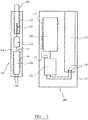
- FIG 1 shows a portable charger 100 and an aerosol generating device 102.
- the aerosol-generating device 102 in this example is an electrically heated aerosol-generating device adapted to receive a smoking article 104 comprising an aerosol-forming substrate.
- the aerosol-generating device includes a heater 134 to heat the aerosol-forming substrate in operation.
- the user inhales on a mouthpiece portion of the smoking article 104 to draw aerosol into the user's mouth.
- the aerosol-generating device 102 is configured to be received within a cavity 112 in the portable charger 100 in order to recharge the power supply in the aerosol-generating device.
- the portable charger 100 comprises charging battery 106, charging control electronics 108, and electrical contacts 110 configured to provide electrical power to a first battery in the aerosol-generating device, from the charging battery 106, when the aerosol-generating device is in connection with the electrical contacts 110.
- the electrical contacts 110 are provided adjacent the bottom of a cavity 112. The cavity is configured to receive the aerosol-generating device 102.
- the components of the portable charger 100 are housed within the housing 116.
- the aerosol-generating device 102 comprises a first battery 126, control electronics 128 and electrical contacts 130.
- the first battery 126 of the aerosol-generating device 102 is configured to receive a supply of power from the charging battery 106 when the electrical contacts 130 are in contact with the electrical contacts 110 of the portable charger 100.
- the aerosol-generating device 102 further comprises a cavity 132 configured to receive the smoking article 104.
- a heater 134 in the form of, for example, a blade heater, is provided at the bottom of the cavity 132. In use, the user activates the aerosol-generating device 102, and power is provided from the first battery 126 via the control electronics 128 to the heater 134.
- the heater is heated to a standard operational temperature that is sufficient to generate an aerosol from the aerosol-forming substrate of the aerosol-generating article 104.
- the components of the aerosol-generating device 102 are housed within the housing 136.
- An aerosol-generating device of this type is described more fully in EP2110033 for example.
- the aerosol-forming substrate preferably comprises a tobacco-containing material containing volatile tobacco flavour compounds which are released from the substrate upon heating.
- the aerosol-forming substrate may comprise a non-tobacco material.
- the aerosol-forming substrate further comprises an aerosol former. Examples of suitable aerosol formers are glycerine and propylene glycol.
- the aerosol-forming substrate may be a solid substrate.
- the solid substrate may comprise, for example, one or more of: powder, granules, pellets, shreds, spaghettis, strips or sheets containing one or more of: herb leaf, tobacco leaf, fragments of tobacco ribs, reconstituted tobacco, homogenised tobacco, extruded tobacco and expanded tobacco.
- the aerosol-generating device 102 is an electrically heated smoking device.
- the aerosol-generating device 102 is small (conventional cigarette size) but must deliver high power over a period of just a few minutes, typically around 7 minutes for a single smoking session.
- the second battery may then need to be returned to the portable charger 100 for recharging. Recharging is desirably completed, at least to a level sufficient to allow for another complete smoking experience, in a matter of a few minutes and preferably less than 6 minutes.
- the charging battery 106 in the portable charger is configured to hold sufficient charge to recharge the second battery 126 several times before needing recharging itself. This provides the user with a portable system that allows for several smoking sessions before recharging from a mains outlet is required.
- the charging battery need not be frequently replaced.
- the second battery has a useful life of at least one year, equating to around 8000 charge/discharge cycles for a typical user.
- a lithium iron phosphate (LiFePO4) battery chemistry may be used, as in this example.
- the first battery 126 in this example has a cylindrical shape, with a diameter of 10mm and a length of 37mm. This battery is able to undergo 8000 cycles of charge/discharge at more than 900J per cycle.
- the average charging rate may be up to 12C.
- a charging rate of 1C means that the battery is fully charged from zero charge to full charge in one hour and a charging rate of 2C means that the battery is fully charged from zero charge to full charge in half an hour.
- the battery capacity is in the region of 125mAh.
- the maximum charging current can range from 980mA to 1.5A. Discharging is performed using 1 millisecond pulses of up to 4A. At typical operating temperature the discharging rate is around 13C. As an alternative, a lithium titanate battery may be used for the second battery.
- the charging battery 106 in the portable charger 100 is a lithium cobalt oxide (LiCoO2) battery of the prismatic type.
- the charging battery has a capacity of around 2900mAh, over ten times the capacity of the first battery.
- the first battery may be charged from the charging battery at a rate between 2C and 16C.
- Discharging the charging battery at a rate of 1C provides a charging rate of over 10C to the first battery.
- Charging of the charging battery can be performed from a mains supply, at a rate between 0 and 1.5C, and typically at a rate of around 0.5C to maximise battery life.
- a lithium cobalt oxide battery provides a higher battery voltage than lithium iron phosphate, allowing the charging of a lithium iron phosphate battery from a single lithium cobalt oxide battery.
- Both the first battery 126 and the charging battery 106 have an associated battery heater assembly.
- Electrical heater 140 surrounds the first battery 126 and is controlled by low-temperature microcontroller 142.
- Charging battery heater 144 surrounds charging battery 106 and is controlled by a second low-temperature microcontroller 146.
- FIG 2a is a schematic cross-section of a battery heater assembly surrounding the first battery 126 shown in Figure 1 .
- Figure 2b is a disassembled view of the heater and insulation layers in the battery heater assembly of Figure 2a .
- the battery heater assembly comprises a first battery heater 140 that is a foil wrapped around the battery 126.
- electrical connections 141, 143 provide electrical current to the foil heater 140.
- the supply of power to the heater 140 will be described in greater detail below.
- Surrounding the foil heater 140 is an infrared reflective layer, which may be provided as a foil or coating.
- An insulating layer 160 is provided around the reflective layer.
- the heater 140, reflective layer 150 and insulating layer 160 may be provided as a co-laminated structure.
- the reflective layer reduces radiative heat losses from the battery.
- the insulating layer reduces conductive heat losses from the battery.
- the battery heater assembly includes two temperature sensors.
- a first temperature sensor 200 is provided between the battery 126 and the battery heater 140.
- a second temperature sensor 210 is provided outside the insulating layer 160. The output from the two temperature sensors is used in the control of the power supplied to the battery heater 140 by the microcontroller 142.
- the insulating layer 160 is formed from glass wool and has a thickness of 3mm.
- the reflective layer 150 is an aluminium foil having a thickness of 0.02 mm.
- the foil heater 140 comprises a substrate of polyimide onto which resistive copper layer is laminated.
- the temperature sensors 200, 210 are thermistors.
- Figure 2a and 2b illustrate the battery heater assembly for the first battery 126.
- An identical battery heater assembly is provided for the charging battery 106.
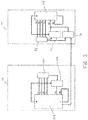
- FIG 3 the control elements of a EESD temperature control system in a system as illustrated in Figure 1 .
- the aerosol-generating device 102 comprises first battery 126, surrounded by the battery heater assembly described with reference to Figure 2a but not shown in Figure 3 for clarity.
- the microcontroller 142 is an industrial grade microcontroller that operates at temperatures down to -40 degrees Celsius.
- the microcontroller 142 is connected to the first temperature sensor 200 through connections T1 and T2 and is connected to the second temperature sensor through connections T3 and T4. Power is provided to the heater assembly from the first battery 126 through connections H1 and H2.
- the microcontroller 142 controls the supply of current to the heater assembly through connection H2 by controlling switch 147. Based on the output of the temperature sensors 200 and 210, the microcontroller closes or opens switch 147.
- the amount of power provided to the heater assembly, and hence the temperature of the first battery 126 is controlled by varying the duty cycle of the operation of the switch 147.
- the temperature of the battery can be maintained at or above a desired temperature.
- the desired temperature is 10 degrees Celsius and a control process is described in more detail below, with reference to Figure 6 .
- a EESD temperature control system is also provided for the portable charger 100, which operates in an identical manner.
- the charging battery 106 is provided with a similar battery heater assembly, as described with reference to Figures 2a and 2b .
- the microcontroller 146 is also an industrial grade microcontroller that operates at temperatures down to -40 degrees Celsius.
- the microcontroller 146 is connected to a first temperature sensor 200 through connections T1 and T2 and is connected to a second temperature sensor through connections T3 and T4.
- Power is provided to the heater assembly from the charging battery 106 through connections H1 and H2.
- the microcontroller 146 controls the supply of current to the heater assembly through connection H2 by controlling switch 149. Based on the output of the temperature sensors, the microcontroller closes or opens switch 149.
- the amount of power provided to the heater assembly, and hence the temperature of the charging battery 106 is controlled by varying the duty cycle of the operation of the switch 149. Using feedback from the temperature sensors 200 and 210, the temperature of the charging battery can be maintained at or above a desired temperature.
- a second switch 170 is provided which allows for selective connection of the charging battery to the battery heater for the first battery.
- the microcontroller 142 controls the supply of current to the heater assembly through connection H2 by controlling both switch 147 and switch 170. If the aerosol-generating device is connected to the portable charger the microcontroller 142 may disconnect the first battery 126 from the first battery heater but may allow connection of the charging battery to the first battery heater.
- the charging battery may be at a higher temperature than the first battery and so may be able to deliver more power.
- the charging battery also typically has greater capacity than the first battery.
- Figure 4 illustrates a basic control method using two temperature sensors.
- T 1 The output from the first temperature sensor, referred to as T 1
- T 2 the output from the second temperature sensor 210, referred to as T 2
- step 310 the value of T 1 is compared to a first threshold value, T a , in this case 10 degrees Celsius. If T 1 is not less than T a then the process return to step 300 for another cycle. If T 1 is less than T a then the process proceeds to step 320.
- the value of T 2 is compared to a first threshold value, T b , in this case 12 degrees Celsius. If T 2 is not less than T b then the process return to step 300 for another cycle.
- step 330 the battery heater is activated by providing a current pulse to the battery heater.
- the process is then repeated by returning to step 300.
- the advantage of having a second temperature sensor sensing ambient temperature is that thermal overshoot can be more easily avoided. Normal operation of the device will generate some heat. If the ambient temperature is above a threshold level, then active heating of the battery may be not be necessary even if the battery temperature is initially below the first threshold. For example, if the device is taken from a cold environment to a warm, indoor environment just prior to use, the battery temperature may be below the optimal temperature but passive heating of the battery may be sufficient. Active heating of the battery may both be a waste of energy and lead to possible thermal overshoot.
- Figure 5 illustrates an alternative configuration of a EESD temperature control system for an aerosol-generating device and a portable charger.
- the embodiment of Figure 4 uses inductive heating to heat the first battery within the aerosol-generating device using a coil held within the charger.
- the aerosol-generating device 402 is illustrated schematically and comprises a first battery 404 and an aerosol-generating element 406.
- the portable charger 400 comprises a charging battery 408.
- the aerosol-generating device 402 is held in a cavity 410 in the portable charger.
- a coil 412 in the portable charger surrounds a portion of the cavity 412 so that it surrounds a portion of the first battery 404 when the aerosol-generating device 402 is held in the cavity 410.
- the aerosol-generating device has a susceptor element (not shown) which is integral or close to the first battery.
- the coil 412 is connected to a high frequency AC source 418, which is powered by the charging battery 408.
- the portable charger also comprises a thermistor 416 adjacent to the cavity 410 to sense the temperature of the first battery or the housing of the aerosol-generating device.
- a microcontroller 414 is connected to the thermistor 416, the charging battery 408 and the high frequency AC source 418. Based on the output of the thermistor 416, the microcontroller 414 allows the supply of high frequency alternating current to the coil 412. When the temperature sensed by the temperature sensor falls below 10 degrees Celcius the AC source is switched on by the microcontroller. When a high frequency alternating current is supplied to the coil it causes inductive heating of the susceptor and so heats the first battery. Using feedback from the tthermistor 416, the temperature of the battery can be maintained at or above a desired temperature.
- the portable charger may continually monitor the temperature sensed by the temperature sensor and operate the coil to prevent the temperature ever falling below 10 degrees Celsius. The same process may be carried out for the charging battery.
- the charging battery may be configured to operate at low temperatures and the battery heating system only activated following a user input.
- the coil 412 could be configured to act as a resistive heater that heats the cavity 410, and so heats the first battery 404 when it is in the cavity.
- a DC current could be applied to the coil 412, or another form of resistive heater, to heat the cavity by Joule heating.
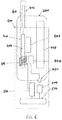
- FIG. 6 illustrates a further alternative configuration in which a dedicated warming accessory is provided separate to the portable charger.
- the warming accessory 500 is a pouch that receives both the portable charger and the aerosol-generating device together and operates to heat the battery in the aerosol-generating device inductively.
- the aerosol-generating device 402 in Figure 6 is identical to the aerosol-generating device shown in Figure 5 and comprises a first battery 404 and an aerosol-generating element 406.
- the aerosol-generating device has a susceptor element (not shown) which is integral or close to the first battery.
- the portable charger 440 comprises a charging battery 448.
- the aerosol-generating device 402 is held in a cavity 410 in the portable charger.
- the portable charger also comprises a temperature sensor 446 adjacent to the cavity 410 to sense the temperature of the first battery or the housing of the aerosol-generating device.
- a microcontroller 444 is connected to the temperature sensor 416, the charging battery 448 and to an interface 450 with the warming accessory 500.
- the warming accessory 500 comprises an accessory EESD 502, a microcontroller 504, a high frequency AC source 506 and a coil 508.
- the coil is positioned within the warming accessory at a position adjacent the first battery when the aerosol-generating device is received in the warming accessory.
- the coil 508 is a planar coil.
- the microcontroller 504 is connected to the accessory EESD 502 and to the high frequency AC source 506.
- the microcontroller 504 is also connected to the interface 450 and receives signals through the interface 450 based on the output from the temperature sensor 446 in the portable charger.
- the interface allows for data exchange between the warming accessory and the portable charger and may be a micro USB connection for example.
- the warming accessory may exchange information with the portable charger through a wireless connection, such as Bluetooth.
- a wireless connection such as Bluetooth.
- the microcontroller switched the AC source on.
- a high frequency alternating current is supplied to the coil it causes inductive heating of the susceptor and so heats the first battery.
- the temperature of the battery can be maintained at or above a desired temperature.
- the same arrangement can be provided to heat the charging battery in the portable charger.
- the warming accessory may comprise thermal insulation that reduce heat loss both from the accessory EESD 502 but that also from the portable charger and the aerosol-generating device.
- the warming accessory could comprise a resistive heater configured to heat the interior of the accessory and any charger and aerosol-generating device received in the accessory.
- the resistive heater could be controlled based on feedback from the temperature sensor 446, in the manner described with reference to Figure 6 .
- Systems in accordance with the invention result in an improved and more consistent user experience compared to systems without battery temperature regulation.
- battery warming may reduce the energy available for aerosol-generation or battery charging, the advantage of providing a satisfying delivery of aerosol to the user regardless of the ambient conditions is more critical.
Claims (18)
- Aerosolerzeugungssystem, aufweisend:ein elektrisch betriebenes aerosolerzeugendes Element (406);eine erste elektrochemischeEnergiespeichervorrichtung (EESD) (106, 126), die ausgelegt ist, das aerosolerzeugende Element mit elektrische Energie zu versorgen; undein EESD-Temperatursteuerungssystem, das zumindest einen Temperatursensor (200, 210) aufweist, der zum Erfassen einer Temperatur der ersten EESD positioniert ist, und eine elektrische Heizvorrichtung (140, 144), die zum Erwärmen der ersten EESD ausgelegt ist, wobei das EESD-Temperatursteuerungssystem die elektrische Heizvorrichtung abhängig von einer Ausgabe von dem zumindest einen Temperatursensor betreibt.
- Aerosolerzeugungssystem nach Anspruch 1, wobei das System eine tragbare Aerosolerzeugungsvorrichtung (102) aufweist und wobei die Aerosolerzeugungsvorrichtung das aerosolerzeugende Element (406), die erste EESD (106, 126) und das EESD-Temperatursteuerungssystem aufweist.
- Aerosolerzeugungssystem nach Anspruch 2, wobei das EESD-Temperatursteuerungssystem mit einem Leistungssteller verbunden oder einstückig damit ausgebildet ist, der ausgelegt ist, eine elektrische Energieversorgung von der ersten EESD (106, 126) an das aerosolerzeugende Element zu regeln, wobei der Leistungssteller ausgelegt ist, die Energieversorgung von der ersten EESD an das aerosolerzeugende Element abhängig von einer Ausgabe von dem zumindest einen Temperatursensor (200, 210) zu verhindern.
- Aerosolerzeugungssystem nach Anspruch 2 oder Anspruch 3, wobei die erste EESD (106, 126) elektrische Anschlüsse besitzt und wobei das EESD-Temperatursteuerungssystem mit den ersten EESD-Anschlüssen verbunden ist, sodass die elektrische Heizvorrichtung (140, 144) durch die erste EESD mit Energie versorgt werden kann.
- Aerosolerzeugungssystem nach Anspruch 1, aufweisend:eine Aerosolerzeugungsvorrichtung (102); undein Zubehörteil, wobei das Zubehörteil eine Zubehörteil-EESD (502) aufweist und wobei die Aerosolerzeugungsvorrichtung und das Zubehörteil elektrisch verbunden sein können, und wobei das System ausgelegt ist, der Zubehörteil-EESD zu ermöglichen, die elektrische Heizvorrichtung (140, 144) mit Energie zu versorgen, wenn die Aerosolerzeugungsvorrichtung und das Zubehörteil elektrisch verbunden sind.
- Aerosolerzeugungssystem nach Anspruch 5, wobei das EESD-Temperatursteuerungssystem zumindest teilweise in dem Zubehörteil (502) enthalten ist.
- Aerosolerzeugungssystem nach Anspruch 6, wobei das Zubehörteil (502) eine Wechselstromquelle (506) und eine Induktionsspule (508) aufweist, die ausgelegt sind, die erste EESD (106, 126) induktiv zu erwärmen.
- Aerosolerzeugungssystem nach Anspruch 5, 6 oder 7, wobei das Zubehörteil (502) eine tragbare Heizvorrichtung ist.
- Aerosolerzeugungssystem nach Anspruch 5, 6 oder 7, wobei das Zubehörteil (502) ein tragbares Ladegerät ist und wobei das System ausgelegt ist, das Laden der ersten EESD (106, 126) von der Zubehörteil-EESD (502) zu ermöglichen.
- Aerosolerzeugungssystem nach Anspruch 9, ferner aufweisend eine Heizvorrichtung, die ausgelegt ist, das tragbare Ladegerät und die Aerosolerzeugungsvorrichtung (102) aufzunehmen, wobei die Heizvorrichtung eine Heizvorrichtung-EESD aufweist und wobei die Aerosolerzeugungsvorrichtung oder das tragbare Ladegerät und die Heizvorrichtung elektrisch verbunden sein können, und wobei das System ausgelegt ist, der Heizvorrichtung-EESD zu ermöglichen, die elektrische Heizvorrichtung mit Energie zu versorgen, wenn die Aerosolerzeugungsvorrichtung oder das tragbare Ladegerät und die Heizvorrichtung elektrisch verbunden sind.
- Aerosolerzeugungssystem nach einem der Ansprüche 5 bis 10, wobei das Zubehörteil (502) ein Zubehörteil-EESD-Temperatursteuerungssystem aufweist, das zumindest einen Zubehör-Temperatursensor (446) aufweist, der zum Erfassen einer Temperatur der Zubehörteil-EESD positioniert ist, und eine zweite elektrische Heizvorrichtung, die zum Erwärmen der Zubehörteil-EESD ausgelegt ist, wobei das Zubehörteil-EESD-Temperatursteuerungssystem die zweite elektrische Heizvorrichtung abhängig von einer Ausgabe von dem zumindest einen Zubehörteil-Temperatursensor betreibt.
- Aerosolerzeugungssystem nach Anspruch 11, wenn abhängig von Anspruch 9 oder 10, wobei das Zubehörteil-EESD-Temperatursteuerungssystem mit einem Leistungssteller verbunden oder einstückig damit ausgebildet ist, der ausgelegt ist, eine elektrische Energieversorgung von der Zubehörteil-EESD (502) an die Aerosolerzeugungsvorrichtung zu regeln, wobei der Leistungssteller ausgelegt ist, die Energieversorgung von der Zubehörteil-EESD an die Aerosolerzeugungsvorrichtung (102) abhängig von einer Ausgabe von dem zumindest einen Zubehörteil-Temperatursensor zu verhindern.
- Aerosolerzeugungssystem nach Anspruch 11 oder Anspruch 12, wobei die Zubehörteil-EESD (502) elektrische Anschlüsse besitzt und wobei das Zubehörteil-EESD-Temperatursteuerungssystem mit den Zubehörteil-EESD-Anschlüssen verbunden ist, sodass die zweite elektrische Heizvorrichtung durch die Zubehörteil-EESD mit Energie versorgt werden kann.
- Aerosolerzeugungssystem nach einem der vorstehenden Ansprüche, ferner aufweisend eine Wärmeisolierung (160), die die erste EESD (106, 126) umgibt.
- Aerosolerzeugungssystem nach Anspruch 14, wobei die Wärmeisolierung (160) eine infrarotreflektierende Schicht (150) aufweist.
- Aerosolerzeugungssystem nach Anspruch 14 oder Anspruch 15, wobei der zumindest eine Temperatursensor einen ersten Temperatursensor (200) aufweist, der zwischen der ersten EESD (106, 126) und der Wärmeisolierung (160) positioniert ist, und einen zweiten Temperatursensor (210), der außerhalb der Wärmeisolierung positioniert ist, und wobei die elektrische Heizvorrichtung (140, 144) abhängig von einer Ausgabe vom ersten Temperatursensor und einer Ausgabe vom zweiten Temperatursensor aktiviert wird.
- Aerosolerzeugungssystem nach Anspruch 2, aufweisend:
ein tragbares Ladegerät (100), wobei das tragbare Ladegerät eine Lade-EESD (502) aufweist und wobei die Aerosolerzeugungsvorrichtung und das tragbare Ladegerät elektrisch verbunden sein können, um das Aufladen der ersten EESD (106, 126) von der Lade-EESD zu ermöglichen, und wobei das tragbare Ladegerät ein Lade-EESD-Temperatursteuerungssystem aufweist, das zumindest einen Lade-Temperatursensor aufweist, der zum Erfassen einer Temperatur der Lade-EESD positioniert ist, und eine zweite elektrische Heizvorrichtung, die zum Erwärmen der Lade-EESD ausgelegt ist, wobei das Lade-EESD-Temperatursteuerungssystem die zweite elektrische Heizvorrichtung abhängig von einer Ausgabe von dem zumindest einen Lade-Temperatursensor betreibt. - Verfahren zum Steuern des Betriebs einer elektrisch betriebenen Aerosolerzeugungsvorrichtung (102), wobei die elektrisch betriebene Aerosolerzeugungsvorrichtung ein elektrisch betriebenes aerosolerzeugendes Element (406) aufweist; eine erste elektrochemische Energiespeichervorrichtung (EESD) (106, 126), die ausgelegt ist, das aerosolerzeugende Element (406) mit Energie zu versorgen und ein EESD-Temperatursteuerungssystem, das zumindest einen Temperatursensor (200, 210) aufweist, der zum Erfassen einer Temperatur der ersten EESD positioniert ist, und eine elektrische Heizvorrichtung (140, 144), die zum Erwärmen der ersten EESD ausgelegt ist, das Verfahren umfassend:
Überwachen einer Ausgabe des zumindest einen Temperatursensors und das Betreiben der elektrischen Heizvorrichtung, wenn die Ausgabe des zumindest einen Temperatursensors unter einem ersten Schwellenwert liegt, und Verhindern einer Energieversorgung von der ersten EESD an das elektrisch betriebene aerosolerzeugende Element, bis die Ausgabe des zumindest einen Temperatursensors gleich dem oder über einem zweiten Schwellenwert liegt.
Applications Claiming Priority (2)
| Application Number | Priority Date | Filing Date | Title |
|---|---|---|---|
| EP16176953 | 2016-06-29 | ||
| PCT/EP2017/064663 WO2018001746A1 (en) | 2016-06-29 | 2017-06-15 | Battery powered aerosol-generating device comprising a temperature dependent battery pre-heating |
Publications (2)
| Publication Number | Publication Date |
|---|---|
| EP3478101A1 EP3478101A1 (de) | 2019-05-08 |
| EP3478101B1 true EP3478101B1 (de) | 2021-03-17 |
Family
ID=56321777
Family Applications (1)
| Application Number | Title | Priority Date | Filing Date |
|---|---|---|---|
| EP17731854.0A Active EP3478101B1 (de) | 2016-06-29 | 2017-06-15 | Batteriebetriebene aerosolerzeugungs-vorrichtung mit temperaturabhängiger batterievorheizung |
Country Status (8)
| Country | Link |
|---|---|
| US (1) | US11533953B2 (de) |
| EP (1) | EP3478101B1 (de) |
| JP (1) | JP7069051B2 (de) |
| KR (1) | KR102526864B1 (de) |
| CN (1) | CN109310153B (de) |
| CA (1) | CA3022233A1 (de) |
| RU (1) | RU2736025C2 (de) |
| WO (1) | WO2018001746A1 (de) |
Families Citing this family (33)
| Publication number | Priority date | Publication date | Assignee | Title |
|---|---|---|---|---|
| US10667558B2 (en) * | 2016-11-29 | 2020-06-02 | Altria Client Services Llc | Vaporizer for an aerosol-generating system and vaporizing method |
| US10653185B2 (en) * | 2016-11-29 | 2020-05-19 | Altria Client Services Llc | Aerosol-generating system and method of dispensing liquid aerosol-forming substrate with pumped air |
| CN111869939A (zh) * | 2017-01-18 | 2020-11-03 | 韩国烟草人参公社 | 充电系统 |
| US11191921B1 (en) * | 2018-02-28 | 2021-12-07 | Dynavap, LLC | Convection aromatherapy device |
| RU2757244C1 (ru) * | 2018-05-31 | 2021-10-12 | Джапан Тобакко Инк. | Устройство для генерации аромата |
| JP2020058236A (ja) * | 2018-10-04 | 2020-04-16 | 日本たばこ産業株式会社 | 吸引成分生成装置、制御回路、吸引成分生成装置の制御方法および制御プログラム |
| JP7204909B2 (ja) * | 2018-11-30 | 2023-01-16 | 昂納自動化技術(深▲ゼン▼)有限公司 | 電子タバコの制御方法 |
| GB201903247D0 (en) * | 2019-03-11 | 2019-04-24 | Nicoventures Trading Ltd | Aerosol provision device |
| AU2020235034B2 (en) * | 2019-03-11 | 2023-09-28 | Nicoventures Trading Limited | Apparatus for aerosol generating device |
| KR20210129094A (ko) * | 2019-03-11 | 2021-10-27 | 니코벤처스 트레이딩 리미티드 | 에어로졸 제공 디바이스 |
| KR102232204B1 (ko) * | 2019-03-19 | 2021-03-25 | 주식회사 케이티앤지 | 에어로졸 생성장치 및 이의 배터리 수명 추정방법 |
| JP6678936B1 (ja) | 2019-05-31 | 2020-04-15 | 日本たばこ産業株式会社 | エアロゾル吸引器用の制御装置及びエアロゾル吸引器 |
| JP6625258B1 (ja) * | 2019-05-31 | 2019-12-25 | 日本たばこ産業株式会社 | エアロゾル吸引器、エアロゾル吸引器用の制御装置、エアロゾル吸引器の制御方法及びプログラム |
| JP6613008B1 (ja) | 2019-05-31 | 2019-11-27 | 日本たばこ産業株式会社 | エアロゾル吸引器用の制御装置及びエアロゾル吸引器 |
| CN110138067A (zh) * | 2019-06-03 | 2019-08-16 | 孙亦博 | 一种供电电源系统 |
| CN113840550A (zh) * | 2019-06-12 | 2021-12-24 | 菲利普莫里斯生产公司 | 包括三维码的气溶胶生成制品 |
| US20230105496A1 (en) | 2020-01-09 | 2023-04-06 | Philip Morris Products S.A. | Flexible heater and electronics |
| KR20210092082A (ko) * | 2020-01-15 | 2021-07-23 | 주식회사 케이티앤지 | 자동으로 가열 동작을 수행하는 에어로졸 생성 장치 |
| KR102354965B1 (ko) | 2020-02-13 | 2022-01-24 | 주식회사 케이티앤지 | 에어로졸 생성 장치 및 그의 동작 방법 |
| CN111387557A (zh) * | 2020-03-19 | 2020-07-10 | 四川三联新材料有限公司 | 多层隔热材料、其制备方法及其应用和加热卷烟器具 |
| WO2022002938A1 (en) * | 2020-06-30 | 2022-01-06 | Jt International S.A. | Aerosol generation device comprising temperature sensors and associated monitoring method |
| EP3937337B1 (de) | 2020-07-09 | 2022-11-09 | Japan Tobacco Inc. | Stromversorgungseinheit für aerosolinhalator aufweisend einen temperatursensor |
| JP6864769B1 (ja) | 2020-07-09 | 2021-04-28 | 日本たばこ産業株式会社 | エアロゾル吸引器の電源ユニット |
| KR20230022446A (ko) * | 2020-07-14 | 2023-02-15 | 필립모리스 프로덕츠 에스.에이. | 다중 기능 배터리 히터를 갖는 전자 장치 |
| JP2023533791A (ja) * | 2020-07-14 | 2023-08-04 | フィリップ・モーリス・プロダクツ・ソシエテ・アノニム | 移動可能な電池加熱構成を有する電子装置 |
| US20230301365A1 (en) * | 2020-07-21 | 2023-09-28 | Philip Morris Products S.A. | Aerosol generator with dual battery heating arrangement |
| CN112291874B (zh) * | 2020-09-11 | 2022-05-13 | 中国科学技术大学 | 一种用于合金相变材料烟用热源的电磁加热装置 |
| KR102463898B1 (ko) * | 2020-11-11 | 2022-11-03 | 주식회사 케이티앤지 | 에어로졸 생성장치 및 그 동작방법 |
| CN114639925B (zh) * | 2020-12-16 | 2023-09-05 | 比亚迪股份有限公司 | 一种极耳热封设备和极耳热封方法 |
| CN117255629A (zh) * | 2021-04-26 | 2023-12-19 | 日本烟草产业株式会社 | 香味吸取器 |
| WO2022239370A1 (ja) | 2021-05-10 | 2022-11-17 | 日本たばこ産業株式会社 | エアロゾル生成装置の電源ユニット |
| WO2022239371A1 (ja) | 2021-05-10 | 2022-11-17 | 日本たばこ産業株式会社 | エアロゾル生成装置の電源ユニット |
| KR20230114549A (ko) * | 2022-01-25 | 2023-08-01 | 주식회사 케이티앤지 | 에어로졸 생성장치 |
Family Cites Families (28)
| Publication number | Priority date | Publication date | Assignee | Title |
|---|---|---|---|---|
| JPH08308129A (ja) * | 1995-05-08 | 1996-11-22 | Matsushita Electric Ind Co Ltd | 充電装置 |
| JPH09147813A (ja) * | 1995-11-29 | 1997-06-06 | Matsushita Electric Ind Co Ltd | 電池および電池用外装材 |
| JP2000228230A (ja) * | 1999-02-08 | 2000-08-15 | Nec Corp | 電池パック |
| CN101416330A (zh) * | 2003-10-14 | 2009-04-22 | 布莱克和戴克公司 | 二次电池的保护方法、保护电路和保护器件、电动工具、充电器和适合在电池组中提供保护以防故障状况的电池组 |
| JP4768273B2 (ja) * | 2005-01-12 | 2011-09-07 | Necエナジーデバイス株式会社 | 電池パック |
| CN201041817Y (zh) * | 2007-01-16 | 2008-03-26 | 研华股份有限公司 | 电池模块的过温保护装置 |
| WO2008093738A1 (ja) * | 2007-02-02 | 2008-08-07 | Japan Tobacco Inc. | 喫煙用具 |
| JP2008269855A (ja) * | 2007-04-18 | 2008-11-06 | Nec Access Technica Ltd | 電池パック及びそれを用いた電子機器 |
| US8129955B2 (en) * | 2007-07-13 | 2012-03-06 | Black & Decker Inc. | Reset mechanism for a battery pack |
| EP2110033A1 (de) | 2008-03-25 | 2009-10-21 | Philip Morris Products S.A. | Verfahren zum Steuern der Bildung von Rauchbestandteilen in einem elektrischen Aerosolerzeugungssystem |
| CN201294250Y (zh) * | 2008-11-17 | 2009-08-19 | 浙江绿源电动车有限公司 | 带恒温加热控制的蓄电池充电装置 |
| CN201616494U (zh) * | 2009-12-25 | 2010-10-27 | 天津市飞科电动车有限公司 | 电动车蓄电池低温温度补偿装置 |
| TWI382572B (zh) * | 2010-02-12 | 2013-01-11 | Asia Vital Components Co Ltd | Used in the heating structure of the battery and the device and cooling auxiliary module |
| KR101184752B1 (ko) * | 2010-06-03 | 2012-09-20 | 정윤이 | 배터리 팩 그리고 배터리 팩의 충전 방법 |
| US8978663B2 (en) | 2010-12-06 | 2015-03-17 | Kyle D. Newton | Charger package for electronic cigarette components |
| KR20140063506A (ko) * | 2011-02-09 | 2014-05-27 | 새미 카푸아노 | 가변전력제어 전자담배 |
| PL2797445T3 (pl) * | 2011-12-30 | 2016-11-30 | Urządzenie do tworzenia aerozolu z ulepszonym rozkładem temperatury | |
| WO2014182097A1 (ko) | 2013-05-08 | 2014-11-13 | 주식회사 엘지화학 | 배터리 예열 시스템 및 이를 이용한 배터리 예열방법 |
| US20140333267A1 (en) * | 2013-05-10 | 2014-11-13 | Fairchild Semiconductor Corporation | Heated accelerated battery charging |
| WO2014190079A2 (en) * | 2013-05-22 | 2014-11-27 | Njoy, Inc. | Compositions, devices, and methods for nicotine aerosol delivery |
| CN203632311U (zh) * | 2013-12-16 | 2014-06-04 | 天宇通讯科技(昆山)有限公司 | 带加热装置的移动电源 |
| GB201413028D0 (en) * | 2014-02-28 | 2014-09-03 | Beyond Twenty Ltd | Beyond 5 |
| TWI681691B (zh) * | 2014-04-30 | 2020-01-01 | 瑞士商菲利浦莫里斯製品股份有限公司 | 電熱式氣溶膠產生系統、裝置及其控制方法 |
| GB2528711B (en) | 2014-07-29 | 2019-02-20 | Nicoventures Holdings Ltd | E-cigarette and re-charging pack |
| CN104242390B (zh) * | 2014-09-01 | 2016-12-07 | 广东欧珀移动通信有限公司 | 一种充电方法、充电电路和移动终端 |
| US20160359207A1 (en) * | 2015-06-08 | 2016-12-08 | Abominable Labs, Llc | Thermally-protected chemical-cell battery system |
| WO2017084489A1 (zh) * | 2015-11-18 | 2017-05-26 | 常州聚为智能科技有限公司 | 烟嘴、带有该烟嘴的雾化器及其电子烟 |
| CN205211892U (zh) * | 2015-12-22 | 2016-05-04 | 袁元 | 一种可控温的电池加热装置 |
-
2017
- 2017-06-15 JP JP2018565051A patent/JP7069051B2/ja active Active
- 2017-06-15 KR KR1020187033573A patent/KR102526864B1/ko active IP Right Grant
- 2017-06-15 CN CN201780035069.XA patent/CN109310153B/zh active Active
- 2017-06-15 US US16/310,224 patent/US11533953B2/en active Active
- 2017-06-15 CA CA3022233A patent/CA3022233A1/en active Pending
- 2017-06-15 WO PCT/EP2017/064663 patent/WO2018001746A1/en unknown
- 2017-06-15 RU RU2019102193A patent/RU2736025C2/ru active
- 2017-06-15 EP EP17731854.0A patent/EP3478101B1/de active Active
Non-Patent Citations (1)
| Title |
|---|
| None * |
Also Published As
| Publication number | Publication date |
|---|---|
| WO2018001746A1 (en) | 2018-01-04 |
| CN109310153A (zh) | 2019-02-05 |
| KR102526864B1 (ko) | 2023-04-28 |
| US11533953B2 (en) | 2022-12-27 |
| RU2019102193A3 (de) | 2020-09-24 |
| RU2019102193A (ru) | 2020-07-29 |
| JP2019525737A (ja) | 2019-09-12 |
| JP7069051B2 (ja) | 2022-05-17 |
| CN109310153B (zh) | 2024-01-02 |
| CA3022233A1 (en) | 2018-01-04 |
| US20190320717A1 (en) | 2019-10-24 |
| EP3478101A1 (de) | 2019-05-08 |
| RU2736025C2 (ru) | 2020-11-11 |
| KR20190024880A (ko) | 2019-03-08 |
Similar Documents
| Publication | Publication Date | Title |
|---|---|---|
| EP3478101B1 (de) | Batteriebetriebene aerosolerzeugungs-vorrichtung mit temperaturabhängiger batterievorheizung | |
| EP3723525B1 (de) | Aerosolbildende vorrichtung mit feedbacksteuerung | |
| JP7112202B2 (ja) | モジュールおよび電気的に動作するエアロゾル発生システムを含むキット | |
| EP2727619B1 (de) | Elektronische Verdampfungsvorrichtung mit niedriger Temperatur und Verfahren | |
| EP4111891A1 (de) | Aerosolerzeugungsvorrichtung und verfahren zur steuerung eines heizers einer aerosolerzeugungsvorrichtung | |
| EP3490391A1 (de) | Aerosolerzeugungssystem mit einem beheizten gelbehälter |
Legal Events
| Date | Code | Title | Description |
|---|---|---|---|
| STAA | Information on the status of an ep patent application or granted ep patent |
Free format text: STATUS: UNKNOWN |
|
| STAA | Information on the status of an ep patent application or granted ep patent |
Free format text: STATUS: THE INTERNATIONAL PUBLICATION HAS BEEN MADE |
|
| PUAI | Public reference made under article 153(3) epc to a published international application that has entered the european phase |
Free format text: ORIGINAL CODE: 0009012 |
|
| STAA | Information on the status of an ep patent application or granted ep patent |
Free format text: STATUS: REQUEST FOR EXAMINATION WAS MADE |
|
| 17P | Request for examination filed |
Effective date: 20181221 |
|
| AK | Designated contracting states |
Kind code of ref document: A1 Designated state(s): AL AT BE BG CH CY CZ DE DK EE ES FI FR GB GR HR HU IE IS IT LI LT LU LV MC MK MT NL NO PL PT RO RS SE SI SK SM TR |
|
| AX | Request for extension of the european patent |
Extension state: BA ME |
|
| DAV | Request for validation of the european patent (deleted) | ||
| DAX | Request for extension of the european patent (deleted) | ||
| STAA | Information on the status of an ep patent application or granted ep patent |
Free format text: STATUS: EXAMINATION IS IN PROGRESS |
|
| 17Q | First examination report despatched |
Effective date: 20200720 |
|
| REG | Reference to a national code |
Ref country code: DE Ref legal event code: R079 Ref document number: 602017034763 Country of ref document: DE Free format text: PREVIOUS MAIN CLASS: A24F0047000000 Ipc: A24F0040500000 |
|
| RIC1 | Information provided on ipc code assigned before grant |
Ipc: H01M 10/657 20140101ALI20200924BHEP Ipc: H01M 10/48 20060101ALI20200924BHEP Ipc: A24F 40/50 20200101AFI20200924BHEP Ipc: A24F 40/90 20200101ALI20200924BHEP Ipc: H01M 10/44 20060101ALI20200924BHEP Ipc: A24F 40/57 20200101ALI20200924BHEP |
|
| GRAP | Despatch of communication of intention to grant a patent |
Free format text: ORIGINAL CODE: EPIDOSNIGR1 |
|
| STAA | Information on the status of an ep patent application or granted ep patent |
Free format text: STATUS: GRANT OF PATENT IS INTENDED |
|
| INTG | Intention to grant announced |
Effective date: 20201105 |
|
| GRAS | Grant fee paid |
Free format text: ORIGINAL CODE: EPIDOSNIGR3 |
|
| GRAA | (expected) grant |
Free format text: ORIGINAL CODE: 0009210 |
|
| STAA | Information on the status of an ep patent application or granted ep patent |
Free format text: STATUS: THE PATENT HAS BEEN GRANTED |
|
| AK | Designated contracting states |
Kind code of ref document: B1 Designated state(s): AL AT BE BG CH CY CZ DE DK EE ES FI FR GB GR HR HU IE IS IT LI LT LU LV MC MK MT NL NO PL PT RO RS SE SI SK SM TR |
|
| REG | Reference to a national code |
Ref country code: GB Ref legal event code: FG4D |
|
| REG | Reference to a national code |
Ref country code: CH Ref legal event code: EP |
|
| REG | Reference to a national code |
Ref country code: DE Ref legal event code: R096 Ref document number: 602017034763 Country of ref document: DE |
|
| REG | Reference to a national code |
Ref country code: IE Ref legal event code: FG4D |
|
| REG | Reference to a national code |
Ref country code: CH Ref legal event code: NV Representative=s name: MURGITROYD AND COMPANY, CH Ref country code: AT Ref legal event code: REF Ref document number: 1371381 Country of ref document: AT Kind code of ref document: T Effective date: 20210415 |
|
| REG | Reference to a national code |
Ref country code: NL Ref legal event code: FP |
|
| REG | Reference to a national code |
Ref country code: LT Ref legal event code: MG9D |
|
| PG25 | Lapsed in a contracting state [announced via postgrant information from national office to epo] |
Ref country code: NO Free format text: LAPSE BECAUSE OF FAILURE TO SUBMIT A TRANSLATION OF THE DESCRIPTION OR TO PAY THE FEE WITHIN THE PRESCRIBED TIME-LIMIT Effective date: 20210617 Ref country code: GR Free format text: LAPSE BECAUSE OF FAILURE TO SUBMIT A TRANSLATION OF THE DESCRIPTION OR TO PAY THE FEE WITHIN THE PRESCRIBED TIME-LIMIT Effective date: 20210618 Ref country code: FI Free format text: LAPSE BECAUSE OF FAILURE TO SUBMIT A TRANSLATION OF THE DESCRIPTION OR TO PAY THE FEE WITHIN THE PRESCRIBED TIME-LIMIT Effective date: 20210317 Ref country code: HR Free format text: LAPSE BECAUSE OF FAILURE TO SUBMIT A TRANSLATION OF THE DESCRIPTION OR TO PAY THE FEE WITHIN THE PRESCRIBED TIME-LIMIT Effective date: 20210317 Ref country code: BG Free format text: LAPSE BECAUSE OF FAILURE TO SUBMIT A TRANSLATION OF THE DESCRIPTION OR TO PAY THE FEE WITHIN THE PRESCRIBED TIME-LIMIT Effective date: 20210617 |
|
| REG | Reference to a national code |
Ref country code: AT Ref legal event code: MK05 Ref document number: 1371381 Country of ref document: AT Kind code of ref document: T Effective date: 20210317 |
|
| PG25 | Lapsed in a contracting state [announced via postgrant information from national office to epo] |
Ref country code: SE Free format text: LAPSE BECAUSE OF FAILURE TO SUBMIT A TRANSLATION OF THE DESCRIPTION OR TO PAY THE FEE WITHIN THE PRESCRIBED TIME-LIMIT Effective date: 20210317 Ref country code: RS Free format text: LAPSE BECAUSE OF FAILURE TO SUBMIT A TRANSLATION OF THE DESCRIPTION OR TO PAY THE FEE WITHIN THE PRESCRIBED TIME-LIMIT Effective date: 20210317 Ref country code: LV Free format text: LAPSE BECAUSE OF FAILURE TO SUBMIT A TRANSLATION OF THE DESCRIPTION OR TO PAY THE FEE WITHIN THE PRESCRIBED TIME-LIMIT Effective date: 20210317 |
|
| PG25 | Lapsed in a contracting state [announced via postgrant information from national office to epo] |
Ref country code: CZ Free format text: LAPSE BECAUSE OF FAILURE TO SUBMIT A TRANSLATION OF THE DESCRIPTION OR TO PAY THE FEE WITHIN THE PRESCRIBED TIME-LIMIT Effective date: 20210317 Ref country code: EE Free format text: LAPSE BECAUSE OF FAILURE TO SUBMIT A TRANSLATION OF THE DESCRIPTION OR TO PAY THE FEE WITHIN THE PRESCRIBED TIME-LIMIT Effective date: 20210317 Ref country code: LT Free format text: LAPSE BECAUSE OF FAILURE TO SUBMIT A TRANSLATION OF THE DESCRIPTION OR TO PAY THE FEE WITHIN THE PRESCRIBED TIME-LIMIT Effective date: 20210317 Ref country code: SM Free format text: LAPSE BECAUSE OF FAILURE TO SUBMIT A TRANSLATION OF THE DESCRIPTION OR TO PAY THE FEE WITHIN THE PRESCRIBED TIME-LIMIT Effective date: 20210317 Ref country code: AT Free format text: LAPSE BECAUSE OF FAILURE TO SUBMIT A TRANSLATION OF THE DESCRIPTION OR TO PAY THE FEE WITHIN THE PRESCRIBED TIME-LIMIT Effective date: 20210317 |
|
| PG25 | Lapsed in a contracting state [announced via postgrant information from national office to epo] |
Ref country code: RO Free format text: LAPSE BECAUSE OF FAILURE TO SUBMIT A TRANSLATION OF THE DESCRIPTION OR TO PAY THE FEE WITHIN THE PRESCRIBED TIME-LIMIT Effective date: 20210317 Ref country code: SK Free format text: LAPSE BECAUSE OF FAILURE TO SUBMIT A TRANSLATION OF THE DESCRIPTION OR TO PAY THE FEE WITHIN THE PRESCRIBED TIME-LIMIT Effective date: 20210317 Ref country code: PL Free format text: LAPSE BECAUSE OF FAILURE TO SUBMIT A TRANSLATION OF THE DESCRIPTION OR TO PAY THE FEE WITHIN THE PRESCRIBED TIME-LIMIT Effective date: 20210317 Ref country code: PT Free format text: LAPSE BECAUSE OF FAILURE TO SUBMIT A TRANSLATION OF THE DESCRIPTION OR TO PAY THE FEE WITHIN THE PRESCRIBED TIME-LIMIT Effective date: 20210719 Ref country code: IS Free format text: LAPSE BECAUSE OF FAILURE TO SUBMIT A TRANSLATION OF THE DESCRIPTION OR TO PAY THE FEE WITHIN THE PRESCRIBED TIME-LIMIT Effective date: 20210717 |
|
| REG | Reference to a national code |
Ref country code: DE Ref legal event code: R097 Ref document number: 602017034763 Country of ref document: DE |
|
| PLBE | No opposition filed within time limit |
Free format text: ORIGINAL CODE: 0009261 |
|
| STAA | Information on the status of an ep patent application or granted ep patent |
Free format text: STATUS: NO OPPOSITION FILED WITHIN TIME LIMIT |
|
| PG25 | Lapsed in a contracting state [announced via postgrant information from national office to epo] |
Ref country code: AL Free format text: LAPSE BECAUSE OF FAILURE TO SUBMIT A TRANSLATION OF THE DESCRIPTION OR TO PAY THE FEE WITHIN THE PRESCRIBED TIME-LIMIT Effective date: 20210317 Ref country code: DK Free format text: LAPSE BECAUSE OF FAILURE TO SUBMIT A TRANSLATION OF THE DESCRIPTION OR TO PAY THE FEE WITHIN THE PRESCRIBED TIME-LIMIT Effective date: 20210317 Ref country code: MC Free format text: LAPSE BECAUSE OF FAILURE TO SUBMIT A TRANSLATION OF THE DESCRIPTION OR TO PAY THE FEE WITHIN THE PRESCRIBED TIME-LIMIT Effective date: 20210317 Ref country code: ES Free format text: LAPSE BECAUSE OF FAILURE TO SUBMIT A TRANSLATION OF THE DESCRIPTION OR TO PAY THE FEE WITHIN THE PRESCRIBED TIME-LIMIT Effective date: 20210317 |
|
| 26N | No opposition filed |
Effective date: 20211220 |
|
| PG25 | Lapsed in a contracting state [announced via postgrant information from national office to epo] |
Ref country code: SI Free format text: LAPSE BECAUSE OF FAILURE TO SUBMIT A TRANSLATION OF THE DESCRIPTION OR TO PAY THE FEE WITHIN THE PRESCRIBED TIME-LIMIT Effective date: 20210317 |
|
| REG | Reference to a national code |
Ref country code: BE Ref legal event code: MM Effective date: 20210630 |
|
| PG25 | Lapsed in a contracting state [announced via postgrant information from national office to epo] |
Ref country code: LU Free format text: LAPSE BECAUSE OF NON-PAYMENT OF DUE FEES Effective date: 20210615 |
|
| PG25 | Lapsed in a contracting state [announced via postgrant information from national office to epo] |
Ref country code: IE Free format text: LAPSE BECAUSE OF NON-PAYMENT OF DUE FEES Effective date: 20210615 |
|
| PG25 | Lapsed in a contracting state [announced via postgrant information from national office to epo] |
Ref country code: IS Free format text: LAPSE BECAUSE OF FAILURE TO SUBMIT A TRANSLATION OF THE DESCRIPTION OR TO PAY THE FEE WITHIN THE PRESCRIBED TIME-LIMIT Effective date: 20210717 |
|
| PG25 | Lapsed in a contracting state [announced via postgrant information from national office to epo] |
Ref country code: BE Free format text: LAPSE BECAUSE OF NON-PAYMENT OF DUE FEES Effective date: 20210630 |
|
| PG25 | Lapsed in a contracting state [announced via postgrant information from national office to epo] |
Ref country code: CY Free format text: LAPSE BECAUSE OF FAILURE TO SUBMIT A TRANSLATION OF THE DESCRIPTION OR TO PAY THE FEE WITHIN THE PRESCRIBED TIME-LIMIT Effective date: 20210317 |
|
| P01 | Opt-out of the competence of the unified patent court (upc) registered |
Effective date: 20230529 |
|
| PG25 | Lapsed in a contracting state [announced via postgrant information from national office to epo] |
Ref country code: HU Free format text: LAPSE BECAUSE OF FAILURE TO SUBMIT A TRANSLATION OF THE DESCRIPTION OR TO PAY THE FEE WITHIN THE PRESCRIBED TIME-LIMIT; INVALID AB INITIO Effective date: 20170615 |
|
| PGFP | Annual fee paid to national office [announced via postgrant information from national office to epo] |
Ref country code: NL Payment date: 20230620 Year of fee payment: 7 Ref country code: FR Payment date: 20230628 Year of fee payment: 7 Ref country code: DE Payment date: 20230620 Year of fee payment: 7 |
|
| PGFP | Annual fee paid to national office [announced via postgrant information from national office to epo] |
Ref country code: IT Payment date: 20230621 Year of fee payment: 7 Ref country code: GB Payment date: 20230622 Year of fee payment: 7 Ref country code: CH Payment date: 20230702 Year of fee payment: 7 |