EP3476501B1 - Verfahren zur nichtpenetrierenden verbinden von elementen und nichtpenetrierende verbindungsstruktur - Google Patents
Verfahren zur nichtpenetrierenden verbinden von elementen und nichtpenetrierende verbindungsstruktur Download PDFInfo
- Publication number
- EP3476501B1 EP3476501B1 EP17819545.9A EP17819545A EP3476501B1 EP 3476501 B1 EP3476501 B1 EP 3476501B1 EP 17819545 A EP17819545 A EP 17819545A EP 3476501 B1 EP3476501 B1 EP 3476501B1
- Authority
- EP
- European Patent Office
- Prior art keywords
- joining
- joined
- joining member
- joined member
- protruding
- Prior art date
- Legal status (The legal status is an assumption and is not a legal conclusion. Google has not performed a legal analysis and makes no representation as to the accuracy of the status listed.)
- Active
Links
Images



Classifications
-
- B—PERFORMING OPERATIONS; TRANSPORTING
- B21—MECHANICAL METAL-WORKING WITHOUT ESSENTIALLY REMOVING MATERIAL; PUNCHING METAL
- B21J—FORGING; HAMMERING; PRESSING METAL; RIVETING; FORGE FURNACES
- B21J5/00—Methods for forging, hammering, or pressing; Special equipment or accessories therefor
- B21J5/06—Methods for forging, hammering, or pressing; Special equipment or accessories therefor for performing particular operations
- B21J5/12—Forming profiles on internal or external surfaces
-
- F—MECHANICAL ENGINEERING; LIGHTING; HEATING; WEAPONS; BLASTING
- F16—ENGINEERING ELEMENTS AND UNITS; GENERAL MEASURES FOR PRODUCING AND MAINTAINING EFFECTIVE FUNCTIONING OF MACHINES OR INSTALLATIONS; THERMAL INSULATION IN GENERAL
- F16B—DEVICES FOR FASTENING OR SECURING CONSTRUCTIONAL ELEMENTS OR MACHINE PARTS TOGETHER, e.g. NAILS, BOLTS, CIRCLIPS, CLAMPS, CLIPS OR WEDGES; JOINTS OR JOINTING
- F16B9/00—Connections of rods or tubular parts to flat surfaces at an angle
- F16B9/07—Connections of rods or tubular parts to flat surfaces at an angle involving plastic or elastic deformation when assembling
-
- B—PERFORMING OPERATIONS; TRANSPORTING
- B21—MECHANICAL METAL-WORKING WITHOUT ESSENTIALLY REMOVING MATERIAL; PUNCHING METAL
- B21D—WORKING OR PROCESSING OF SHEET METAL OR METAL TUBES, RODS OR PROFILES WITHOUT ESSENTIALLY REMOVING MATERIAL; PUNCHING METAL
- B21D39/00—Application of procedures in order to connect objects or parts, e.g. coating with sheet metal otherwise than by plating; Tube expanders
-
- B—PERFORMING OPERATIONS; TRANSPORTING
- B23—MACHINE TOOLS; METAL-WORKING NOT OTHERWISE PROVIDED FOR
- B23P—METAL-WORKING NOT OTHERWISE PROVIDED FOR; COMBINED OPERATIONS; UNIVERSAL MACHINE TOOLS
- B23P11/00—Connecting or disconnecting metal parts or objects by metal-working techniques not otherwise provided for
- B23P11/005—Connecting or disconnecting metal parts or objects by metal-working techniques not otherwise provided for by expanding or crimping
-
- B—PERFORMING OPERATIONS; TRANSPORTING
- B29—WORKING OF PLASTICS; WORKING OF SUBSTANCES IN A PLASTIC STATE IN GENERAL
- B29C—SHAPING OR JOINING OF PLASTICS; SHAPING OF MATERIAL IN A PLASTIC STATE, NOT OTHERWISE PROVIDED FOR; AFTER-TREATMENT OF THE SHAPED PRODUCTS, e.g. REPAIRING
- B29C33/00—Moulds or cores; Details thereof or accessories therefor
- B29C33/44—Moulds or cores; Details thereof or accessories therefor with means for, or specially constructed to facilitate, the removal of articles, e.g. of undercut articles
- B29C33/48—Moulds or cores; Details thereof or accessories therefor with means for, or specially constructed to facilitate, the removal of articles, e.g. of undercut articles with means for collapsing or disassembling
- B29C33/485—Moulds or cores; Details thereof or accessories therefor with means for, or specially constructed to facilitate, the removal of articles, e.g. of undercut articles with means for collapsing or disassembling cores or mandrels
-
- B—PERFORMING OPERATIONS; TRANSPORTING
- B29—WORKING OF PLASTICS; WORKING OF SUBSTANCES IN A PLASTIC STATE IN GENERAL
- B29C—SHAPING OR JOINING OF PLASTICS; SHAPING OF MATERIAL IN A PLASTIC STATE, NOT OTHERWISE PROVIDED FOR; AFTER-TREATMENT OF THE SHAPED PRODUCTS, e.g. REPAIRING
- B29C45/00—Injection moulding, i.e. forcing the required volume of moulding material through a nozzle into a closed mould; Apparatus therefor
- B29C45/17—Component parts, details or accessories; Auxiliary operations
- B29C45/40—Removing or ejecting moulded articles
- B29C45/44—Removing or ejecting moulded articles for undercut articles
- B29C45/4435—Removing or ejecting moulded articles for undercut articles using inclined, tiltable or flexible undercut forming elements driven by the ejector means
-
- F—MECHANICAL ENGINEERING; LIGHTING; HEATING; WEAPONS; BLASTING
- F16—ENGINEERING ELEMENTS AND UNITS; GENERAL MEASURES FOR PRODUCING AND MAINTAINING EFFECTIVE FUNCTIONING OF MACHINES OR INSTALLATIONS; THERMAL INSULATION IN GENERAL
- F16B—DEVICES FOR FASTENING OR SECURING CONSTRUCTIONAL ELEMENTS OR MACHINE PARTS TOGETHER, e.g. NAILS, BOLTS, CIRCLIPS, CLAMPS, CLIPS OR WEDGES; JOINTS OR JOINTING
- F16B17/00—Connecting constructional elements or machine parts by a part of or on one member entering a hole in the other and involving plastic deformation
- F16B17/006—Connecting constructional elements or machine parts by a part of or on one member entering a hole in the other and involving plastic deformation of rods or tubes to sheets or plates
-
- B—PERFORMING OPERATIONS; TRANSPORTING
- B21—MECHANICAL METAL-WORKING WITHOUT ESSENTIALLY REMOVING MATERIAL; PUNCHING METAL
- B21K—MAKING FORGED OR PRESSED METAL PRODUCTS, e.g. HORSE-SHOES, RIVETS, BOLTS OR WHEELS
- B21K25/00—Uniting components to form integral members, e.g. turbine wheels and shafts, caulks with inserts, with or without shaping of the components
-
- B—PERFORMING OPERATIONS; TRANSPORTING
- B29—WORKING OF PLASTICS; WORKING OF SUBSTANCES IN A PLASTIC STATE IN GENERAL
- B29C—SHAPING OR JOINING OF PLASTICS; SHAPING OF MATERIAL IN A PLASTIC STATE, NOT OTHERWISE PROVIDED FOR; AFTER-TREATMENT OF THE SHAPED PRODUCTS, e.g. REPAIRING
- B29C45/00—Injection moulding, i.e. forcing the required volume of moulding material through a nozzle into a closed mould; Apparatus therefor
- B29C45/17—Component parts, details or accessories; Auxiliary operations
- B29C45/40—Removing or ejecting moulded articles
- B29C45/44—Removing or ejecting moulded articles for undercut articles
- B29C45/4471—Removing or ejecting moulded articles for undercut articles using flexible or pivotable undercut forming elements
-
- H—ELECTRICITY
- H01—ELECTRIC ELEMENTS
- H01M—PROCESSES OR MEANS, e.g. BATTERIES, FOR THE DIRECT CONVERSION OF CHEMICAL ENERGY INTO ELECTRICAL ENERGY
- H01M50/00—Constructional details or processes of manufacture of the non-active parts of electrochemical cells other than fuel cells, e.g. hybrid cells
- H01M50/10—Primary casings; Jackets or wrappings
- H01M50/172—Arrangements of electric connectors penetrating the casing
- H01M50/174—Arrangements of electric connectors penetrating the casing adapted for the shape of the cells
- H01M50/176—Arrangements of electric connectors penetrating the casing adapted for the shape of the cells for prismatic or rectangular cells
-
- Y—GENERAL TAGGING OF NEW TECHNOLOGICAL DEVELOPMENTS; GENERAL TAGGING OF CROSS-SECTIONAL TECHNOLOGIES SPANNING OVER SEVERAL SECTIONS OF THE IPC; TECHNICAL SUBJECTS COVERED BY FORMER USPC CROSS-REFERENCE ART COLLECTIONS [XRACs] AND DIGESTS
- Y02—TECHNOLOGIES OR APPLICATIONS FOR MITIGATION OR ADAPTATION AGAINST CLIMATE CHANGE
- Y02E—REDUCTION OF GREENHOUSE GAS [GHG] EMISSIONS, RELATED TO ENERGY GENERATION, TRANSMISSION OR DISTRIBUTION
- Y02E60/00—Enabling technologies; Technologies with a potential or indirect contribution to GHG emissions mitigation
- Y02E60/10—Energy storage using batteries
-
- Y—GENERAL TAGGING OF NEW TECHNOLOGICAL DEVELOPMENTS; GENERAL TAGGING OF CROSS-SECTIONAL TECHNOLOGIES SPANNING OVER SEVERAL SECTIONS OF THE IPC; TECHNICAL SUBJECTS COVERED BY FORMER USPC CROSS-REFERENCE ART COLLECTIONS [XRACs] AND DIGESTS
- Y02—TECHNOLOGIES OR APPLICATIONS FOR MITIGATION OR ADAPTATION AGAINST CLIMATE CHANGE
- Y02P—CLIMATE CHANGE MITIGATION TECHNOLOGIES IN THE PRODUCTION OR PROCESSING OF GOODS
- Y02P70/00—Climate change mitigation technologies in the production process for final industrial or consumer products
- Y02P70/50—Manufacturing or production processes characterised by the final manufactured product
Definitions
- the present invention relates to a method for non-penetration joining of members with a joining member non-penetrating through a joined member and a non-penetration joining structure of members with a joining member non-penetrating through a joined member whereby a joining member and a joined member made of a metal material or a resin material are joined with high airtightness.
- a member for which processing such as welding is to be performed is configured as a flat plate member, the flat plate member is formed with a through-hole, the other member is formed to have a step shape having a small-diameter part, and the small-diameter part is inserted into the through-hole and is then caulked, so that both the members are joined.
- Patent Document 1 JP 2012 138342 A discloses a terminal structure of the lithium battery.
- a flat plate member 105 composed of an aluminum member having a blind hole 105a and a rod-shaped joining member 104 composed of a copper member having a protruding part 104c shown in FIG. 11(b) are prepared in advance, and both the members are then joined.
- FIG. 11(a) a flat plate member 105 composed of an aluminum member having a blind hole 105a and a rod-shaped joining member 104 composed of a copper member having a protruding part 104c shown in FIG. 11(b) are prepared in advance, and both the members are then joined. Specifically, as shown in FIG.
- the flat plate member 105 in a state where the joining member 104 is positionally determined in a receiving mold 106, the flat plate member 105 is pressed by a press machine so that the blind hole 105a (refer to FIG. 11(a) ) of the flat plate member 105 is fitted to the protruding part 104c.
- a composite component having high airtightness is manufactured. For this reason, even when the composite component is used as an external power supply terminal 3 at a part that is to communicate with a closed inside such as a battery can 1b of a lithium battery (refer to FIG. 2 ) 1 having liquid filled therein, there is no concern that the liquid is to be leaked from the joined portion.
- Patent Document 2 JP 2013 075297 A shows a coupling structure of two metal parts used in an electrode structure of a battery.
- Patent Document 3 shows a joining method for a battery, wherein a head of the joining member is contained in a recess formed at an inner surface of a cover.
- Patent Document 4 ( EP 1 406 027 A1 ) shows a bonding method for bonding metallic members.
- Patent Document 5 ( EP 1 520 639 A1 ) shows a hermetic joint structure of two members made of different materials.
- the joining member 104 in order to prevent the flat plate member 105 from being separated from the rod-shaped joining member 104, the joining member 104 should be processed to have a groove part 104a around which excess thickness of the flat plate member 105 is to be wrapped upon the pressing, as shown in FIG. 11(b) .
- a structure of the joining member 104 is complex, and a joining process of joining the joining member 104 and the flat plate member 105 should be performed in addition to the manufacturing process of each of the joining member 104 and the flat plate member 105, so that the manufacturing cost of the composite component increases.
- the present invention has been made in view of the above situations, and includes keeping a joining member having a protruding part by a receiving mold so that the protruding part is exposed, placing a joined member over the joining member so that the protruding part of the joining member is positioned in a blind hole of the joined member, and compressing the joined member against the receiving mold to plastically deform the joined member and the joining member at the same time and to wrap excess thickness of the joined member around an undercut part while forming the undercut part on the joining member, thereby non-detachably joining both the members.
- a composite component can be manufactured in which the joining member and the joined member are joined in a state of non-penetration, i.e., in a state in which airtightness is maintained at a joined portion, and it is not necessary to form the joined member in advance, so that it is possible to save the manufacturing cost of the composite component.
- the undercut part of the joining member functions as a groove around which the excess thickness of the joined member is to be wrapped, so that it is possible to non-detachably join both the members without performing extra processing such as groove processing in advance. Furthermore, the excess thickness of the joined member is caulked by a backside of the undercut part, so that adhesiveness between the joining member and the joined member is improved and high axial strength can be thus obtained.
- the joined member and the joining member are closely contacted at the undercut part.
- the joined member in order to make fluidity of the joined member better to improve the adhesiveness between the joining member and the joined member, preferably, the joined member is made of a material softer than the joining member, and the joining member is caused to be deformed using work-hardening of the joined member.
- the protruding part of the joining member of the present invention has a step part widely enlarged in the vicinity of a protruding end, the undercut part is formed at a position closer to the protruding end than the step part, and the excess thickness of the joined member is wrapped around an outer side of the step part, as well, so that the joining member and the joined member are bonded.
- an outer periphery of the step part of the joining member of the present invention has a tooth shape.
- the present invention further provides a non-penetration joining structure with a joining member non-penetrating through a joined member that is to be manufactured by the method for non-penetration joining of members with a joining member non-penetrating through a joined member.
- the non-penetration joining structure includes a joining member having a protruding part, a joined member having a blind hole in which the protruding part of the joining member can be inserted, and an undercut part plastically processed at the protruding part of the joining member by compressing the joined member with the protruding part of the joining member being inserted in the blind hole of the joined member and configured to non-detachably join both the members by wrapping excess thickness of the fastened member around the undercut part.
- the undercut part of the joining member forms a groove around which the excess thickness of the joined member is wrapped, so that the joined member is prevented from being separated. Also, the excess thickness of the joined member is caulked by a backside of the undercut part of the joining member, so that the adhesiveness between the members is improved and the high axial strength is thus obtained. Also, since the joined portion is in a non-penetration state in the hole portion, the joining structure having high airtightness is obtained.
- the non-penetration joining structure with a joining member non-penetrating through a joined member of the present invention in order to increase the axial strength, i.e., the separation strength, the joined member and the joining member are closely contacted at the undercut part.
- the joined member of the present invention is made of a material softer than the joining member, and the joining member is caused to be deformed using work-hardening of the joined member.
- the protruding part of the present invention has a step part widely enlarged in the vicinity of a protruding end, the undercut part is formed at a position closer to the protruding end than the step part, and the excess thickness of the joined member is wrapped around an outer side of the step part, as well, so that the joining member and the joined member are joined.
- an outer periphery of the step part has a tooth shape.
- the present invention as described above, it is possible to provide the method for non-penetration joining of members and the non-penetration joining structure whereby the joining member and the joined member are joined with high airtightness and at low cost. Also, when the joining member and the joined member made of a metal material are joined, it is possible to provide a composite member having high conductivity because the airtightness between the members is improved.
- 'first joining method' a method for non-penetration joining of members in accordance with a first illustrative embodiment of the present invention (hereinafter, referred to as 'first joining method') will be described with reference to the drawings.
- a reference numeral '1' indicates a lithium battery, which is an example of a utility where a composite component to be manufactured by the first joining method is to be used as an external electrode terminal.
- the lithium battery 1 has a battery can 1b in which a plurality of battery packs 1a is accommodated, and a positive electrode-side external electrode terminal (not shown) and a negative electrode-side external electrode terminal (hereinafter, referred to as 'negative-side external terminal) 3 are attached to an upper surface of the battery can 1b.
- the battery pack 1a has positive and negative electrode terminals 1a1, 1a2 at an upper end.
- a bus bar 1c is connected between the negative electrode terminal 1a2 of one of the adjacent battery packs 1a, 1a and the positive electrode terminal 1a1 of the other battery pack 1a.
- the plurality of battery packs 1a is connected in series.
- the bus bar 1c is connected to the negative electrode terminal 1a2 of the battery pack 1a of the most rear row, as well, and an end portion of the bus bar 1c is connected with the negative-side external terminal 3.
- the negative-side external terminal 3 is configured by a joining member 4 composed of a copper member and a joined member 5 composed of an aluminum member softer than the joining member 4.
- the joining member 4 has a rod-shaped shaft part 4a, a step part 4b of which an outer shape is a tooth shape, which is an example of a non-circular shape, and a protruding part 4c continuing to the step part and protruding therefrom.
- the step part 4b is widely enlarged in the vicinity of a protruding end of the protruding part 4c, and is provided to secure a friction resistance in a rotating direction at the periphery of an outer side thereof.
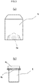
- the joined member 5 has a flat plate part 5b having a predetermined thickness and configured to cover the step part 4b and protruding part 4c of the joining member 4. As shown in FIGS. 3(a) and 3(b) , the joined member has a hole portion 5a in which the step part 4b and protruding part 4c of the joining member 4 can be fitted, before forming the joined member. As shown in FIGS.
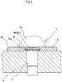
- the negative-side external terminal 3 has a non-penetration joining structure S for enabling non-detachably joining both the members by placing the joined member 5 over the joining member 4 so that the step part 4b and protruding part 4c of the joining member 4 are positioned in the blind hole 5a of the joined member 5 and compressing the joined member 5 against a receiving mold 6 (which will be described later) to plastically deform the joined member 5 and the joining member 4 at the same time and to wrap excess thickness of the joined member 5 around an undercut part 4cc while forming the undercut part 4cc on the joining member 4.
- a receiving mold 6 which will be described later
- the undercut part 4cc of the joining member 4 forms a groove around which the excess thickness of the joined member 5 is wrapped, so that the joined member 5 is prevented from being separated. Also, the excess thickness of the joined member 5 is caulked by a backside of the undercut part 4cc of the joining member 4, so that adhesiveness between the joining member and the joined member is improved and high axial strength is thus obtained. Also, the excess thickness of the joined member 5 is wrapped around and into tooth-shaped gaps of the step part 4b, so that a resistance in a rotating direction increases and high strength in the rotating direction is obtained. In addition, since the joined portion is in a non-penetration state in the hole portion 5a, the joining structure having high airtightness is obtained.
- the negative-side external terminal 3 is used at a part that is to communicate with a closed inside such as the battery can 1b of a lithium battery 1 having liquid filled therein, the liquid is not leaked.
- the flat plate part 5b capable of sufficiently securing a space for welding a lead wire and the like and securing a corrosion resistance thereof.
- the joined member 5 is softer than the joining member 4, the fluidity of the joined member 5 is better, so that it is possible to further improve the adhesiveness.
- the joining member 4 and the joined member 5 are made of the same material, the similar effects are obtained although a degree of improvement on the adhesiveness is different.
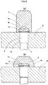
- the negative-side external terminal 3 is manufactured by the first joining method shown in FIGS. 1 , 3 and 4 . That is, the first joining method includes a manufacturing process (not shown) of the joining member 4 and a manufacturing process (not shown) of the joined member 5. Also, the first joining method includes a fitting process of placing the joined member 5 over the joining member 4 so that the step part 4b and protruding part 4c of the joining member 4 are fitted to the hole portion 5a of the joined member 5, as shown in FIG. 4(a) , a preforming process of compressing the joined member 5 to form a preformed part 5c having a preliminary shape before finish forming, as shown in FIG.
- the fitting process includes positionally determining the shaft part 4a of the joining member 4 in the receiving mold 6 by a knockout pin 7, placing the joined member 5 over the joining member 4 from the upper so that the step part 4b and protruding part 4c of the joining member 4 are positioned in the blind hole 5a of the joined member 5, and fitting the members (refer to FIG. 4(a) ).
- an advancing direction of the joined member 5 is not limited to "from the upper", and may be "from a horizontal direction" when the joining member 4 and the joined member 5 are arranged in the horizontal direction.
- the preforming process of the joined member 5 includes a preforming pressing mold (not shown) configured to form the joined member 5, which is to be fitted to the step part 4b and protruding part 4c of the joining member 4, into the preformed part 5c having a preliminary shape before finish forming.
- the preforming pressing mold is configured to advance relative to the receiving mold 6 and to compress an upper part of the joined member 5, thereby forming the preformed part 5c corresponding to a forming hole formed in the preforming pressing mold, i.e., a preliminary shape.
- the excess thickness of the joined member 5 is wrapped around and into gaps between the step part 4b and protruding part 4c of the joining member 4 and an inner wall of the hole portion 5a of the joined member 5, so that the members are joined with the shaft part 4a of the joining member 4 being kept by the receiving mold 6.
- the preforming process is not a process that is to be necessarily performed in the first joining method. That is, when the joined member 5 is made of a material having favorable ductility, the joined member 5 may be directly formed through the forming process from the fitting process.
- the forming process includes a forming pressing mold (not shown) configured to form the flat plate part 5b having a predetermined thickness from the preformed part 5c of the joined member 5.
- the forming pressing mold is configured to advance relative to the preformed part 5c from the upper and to form the preformed part 5c into the flat plate part 5b having a predetermined thickness or having a predetermined thickness and a predetermined shape.
- a bottom dead point of the forming pressing mold is determined so that the protruding part 4c of the joining member 4 is not exposed, taking into consideration a thickness of the flat plate part 5b, the ductility of the joined member 5, a fitting depth between the protruding part 4c of the joining member 4 and the hole portion 5a of the joined member 5, hardness of the joining member 4, and the like.
- the shaft part 4a of the joining member 4 is positionally determined in the receiving mold 6 by the knockout pin 7 and the step part 4b is kept on an upper surface of the receiving mold 6 at the same time.
- the preforming pressing mold is advanced relative to the receiving mold 6 and compresses an upper part of the joined member 5 to form the preformed part 5c, as shown in FIG. 4(b) .
- the preforming pressing mold plastically deforms the protruding part 4c of the joining member 4 via the joined member 5 softer than the joining member 4, flattens slightly outward an outer periphery of an upper end of the protruding part, and wraps the excess thickness of the joined member 5 around the undercut part 4cc while forming the undercut part 4cc on the joining member 4.
- the forming pressing mold After retreating the preforming pressing mold, the forming pressing mold is advanced to a predetermined bottom dead point, relative to the receiving mold 6, as shown in FIG. 1 .
- the forming pressing mold compresses the preformed part 5c to form the flat plate part 5b having a predetermined thickness.
- the preformed part 5c i.e., the joined member 5 is formed so that the protruding part of the joining member 4c is not exposed, and at the same time, the joining member 4 and the joined member 5 are non-detachably joined.
- the members are joined in a state of non-penetration, i.e., in a state in which airtightness is maintained at the joined portion.
- the excess thickness of the preformed part 5c i.e., the joined member 5 is wrapped around and into the gaps of the step part 4b having the tooth-shaped outer periphery, so that a large circular cylinder step part 4b1 is formed below a neck of the flat plate part 5b and a resistance in the rotating direction thus increases.
- a friction resistance at the periphery of the outer side of the step part 4b of the joining member 4 but also the resistance in the rotating direction increases as a result of the wrapping of the excess thickness of the preformed part 5c around and into the gaps of the tooth-shaped step part, so that the strength in the rotating direction is improved.
- the forming pressing mold plastically deforms the protruding part 4c of the joining member 4 via the preformed part 5c, so that the outer periphery of the upper end of the protruding part is further flattened outward and the undercut part 4cc is formed.
- the undercut part 4cc of the joining member 4 caulks the excess thickness of the preformed part 5c at a backside of the undercut part, and the excess thickness can be wrapped around and into the gap between the step part 4b of the joining member 4 and the preformed part 5c.
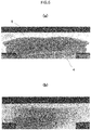
- the gaps are not recognized at the joined portion in accordance with the first joining method, the excess thickness is sufficiently wrapped and the high adhesiveness is thus obtained between the joining member 4 and the joined member 5.
- the aluminum member of A1070 is used for the joined member 5 and the copper member is used for the joining member 4, so that the joined member 5 is made of a material softer than the joining member 4.
- the joining member 4 is formed with the groove part 104a of the related art in advance.
- the backside of the undercut part 4cc of the joining member 4 caulks the excess thickness of the preformed part 5c between the step part 4b of the joining member 4 and the upper surface of the receiving mold 6, thereby pushing the excess thickness into the gap between the step part 4b and protruding part 4c of the joining member 4 and the preformed part 5c while work-hardening the excess thickness.
- the joining member 4 having a simple structure can be used, and the work-hardening of the excess thickness and the axial strength of the joining member 4, i.e., the strength in the separation direction can be increased.
- the forming pressing mold is configured to advance to the predetermined bottom dead point to form the flat plate part 5b having a predetermined thickness from the preformed part 5c of the joined member 5.
- the bottom dead point is determined so that the protruding part 4c of the joining member 4 is not exposed, taking into consideration the ductility of the joined member 5, the fitting depth between the protruding part 4c of the joining member 4 and the hole portion 5a of the joined member 5, and the like.
- the joining member 4 and the joined member 5 are joined in the state of non-penetration, i.e., in the state in which airtightness is maintained at the joined portion, without the protruding part 4c of the joining member 4 being exposed, so that the negative-side external terminal 3 having high airtightness can be manufactured. Also, since it is possible to omit the process of forming the joined member 5 in advance, it is possible to manufacture the inexpensive negative-side external terminal 3.
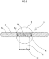
- FIG. 8 depicts non-penetration joining structures S1, S2 in accordance with a first modified embodiment (a) and a second modified embodiment (b) of the first joining method of the present invention.
- the non-penetration joining structure S1 is a structure obtained by forming the joined member 5 with the step part 4b of the joining member 4 being kept in the receiving mold (not shown).
- the non-penetration joining structure S1 is a structure for enabling non-detachably joining both the members by compressing the joined member 5 against the receiving mold to plastically deform the joined member 5 and the joining member 4 at the same time and to wrap the excess thickness of the joined member 5 around the undercut part 4cc while forming the undercut part 4cc on the joining member 4.
- the excess thickness of the joined member 5 is wrapped around and into the gaps of the step part 4b having the tooth-shaped outer periphery, so that the large circular cylinder step part 4b1 is formed below the neck of the flat plate part 5b.
- non-penetration joining structure S2 a member having a small circular cylinder step part 4b2 between the step part 4b and the protruding part 4c is used as the joining member 4.
- the non-penetration joining structure S2 has the same structure as the first modified embodiment, except the small circular cylinder step part 4b2.
- any of the non-penetration joining structures S1, S2 has the large circular cylinder step part 4b1 below the neck, not only the friction resistance at the periphery of the outer side of the step part 4b of the joining member 4 but also the resistance in the rotating direction increases as a result of the wrapping of the excess thickness of the preformed part 5c around the outer periphery of the tooth-shaped step part, so that the negative-side external terminals 3a, 3b having the high strength in the rotating direction can be obtained.
- FIGS. 9(a) and 9(b) depict a joining method of members in accordance with a modified embodiment of the first joining method of the present invention.
- a member having the shaft part 4a and a joining protruding part 4c1 having a diameter larger than the shaft part and a non-circular hole 4c2 formed in an upper surface thereof is used as the joining member 4.
- the joining method includes a fitting process of placing the joined member 5 over the joining member 4 so that the hole portion 5a of the joined member 5 is fitted to the joining protruding part 4c1 of the joining member 4, and a forming process of the joined member 5.
- the shaft part 4a is positionally determined by the receiving mold 6 and the knockout pin 7 with the joining protruding part 4c1 of the joining member 4 being in contact with the upper surface of the receiving mold 6.
- the joined member 5 is advanced relative to the joining member 4 in the receiving mold 6, and the joined member 5 is placed over the joining member 4 from the upper so that the protruding part 4c of the joining member 4 is positioned in the blind hole 5a of the joined member 5.
- the joined member 5 is partially fitted to the joining member 4 and is thus kept to the joining member 4.
- the forming pressing mold (not shown) is arranged, and as shown in FIG. 9(b) , the forming pressing mold is advanced to a predetermined bottom dead point, relative to the joining member 4 positionally determined in the receiving mold 6 and the joined member 5 fitted to the joining member from the upper of the members.
- the bottom dead point of the forming pressing mold is set so that the joined member 5 is compressed to form the flat plate part 5b having a predetermined thickness and the joining protruding part 4c1 is not exposed, like the bottom dead point of the first joining method.
- the forming pressing mold compresses the joined member 5 to form the flat plate part 5b having a predetermined thickness.
- the joining protruding part 4c1 of the joining member 4 is plastically deformed via the joined member 5, so that an outer periphery of an upper end of the joining protruding part is flattened outward and the undercut part 4cc is formed.
- the joining protruding part 4c1 of the joining member 4 is formed, the joining member 4 and the joined member 5 are non-detachably joined in the state of non-penetration, i.e., in the state in which airtightness is maintained at the joined portion.
- the forming pressing mold plastically deforms the joining protruding part 4c1 via the joined member 5.
- the joining protruding part 4c1 has the non-circular hole 4c2
- the joining protruding part is likely to be flattened outward over an entire circumference thereof, so that the undercut part 4cc can be easily formed. Thereby, it is possible to improve the strength in the axial direction, i.e., in the separation direction.
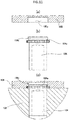
- the second joining method includes a fitting process of the joining member 4 and the joined member 5, a preforming process of the joined member 5 and a forming process of the joined member 5.
- the fitting process is similar to the first joining method, as shown in FIG.
- the protruding part 4c more protrudes upward than the upper surface of the receiving mold 6, and has threads 4e formed on the outer periphery thereof.
- the thread 4e is formed with a vertical groove 4f extending in the axial direction.
- the thread 4e may not be formed with the vertical groove 4f. In this case, the strength in the rotating direction is slightly lowered but the separation strength is not lowered.
- a preforming pressing mold (not shown) configured to compress an upper part of the joined member 5 is arranged.
- the preforming pressing mold is configured to advance relative to the joined member 5, and to compress the upper part of the joined member 5 within a range in which the protruding part 4c of the joining member 4 is not plastically deformed, thereby forming the preformed part 5c corresponding to a preliminary shape formed in the preforming pressing mold, as shown in FIG. 10(b) .
- the excess thickness of the joined member 5 is wrapped around and into the gap between the protruding part 4c of the joining member 4 and the joined member 5, between the two adjacent threads 4e, 4e, and the vertical grooves 4f.
- a forming pressing mold (not shown) is arranged.
- the forming pressing mold is configured to advance to a predetermined bottom dead point, and to compress the preformed part 5c to form the flat plate part 5b having a predetermined thickness.
- the forming pressing mold is configured to plastically deform a protruding end of the protruding part 4c of the joining member 4 and to flatten the same outward, thereby forming the undercut part 4cc.
- the present invention includes keeping the metallic joining member 4 having the protruding part 4c by the receiving mold 6 so that the protruding part 4c is exposed, placing the joined member 5 over the joining member 4 so that the protruding part 4c of the joining member 4 is positioned in the blind hole 5a of the joined member 5, and compressing the joined member 5 against the receiving mold 6 to plastically deform the joined member 5 and the joining member 4 at the same time and to wrap the excess thickness of the joined member 5 around the undercut part 4cc while forming the undercut part 4cc on the joining member 4, thereby non-detachably joining both the members.
- the joining member 4 and the joined member 5 By this configuration, it is possible to join the joining member 4 and the joined member 5 while forming the joined member 54 so that the protruding part 4c of the joining member is not exposed.
- a composite component can be manufactured in which the joining member 4 and the joined member 5 are joined in the state of non-penetration, i.e., in the state in which airtightness is maintained at the joined portion. Also, it is not necessary to form the joined member 5 in advance, so that it is possible to save the manufacturing cost of the composite component.
- the undercut part 4cc of the joining member 4 forms a groove around which the excess thickness of the joined member 5 is to be wrapped, so that it is possible to non-detachably join both the members without performing extra processing such as groove processing in advance. Also, the excess thickness of the joined member 5 is caulked by the backside of the undercut part 4cc, so that the adhesiveness between the joining member 4 and the joined member 5 is improved and the high axial strength can be thus obtained.
- the joined member 5 and the joining member 4 are preferably closely contacted at the undercut part 4cc.
- the excess thickness of the joined member 5 is caulked by the backside of the undercut part 4cc, so that it is possible to improve the adhesiveness between the joining member 4 and the joined member 5.
- the joined member 5 may be made of a material softer than the joining member 4, and the joining member 4 may be caused to be deformed using the work-hardening of the joined member 4.
- the fluidity of the joined member 5 is made better to improve the adhesiveness between the joining member 4 and the joined member 5.
- the protruding part 4c of the joining member 4 of the present invention has the step part 4b widely enlarged in the vicinity of the protruding end, the undercut part 4cc is formed at a position closer to the protruding end than the step part 4b, and the excess thickness of the joined member 5 is wrapped around the outer side of the step part 4b, as well, so that the joining member 4 and the joined member 5 are joined.
- the outer periphery of the step part 4b of the joining member 4 of the present invention has a tooth shape.
- the present invention provides the non-penetration joining structure including the metallic joining member 4 having the protruding part 4c, the joined member 5 having the blind hole 5a in which the protruding part 4c of the joining member 4 can be inserted, and the undercut part 4cc plastically processed at the protruding part 4c of the joining member 4 by compressing the joined member 5 with the protruding part 4c of the joining member 4 being inserted in the blind hole 5a of the joined member 5 and configured to non-detachably join both the members by wrapping the excess thickness of the fastened member 5 around the undercut part.
- the undercut part 4cc of the joining member 4 forms a groove around which the excess thickness of the joined member 5 is wrapped, so that the joined member 5 is prevented from being separated. Also, the excess thickness of the joined member 5 is caulked by the backside of the undercut part 4cc of the joining member 4, so that the adhesiveness between the members is improved and the high axial strength is thus obtained. Also, since the joined portion is in a non-penetration state in the hole portion 5a, the joining structure having high airtightness is obtained.
- the undercut part 4cc of the present invention is configured to closely contact the joined member 5 and the joining member 4.
- the joined member 5 of the present invention is made of a material softer than the joining member 4, and the joining member 4 is caused to be deformed using the work-hardening of the joined member 5.
- the protruding part 4c of the present invention has the step part 4b widely enlarged in the vicinity of the protruding end, the undercut part 4cc is formed at a position closer to the protruding end than the step part 4b, and the excess thickness is wrapped around the outer side of the step part 4b, as well, so that the joining member 4 and the joined member 5 are joined.
- the outer periphery of the step part 4b has a tooth shape.
- the horizontal arrangement of the receiving mold 6 and the joined member 5 made of a material softer than the joining member 4 can be applied.
- the joining member 4 and the joined member 5 are not limited to the metal materials, and may be made of resin materials.
Landscapes
- Engineering & Computer Science (AREA)
- Mechanical Engineering (AREA)
- General Engineering & Computer Science (AREA)
- Manufacturing & Machinery (AREA)
- General Chemical & Material Sciences (AREA)
- Electrochemistry (AREA)
- Chemical Kinetics & Catalysis (AREA)
- Chemical & Material Sciences (AREA)
- Pressure Welding/Diffusion-Bonding (AREA)
- Connection Of Batteries Or Terminals (AREA)
- Connection Of Plates (AREA)
- Insertion Pins And Rivets (AREA)
- Measuring Fluid Pressure (AREA)
Claims (8)
- Fügeverfahren mit einem nicht durch ein gefügtes Element (5) hindurch dringenden Fügeelement (4) für eine Lithiumbatterie, wobei das Verfahren umfasst:Halten eines Fügeelements (4), das einen vorragenden Teil (4c) aufweist, durch eine Aufnahmeform (6) derart, dass der vorragende Teil (4c) exponiert ist;Platzieren eines gefügten Elements (5) über dem Fügeelement (4) derart, dass der vorragende Teil (4c) des Fügeelements (4) in einem Sackloch (5a) des gefügten Elements (5) positioniert ist, undKomprimieren des gefügten Elements (5) gegen die Aufnahmeform (6), um das gefügte Element (5) und das Fügeelement (4) gleichzeitig plastisch zu verformen, und um eine Überdicke des gefügten Elements (5) um einen hinterschnittenen Teil (4cc) zu legen, während der hinterschnittene Teil (4cc) an dem Fügeelement (4) gebildet wird, wodurch beide Elemente (4, 5) unlösbar gefügt werden,wobei das gefügte Element (5) aus einem Material hergestellt ist, das weicher ist als das Fügeelement (4), und das Fügeelement (4) durch Kaltverfestigung des gefügten Elements (5) veranlasst wird, sich zu verformen.
- Fügeverfahren mit einem nicht durch ein gefügtes Element (5) hindurch dringendes Fügeelement (4) nach Anspruch 1, wobei das gefügte Element (5) und das Fügeelement (4) einander an dem hinterschnittenen Teil (4cc) eng berühren.
- Fügeverfahren mit einem nicht durch ein gefügtes Element (5) hindurch dringendes Fügeelements (4) nach Anspruch 1 oder 2, wobei der vorragende Teil (4c) einen Stufenteil (4b) aufweist, der in der Nähe eines vorragenden Endes stark erweitert ist, wobei der hinterschnittene Teil (4cc) an einer Position näher an dem vorragenden Ende als der Stufenteil (4b) gebildet ist, und die Überdicke auch um eine Außenseite des Stufenteils (4b) gelegt wird, so dass das Fügeelement (4) und das gefügte Element (5) gefügt werden.
- Fügeverfahren mit einem nicht durch ein gefügtes Element (5) hindurch dringendes Fügeelement (4) nach Anspruch 3, wobei ein Außenumfang des Stufenteils (4b) eine Zahnform aufweist.
- Fügestruktur ohne Eindringen für eine Lithiumbatterie mit einem nicht durch ein gefügtes Element (5) hindurch dringenden Fügeelement (4), die umfasst:ein Fügeelement (4), das einen vorragenden Teil (4c) umfasst;ein gefügtes Element (5), das ein Sackloch (5a) aufweist, in das der vorragende Teil (4c) des Fügeelements (4) eingefügt ist, undeinen hinterschnittenen Teil (4cc), der plastisch an dem vorragenden Teil (4c) des Fügeelements (4) durch Komprimieren des grefügten Elements (5) mit dem vorragenden Teil (4c) des Fügeelements (4), das in das Sackloch (5a) des gefügten Elements (5) eingefügt ist, verarbeitet ist, und dazu konfiguriert ist, beide Elemente (4, 5) unlösbar zu fügen, indem Überdicke des befestigten Elements um den hinterschnittenen Teil (4cc) gelegt ist,wobei das gefügte Element (5) aus einem Material hergestellt ist, das weicher ist als das Fügeelement (4), und das Fügeelement (4) veranlasst ist, sich unter Verwenden von Kaltverfestigung des gefügten Elements (5) zu verformen.
- Fügestruktur ohne Eindringen für eine Lithiumbatterie mit einem nicht durch ein gefügtes Element (5) hindurch dringenden Fügeelement (4) nach Anspruch 5, wobei das gefügte Element (5) und das Fügeelement (4) einander an dem hinterschnittenen Teil (4cc) eng berühren.
- Fügestruktur ohne Eindringen für eine Lithiumbatterie mit einem nicht durch ein gefügtes Element (5) hindurch dringenden Fügeelement (4) nach Anspruch 5 oder 6, wobei der vorragende Teil (4c) einen Stufenteil (4b) aufweist, der in der Nähe eines vorragenden Endes stark erweitert ist, wobei der hinterschnittene Teil (4cc) an einer Position näher an dem vorragenden Ende als der Stufenteil (4b) gebildet ist, und die Überdicke auch um eine Außenseite des Stufenteils (4b) gelegt ist, so dass das Fügeelement (4) und das gefügte Element (5) gefügt sind.
- Fügestruktur ohne Eindringen für eine Lithiumbatterie mit einem nicht durch ein gefügtes Element (5) hindurch dringenden Fügeelement (4) nach Anspruch 7, wobei ein Außenumfang des Stufenteils (4b) eine Zahnform aufweist.
Applications Claiming Priority (3)
| Application Number | Priority Date | Filing Date | Title |
|---|---|---|---|
| JP2016127932A JP6430442B2 (ja) | 2016-06-28 | 2016-06-28 | 金属部材の非貫通接合方法 |
| JP2016130421A JP6383385B2 (ja) | 2016-06-30 | 2016-06-30 | 金属部材の接合方法および金属製の複合部材の製造方法 |
| PCT/JP2017/007940 WO2018003175A1 (ja) | 2016-06-28 | 2017-02-28 | 部材の非貫通接合方法および非貫通接合構造 |
Publications (3)
| Publication Number | Publication Date |
|---|---|
| EP3476501A1 EP3476501A1 (de) | 2019-05-01 |
| EP3476501A4 EP3476501A4 (de) | 2020-01-29 |
| EP3476501B1 true EP3476501B1 (de) | 2021-09-22 |
Family
ID=60786812
Family Applications (1)
| Application Number | Title | Priority Date | Filing Date |
|---|---|---|---|
| EP17819545.9A Active EP3476501B1 (de) | 2016-06-28 | 2017-02-28 | Verfahren zur nichtpenetrierenden verbinden von elementen und nichtpenetrierende verbindungsstruktur |
Country Status (10)
| Country | Link |
|---|---|
| US (1) | US11207802B2 (de) |
| EP (1) | EP3476501B1 (de) |
| KR (1) | KR102498574B1 (de) |
| CN (1) | CN108698109B (de) |
| AU (1) | AU2017287028B2 (de) |
| BR (1) | BR112018017113B1 (de) |
| MX (1) | MX2018015907A (de) |
| MY (1) | MY192502A (de) |
| TW (1) | TWI737752B (de) |
| WO (1) | WO2018003175A1 (de) |
Families Citing this family (3)
| Publication number | Priority date | Publication date | Assignee | Title |
|---|---|---|---|---|
| JP7214693B2 (ja) | 2020-09-17 | 2023-01-30 | プライムプラネットエナジー&ソリューションズ株式会社 | 端子及びそれを備えた二次電池並びにそれらの製造方法 |
| JP7214692B2 (ja) | 2020-09-17 | 2023-01-30 | プライムプラネットエナジー&ソリューションズ株式会社 | 端子及びそれを備えた二次電池並びにそれらの製造方法 |
| JP7285865B2 (ja) * | 2021-01-21 | 2023-06-02 | プライムプラネットエナジー&ソリューションズ株式会社 | 端子部品、二次電池および端子部品の製造方法 |
Family Cites Families (19)
| Publication number | Priority date | Publication date | Assignee | Title |
|---|---|---|---|---|
| JPS6229146Y2 (de) | 1979-12-14 | 1987-07-27 | ||
| JPS60181220U (ja) | 1985-04-03 | 1985-12-02 | 株式会社日立製作所 | プレス加工用ポンチ |
| JPH0631332U (ja) | 1992-09-30 | 1994-04-22 | 日新電機株式会社 | 模擬母線 |
| JP3552154B2 (ja) | 1998-01-12 | 2004-08-11 | 古河スカイ株式会社 | アルミニウム又はアルミニウム合金部材からなる密封体、並びに半導体製造装置又は薄型ディスプレー製造装置の基板ホルダー及びそれを製造する方法 |
| US6376815B1 (en) | 1998-01-12 | 2002-04-23 | Furukawa Electric Co., Ltd. | Highly gas tight substrate holder and method of manufacturing the same |
| CA2256987C (en) * | 1998-12-23 | 2003-01-07 | Peter Ling | Terminal seal for electrolytic devices |
| JP3868361B2 (ja) | 2002-10-04 | 2007-01-17 | 株式会社日立製作所 | 塑性流動結合体とその結合方法 |
| JP4024143B2 (ja) | 2002-12-25 | 2007-12-19 | 松下電器産業株式会社 | 流体軸受部材の製造方法 |
| JP4127532B2 (ja) | 2003-09-25 | 2008-07-30 | 株式会社青山製作所茨城工場 | 異材質部材からなる二部材の密封結合構造、及びその結合方法 |
| WO2007139048A1 (ja) | 2006-05-30 | 2007-12-06 | Bosch Corporation | スタッドボルト、スタッドボルト取付構造及びこれを用いた倍力装置 |
| JP5197990B2 (ja) | 2007-04-26 | 2013-05-15 | ボッシュ株式会社 | スタッドボルト取付構造及びこれを用いた倍力装置 |
| TWI343677B (en) * | 2007-10-11 | 2011-06-11 | Ks Terminals Inc | Terminal connector with easy entry and manufacturing method thereof |
| KR101196561B1 (ko) | 2007-12-21 | 2012-11-01 | 니폰게이긴조쿠가부시키가이샤 | 접합 방법 |
| JP6024095B2 (ja) | 2010-12-10 | 2016-11-09 | 株式会社Gsユアサ | 蓄電素子、蓄電素子の製造方法、及び、端子の製造方法 |
| JP5609610B2 (ja) | 2010-12-10 | 2014-10-22 | 株式会社Gsユアサ | 電池 |
| JP2012226836A (ja) * | 2011-04-14 | 2012-11-15 | Toyota Motor Corp | 電池の製造方法 |
| JP5201643B2 (ja) | 2011-07-22 | 2013-06-05 | 株式会社テクノクラーツ | アンダーカット処理機構 |
| JP5639558B2 (ja) | 2011-09-29 | 2014-12-10 | 株式会社テクノアソシエ | 金属板と金属軸の結合構造及び密閉型電池の電極構造 |
| US20140295252A1 (en) * | 2013-03-26 | 2014-10-02 | Hitachi Metals, Ltd. | Electrode terminal connection body and manufacturing method of the same |
-
2017
- 2017-02-28 MX MX2018015907A patent/MX2018015907A/es unknown
- 2017-02-28 US US16/080,992 patent/US11207802B2/en active Active
- 2017-02-28 MY MYPI2018703477A patent/MY192502A/en unknown
- 2017-02-28 WO PCT/JP2017/007940 patent/WO2018003175A1/ja not_active Ceased
- 2017-02-28 BR BR112018017113-1A patent/BR112018017113B1/pt active IP Right Grant
- 2017-02-28 KR KR1020187032378A patent/KR102498574B1/ko active Active
- 2017-02-28 EP EP17819545.9A patent/EP3476501B1/de active Active
- 2017-02-28 CN CN201780014002.8A patent/CN108698109B/zh active Active
- 2017-02-28 AU AU2017287028A patent/AU2017287028B2/en active Active
- 2017-06-22 TW TW106120824A patent/TWI737752B/zh active
Also Published As
| Publication number | Publication date |
|---|---|
| MY192502A (en) | 2022-08-24 |
| CN108698109A (zh) | 2018-10-23 |
| BR112018017113B1 (pt) | 2022-04-19 |
| CN108698109B (zh) | 2024-07-26 |
| AU2017287028A1 (en) | 2018-08-23 |
| EP3476501A1 (de) | 2019-05-01 |
| BR112018017113A2 (pt) | 2019-01-15 |
| EP3476501A4 (de) | 2020-01-29 |
| KR102498574B1 (ko) | 2023-02-09 |
| TWI737752B (zh) | 2021-09-01 |
| US20200108527A1 (en) | 2020-04-09 |
| US11207802B2 (en) | 2021-12-28 |
| WO2018003175A1 (ja) | 2018-01-04 |
| AU2017287028B2 (en) | 2022-03-10 |
| TW201813157A (zh) | 2018-04-01 |
| MX2018015907A (es) | 2019-03-28 |
| KR20190022473A (ko) | 2019-03-06 |
Similar Documents
| Publication | Publication Date | Title |
|---|---|---|
| KR101569596B1 (ko) | 전선과 단자의 접속구조 및 그 제조방법 | |
| CN102610783B (zh) | 蓄电元件及其制造方法 | |
| US8876564B2 (en) | Connection structure of crimping terminal to electric wire | |
| EP3185267B1 (de) | Kondensator und herstellungsverfahren dafür | |
| US9502784B2 (en) | Terminal attached aluminum electric wire | |
| US11207802B2 (en) | Method for non-penetration joining of members and non-penetration joining structure | |
| JP5447071B2 (ja) | 端子金具付き電線及びその製造方法 | |
| JP2013114799A (ja) | 密閉型電池 | |
| JP6803877B2 (ja) | 端子付き電線 | |
| JP6613346B2 (ja) | 金属部材の非貫通接合構造 | |
| JP2018001209A (ja) | 金属部材の接合方法および接合構造 | |
| JP2012134300A (ja) | 半導体装置 | |
| JP6430442B2 (ja) | 金属部材の非貫通接合方法 | |
| CN104126252B (zh) | 电线连接结构体、电线连接结构体的制造方法、具备电线连接结构体的连接器、以及压接用模 | |
| JP2019195851A (ja) | 金属部材の接合方法 | |
| JP2014164946A (ja) | 端末絶縁剥離電線、及び、電線接続構造体 | |
| KR20220106055A (ko) | 단자 부품, 이차 전지 및 단자 부품의 제조 방법 | |
| JP7594453B2 (ja) | 異種金属部品接合方法 | |
| JP2016046140A (ja) | 端子付き電線の製造方法 | |
| US20180331485A1 (en) | Method of manufacturing terminal-equipped conductive member, conductive member, and terminal-equipped wire | |
| JP2015095313A (ja) | 絶縁電線、および、絶縁電線の製造方法 | |
| JP2022104017A (ja) | 異種金属部品接合方法 | |
| JP2017103127A (ja) | 端子、蓄電池及び端子の製造方法 | |
| JP2014186993A (ja) | ワイヤハーネス、および、ワイヤハーネスの製造方法 | |
| JP2021005492A (ja) | 端子付き電線、及び、端子付き電線の製造装置 |
Legal Events
| Date | Code | Title | Description |
|---|---|---|---|
| STAA | Information on the status of an ep patent application or granted ep patent |
Free format text: STATUS: THE INTERNATIONAL PUBLICATION HAS BEEN MADE |
|
| PUAI | Public reference made under article 153(3) epc to a published international application that has entered the european phase |
Free format text: ORIGINAL CODE: 0009012 |
|
| STAA | Information on the status of an ep patent application or granted ep patent |
Free format text: STATUS: REQUEST FOR EXAMINATION WAS MADE |
|
| 17P | Request for examination filed |
Effective date: 20181031 |
|
| AK | Designated contracting states |
Kind code of ref document: A1 Designated state(s): AL AT BE BG CH CY CZ DE DK EE ES FI FR GB GR HR HU IE IS IT LI LT LU LV MC MK MT NL NO PL PT RO RS SE SI SK SM TR |
|
| AX | Request for extension of the european patent |
Extension state: BA ME |
|
| DAV | Request for validation of the european patent (deleted) | ||
| DAX | Request for extension of the european patent (deleted) | ||
| A4 | Supplementary search report drawn up and despatched |
Effective date: 20200108 |
|
| RIC1 | Information provided on ipc code assigned before grant |
Ipc: B21D 39/00 20060101AFI20191220BHEP Ipc: H01M 2/06 20060101ALI20191220BHEP |
|
| STAA | Information on the status of an ep patent application or granted ep patent |
Free format text: STATUS: EXAMINATION IS IN PROGRESS |
|
| 17Q | First examination report despatched |
Effective date: 20201111 |
|
| GRAP | Despatch of communication of intention to grant a patent |
Free format text: ORIGINAL CODE: EPIDOSNIGR1 |
|
| STAA | Information on the status of an ep patent application or granted ep patent |
Free format text: STATUS: GRANT OF PATENT IS INTENDED |
|
| RIC1 | Information provided on ipc code assigned before grant |
Ipc: H01M 50/172 20210101ALN20210316BHEP Ipc: B21D 39/00 20060101AFI20210316BHEP |
|
| INTG | Intention to grant announced |
Effective date: 20210415 |
|
| GRAS | Grant fee paid |
Free format text: ORIGINAL CODE: EPIDOSNIGR3 |
|
| GRAA | (expected) grant |
Free format text: ORIGINAL CODE: 0009210 |
|
| STAA | Information on the status of an ep patent application or granted ep patent |
Free format text: STATUS: THE PATENT HAS BEEN GRANTED |
|
| AK | Designated contracting states |
Kind code of ref document: B1 Designated state(s): AL AT BE BG CH CY CZ DE DK EE ES FI FR GB GR HR HU IE IS IT LI LT LU LV MC MK MT NL NO PL PT RO RS SE SI SK SM TR |
|
| REG | Reference to a national code |
Ref country code: GB Ref legal event code: FG4D |
|
| REG | Reference to a national code |
Ref country code: IE Ref legal event code: FG4D |
|
| REG | Reference to a national code |
Ref country code: DE Ref legal event code: R096 Ref document number: 602017046479 Country of ref document: DE |
|
| REG | Reference to a national code |
Ref country code: CH Ref legal event code: EP Ref country code: AT Ref legal event code: REF Ref document number: 1431909 Country of ref document: AT Kind code of ref document: T Effective date: 20211015 |
|
| REG | Reference to a national code |
Ref country code: SE Ref legal event code: TRGR |
|
| REG | Reference to a national code |
Ref country code: LT Ref legal event code: MG9D |
|
| REG | Reference to a national code |
Ref country code: NL Ref legal event code: MP Effective date: 20210922 |
|
| PG25 | Lapsed in a contracting state [announced via postgrant information from national office to epo] |
Ref country code: NO Free format text: LAPSE BECAUSE OF FAILURE TO SUBMIT A TRANSLATION OF THE DESCRIPTION OR TO PAY THE FEE WITHIN THE PRESCRIBED TIME-LIMIT Effective date: 20211222 Ref country code: LT Free format text: LAPSE BECAUSE OF FAILURE TO SUBMIT A TRANSLATION OF THE DESCRIPTION OR TO PAY THE FEE WITHIN THE PRESCRIBED TIME-LIMIT Effective date: 20210922 Ref country code: BG Free format text: LAPSE BECAUSE OF FAILURE TO SUBMIT A TRANSLATION OF THE DESCRIPTION OR TO PAY THE FEE WITHIN THE PRESCRIBED TIME-LIMIT Effective date: 20211222 Ref country code: RS Free format text: LAPSE BECAUSE OF FAILURE TO SUBMIT A TRANSLATION OF THE DESCRIPTION OR TO PAY THE FEE WITHIN THE PRESCRIBED TIME-LIMIT Effective date: 20210922 Ref country code: FI Free format text: LAPSE BECAUSE OF FAILURE TO SUBMIT A TRANSLATION OF THE DESCRIPTION OR TO PAY THE FEE WITHIN THE PRESCRIBED TIME-LIMIT Effective date: 20210922 Ref country code: HR Free format text: LAPSE BECAUSE OF FAILURE TO SUBMIT A TRANSLATION OF THE DESCRIPTION OR TO PAY THE FEE WITHIN THE PRESCRIBED TIME-LIMIT Effective date: 20210922 |
|
| REG | Reference to a national code |
Ref country code: AT Ref legal event code: MK05 Ref document number: 1431909 Country of ref document: AT Kind code of ref document: T Effective date: 20210922 |
|
| PG25 | Lapsed in a contracting state [announced via postgrant information from national office to epo] |
Ref country code: LV Free format text: LAPSE BECAUSE OF FAILURE TO SUBMIT A TRANSLATION OF THE DESCRIPTION OR TO PAY THE FEE WITHIN THE PRESCRIBED TIME-LIMIT Effective date: 20210922 Ref country code: GR Free format text: LAPSE BECAUSE OF FAILURE TO SUBMIT A TRANSLATION OF THE DESCRIPTION OR TO PAY THE FEE WITHIN THE PRESCRIBED TIME-LIMIT Effective date: 20211223 |
|
| PG25 | Lapsed in a contracting state [announced via postgrant information from national office to epo] |
Ref country code: AT Free format text: LAPSE BECAUSE OF FAILURE TO SUBMIT A TRANSLATION OF THE DESCRIPTION OR TO PAY THE FEE WITHIN THE PRESCRIBED TIME-LIMIT Effective date: 20210922 |
|
| PG25 | Lapsed in a contracting state [announced via postgrant information from national office to epo] |
Ref country code: IS Free format text: LAPSE BECAUSE OF FAILURE TO SUBMIT A TRANSLATION OF THE DESCRIPTION OR TO PAY THE FEE WITHIN THE PRESCRIBED TIME-LIMIT Effective date: 20220122 Ref country code: SK Free format text: LAPSE BECAUSE OF FAILURE TO SUBMIT A TRANSLATION OF THE DESCRIPTION OR TO PAY THE FEE WITHIN THE PRESCRIBED TIME-LIMIT Effective date: 20210922 Ref country code: RO Free format text: LAPSE BECAUSE OF FAILURE TO SUBMIT A TRANSLATION OF THE DESCRIPTION OR TO PAY THE FEE WITHIN THE PRESCRIBED TIME-LIMIT Effective date: 20210922 Ref country code: PT Free format text: LAPSE BECAUSE OF FAILURE TO SUBMIT A TRANSLATION OF THE DESCRIPTION OR TO PAY THE FEE WITHIN THE PRESCRIBED TIME-LIMIT Effective date: 20220124 Ref country code: PL Free format text: LAPSE BECAUSE OF FAILURE TO SUBMIT A TRANSLATION OF THE DESCRIPTION OR TO PAY THE FEE WITHIN THE PRESCRIBED TIME-LIMIT Effective date: 20210922 Ref country code: NL Free format text: LAPSE BECAUSE OF FAILURE TO SUBMIT A TRANSLATION OF THE DESCRIPTION OR TO PAY THE FEE WITHIN THE PRESCRIBED TIME-LIMIT Effective date: 20210922 Ref country code: ES Free format text: LAPSE BECAUSE OF FAILURE TO SUBMIT A TRANSLATION OF THE DESCRIPTION OR TO PAY THE FEE WITHIN THE PRESCRIBED TIME-LIMIT Effective date: 20210922 Ref country code: EE Free format text: LAPSE BECAUSE OF FAILURE TO SUBMIT A TRANSLATION OF THE DESCRIPTION OR TO PAY THE FEE WITHIN THE PRESCRIBED TIME-LIMIT Effective date: 20210922 Ref country code: CZ Free format text: LAPSE BECAUSE OF FAILURE TO SUBMIT A TRANSLATION OF THE DESCRIPTION OR TO PAY THE FEE WITHIN THE PRESCRIBED TIME-LIMIT Effective date: 20210922 Ref country code: AL Free format text: LAPSE BECAUSE OF FAILURE TO SUBMIT A TRANSLATION OF THE DESCRIPTION OR TO PAY THE FEE WITHIN THE PRESCRIBED TIME-LIMIT Effective date: 20210922 |
|
| REG | Reference to a national code |
Ref country code: DE Ref legal event code: R097 Ref document number: 602017046479 Country of ref document: DE |
|
| PG25 | Lapsed in a contracting state [announced via postgrant information from national office to epo] |
Ref country code: DK Free format text: LAPSE BECAUSE OF FAILURE TO SUBMIT A TRANSLATION OF THE DESCRIPTION OR TO PAY THE FEE WITHIN THE PRESCRIBED TIME-LIMIT Effective date: 20210922 |
|
| PLBE | No opposition filed within time limit |
Free format text: ORIGINAL CODE: 0009261 |
|
| STAA | Information on the status of an ep patent application or granted ep patent |
Free format text: STATUS: NO OPPOSITION FILED WITHIN TIME LIMIT |
|
| 26N | No opposition filed |
Effective date: 20220623 |
|
| PG25 | Lapsed in a contracting state [announced via postgrant information from national office to epo] |
Ref country code: MC Free format text: LAPSE BECAUSE OF FAILURE TO SUBMIT A TRANSLATION OF THE DESCRIPTION OR TO PAY THE FEE WITHIN THE PRESCRIBED TIME-LIMIT Effective date: 20210922 |
|
| REG | Reference to a national code |
Ref country code: CH Ref legal event code: PL |
|
| REG | Reference to a national code |
Ref country code: BE Ref legal event code: MM Effective date: 20220228 |
|
| GBPC | Gb: european patent ceased through non-payment of renewal fee |
Effective date: 20220228 |
|
| PG25 | Lapsed in a contracting state [announced via postgrant information from national office to epo] |
Ref country code: LU Free format text: LAPSE BECAUSE OF NON-PAYMENT OF DUE FEES Effective date: 20220228 |
|
| PG25 | Lapsed in a contracting state [announced via postgrant information from national office to epo] |
Ref country code: SI Free format text: LAPSE BECAUSE OF FAILURE TO SUBMIT A TRANSLATION OF THE DESCRIPTION OR TO PAY THE FEE WITHIN THE PRESCRIBED TIME-LIMIT Effective date: 20210922 |
|
| PG25 | Lapsed in a contracting state [announced via postgrant information from national office to epo] |
Ref country code: FR Free format text: LAPSE BECAUSE OF NON-PAYMENT OF DUE FEES Effective date: 20220228 |
|
| PG25 | Lapsed in a contracting state [announced via postgrant information from national office to epo] |
Ref country code: LI Free format text: LAPSE BECAUSE OF NON-PAYMENT OF DUE FEES Effective date: 20220228 Ref country code: IT Free format text: LAPSE BECAUSE OF FAILURE TO SUBMIT A TRANSLATION OF THE DESCRIPTION OR TO PAY THE FEE WITHIN THE PRESCRIBED TIME-LIMIT Effective date: 20210922 Ref country code: IE Free format text: LAPSE BECAUSE OF NON-PAYMENT OF DUE FEES Effective date: 20220228 Ref country code: GB Free format text: LAPSE BECAUSE OF NON-PAYMENT OF DUE FEES Effective date: 20220228 Ref country code: CH Free format text: LAPSE BECAUSE OF NON-PAYMENT OF DUE FEES Effective date: 20220228 |
|
| PG25 | Lapsed in a contracting state [announced via postgrant information from national office to epo] |
Ref country code: BE Free format text: LAPSE BECAUSE OF NON-PAYMENT OF DUE FEES Effective date: 20220228 |
|
| PG25 | Lapsed in a contracting state [announced via postgrant information from national office to epo] |
Ref country code: HU Free format text: LAPSE BECAUSE OF FAILURE TO SUBMIT A TRANSLATION OF THE DESCRIPTION OR TO PAY THE FEE WITHIN THE PRESCRIBED TIME-LIMIT; INVALID AB INITIO Effective date: 20170228 |
|
| PG25 | Lapsed in a contracting state [announced via postgrant information from national office to epo] |
Ref country code: SM Free format text: LAPSE BECAUSE OF FAILURE TO SUBMIT A TRANSLATION OF THE DESCRIPTION OR TO PAY THE FEE WITHIN THE PRESCRIBED TIME-LIMIT Effective date: 20210922 Ref country code: MK Free format text: LAPSE BECAUSE OF FAILURE TO SUBMIT A TRANSLATION OF THE DESCRIPTION OR TO PAY THE FEE WITHIN THE PRESCRIBED TIME-LIMIT Effective date: 20210922 Ref country code: CY Free format text: LAPSE BECAUSE OF FAILURE TO SUBMIT A TRANSLATION OF THE DESCRIPTION OR TO PAY THE FEE WITHIN THE PRESCRIBED TIME-LIMIT Effective date: 20210922 |
|
| PG25 | Lapsed in a contracting state [announced via postgrant information from national office to epo] |
Ref country code: MT Free format text: LAPSE BECAUSE OF FAILURE TO SUBMIT A TRANSLATION OF THE DESCRIPTION OR TO PAY THE FEE WITHIN THE PRESCRIBED TIME-LIMIT Effective date: 20210922 |
|
| REG | Reference to a national code |
Ref country code: DE Ref legal event code: R082 Ref document number: 602017046479 Country of ref document: DE Representative=s name: MAUCHER JENKINS PATENTANWAELTE & RECHTSANWAELT, DE |
|
| PG25 | Lapsed in a contracting state [announced via postgrant information from national office to epo] |
Ref country code: TR Free format text: LAPSE BECAUSE OF FAILURE TO SUBMIT A TRANSLATION OF THE DESCRIPTION OR TO PAY THE FEE WITHIN THE PRESCRIBED TIME-LIMIT Effective date: 20210922 |
|
| PGFP | Annual fee paid to national office [announced via postgrant information from national office to epo] |
Ref country code: SE Payment date: 20260105 Year of fee payment: 10 |
|
| PGFP | Annual fee paid to national office [announced via postgrant information from national office to epo] |
Ref country code: DE Payment date: 20260102 Year of fee payment: 10 |