EP3473141B1 - Support de couteaux avec systeme d affûtage - Google Patents
Support de couteaux avec systeme d affûtage Download PDFInfo
- Publication number
- EP3473141B1 EP3473141B1 EP18200579.3A EP18200579A EP3473141B1 EP 3473141 B1 EP3473141 B1 EP 3473141B1 EP 18200579 A EP18200579 A EP 18200579A EP 3473141 B1 EP3473141 B1 EP 3473141B1
- Authority
- EP
- European Patent Office
- Prior art keywords
- base
- knife holder
- sharpening
- storage position
- piston
- Prior art date
- Legal status (The legal status is an assumption and is not a legal conclusion. Google has not performed a legal analysis and makes no representation as to the accuracy of the status listed.)
- Active
Links
- 238000003860 storage Methods 0.000 claims description 42
- 230000005291 magnetic effect Effects 0.000 claims description 30
- 230000007246 mechanism Effects 0.000 claims description 28
- 230000005294 ferromagnetic effect Effects 0.000 claims description 20
- 229920003023 plastic Polymers 0.000 claims description 16
- 238000013519 translation Methods 0.000 claims description 9
- 238000010276 construction Methods 0.000 description 5
- 230000003647 oxidation Effects 0.000 description 3
- 238000007254 oxidation reaction Methods 0.000 description 3
- 208000031968 Cadaver Diseases 0.000 description 2
- 241000446313 Lamella Species 0.000 description 2
- 238000013459 approach Methods 0.000 description 2
- 238000004140 cleaning Methods 0.000 description 2
- 238000005520 cutting process Methods 0.000 description 2
- 239000003302 ferromagnetic material Substances 0.000 description 2
- 230000009471 action Effects 0.000 description 1
- 238000013461 design Methods 0.000 description 1
- 230000005489 elastic deformation Effects 0.000 description 1
- 239000011521 glass Substances 0.000 description 1
- 238000003780 insertion Methods 0.000 description 1
- 230000037431 insertion Effects 0.000 description 1
- 230000014759 maintenance of location Effects 0.000 description 1
- 238000004519 manufacturing process Methods 0.000 description 1
- 239000000463 material Substances 0.000 description 1
- 238000012986 modification Methods 0.000 description 1
- 230000004048 modification Effects 0.000 description 1
- 229910001172 neodymium magnet Inorganic materials 0.000 description 1
- 229920002285 poly(styrene-co-acrylonitrile) Polymers 0.000 description 1
- 230000008439 repair process Effects 0.000 description 1
- 229920000638 styrene acrylonitrile Polymers 0.000 description 1
- 238000006467 substitution reaction Methods 0.000 description 1
- 239000012780 transparent material Substances 0.000 description 1
- WFKWXMTUELFFGS-UHFFFAOYSA-N tungsten Chemical compound [W] WFKWXMTUELFFGS-UHFFFAOYSA-N 0.000 description 1
- 229910052721 tungsten Inorganic materials 0.000 description 1
- 239000010937 tungsten Substances 0.000 description 1
Images


Classifications
-
- A—HUMAN NECESSITIES
- A47—FURNITURE; DOMESTIC ARTICLES OR APPLIANCES; COFFEE MILLS; SPICE MILLS; SUCTION CLEANERS IN GENERAL
- A47J—KITCHEN EQUIPMENT; COFFEE MILLS; SPICE MILLS; APPARATUS FOR MAKING BEVERAGES
- A47J47/00—Kitchen containers, stands or the like, not provided for in other groups of this subclass; Cutting-boards, e.g. for bread
- A47J47/16—Stands, or holders for kitchen articles
-
- A—HUMAN NECESSITIES
- A47—FURNITURE; DOMESTIC ARTICLES OR APPLIANCES; COFFEE MILLS; SPICE MILLS; SUCTION CLEANERS IN GENERAL
- A47G—HOUSEHOLD OR TABLE EQUIPMENT
- A47G21/00—Table-ware
- A47G21/14—Knife racks or stands; Holders for table utensils attachable to plates
-
- B—PERFORMING OPERATIONS; TRANSPORTING
- B24—GRINDING; POLISHING
- B24B—MACHINES, DEVICES, OR PROCESSES FOR GRINDING OR POLISHING; DRESSING OR CONDITIONING OF ABRADING SURFACES; FEEDING OF GRINDING, POLISHING, OR LAPPING AGENTS
- B24B3/00—Sharpening cutting edges, e.g. of tools; Accessories therefor, e.g. for holding the tools
- B24B3/36—Sharpening cutting edges, e.g. of tools; Accessories therefor, e.g. for holding the tools of cutting blades
-
- B—PERFORMING OPERATIONS; TRANSPORTING
- B24—GRINDING; POLISHING
- B24B—MACHINES, DEVICES, OR PROCESSES FOR GRINDING OR POLISHING; DRESSING OR CONDITIONING OF ABRADING SURFACES; FEEDING OF GRINDING, POLISHING, OR LAPPING AGENTS
- B24B41/00—Component parts such as frames, beds, carriages, headstocks
- B24B41/06—Work supports, e.g. adjustable steadies
Definitions
- the present invention relates to a support for holding cutlery items, comprising in particular knives and/or other utensils, for example scissors.
- the present invention relates more particularly to a knife holder, such as a knife block, comprising a system for sharpening a knife blade.
- a knife blade After repeated use, a knife blade requires to improve the cutting performance of the blade. Thus, it is important to have a sharpening accessory that is available in the kitchen in order to regularly sharpen the blade to restore its cutting performance.
- a knife holder comprising a frame, a holding device intended to receive knives, and a sharpening system intended to sharpen a blade of said knives.
- the sharpening system comprises a base and at least one sharpening member which is secured to the base.
- the base is movable relative to the frame between a storage position in which the base is inside the frame and a gripping position in which the base is removed from the frame.
- other knife storage blocks incorporating sharpening devices from the documents US2013/306500 And EP 3189753 .
- the base of such a sharpening system is retractable from the knife holder.
- the base is rotatably mounted on the frame between its storage position in which the sharpening member is stored inside the frame and is not accessible to perform a sharpening operation and a gripping position in which the sharpening member is out of the frame and can be engaged by a blade.
- Such a knife holder has a sharpening system that can be deployed to perform a knife blade sharpening operation and which can also be stowed and stored in the frame for the rest of the time.
- the base of such a sharpening system is integral with the frame, that is to say there always remains a physical attachment between the sharpening system and the frame and cannot be separated from the frame.
- the user is forced to carry out a blade sharpening operation at a specific location near the knife holder, with limited accessibility.
- the object of the present invention is to remedy the aforementioned drawbacks and to propose a knife holder with a removable sharpening system, which can be removed or removed from the knife holder, having improved ergonomics for safer use.
- Another object of the invention is to provide a knife support with sharpening system having a design that is simple and economical to implement.
- a knife holder comprising a frame, a holding device intended to receive knives, and a sharpening system intended to sharpen a blade of said knives, the sharpening system comprising a base and at least one member sharpening which is secured to the base, the base being movable relative to the frame between a storage position in which the base is inside the frame and a gripping position in which the base is partially removed from the frame, the base being held to the sharpening system by at least one magnetic element, the base being able to be separated from the knife support without a physical link when it is in its gripping position to carry out an operation blade sharpening.
- the base provided with at least one sharpening member can be both stored and stored in the frame of the support to save storage space in the kitchen, and separated from the support to allow the user to carry out a knife blade sharpening operation in good conditions of use in a suitable place, for example on the edge of a work surface.
- the sharpening system is not attached to the frame, that is to say it can be removed and become independent of the frame, so there remains no physical attachment between the sharpening system and the frame.
- holding the base by at least one magnetic element is very simple and intuitive to use.
- the base When the base is held in the sharpening system in its gripping position, the user can easily and quickly separate the base from the support by making a simple gesture.
- the base which is partially removed from the frame, has a grip zone that the user can easily grasp.
- the base is held to the sharpening system by two magnetic elements or by a magnetic element and a ferromagnetic element.
- Either one of the two magnetic elements or either the magnetic element or the ferromagnetic element is secured to the frame and the other element is secured to the base.
- the two elements are configured to attract each other in order to maintain the base in the support.
- the base is movable in translation relative to the frame between its storage position and its gripping position.
- the user pushes the base to move it from its storage position to its gripping position where he then applies an additional force in order to overcome the force of attraction of the at least one magnetic element in order to separate the support base.
- the user approaches the base towards its gripping position in which the base is attracted and held to the support by the at least one magnetic element. The user then pushes the base to move it from its gripping position to its storage position.
- the base is movable in translation along a transverse direction perpendicular to a direction of vertical extension of the frame.
- the base when the frame is placed on a horizontal plane, the base can be removed and stored horizontally.
- the sharpening system comprises a retractable mechanism of the retractable ballpoint pen type, pressure applied to the base in its storage position allowing it to pass into its gripping position, and vice versa.
- the use of the retractable mechanism of the retractable ballpoint pen type makes it possible to maneuver the base quickly between its storage position and its gripping position, by simply pushing on the base.
- the retractable ballpoint pen type retractable mechanism is a compact and efficient system.
- the retractable mechanism comprises a plug, a cam and a piston, the piston being movable in translation relative to the frame between a retracted position in which the base is in its storage position and an extended position in which the base is in his position of gripping, the base being held to the piston by the at least one magnetic element.
- the base follows the translational movement of the piston of the retractable mechanism when the base is held to the piston by the at least one magnetic element.
- the at least one magnetic element is integral with the piston, and the base comprises a ferromagnetic plate, the at least one magnetic element exerting a force of attraction on the ferromagnetic plate to hold the base to the piston.
- the surface of the ferromagnetic plate is larger than that of the at least one magnetic element.
- the ferromagnetic plate does not need to be positioned perfectly in the center of the piston to ensure good contact holding the base.
- such a construction makes it possible to absorb the manufacturing and positioning tolerances of the ferromagnetic plate while ensuring good retention by the at least one magnetic element. Consequently, such a construction is inexpensive and easy to implement.
- the base comprises a plastic body, the ferromagnetic plate being arranged inside the plastic body.
- the ferromagnetic plate is made of a ferromagnetic material which may be sensitive to oxidation. Thus, the ferromagnetic plate is protected by the plastic body against oxidation.
- the sharpening system comprises a device for holding the base in its storage position.
- the piston of the retracting mechanism is not held in position when it is in its retracted position. Indeed, the piston in the retracted position has a free stroke due to the construction of the retractable mechanism.
- the base is integral with the piston when it is in the storage position. Thus, the base also presents the free run in its storage position.
- the holding device makes it possible to hold the base in its storage position and to prevent it from moving on its free travel. Consequently, the base is immobilized in its storage position thanks to the holding device.
- the holding device comprises a slat, one free end of which is provided with a protrusion as well as a boss placed on a bottom wall of the base, the protuberance cooperating with the boss to make it possible to hold the base when it is in its storage position.
- the protuberance at the free end of the slat is arranged behind the boss when the base is in its storage position, making it possible to block the base in its storage position.
- the elastic deformation of the lamella allows the protrusion to pass below the boss so that the base leaves its storage position towards its gripping position when the piston passes from its in position to its out position.
- the retractable mechanism is removable without tools from the knife holder.
- the retractable mechanism is designed to be easily disassembled without tools for cleaning, replacement and/or repair of parts.
- the support 1 in the shape of a rectangular parallelepiped, has a holding device 3 which is intended to receive and hold cutlery items, in particular knives.
- the support 1 also comprises a frame 2 which extends along a direction of extension 22 vertical.
- the holding device 3 is arranged above the frame 2 in a removable manner via a clipping system 32.
- the frame 2 comprises a side wall 20 which is made of a transparent material such as glass or styrene-acrylonitrile copolymer (SAN) to allow the user to recognize the type of knife inserted into the frame 2 through the side wall 20.
- SAN styrene-acrylonitrile copolymer
- the support 1 comprises a system 4 for sharpening the knife blade which is arranged on a lower part of the support 1, below the frame 2.
- the sharpening system 4 comprises a base 44 which is arranged below the frame 2.
- the base 44 is removable from the frame 2 to facilitate cleaning of the entire sharpening system 4.
- the sharpening system 4 comprises a base 40 which is arranged inside the base 44.
- the base 40 is movable in translation relative to the base 44 in a transverse direction 11 perpendicular to the vertical direction of extension 22 of the frame 2.
- the base 40 is movable between a position storage in which the base 40 is inside the frame 2 as illustrated in figure 2 , 4 and a gripping position in which the base 40 is partially removed from the frame 2 as illustrated in figure 3 , 5 .
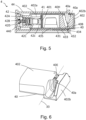
- the sharpening system 4 comprises a retractable mechanism 42 which is arranged on a side wall 440 of the base 44.
- the retractable mechanism 42 is a system of the retractable ballpoint pen type.
- the retractable mechanism 42 includes a spring 42D, a cam 42B, a plug 42A and a piston 42C.
- the principle of such a retractable mechanism is well known to those skilled in the art, in particular in the document US3137276 . Thus, we will not detail in the present invention the principle of the retractable mechanism 42.
- the retracting mechanism 42 includes a disc-shaped magnetic element 41 which is arranged in a cylindrical cavity 42c of the piston 42C.
- magnetic element we understand a permanent magnet which can exert an attraction force on any ferromagnetic material.
- the magnetic element 41 can for example be a neodymium magnet.
- the base 40 comprises a ferromagnetic plate 401 which is arranged vertically on a bottom wall 435 of the base 40.
- the magnetic element 41 exerts an attraction force on the ferromagnetic plate 401 to allow the base 40 to be held to the piston 42C of the mechanism. retractable 42.
- the base 40 comprises a plastic body 402.
- the ferromagnetic plate 401 is arranged inside the plastic body 402.
- the plastic body 402 comprises an intermediate wall 402a which is placed between the magnetic element 41 and the ferromagnetic plate 401 in order to avoid direct contact between the magnetic element 41 and the ferromagnetic plate 401. Thus, the ferromagnetic plate 401 is protected by the plastic body 402 against oxidation.
- the piston 42C of the retractable mechanism 42 is movable in translation along the transverse direction 11 between an in position in which the base 40 is in its storage position and an out position in which the base 40 is in its gripping position.
- the base 40 follows the translational movement of the piston 42C when the base 40 is held to the piston 42C by the element magnetic 41.
- the retractable mechanism 42 makes it possible to maneuver the base 40 quickly between its storage position and its gripping position, by simply pushing on the plastic body 402 of the base 40.
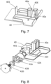
- the sharpening system 4 comprises a device 43 for holding the base 40 in its storage position.
- the piston 42C of the retractable mechanism 42 is not held in position and has a free stroke due to the construction of the retractable mechanism 42.
- this free stroke of the piston 42C is in particular linked to the geometry of the grooves 42a of the plug 42A.
- the holding device 43 therefore makes it possible to hold the base 40 in its storage position and to prevent it from moving on its free stroke.
- the holding device 43 comprises a lamella 431, one free end 432 of which is provided with a protrusion 433 as well as a boss 434 arranged on the bottom wall 435 of the base 40.
- the protuberance 433 at the free end 432 of the strip 431 is arranged behind the boss 434 when the base 40 is in its storage position allowing the base 40 to be locked in its storage position.
- the spring 42D of the retractable mechanism 42 is configured to apply a return force on the base 40 to cause a deformation of the slat 431 allowing the protrusion 433 to pass below the boss 434 so that the base 40 leaves its storage position towards its gripping position.
- the sharpening system 4 comprises two sharpening members 40a which are installed on the base 40, the two sharpening members 40a being integral with the base 40.
- the two sharpening members 40a in the form of a cylinder are made made of a very hard material, for example tungsten.
- Each sharpening member 40a has an upper end 40H and a lower end 40B.
- a knife blade insertion inlet 40E is formed between two upper ends 40H of the two sharpening members 40a.
- the two sharpening members 40a are arranged side by side so that they form a V-shaped sharpening zone along a longitudinal direction 33 perpendicular to the transverse direction 11.
- the user when the user wishes to perform a sharpening operation of the blade of a knife, he first pushes with his finger in the transverse direction 11 on an outer surface 402b of the plastic body 402 of the base 40 in position of storage. Under the action of the user, the spring 42D of the retractable mechanism 42 is compressed to restore a return force on the base 40 to cause a deformation of the strip 431 allowing the protuberance 433 to pass below the boss 434. Thus, the base 40 leaves its storage position towards its gripping position.
- the user grasps a gripping zone of the plastic body 402 which has come out of the frame 2 and pulls the assembly of the base 40 in order to overcome the force of attraction of the magnetic element 41 to make it possible to separate the base 40 from the support 1.
- the user can carry the base 40 comprising the sharpening members 40a in a suitable place, for example on the edge of a work surface to carry out a sharpening operation of the blade of a knife.
- the user grasps the base 40 and approaches it towards its gripping position in the frame 2.
- the base 40 is then attracted and held to the retractable mechanism 42 by the magnetic element 41.
- the user pushes the base 40 to move it from its gripping position to its storage position and the protuberance 433 of the slat 431 passes behind the boss 434 in order to immobilize the base 40 in its storage position . Consequently, the base 40 is stored in the frame 2.
- the holding of the base to the sharpening system can be achieved by two magnetic elements which attract each other, one of which is fixed to the base and the other is fixed to the retractable mechanism.
- the base is movable in translation along the direction of vertical extension of the frame.
Landscapes
- Engineering & Computer Science (AREA)
- Mechanical Engineering (AREA)
- Food Science & Technology (AREA)
- Finish Polishing, Edge Sharpening, And Grinding By Specific Grinding Devices (AREA)
- Knives (AREA)
- Workshop Equipment, Work Benches, Supports, Or Storage Means (AREA)
- Crystals, And After-Treatments Of Crystals (AREA)
- Processing Of Stones Or Stones Resemblance Materials (AREA)
Applications Claiming Priority (1)
| Application Number | Priority Date | Filing Date | Title |
|---|---|---|---|
| FR1759857A FR3072550B1 (fr) | 2017-10-19 | 2017-10-19 | Support de couteaux avec systeme d'affutage |
Publications (2)
| Publication Number | Publication Date |
|---|---|
| EP3473141A1 EP3473141A1 (fr) | 2019-04-24 |
| EP3473141B1 true EP3473141B1 (fr) | 2023-03-22 |
Family
ID=61003141
Family Applications (1)
| Application Number | Title | Priority Date | Filing Date |
|---|---|---|---|
| EP18200579.3A Active EP3473141B1 (fr) | 2017-10-19 | 2018-10-16 | Support de couteaux avec systeme d affûtage |
Country Status (5)
| Country | Link |
|---|---|
| EP (1) | EP3473141B1 (ja) |
| JP (1) | JP7325174B2 (ja) |
| CN (2) | CN209518793U (ja) |
| ES (1) | ES2942412T3 (ja) |
| FR (1) | FR3072550B1 (ja) |
Families Citing this family (5)
| Publication number | Priority date | Publication date | Assignee | Title |
|---|---|---|---|---|
| FR3072550B1 (fr) * | 2017-10-19 | 2021-01-01 | Seb Sa | Support de couteaux avec systeme d'affutage |
| JP6704558B1 (ja) | 2020-01-29 | 2020-06-03 | 株式会社貝印刃物開発センター | 刃物収納具 |
| US10980366B1 (en) | 2020-01-29 | 2021-04-20 | Kai R&D Center Co., Ltd. | Edged tool storage device set |
| US11376713B1 (en) | 2021-03-09 | 2022-07-05 | Sharkninja Operating Llc | Knife sharpening systems |
| CN218500163U (zh) * | 2022-09-21 | 2023-02-21 | V尼维斯有限责任公司 | 具有磨刀器的刀叉收纳盒 |
Family Cites Families (10)
| Publication number | Priority date | Publication date | Assignee | Title |
|---|---|---|---|---|
| DE20319328U1 (de) * | 2003-12-12 | 2004-03-04 | Warimex Waren-Import-Export Handels Gmbh | Block zur Aufnahme von Messern und anderen Küchenutensilien |
| CN2862928Y (zh) * | 2005-10-21 | 2007-01-31 | 曾令东 | 一种带有磨刀器的刀座架 |
| US9149914B2 (en) * | 2012-05-10 | 2015-10-06 | Elemental Tools, Llc | Knife block systems |
| CN103519721B (zh) * | 2013-10-28 | 2015-07-01 | 无锡艾科瑞思产品设计与研究有限公司 | 一种带磨刀器的刀架组合架 |
| CN104552040A (zh) * | 2014-12-23 | 2015-04-29 | 中山市泰帝科技有限公司 | 一种多功能便携式磨刀器 |
| CN204394348U (zh) * | 2015-01-28 | 2015-06-17 | 瑞安市金裕铝业有限公司 | 多功能刀架 |
| CN205083336U (zh) * | 2015-10-25 | 2016-03-16 | 石佳潼 | 一种可防止菜蔬洒落的菜板 |
| US9744649B2 (en) * | 2016-01-07 | 2017-08-29 | Richard A. Williams | SUB (sound utility block) |
| FR3072550B1 (fr) * | 2017-10-19 | 2021-01-01 | Seb Sa | Support de couteaux avec systeme d'affutage |
| CN210697069U (zh) * | 2019-11-12 | 2020-06-09 | 北京林业大学 | 刀座及刀具组合 |
-
2017
- 2017-10-19 FR FR1759857A patent/FR3072550B1/fr active Active
-
2018
- 2018-10-15 JP JP2018194518A patent/JP7325174B2/ja active Active
- 2018-10-16 EP EP18200579.3A patent/EP3473141B1/fr active Active
- 2018-10-16 ES ES18200579T patent/ES2942412T3/es active Active
- 2018-10-19 CN CN201821700589.6U patent/CN209518793U/zh active Active
- 2018-10-19 CN CN201811221854.7A patent/CN109691916A/zh active Pending
Also Published As
| Publication number | Publication date |
|---|---|
| ES2942412T3 (es) | 2023-06-01 |
| CN109691916A (zh) | 2019-04-30 |
| JP7325174B2 (ja) | 2023-08-14 |
| FR3072550A1 (fr) | 2019-04-26 |
| JP2019077030A (ja) | 2019-05-23 |
| EP3473141A1 (fr) | 2019-04-24 |
| FR3072550B1 (fr) | 2021-01-01 |
| CN209518793U (zh) | 2019-10-22 |
Similar Documents
| Publication | Publication Date | Title |
|---|---|---|
| EP3473141B1 (fr) | Support de couteaux avec systeme d affûtage | |
| EP1273399B1 (fr) | Dispositif de coupe à lame rétractable. | |
| WO2014029949A1 (fr) | Dispositif amovible d'attache sur objets longilignes ou filiformes | |
| EP2493661B1 (fr) | Dispositif de maintien d'un outil à main et kit comprenant un tel dispositif | |
| EP1712434A1 (fr) | Butée rétractable au choc pour véhicule automobile | |
| FR2986466A1 (fr) | Instrument d'ecriture a element protecteur de pointe retractable | |
| EP3728059B1 (fr) | Bouteille munie d'un dispositif de verrouillage dans le bouchon | |
| FR2643022A1 (fr) | Dispositif destine a etre utilise avec des etiquettes auto-adhesives amovibles | |
| EP0665086A1 (fr) | Fourreau aiguiseur adapté à recevoir un couteau et combinaison d'un tel fourreau et d'un couteau | |
| EP0468899B1 (fr) | Système de fixation démontable d'un élément par rapport à un organe fixe, ledit élément étant notamment un enjoliveur de roue de véhicule | |
| FR3058136A1 (fr) | Tire-bouchon a double levier. | |
| CH670569A5 (ja) | ||
| FR2925422A1 (fr) | Dispositif de maintien d'un objet sur une paroi interieure de vehicule automobile | |
| FR3058350A1 (fr) | Cutter avec une roulette pour controler la pression de coupe | |
| FR2726217A1 (fr) | Couteau d'ebarbage et nettoyage de pare-brise de vehicules automobiles | |
| FR2666268A1 (fr) | Couteau de decoupe a lame retractable. | |
| WO2021209196A1 (fr) | Combinaison d'un fourreau et d'un couteau | |
| FR2801239A1 (fr) | Couteau d'ebarbage et nettoyage de pare-brise, a cache-lame basculant et mini-poignee | |
| WO2021209194A1 (fr) | Fourreau aiguiseur adapte pour recevoir un couteau et combinaison d'un tel fourreau et d'un couteau | |
| BE1022515B1 (fr) | Machine pour couper automatiquement un pain en tranches avec support frontal | |
| FR3012567A1 (fr) | Systeme de verrouillage d’un support pour appareil nomade reglable en hauteur | |
| EP0725707B1 (fr) | Outil a main extra-plat pour polir ou ebavurer | |
| EP1798008B1 (fr) | Couteau de poche muni d'un coupe-ongle | |
| EP4135931A1 (fr) | Fourreau aiguiseur adapte a recevoir un couteau et combinaison d'un tel fourreau et d'un couteau | |
| FR3002876A1 (fr) | Agencement de couteau pliant |
Legal Events
| Date | Code | Title | Description |
|---|---|---|---|
| PUAI | Public reference made under article 153(3) epc to a published international application that has entered the european phase |
Free format text: ORIGINAL CODE: 0009012 |
|
| STAA | Information on the status of an ep patent application or granted ep patent |
Free format text: STATUS: THE APPLICATION HAS BEEN PUBLISHED |
|
| AK | Designated contracting states |
Kind code of ref document: A1 Designated state(s): AL AT BE BG CH CY CZ DE DK EE ES FI FR GB GR HR HU IE IS IT LI LT LU LV MC MK MT NL NO PL PT RO RS SE SI SK SM TR |
|
| AX | Request for extension of the european patent |
Extension state: BA ME |
|
| STAA | Information on the status of an ep patent application or granted ep patent |
Free format text: STATUS: REQUEST FOR EXAMINATION WAS MADE |
|
| 17P | Request for examination filed |
Effective date: 20191018 |
|
| RBV | Designated contracting states (corrected) |
Designated state(s): AL AT BE BG CH CY CZ DE DK EE ES FI FR GB GR HR HU IE IS IT LI LT LU LV MC MK MT NL NO PL PT RO RS SE SI SK SM TR |
|
| STAA | Information on the status of an ep patent application or granted ep patent |
Free format text: STATUS: EXAMINATION IS IN PROGRESS |
|
| 17Q | First examination report despatched |
Effective date: 20210426 |
|
| STAA | Information on the status of an ep patent application or granted ep patent |
Free format text: STATUS: EXAMINATION IS IN PROGRESS |
|
| GRAP | Despatch of communication of intention to grant a patent |
Free format text: ORIGINAL CODE: EPIDOSNIGR1 |
|
| STAA | Information on the status of an ep patent application or granted ep patent |
Free format text: STATUS: GRANT OF PATENT IS INTENDED |
|
| INTG | Intention to grant announced |
Effective date: 20221020 |
|
| GRAS | Grant fee paid |
Free format text: ORIGINAL CODE: EPIDOSNIGR3 |
|
| GRAA | (expected) grant |
Free format text: ORIGINAL CODE: 0009210 |
|
| STAA | Information on the status of an ep patent application or granted ep patent |
Free format text: STATUS: THE PATENT HAS BEEN GRANTED |
|
| AK | Designated contracting states |
Kind code of ref document: B1 Designated state(s): AL AT BE BG CH CY CZ DE DK EE ES FI FR GB GR HR HU IE IS IT LI LT LU LV MC MK MT NL NO PL PT RO RS SE SI SK SM TR |
|
| REG | Reference to a national code |
Ref country code: GB Ref legal event code: FG4D Free format text: NOT ENGLISH |
|
| REG | Reference to a national code |
Ref country code: CH Ref legal event code: EP |
|
| REG | Reference to a national code |
Ref country code: IE Ref legal event code: FG4D Free format text: LANGUAGE OF EP DOCUMENT: FRENCH |
|
| REG | Reference to a national code |
Ref country code: DE Ref legal event code: R096 Ref document number: 602018047432 Country of ref document: DE |
|
| REG | Reference to a national code |
Ref country code: AT Ref legal event code: REF Ref document number: 1554771 Country of ref document: AT Kind code of ref document: T Effective date: 20230415 |
|
| REG | Reference to a national code |
Ref country code: ES Ref legal event code: FG2A Ref document number: 2942412 Country of ref document: ES Kind code of ref document: T3 Effective date: 20230601 |
|
| REG | Reference to a national code |
Ref country code: LT Ref legal event code: MG9D |
|
| REG | Reference to a national code |
Ref country code: NL Ref legal event code: MP Effective date: 20230322 |
|
| PG25 | Lapsed in a contracting state [announced via postgrant information from national office to epo] |
Ref country code: RS Free format text: LAPSE BECAUSE OF FAILURE TO SUBMIT A TRANSLATION OF THE DESCRIPTION OR TO PAY THE FEE WITHIN THE PRESCRIBED TIME-LIMIT Effective date: 20230322 Ref country code: NO Free format text: LAPSE BECAUSE OF FAILURE TO SUBMIT A TRANSLATION OF THE DESCRIPTION OR TO PAY THE FEE WITHIN THE PRESCRIBED TIME-LIMIT Effective date: 20230622 Ref country code: LV Free format text: LAPSE BECAUSE OF FAILURE TO SUBMIT A TRANSLATION OF THE DESCRIPTION OR TO PAY THE FEE WITHIN THE PRESCRIBED TIME-LIMIT Effective date: 20230322 Ref country code: LT Free format text: LAPSE BECAUSE OF FAILURE TO SUBMIT A TRANSLATION OF THE DESCRIPTION OR TO PAY THE FEE WITHIN THE PRESCRIBED TIME-LIMIT Effective date: 20230322 Ref country code: HR Free format text: LAPSE BECAUSE OF FAILURE TO SUBMIT A TRANSLATION OF THE DESCRIPTION OR TO PAY THE FEE WITHIN THE PRESCRIBED TIME-LIMIT Effective date: 20230322 |
|
| REG | Reference to a national code |
Ref country code: AT Ref legal event code: MK05 Ref document number: 1554771 Country of ref document: AT Kind code of ref document: T Effective date: 20230322 |
|
| PG25 | Lapsed in a contracting state [announced via postgrant information from national office to epo] |
Ref country code: SE Free format text: LAPSE BECAUSE OF FAILURE TO SUBMIT A TRANSLATION OF THE DESCRIPTION OR TO PAY THE FEE WITHIN THE PRESCRIBED TIME-LIMIT Effective date: 20230322 Ref country code: NL Free format text: LAPSE BECAUSE OF FAILURE TO SUBMIT A TRANSLATION OF THE DESCRIPTION OR TO PAY THE FEE WITHIN THE PRESCRIBED TIME-LIMIT Effective date: 20230322 Ref country code: GR Free format text: LAPSE BECAUSE OF FAILURE TO SUBMIT A TRANSLATION OF THE DESCRIPTION OR TO PAY THE FEE WITHIN THE PRESCRIBED TIME-LIMIT Effective date: 20230623 Ref country code: FI Free format text: LAPSE BECAUSE OF FAILURE TO SUBMIT A TRANSLATION OF THE DESCRIPTION OR TO PAY THE FEE WITHIN THE PRESCRIBED TIME-LIMIT Effective date: 20230322 |
|
| PG25 | Lapsed in a contracting state [announced via postgrant information from national office to epo] |
Ref country code: SM Free format text: LAPSE BECAUSE OF FAILURE TO SUBMIT A TRANSLATION OF THE DESCRIPTION OR TO PAY THE FEE WITHIN THE PRESCRIBED TIME-LIMIT Effective date: 20230322 Ref country code: RO Free format text: LAPSE BECAUSE OF FAILURE TO SUBMIT A TRANSLATION OF THE DESCRIPTION OR TO PAY THE FEE WITHIN THE PRESCRIBED TIME-LIMIT Effective date: 20230322 Ref country code: PT Free format text: LAPSE BECAUSE OF FAILURE TO SUBMIT A TRANSLATION OF THE DESCRIPTION OR TO PAY THE FEE WITHIN THE PRESCRIBED TIME-LIMIT Effective date: 20230724 Ref country code: EE Free format text: LAPSE BECAUSE OF FAILURE TO SUBMIT A TRANSLATION OF THE DESCRIPTION OR TO PAY THE FEE WITHIN THE PRESCRIBED TIME-LIMIT Effective date: 20230322 Ref country code: AT Free format text: LAPSE BECAUSE OF FAILURE TO SUBMIT A TRANSLATION OF THE DESCRIPTION OR TO PAY THE FEE WITHIN THE PRESCRIBED TIME-LIMIT Effective date: 20230322 |
|
| PG25 | Lapsed in a contracting state [announced via postgrant information from national office to epo] |
Ref country code: SK Free format text: LAPSE BECAUSE OF FAILURE TO SUBMIT A TRANSLATION OF THE DESCRIPTION OR TO PAY THE FEE WITHIN THE PRESCRIBED TIME-LIMIT Effective date: 20230322 Ref country code: PL Free format text: LAPSE BECAUSE OF FAILURE TO SUBMIT A TRANSLATION OF THE DESCRIPTION OR TO PAY THE FEE WITHIN THE PRESCRIBED TIME-LIMIT Effective date: 20230322 Ref country code: IS Free format text: LAPSE BECAUSE OF FAILURE TO SUBMIT A TRANSLATION OF THE DESCRIPTION OR TO PAY THE FEE WITHIN THE PRESCRIBED TIME-LIMIT Effective date: 20230722 |
|
| REG | Reference to a national code |
Ref country code: DE Ref legal event code: R097 Ref document number: 602018047432 Country of ref document: DE |
|
| PGFP | Annual fee paid to national office [announced via postgrant information from national office to epo] |
Ref country code: GB Payment date: 20231019 Year of fee payment: 6 |
|
| PGFP | Annual fee paid to national office [announced via postgrant information from national office to epo] |
Ref country code: ES Payment date: 20231114 Year of fee payment: 6 |
|
| PLBE | No opposition filed within time limit |
Free format text: ORIGINAL CODE: 0009261 |
|
| STAA | Information on the status of an ep patent application or granted ep patent |
Free format text: STATUS: NO OPPOSITION FILED WITHIN TIME LIMIT |
|
| PG25 | Lapsed in a contracting state [announced via postgrant information from national office to epo] |
Ref country code: SI Free format text: LAPSE BECAUSE OF FAILURE TO SUBMIT A TRANSLATION OF THE DESCRIPTION OR TO PAY THE FEE WITHIN THE PRESCRIBED TIME-LIMIT Effective date: 20230322 Ref country code: DK Free format text: LAPSE BECAUSE OF FAILURE TO SUBMIT A TRANSLATION OF THE DESCRIPTION OR TO PAY THE FEE WITHIN THE PRESCRIBED TIME-LIMIT Effective date: 20230322 Ref country code: CZ Free format text: LAPSE BECAUSE OF FAILURE TO SUBMIT A TRANSLATION OF THE DESCRIPTION OR TO PAY THE FEE WITHIN THE PRESCRIBED TIME-LIMIT Effective date: 20230322 |
|
| PGFP | Annual fee paid to national office [announced via postgrant information from national office to epo] |
Ref country code: FR Payment date: 20231023 Year of fee payment: 6 Ref country code: DE Payment date: 20231011 Year of fee payment: 6 |
|
| 26N | No opposition filed |
Effective date: 20240102 |
|
| PGFP | Annual fee paid to national office [announced via postgrant information from national office to epo] |
Ref country code: BE Payment date: 20231016 Year of fee payment: 6 |