EP3471117A1 - Unité d'alimentation, système d'alimentation et dispositif électronique - Google Patents
Unité d'alimentation, système d'alimentation et dispositif électronique Download PDFInfo
- Publication number
- EP3471117A1 EP3471117A1 EP18205975.8A EP18205975A EP3471117A1 EP 3471117 A1 EP3471117 A1 EP 3471117A1 EP 18205975 A EP18205975 A EP 18205975A EP 3471117 A1 EP3471117 A1 EP 3471117A1
- Authority
- EP
- European Patent Office
- Prior art keywords
- power transmission
- coil
- auxiliary
- resonance
- section
- Prior art date
- Legal status (The legal status is an assumption and is not a legal conclusion. Google has not performed a legal analysis and makes no representation as to the accuracy of the status listed.)
- Granted
Links
- 230000005540 biological transmission Effects 0.000 claims abstract description 370
- 230000001747 exhibiting effect Effects 0.000 claims description 7
- 239000003990 capacitor Substances 0.000 description 39
- 230000004907 flux Effects 0.000 description 32
- 230000000052 comparative effect Effects 0.000 description 31
- 238000009826 distribution Methods 0.000 description 31
- 230000008859 change Effects 0.000 description 22
- 230000006870 function Effects 0.000 description 20
- 238000004804 winding Methods 0.000 description 19
- 230000000694 effects Effects 0.000 description 17
- 238000010586 diagram Methods 0.000 description 14
- 230000007423 decrease Effects 0.000 description 13
- 230000001419 dependent effect Effects 0.000 description 10
- 230000008878 coupling Effects 0.000 description 9
- 238000010168 coupling process Methods 0.000 description 9
- 238000005859 coupling reaction Methods 0.000 description 9
- 238000000034 method Methods 0.000 description 8
- 230000004044 response Effects 0.000 description 8
- 230000003071 parasitic effect Effects 0.000 description 7
- 230000009467 reduction Effects 0.000 description 5
- 239000003381 stabilizer Substances 0.000 description 5
- 230000005674 electromagnetic induction Effects 0.000 description 4
- 238000004519 manufacturing process Methods 0.000 description 4
- 229910052751 metal Inorganic materials 0.000 description 4
- 239000002184 metal Substances 0.000 description 4
- 239000004020 conductor Substances 0.000 description 3
- 238000005516 engineering process Methods 0.000 description 3
- 230000006872 improvement Effects 0.000 description 3
- 230000001629 suppression Effects 0.000 description 3
- 239000000696 magnetic material Substances 0.000 description 2
- 238000001646 magnetic resonance method Methods 0.000 description 2
- 230000004048 modification Effects 0.000 description 2
- 238000012986 modification Methods 0.000 description 2
- 230000002093 peripheral effect Effects 0.000 description 2
- 230000006641 stabilisation Effects 0.000 description 2
- 238000011105 stabilization Methods 0.000 description 2
- 239000000126 substance Substances 0.000 description 2
- HBBGRARXTFLTSG-UHFFFAOYSA-N Lithium ion Chemical compound [Li+] HBBGRARXTFLTSG-UHFFFAOYSA-N 0.000 description 1
- 230000009471 action Effects 0.000 description 1
- 230000008901 benefit Effects 0.000 description 1
- 230000015572 biosynthetic process Effects 0.000 description 1
- 238000004891 communication Methods 0.000 description 1
- 238000013461 design Methods 0.000 description 1
- 230000005684 electric field Effects 0.000 description 1
- 230000006698 induction Effects 0.000 description 1
- 229910001416 lithium ion Inorganic materials 0.000 description 1
- 239000000203 mixture Substances 0.000 description 1
- 239000000025 natural resin Substances 0.000 description 1
- 238000005457 optimization Methods 0.000 description 1
- 238000009774 resonance method Methods 0.000 description 1
- 229920003002 synthetic resin Polymers 0.000 description 1
- 239000000057 synthetic resin Substances 0.000 description 1
- 238000013519 translation Methods 0.000 description 1
Images


Classifications
-
- H—ELECTRICITY
- H01—ELECTRIC ELEMENTS
- H01F—MAGNETS; INDUCTANCES; TRANSFORMERS; SELECTION OF MATERIALS FOR THEIR MAGNETIC PROPERTIES
- H01F38/00—Adaptations of transformers or inductances for specific applications or functions
- H01F38/14—Inductive couplings
-
- H—ELECTRICITY
- H01—ELECTRIC ELEMENTS
- H01F—MAGNETS; INDUCTANCES; TRANSFORMERS; SELECTION OF MATERIALS FOR THEIR MAGNETIC PROPERTIES
- H01F27/00—Details of transformers or inductances, in general
- H01F27/006—Details of transformers or inductances, in general with special arrangement or spacing of turns of the winding(s), e.g. to produce desired self-resonance
-
- H—ELECTRICITY
- H01—ELECTRIC ELEMENTS
- H01F—MAGNETS; INDUCTANCES; TRANSFORMERS; SELECTION OF MATERIALS FOR THEIR MAGNETIC PROPERTIES
- H01F27/00—Details of transformers or inductances, in general
- H01F27/06—Mounting, supporting or suspending transformers, reactors or choke coils not being of the signal type
-
- H—ELECTRICITY
- H02—GENERATION; CONVERSION OR DISTRIBUTION OF ELECTRIC POWER
- H02J—CIRCUIT ARRANGEMENTS OR SYSTEMS FOR SUPPLYING OR DISTRIBUTING ELECTRIC POWER; SYSTEMS FOR STORING ELECTRIC ENERGY
- H02J50/00—Circuit arrangements or systems for wireless supply or distribution of electric power
- H02J50/10—Circuit arrangements or systems for wireless supply or distribution of electric power using inductive coupling
- H02J50/12—Circuit arrangements or systems for wireless supply or distribution of electric power using inductive coupling of the resonant type
-
- H—ELECTRICITY
- H02—GENERATION; CONVERSION OR DISTRIBUTION OF ELECTRIC POWER
- H02J—CIRCUIT ARRANGEMENTS OR SYSTEMS FOR SUPPLYING OR DISTRIBUTING ELECTRIC POWER; SYSTEMS FOR STORING ELECTRIC ENERGY
- H02J50/00—Circuit arrangements or systems for wireless supply or distribution of electric power
- H02J50/40—Circuit arrangements or systems for wireless supply or distribution of electric power using two or more transmitting or receiving devices
- H02J50/402—Circuit arrangements or systems for wireless supply or distribution of electric power using two or more transmitting or receiving devices the two or more transmitting or the two or more receiving devices being integrated in the same unit, e.g. power mats with several coils or antennas with several sub-antennas
-
- H—ELECTRICITY
- H02—GENERATION; CONVERSION OR DISTRIBUTION OF ELECTRIC POWER
- H02J—CIRCUIT ARRANGEMENTS OR SYSTEMS FOR SUPPLYING OR DISTRIBUTING ELECTRIC POWER; SYSTEMS FOR STORING ELECTRIC ENERGY
- H02J50/00—Circuit arrangements or systems for wireless supply or distribution of electric power
- H02J50/70—Circuit arrangements or systems for wireless supply or distribution of electric power involving the reduction of electric, magnetic or electromagnetic leakage fields
-
- H—ELECTRICITY
- H02—GENERATION; CONVERSION OR DISTRIBUTION OF ELECTRIC POWER
- H02J—CIRCUIT ARRANGEMENTS OR SYSTEMS FOR SUPPLYING OR DISTRIBUTING ELECTRIC POWER; SYSTEMS FOR STORING ELECTRIC ENERGY
- H02J50/00—Circuit arrangements or systems for wireless supply or distribution of electric power
- H02J50/90—Circuit arrangements or systems for wireless supply or distribution of electric power involving detection or optimisation of position, e.g. alignment
-
- H—ELECTRICITY
- H01—ELECTRIC ELEMENTS
- H01M—PROCESSES OR MEANS, e.g. BATTERIES, FOR THE DIRECT CONVERSION OF CHEMICAL ENERGY INTO ELECTRICAL ENERGY
- H01M10/00—Secondary cells; Manufacture thereof
- H01M10/42—Methods or arrangements for servicing or maintenance of secondary cells or secondary half-cells
- H01M10/46—Accumulators structurally combined with charging apparatus
-
- H—ELECTRICITY
- H02—GENERATION; CONVERSION OR DISTRIBUTION OF ELECTRIC POWER
- H02J—CIRCUIT ARRANGEMENTS OR SYSTEMS FOR SUPPLYING OR DISTRIBUTING ELECTRIC POWER; SYSTEMS FOR STORING ELECTRIC ENERGY
- H02J7/00—Circuit arrangements for charging or depolarising batteries or for supplying loads from batteries
- H02J7/00032—Circuit arrangements for charging or depolarising batteries or for supplying loads from batteries characterised by data exchange
- H02J7/00045—Authentication, i.e. circuits for checking compatibility between one component, e.g. a battery or a battery charger, and another component, e.g. a power source
-
- Y—GENERAL TAGGING OF NEW TECHNOLOGICAL DEVELOPMENTS; GENERAL TAGGING OF CROSS-SECTIONAL TECHNOLOGIES SPANNING OVER SEVERAL SECTIONS OF THE IPC; TECHNICAL SUBJECTS COVERED BY FORMER USPC CROSS-REFERENCE ART COLLECTIONS [XRACs] AND DIGESTS
- Y02—TECHNOLOGIES OR APPLICATIONS FOR MITIGATION OR ADAPTATION AGAINST CLIMATE CHANGE
- Y02E—REDUCTION OF GREENHOUSE GAS [GHG] EMISSIONS, RELATED TO ENERGY GENERATION, TRANSMISSION OR DISTRIBUTION
- Y02E60/00—Enabling technologies; Technologies with a potential or indirect contribution to GHG emissions mitigation
- Y02E60/10—Energy storage using batteries
Definitions
- the present disclosure relates to a feed system that performs non-contact electric power supply (electric power transmission) to an electronic device, as well as a feed unit and an electronic device applied to such a feed system.
- a feed system (a non-contact feed system and a wireless charging system) that performs non-contact electric power supply (electric power transmission) to a CE device (Consumer Electronics Device) such as a mobile phone and a portable music player, for example.
- a CE device Consumer Electronics Device
- This makes it possible to start charging merely by placing an electronic device (a secondary-side device) on a charging tray (a primary-side device), instead of starting charging by inserting (connecting) a connector of a power-supply unit such as an AC adapter into the device. In other words, terminal connection between the electronic device and the charging tray becomes unnecessary.
- non-contact feed systems using the electromagnetic resonance phenomenon have such advantages that, due to the principle of the electromagnetic resonance phenomenon, electric power transmission is enabled over a longer distance than that in the electromagnetic induction method, and a decrease in transmission efficiency is small even when alignment of axes is poor to some extent. It is to be noted that concerning this electromagnetic resonance phenomenon, there is an electric-field resonance method, besides the magnetic resonance method. In a non-contact feed system of this magnetic-field resonance type (see, for example, Patent Literatures 1 and 2), precise alignment of axes is not necessary, and extending a feeding distance is also possible.
- the magnetic-flux-line distribution magnetic-flux-density distribution in an inner region of the power transmission coil is nonuniform as described above. Therefore, there is such an issue that feeding efficiency (transmission efficiency) at the time of non-contact feeding is nonuniform by being dependent on the relative position between the primary-side device and the secondary-side device (for example, the placement of the secondary-side device).
- a feed unit includes: a power transmission section including a power transmission coil configured to perform electric power transmission using a magnetic field, and an auxiliary resonance section including one or a plurality of resonators.
- the resonator includes an auxiliary coil wound to form a gap in at least a partial region.
- a feed system includes: one or a plurality of electronic devices; and a feed unit configured to perform electric power transmission to the electronic device.
- the feed unit includes a power transmission section including a power transmission coil configured to perform the electric power transmission using a magnetic field
- the electronic device includes a power receiving section including a power receiving coil configured to receive electric power transmitted from the power transmission section.
- An auxiliary resonance section including one or a plurality of resonators is provided in at least one of the feed unit, the electronic device, and other unit independent of the feed unit and the electronic device.
- the resonator includes an auxiliary coil wound to form a gap in at least a partial region.
- An electronic device includes: a power receiving section including a power receiving coil configured to receive electric power transmitted using a magnetic field, and an auxiliary resonance section including one or a plurality of resonators.
- the resonator includes an auxiliary coil wound to form a gap in at least a partial region.
- the resonator in the auxiliary resonance section includes the auxiliary coil wound to form a gap in at least a partial region. Because such a gap (a gap region) is formed, a change occurs in a relationship (positional characteristics) between a relative position between a feed unit (a power transmission side) and an electronic device (a power receiving side), and transmission efficiency at the time of electric power transmission.
- a main resonance frequency in main resonance operation using the power transmission coil at a time of the electric power transmission, and an auxiliary resonance frequency in the resonator may be made different from each other.
- An adjustment of the difference between such resonance frequencies also causes the change in the positional characteristics.
- the auxiliary resonance frequency may be a frequency higher than the main resonance frequency.
- the resonator in the auxiliary resonance section includes the auxiliary coil wound to form a gap in at least a partial region.
- FIG. 1 illustrates an appearance configuration example of a feed system (a feed system 4) according to a first embodiment of the present disclosure
- FIG. 2 illustrates a block configuration example of this feed system 4.
- the feed system 4 is a system (a non-contact type feed system) that performs electric power transmission (power supply or feeding) in a non-contact manner by using a magnetic field (by utilizing magnetic resonance or the like; likewise hereinafter).
- This feed system 4 includes a feed unit 1 (a primary-side device) and one or a plurality of electronic devices (here, two electronic devices 2A and 2B; secondary-side devices).
- electric power transmission from the feed unit 1 to the electronic devices 2A and 2B may be performed by placing the electronic devices 2A and 2B on (or, in proximity to) a feeding surface (a power transmission surface) S1 in the feed unit 1, as illustrated in FIG. 1 , for example.
- a feeding surface a power transmission surface
- the feed unit 1 is shaped like a mat (a tray) in which the area of the feeding surface S1 is larger than the electronic devices 2A and 2B to be fed and the like.
- the feed unit 1 is a unit (a charging tray) that performs the electric power transmission to the electronic devices 2A and 2B by using a magnetic field as described above.
- This feed unit 1 may include, for example, a power transmission unit 11 that includes a power transmission section 110, a high-frequency power generating circuit 111, an impedance matching circuit 112, and a resonance capacitor (a capacitor) C1 as illustrated in FIG. 2 , for example.
- the power transmission section 110 may include, for example, a power transmission coil (a primary-side coil) L1 and the like to be described later.
- the power transmission section 110 performs electric power transmission using a magnetic field to the electronic devices 2A and 2B (specifically, a power receiving section 210 that will be described later), by utilizing this power transmission coil L1 and the resonance capacitor C1.
- the power transmission section 110 has a function of emitting a magnetic field (a magnetic flux) from the feeding surface S1 towards the electronic devices 2A and 2B. It is to be noted that a detailed configuration of this power transmission section 110 will be described later ( FIG. 3 to FIG. 5 ).
- the high-frequency power generating circuit 111 may be a circuit that generates predetermined high-frequency electric power (an AC signal) used to perform electric power transmission, through use of electric power supplied from a power supply source 9 outside the feed unit 1, for example.
- the impedance matching circuit 112 is a circuit that performs impedance matching when electric power transmission is performed. This improves efficiency (transmission efficiency) at the time of the electric power transmission. It is to be noted that depending on configurations of the power transmission coil L1, a power receiving coil L2 that will be described later, the resonance capacitors C1 and C2, and the like, this impedance matching circuit 112 may not be provided.
- the resonance capacitor C1 is a capacitor used to configure an LC resonator (a main resonator or a main resonance circuit) together with the power transmission coil L1, and is disposed to be electrically connected to the power transmission coil L1 directly, in parallel, or in a combination of series and parallel.
- This LC resonator configured of the power transmission coil L1 and the resonance capacitor C1 performs resonance operation (main resonance operation) based on a resonance frequency (a main resonance frequency) f1 made of a frequency that is substantially equal to or in the vicinity of high-frequency electric power generated in the high-frequency power generating circuit 111. Further, a capacitance value of the resonance capacitor C1 is set to realize such a resonance frequency f1.
- the resonance capacitor C1 may not be provided, when the above-described resonance frequency f1 is realized by main resonance operation using a parasitic capacitance component (a stray capacitance component) configured of a line capacity in the power transmission coil L1, a capacity between the power transmission coil L1 and the power receiving coil L2 that will be described later, and the like.
- a parasitic capacitance component a stray capacitance component
- the electronic devices 2A and 2B each may be, for example, any of stationary electronic devices represented by television receivers, portable electronic devices containing a rechargeable battery (battery) represented by mobile phones and digital cameras, and the like. As illustrated in, for example, FIG. 2 , the electronic devices 2A and 2B each include a power receiving unit 21, and a load 22 that performs predetermined operation (operation of performing functions of serving as the electronic device) based on electric power supplied from this power receiving unit 21. Further, the power receiving unit 21 includes a power receiving section 210, an impedance matching circuit 212, a rectifier circuit 213, a voltage stabilizer 214, a battery 215, and the resonance capacitor (capacitor) C2.
- the power receiving section 210 includes the power receiving coil L2 (a secondary-side coil) that will be described later.
- the power receiving section 210 has a function of receiving electric power transmitted from the power transmission section 110 in the feed unit 1, by utilizing the power receiving coil L2 and the resonance capacitor C2. It is to be noted that a detailed configuration of this power receiving section 210 will be described later ( FIG. 3 ).
- the impedance matching circuit 212 is a circuit that performs impedance matching when electric power transmission is performed, as with the impedance matching circuit 112 described above. It is to be noted that this impedance matching circuit 212 may not be provided, depending on configurations of the power transmission coil L1, the power receiving coil L2 that will be described later, the resonance capacitors C1 and C2, and the like.
- the rectifier circuit 213 is a circuit that rectifies electric power (AC power) supplied from the power receiving section 210, and generates DC power.
- the voltage stabilizer 214 is a circuit that performs predetermined voltage stabilization operation based on the DC power supplied from the rectifier circuit 213, and charges the battery 215 and a battery (not illustrated) in the load 22.
- the battery 215 stores electric power according to the charging by the voltage stabilizer 214, and may be configured using, for example, a rechargeable battery (a secondary battery) such as a lithium ion battery. It is to be noted that this battery 215 may not be necessarily provided, in a case in which, for example, only the battery in the load 22 is used.
- the resonance capacitor C2 is a capacitor used to configure an LC resonator (a main resonator, or a main resonance circuit) together with the power receiving coil L2, and is disposed to be electrically connected to the power receiving coil L2 directly, in parallel, or in a combination of series and parallel.
- This LC resonator configured of the power receiving coil L2 and the resonance capacitor C2 performs resonance operation based on a resonance frequency f2 made of a frequency that is substantially equal to or in the vicinity of high-frequency electric power generated in the high-frequency power generating circuit 111.
- the LC resonator provided in the power transmission unit 11, which is configured using the power transmission coil L1 and the resonance capacitor C1 and the LC resonator provided in the power receiving unit 21, which is configured using the power receiving coil L2 and the resonance capacitor C2, perform the main resonance operation at the resonance frequencies (f1 ⁇ f2) that are substantially equal to each other.
- a capacitance value of the resonance capacitor C2 is set to realize such a resonance frequency f2.
- the resonance capacitor C2 may not be provided either, when the above-described resonance frequency f2 is realized by main resonance operation using a parasitic capacitance component configured of a line capacity in the power receiving coil L2, a capacity between the power transmission coil L1 and the power receiving coil L2, and the like.
- FIG. 3 schematically illustrates a schematic configuration of each of the power transmission section 110 and the power receiving section 210.
- the power transmission section 110 includes the power transmission coil L1 and an auxiliary resonance section 3, and the power receiving section 210 includes the power receiving coil L2.
- the power transmission coil L1 is a coil provided to perform electric power transmission (to generate a magnetic flux) using a magnetic field, as described above.
- the power receiving coil L2 is a coil provided to receive the electric power transmitted from the power transmission section 110 (from the magnetic flux).
- the auxiliary resonance section 3 performs predetermined resonance operation (auxiliary resonance operation), and here includes one LC resonator (an auxiliary resonator, or an auxiliary resonance circuit) configured using one auxiliary coil L3 and one resonance capacitor (a capacitor) C3.
- a resonance frequency (an auxiliary resonance frequency) at the time of the auxiliary resonance operation in the LC resonator in this auxiliary resonance section 3 is assumed to be f3. It is to be noted that this resonance capacitor C3 in the auxiliary resonance section 3 may not be provided either, in cases such as a case in which a predetermined parasitic capacitance component is used in place thereof.
- FIG. 4 illustrates a detailed configuration example of the power transmission section 110
- Part (A) of FIG. 4 illustrates a perspective configuration example
- Part (B) of FIG. 4 illustrates a plane configuration example (an X-Y plane configuration example).
- the power transmission coil L1 and the auxiliary coil L3 which are described above are disposed on a flat-shaped shield board 110S, to be insulated (insulated physically and electrically) from each other.
- the shield board 110S is provided to prevent an unnecessary magnetic flux leakage into a region (here, downward) where there is no coupling (magnetic coupling) with the power receiving coil L2, and is made of a magnetic substance, a conductive material, or the like. However, such a shield board 110S may not be provided in some cases.
- the power transmission coil L1 and the auxiliary coil L3 are disposed substantially in the same surface (here, a surface (the same plane) of the shield board 110S).
- a disposition configuration is not limited thereto, and, for example, the auxiliary coil L3 may be disposed on a plane displaced from a coil surface of the power transmission coil L1, along a vertical direction (a Z-axis direction) thereof.
- the power transmission coil L1 and the auxiliary coil L3 may be disposed in planes different from each other. In a case of such disposition, flexibility of design (disposition) of the auxiliary resonance section 3 improves.
- a center point CP1 of the power transmission coil L1 and a center point CP3 of the auxiliary coil L3 are located substantially on the same axis (the Z-axis) (here, substantially the same point) with respect to each other.
- a structure of the power transmission section 110 that includes the power transmission coil L1 and the auxiliary coil L3 is substantially symmetric in an X-axis direction and a Y-axis direction, making it easier to achieve planarization (equalization) of transmission efficiency distribution according to a relative position (here, a placement position of each of the electronic devices 2A and 2B relative to the feed unit 1) that will be described later.
- an inner diameter ⁇ 3 of the auxiliary coil L3 is made smaller than an inner diameter ⁇ 1 of the power transmission coil L1 ( ⁇ 3 ⁇ ⁇ 1). This makes it possible to reinforce a magnetic field in the vicinity of a central part of the power transmission coil L1, which is relatively weak when the auxiliary coil L3 is not present. In this way, the power transmission coil L1 and the auxiliary coil L3 are formed to have concentric circular shapes whose respective inner diameters are different from each other.
- a winding is provided to form a gap in at least a partial region (a gap region).
- a cavity section is provided between the wire rods that configure this auxiliary coil L3.
- a plurality of gaps are formed from an outer edge side (an outer circumference side) towards an inner edge side (an inner circumference side), in the auxiliary coil L3.
- a winding is non-densely provided to form the plurality of gaps G1 to G3 continuously from an inner edge to an outer edge thereof.
- widths of the gaps G1 to G3 (gap widths g1 to g3) become gradually larger in a direction from the outer edge side towards the center of the auxiliary coil L3.
- the gap width g1 of the gap G1, the gap width g2 of the gap G2, and the gap width g3 of the gap G3 are set to satisfy a relation of g3 > g2 > g1.
- Such a gap may be configured using, for example, a synthetic resin, a natural resin, a magnetic substance, and the like, besides air (a hollow).
- configurations of the power transmission coil L1 and the auxiliary coil L3 in the power transmission section 110 are not limited to those illustrated in Part (A) and Part (B) of FIG. 4 .
- the entire formation region of the auxiliary coil L3 (the entire region ranging from the inner edge to the outer edge) may not be necessarily provided with a gap, and at least a partial region may be provided with a gap.
- the widths of the gaps G1 to G3 may be substantially equal to each other (g3 ⁇ g2 ⁇ g1) or, contrary to the above case, may become gradually smaller in a direction from the outer edge side towards the center of the auxiliary coil L3 (g3 ⁇ g2 ⁇ g1).
- each of the power transmission coil L1 and the auxiliary coil L3 may be, for example, a coil of a clockwise winding, or a coil of a counterclockwise winding, and the respective winding directions may not be necessarily the same. Furthermore, displaced disposition not to locate the center point CP1 of the power transmission coil L1 and the center point CP3 of the auxiliary coil L3 on the same axis may be adopted. In that case, it is possible to intentionally provide unevenness to the transmission efficiency distribution according to the relative position (here, the placement position of each of the electronic devices 2A and 2B relative to the feed unit 1) that will be described later.
- the inner diameter ⁇ 3 of the auxiliary coil L3 may be equal to or more than the inner diameter ⁇ 1 of the power transmission coil L1 ( ⁇ 3 ⁇ ⁇ 1). In that case, although a maximum value of the transmission efficiency decreases, it is possible to expand a region where non-contact feeding is enabled by relatively high transmission efficiency.
- the resonance frequency f1 ( ⁇ f2) in the main resonance operation using the power transmission coil L1 at the time of the electric power transmission and the resonance frequency f3 in the LC resonator in the auxiliary resonance section 3 may be different from each other (f1 ⁇ f3), as illustrated in Part (A) and Part (B) of FIG. 5 .
- the resonance frequency f3 may be a frequency higher than the resonance frequency f1 ( ⁇ f2) (f3 > f1).
- the resonance frequency f3 may be a frequency lower than the resonance frequency f1 ( ⁇ f2) (f3 ⁇ f1).
- the resonance frequency f3 may be, for example, 1.1 times or more and 5.0 times or less the resonance frequency f1 ( ⁇ f2) (1.1 ⁇ (f3/f1) ⁇ 5.0), and more desirably, 1.25 times or more and 3.00 times or less (1.25 ⁇ (f3/f1) ⁇ 3.00).
- the relative position here, the placement position of each of the electronic devices 2A and 2B relative to the feed unit 1.
- the predetermined high-frequency electric power (the AC signal) used to perform the electric power transmission is supplied from the high-frequency power generating circuit 111 to the power transmission coil L1 and the resonance capacitor C1 (the LC resonator) in the power transmission section 110, in the feed unit 1. This causes the magnetic field (the magnetic flux) in the power transmission coil L1 in the power transmission section 110.
- the electronic devices 2A and 2B each serving as a device to be fed are placed on (or, in proximity to) the top surface (the feeding surface S1) of the feed unit 1, the power transmission coil L1 in the feed unit 1 and the power receiving coil L2 in each of the electronic devices 2A and 2B are in proximity to each other in the vicinity of the feeding surface S1.
- the main resonance operation (the resonance frequency f1) using the power transmission coil L1 and the resonance capacitor C1 is performed, and on the electronic devices 2A and 2B side, the main resonance operation (the resonance frequency f2 ⁇ f1) using the power receiving coil L2 and the resonance capacitor C2 is performed.
- the AC power received by the power receiving coil L2 is supplied to the rectifier circuit 213 and the voltage stabilizer 214, and the following charging operation is performed. That is, after this AC power is converted into predetermined DC power by the rectifier circuit 213, the voltage stabilization operation based on this DC power is performed by the voltage stabilizer 214, and the charging of the battery 215 or the battery (not illustrated) in the load 22 is performed. In this way, in each of the electronic devices 2A and 2B, the charging operation based on the electric power received by the power receiving section 210 is performed.
- terminal connection to an AC adapter or the like may be unnecessary, and it is possible to start the charging easily by merely placing the electronic devices 2A and 2B on (or in proximity to) the feeding surface S1 of the feed unit 1 (non-contact feeding is performed). This reduces burden on a user.
- auxiliary resonance section 3 which is one of characteristic parts in the present embodiment, will be described in detail in comparison with a comparative example (comparative examples 1 to 3).
- FIG. 6 illustrates a schematic configuration of a feed system (a feed system 104) (Part (A) of FIG. 6 ) and power transmission characteristics (Part (B) of FIG. 6 ) according to a comparative example 1.
- the feed system 104 of this comparative example 1 is a system that performs non-contact electric power transmission using a magnetic field, as with the feed system 4 (see electric power PI01 in Part (A) of FIG. 6 ).
- the feed system 104 includes a feed unit (not illustrated) having a power transmission unit 101, and an electronic device (not illustrated) having a power receiving unit 21.
- the power transmission unit 101 includes the power transmission coil L1, but does not include the auxiliary resonance section 3 unlike the power transmission unit 11.
- a reason for this is as follows.
- transmission efficiency at the time of the electric power transmission is nonuniform by being dependent on the relative position between the primary-side device and the secondary-side device (here, the position of the secondary-side device).
- This causes a decline in flexibility of the relative position (here, flexibility of placing the secondary-side device on the feeding surface of the primary-side device) at the time of the electric power transmission, and impairs convenience of a user.
- a relationship between the relative position between the primary-side device (the feed unit, or the power transmission side) and the secondary-side device (the electronic device, or the power receiving surface), and the transmission efficiency at the time of the electric power transmission is defined and described as "positional characteristics".
- a power transmission section 201A having a plane configuration (an X-Y plane configuration) illustrated in Part (A) of FIG. 7 , for example.
- This power transmission section 201A includes a power transmission coil L201 configured of two coils (split coils) of an outer circumference coil L201A and an inner circumference coil L201B.
- the outer circumference coil L201A and the inner circumference coil L201B are disposed a predetermined distance (an inner diameter difference) apart from each other over.
- this power transmission coil L201 unlike the power transmission coil L1 and the auxiliary coil L3 (which are physically and electrically insulated) of the present embodiment described above, the outer circumference coil L201A and the inner circumference coil L201B are connected (not insulated) physically and electrically.
- a direction of a magnetic flux generated by the outer circumference coil L201A and a direction of a magnetic flux generated by the inner circumference coil L201B are set to be the same (here, a forward direction on a Z-axis).
- a placement region (a dead band) where transmission efficiency is considerably reduced may be present, depending on the relative position (here, the position of a secondary-side device (a power receiving coil)) at the time of the electric power transmission.
- a reason for this is as follows. That is, first, when the power receiving coil is placed in a region in and above the inner circumference coil L201B, in this region, the directions of the magnetic fluxes by the outer circumference coil L201A and the directions of the magnetic fluxes by the inner circumference coil L201B agree with each other (in the forward direction on the Z-axis) as described above.
- the directions of the magnetic fluxes by the outer circumference coil L201A and the directions of the magnetic fluxes by the inner circumference coil L201B disagree with each other and are partially opposite to each other. Describing using an extreme example, as indicated with the arrows of the solid lines and the broken lines in Part (B) of FIG. 7 , the directions of the magnetic fluxes by the outer circumference coil L201A and the directions of the magnetic fluxes by the inner circumference coil L201B become all opposite to each other.
- the magnetic fluxes are partially offset equivalently and therefore, an increase in the magnetic flux density is suppressed to some extent in the vicinity of an inner end of the outer circumference coil L201A.
- the directions of the magnetic fluxes equivalently passing through the power receiving coil are determined by a balance between the magnetic flux density of the magnetic flux lines generated from the outer circumference coil L201A and the magnetic flux density of the magnetic flux lines generated from the inner circumference coil L201B, in the vicinity of the power receiving coil.
- the placement region (a dead band) where the transmission efficiency considerably decreases may be present, depending on the relative position (the position of the secondary-side device) at the time of the electric power transmission. It is to be noted that when split coils similar to those of the comparative example 2 are used as the power transmission coil, the same high-frequency electric power is applied to each of the outer circumference coil and the inner circumference coil and thus, such an issue of occurrence of a dead band is not avoidable.
- a power transmission section 301 having a plane configuration (an X-Y plane configuration) as illustrated in FIG. 8 for example.
- the power transmission coil L1 and an auxiliary coil L303 are arranged on the shield board 110S to be insulated (insulated physically and electrically) from each other.
- the auxiliary coil L303 in this power transmission section 301 is wound densely not to form a gap in the entire region ranging from an inner edge to an outer edge thereof.
- the above-described issues in the comparative examples 2 and 3, for example, are addressed by providing, in the power transmission section 110, the auxiliary resonance section 3 including the auxiliary coil L3 (physically and electrically insulated from the power transmission coil L1) configured as illustrated in FIG. 3 to FIG. 5 , for example.
- the LC resonator in the auxiliary resonance section 3 includes the auxiliary coil L3 which is wound to form the gaps (the gaps G1 to G3) in at least a partial region as illustrated in Part (A) and Part (B) of FIG. 4 . Because such gaps G1 to G3 (the gap region) are formed, a change occurs in the relationship (the positional characteristics) between the relative position between the feed unit 1 (the power transmission side) and the electronic devices 2A and 2B (the power receiving side) (here, the position of each of the electronic devices 2A and 2B), and the transmission efficiency at the time of the electric power transmission.
- the resonance frequency f1 ( ⁇ f2) in the main resonance operation at the time of the electric power transmission using the magnetic field and the resonance frequency f3 in the LC resonator in the auxiliary resonance section 3 are different from each other (f1 ⁇ f3), as illustrated in Part (A) and Part (B) of FIG. 5 .
- An adjustment to such a difference between the resonance frequencies f1 and f3 also causes a change in the relationship (the positional characteristics) between the relative position between the feed unit 1 and the electronic devices 2A and 2B (here, the position of each of the electronic devices 2A and 2B), and the transmission efficiency at the time of the electric power transmission.
- the main resonance operation positional distribution of the transmission efficiency
- the coupling coefficient (the magnetic coupling coefficient) that is one of the main parameters that determine the transmission efficiency is made difficult to fluctuate even when the relative position changes (the coupling coefficient hardly depends on the relative position). Further, seeing from a different point of view, even when a dead band dependent on the relative position (a placement region where the transmission efficiency is considerably low) is present in the resonance frequency f3 of the auxiliary resonance operation, the electric power transmission is not affected because of the difference from the resonance frequency f1 of the main resonance operation (f1 ⁇ f3).
- the distribution of the transmission efficiency in response to the change in the relative position described above may be controlled optionally. Specifically, for example, selectively providing a region where the transmission efficiency is relatively high and a region where the transmission efficiency is relatively low (performing electric power transmission in a selective region on the feeding surface S1) may be achievable.
- FIG. 9 and FIG. 10 illustrate various kinds of data according to an Example of the present embodiment.
- the power transmission section 110 configured as illustrated in Part (A) and Part (B) of FIG. 4 was used.
- an inner diameter ⁇ 1 of the power transmission coil L1 120 mm
- an inner diameter (an innermost diameter) ⁇ 3 of the auxiliary coil L3 40 mm
- an outermost diameter of the auxiliary coil L3 114 mm
- Part (A) of FIG. 9 illustrates an example of a transmission characteristic change caused by placing the power receiving coil L2.
- the transmission characteristics in a case in which the power receiving coil L2 was moved relative to the above-described position (a travel length d) in a horizontal direction (in the X-Y plane) were measured.
- S 21 an S parameter of the vertical axis is a parameter related to the feeding efficiency (the transmission efficiency). It is found from this Part (A) of FIG.
- Part (B) of FIG. 9 illustrates an example of a phase characteristic change caused by placing the power receiving coil L2. It is found from this Part (B) of FIG. 9 that, while there is almost no phase change at the frequency (1 ⁇ f1) in the vicinity of the resonance frequency f1 at the time of the electric power transmission (see a reference numeral G91 in the figure), there is a large phase change (the phase is reversed) at the frequency (2.3 ⁇ f1) in the vicinity of the resonance frequency f2 in the auxiliary resonance section 3 (see a reference numeral G92 in the figure).
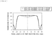
- FIG. 10 illustrates an example of a positional characteristic (here, characteristics exhibiting a relationship between the travel length d of the power receiving coil L2 and the transmission efficiency) change due to the presence of the auxiliary resonance section 3. It is found from this FIG. 10 that the transmission efficiency in a region in and above the power transmission coil L1 is improved, and substantially uniform transmission efficiency distribution is achieved (see arrows in the figure), by providing the auxiliary resonance section 3.
- a positional characteristic here, characteristics exhibiting a relationship between the travel length d of the power receiving coil L2 and the transmission efficiency
- the transmission efficiency distribution for the placement (the travel length d) of the power receiving coil L2 may be controlled optionally.
- f3 0.50 ⁇ f1
- the transmission efficiency relatively decreases in a region in and above the auxiliary coil L3
- the transmission efficiency relatively increases in a region in and above a gap between the auxiliary coil L3 and the power transmission coil L1. Therefore, electric power transmission in a selective region (here, the region in and above the gap between the auxiliary coil L3 and the power transmission coil L1) on the feeding surface S1 is achievable.
- the degree of such a positional characteristic change when the resonance frequency f3 is changed depends on the configuration and disposition of each of the power transmission coil L1 and the auxiliary coil L3, an influence of peripheral metal and peripheral magnetic material in the inside of a housing of the feed unit 1, an influence of metal and a magnetic material used for a housing of each of the electronic devices 2A and 2B, and the like. Therefore, a most suitable value may be set as the resonance frequency f3, in consideration of these influences. In other words, it can be said that the resonance frequency f3 may be set at a frequency so that the phase reversal and the considerable decline in the transmission efficiency described with reference to Part (A) and Part (B) of FIG. 9 do not occur in the vicinity of the resonance frequency f1 at the time of the electric power transmission.
- the following can be said about the positional characteristic change when the inner diameter ⁇ 3 of the auxiliary coil L3 is changed, or the positional characteristic change when the winding number n3 in the auxiliary coil L3 is changed. That is, it is found that the positional characteristics are allowed to be slightly changed by changing the inner diameter ⁇ 3 or the winding number n3 in the auxiliary coil L3. Specifically, a predetermined optimum value exists in the inner diameter ⁇ 3 of the auxiliary coil L3, and the transmission efficiency slightly decreases in the region in and above the auxiliary coil L3 when the inner diameter ⁇ 3 increases to be larger than the optimum value.
- a predetermined optimum value exists in the winding number n3 of the auxiliary coil L3, and the transmission efficiency slightly decreases in the region in and above the auxiliary coil L3 when the winding number n3 increases to be larger than the optimum value.
- the shape and disposition of the auxiliary coil L3, the resonance frequency f3, and the like are parameters in changing the positional characteristics (equalizing the transmission efficiency distribution), and it is found that, in particular, the resonance frequency f3 is an important parameter.
- the LC resonator in the auxiliary resonance section 3 includes the auxiliary coil L3 which is wound to form the gaps in at least a partial region.
- the resonance frequency f1 in the main resonance operation at the time of the electric power transmission using the magnetic field and the resonance frequency f3 in the LC resonator in the auxiliary resonance section 3 are made different from each other, the relationship (the positional characteristics) between the relative position between the power transmission side (the feed unit 1) and the power receiving side (the electronic devices 2A and 2B), and the transmission efficiency at the time of the electric power transmission is allowed to be changed, by adjusting the difference between those resonance frequencies f1 and f3. Therefore, when the electric power transmission (non-contact feeding) using a magnetic field is performed between the devices, it is possible to perform the transmission efficiency control according to the position of the device, in this case as well.
- the resonance frequency f3 is set to be higher than the resonance frequency f1 (f3 > f1), it is possible to reduce a variation of the transmission efficiency in response to the change of the relative position described above (nonuniformity of the transmission efficiency dependent on the relative position).
- planarization (equalization) of the transmission efficiency distribution according to the relative position is achievable, as compared with the case in which the resonance frequencies f1 and f3 are equal to each other (corresponding to the case of the comparative example 2). Therefore, it is possible to configure a non-contact feed system in which there is no dead band in a wide region on the feeding surface S 1 and in which substantially uniform transmission efficiency is obtainable. Further, this also makes it possible to obtain effects such as an improvement in feeding stability at the time of the non-contact feeding, an improvement in flexibility in placing the secondary-side device (the electronic devices 2A and 2B), and an improvement in capability of detecting dissimilar metal.
- the following effect is obtained when the inner diameter ⁇ 3 of the auxiliary coil L3 is made to be smaller than the inner diameter ⁇ 1 of the power transmission coil L1 ( ⁇ 3 ⁇ ⁇ 1). That is, it is possible to reinforce the magnetic field in the vicinity of the center of the power transmission coil L1, in which the magnetic field is relatively weak when the auxiliary coil L3 is not present, and the transmission efficiency distribution according to the relative position is allowed to be further equalized.
- FIG. 11 illustrates a configuration example (an X-Y plane configuration example) of a power transmission section (a power transmission section 110A) in a feed system according to a second embodiment.
- the power transmission coil L1 and the auxiliary coil L3 are disposed on the shield board 110S in a manner similar to that in the power transmission section 110 of the first embodiment, to be insulated (insulated physically and electrically) from each other.
- this power transmission section 110A includes the power transmission coil L1 and an auxiliary resonance section 3A, as with the power transmission section 110.
- this auxiliary resonance section 3A is provided with one LC resonator configured of one auxiliary coil L3 and one resonance capacitor C3, as with the auxiliary resonance section 3 of the first embodiment.
- the power transmission coil L1 and the auxiliary coil L3 each have an in-plane shape exhibiting anisotropy (for example, an oval shape, a rectangular shape, an elongated circular shape, or the like) (here, an elongated circular shape).
- a winding is provided to form a gap (a gap region) in at least a partial region, in the auxiliary coil L3 in the auxiliary resonance section 3A of the present embodiment as well, in a manner similar to that in the first embodiment.
- a plurality of gaps are formed from an outer edge side (an outer circumference side) towards an inner edge side (an inner circumference side) in the auxiliary coil L3.
- this auxiliary coil L3 is non-densely wound to continuously form the plurality of gaps G1 to G4 ranging from the inner edge to the outer edge thereof.
- widths (gap widths) of the respective gaps G1 to G4 gradually increase along a direction from the outer edge side towards the center of the auxiliary coil L3.
- these are set to satisfy a relation of (g4x > g3x > g2x > g1x) and (g4y > g3y > g2y > g1y), when the gap widths of the respective gaps G1 to G4 along a short direction (here, an X-axis direction) in the in-plane shape exhibiting anisotropy are assumed to be g1x, g2x, g3x, and g4x, and the gap widths of the respective gaps G1 to G4 along a longitudinal direction (here, an Y-axis direction) are assumed to be g1y, g2y, g3y, and g4y.
- these widths (the gap widths) of the respective gaps G1 to G4 in the longitudinal direction in the in-plane shape exhibiting anisotropy are larger than those in the short direction.
- these are set to satisfy a relation of (g1y > g1x), (g2y > g2x), (g3y > g3x), and (g4y > g4x). Setting in this way makes it possible to achieve equalization of the transmission efficiency distribution according to the relative position described above, more effectively.
- the configurations of the power transmission coil L1 and the auxiliary coil L3 in the power transmission section 110A are not limited to those illustrated in FIG. 11 either, and may have other configurations. In other words, for example, at least part of the above-described relations may be set so as not to be satisfied for each gap width.
- the resonance frequency f1 ( ⁇ f2) in main resonance operation at the time of electric power transmission using a magnetic field and the resonance frequency f3 in an LC resonator in the auxiliary resonance section 3A may be different from each other (f1 ⁇ f3), in the present embodiment as well.
- the resonance frequency f3 is a frequency that is higher than the resonance frequency f1 ( ⁇ f2) (f3 > f1).
- the resonance frequency f3 is a frequency that is lower than the resonance frequency f1 ( ⁇ f2) (f3 ⁇ f1).
- the LC resonator in the auxiliary resonance section 3A includes the auxiliary coil L3 which is wound to form the gaps in at least a partial region, in the feed system of the present embodiment as well. Therefore, similar effects by similar functions as those of the first embodiment are obtainable. In other words, when the electric power transmission (non-contact feeding) using a magnetic field is performed between the devices, transmission efficiency control according to the position of the device, and the like are allowed to be performed.
- auxiliary coil here, two auxiliary coils L31 and L32
- a power transmission section a power transmission section 401
- the following effects are obtained in the present embodiment as well. That is, the above-described effects are allowed to be obtained by providing only one auxiliary resonance section 3A.
- the number of components is allowed to be reduced as compared with the comparative example 4, making it possible to achieve a reduction in component cost and manufacturing cost, suppression of heat loss due to resistance in the components, and the like.
- FIG. 13 is a diagram illustrating data according to an Example of the present embodiment (an example of a positional characteristic change due to the presence or absence of the auxiliary resonance section 3A).
- FIG. 14 illustrates a schematic configuration example of a feed system (a feed system 4B) according to a third embodiment.
- the feed system 4B of the present embodiment is a system that performs non-contact electric power transmission using a magnetic field, as with the feed system 4.
- an electronic device to be fed (a secondary-side device) is larger than a feed unit (a primary-side device).
- a feed unit (a primary-side device)
- the feed system 4B includes the feed unit (not illustrated) having a power transmission unit 11B, and one or a plurality of electronic devices (not illustrated) each having a power receiving unit 21B.
- the power transmission unit 11B includes a power transmission section 110B having the power transmission coil L1
- the power receiving unit 21B includes a power receiving section 210B having the power receiving coil L2 and the auxiliary resonance section 3 (or the auxiliary resonance section 3A).
- this power receiving section 210B has one LC resonator configured of one auxiliary coil L3 and one resonance capacitor C3.
- the LC resonator in the auxiliary resonance section 3 or 3A includes the auxiliary coil L3 wound to form a gap in at least a partial region.
- the resonance frequency f2 ( ⁇ f1) at the time of main resonance operation in the power receiving unit 21B and the resonance frequency f3 in the LC resonator in the auxiliary resonance section 3 or 3A are different from each other (f2 ⁇ f3).
- the resonance frequency f3 may be a frequency higher than the resonance frequency f2 ( ⁇ f1) (f3 > f2).
- the resonance frequency f3 may be a frequency lower than the resonance frequency f2 ( ⁇ f1) (f3 ⁇ f2).
- the auxiliary resonance section 3 or 3A is provided and thus, similar effects by similar functions to those of each of the first and second embodiments are obtainable.
- the resonance frequency f3 is set to be a frequency higher than the resonance frequency f2 ( ⁇ f1), it is possible to reduce a variation of transmission efficiency in response to a change in a relative position (nonuniformity of the transmission efficiency dependent on the relative position).
- the auxiliary resonance section 3 or 3A is provided on the power receiving unit 21B side (the electronic device side).
- the auxiliary resonance section 3 or 3A is provided on the power receiving unit 21B side (the electronic device side).
- the auxiliary resonance section 3 or 3A is not provided on an power receiving unit 502 side having a power receiving section 502A (on an electronic device side), the nonuniformity of the transmission efficiency depending on the placement position of the feed unit in the power receiving surface of the electronic device is allowed to be reduced.
- FIG. 16 illustrates a schematic configuration example of a feed system (a feed system 4C) according to a fourth embodiment.
- the feed system 4C of the present embodiment is a system that performs non-contact electric power transmission using a magnetic field, as with the feed system 4.
- the present embodiment corresponds to a case in which a power transmission surface (a feeding surface) and a power receiving surface that are relatively large are provided on both a feed unit (a primary-side device) and an electronic device (a secondary-side device).
- the feed system 4C includes a feed unit (not illustrated) having a power transmission unit 11, and one or a plurality of electronic devices (not illustrated) each having a power receiving unit 21B.
- the power transmission unit 11 includes a power transmission section 110 (or a power transmission section 110A) having the power transmission coil L1 and the auxiliary resonance section 3 (or the auxiliary resonance section 3A), and the power receiving unit 21B includes a power receiving section 210B having the power receiving coil L2 and the auxiliary resonance section 3 (or the auxiliary resonance section 3A).
- both the power transmission unit 11 and the power receiving unit 21B include the respective auxiliary resonance sections 3 (or the auxiliary resonance sections 3A) each having one LC resonator configured of one auxiliary coil L3 and one resonance capacitor C3.
- auxiliary resonance sections 3 and 3A in the present embodiment are basically similar to those described in the first to third embodiments.
- the auxiliary resonance section 3 or 3A is provided and thus, it is possible to obtain similar effects by similar functions to those of each of the first to third embodiments.
- the resonance frequency f3 is set to be a frequency higher than the resonance frequencies f1 and f2
- the auxiliary resonance section 3 or 3A is provided on both the power transmission unit (the feed unit) side and the power receiving unit (the electronic device) side.
- the nonuniformity of the transmission efficiency which depends on the placement position of the electronic device in the power transmission surface (the feeding surface) of the feed unit, as well as the placement position of the feed unit in the power receiving surface of the electronic device (the relative position).
- Part (A) and Part (B) of FIG. 17 each illustrate a schematic configuration example of a feed system (each of feed systems 4D and 4E) according to a fifth embodiment.
- Each of the feed systems 4D and 4E of the present embodiment is a system that performs non-contact electric power transmission using a magnetic field, as with the feed system 4.
- the auxiliary resonance section 3 or the auxiliary resonance section 3A is provided in other unit (an auxiliary unit 41 that will be described later) independent of a feed unit (a primary-side device) and an electronic device (a secondary-side device).
- the feed systems of the present embodiment each include the feed unit, one or a plurality of electronic devices, and the auxiliary unit having an auxiliary resonance section.
- the feed system 4D illustrated in Part (A) of FIG. 17 includes the feed unit (not illustrated) having a power transmission unit 11D, one or a plurality of electronic devices (not illustrated) each having a power receiving unit 21, and the auxiliary unit 41 having the auxiliary resonance section 3 or the auxiliary resonance section 3A.
- the power transmission unit 11D includes a power transmission section 110D having the power transmission coil L1
- the power receiving unit 21 includes a power receiving section 210 having the power receiving coil L2.
- the auxiliary unit 41 independent of the feed unit (the power transmission unit 11D) and the electronic device (the power receiving unit 21) includes the auxiliary resonance section 3 or the auxiliary resonance section 3A having one LC resonator configured of one auxiliary coil L3 and one resonance capacitor C3.
- the power transmission unit 11D and the power transmission section 110D have configurations similar to those of the power transmission unit 101 and the power transmission section 101A described above, respectively.
- the feed system 4E illustrated in Part (B) of FIG. 17 includes the feed unit (not illustrated) having a power transmission unit 11B, one or a plurality of electronic devices (not illustrated) each having a power receiving unit 21E, and the auxiliary unit 41 having the auxiliary resonance section 3 or the auxiliary resonance section 3A. Further, the power transmission unit 11B includes the power transmission section 110B having the power transmission coil L1, and the power receiving unit 21E includes a power receiving section 210E having the power receiving coil L2.
- the auxiliary unit 41 independent of the feed unit (the power transmission unit 11B) and the electronic device (the power receiving unit 21E) includes the auxiliary resonance section 3 or the auxiliary resonance section 3A having one LC resonator configured of one auxiliary coil L3 and one resonance capacitor C3. It is to be noted that the power receiving unit 21E and the power receiving section 210E have configurations similar to those of the power receiving unit 502 and the power receiving section 502A described above, respectively.
- the auxiliary resonance section 3 or 3A is provided and thus, it is possible to obtain similar effects by similar functions to those of each of the first to fourth embodiments.
- the resonance frequency f3 is set to be a frequency higher than the resonance frequencies f1 and f2
- the auxiliary resonance section 3 or the auxiliary resonance section 3A is provided in other unit (the auxiliary unit 41) independent of the power transmission unit and the electronic device.
- the auxiliary unit 41 independent of the power transmission unit and the electronic device.
- each coil (the power transmission coil, the power receiving coil, and the auxiliary coil) is assumed to have a spiral shape (a planar shape), but each coil may be configured to have, for example, an ⁇ -winding shape in which a spiral coil is folded to be in two layers, a spiral shape having more multiple layers, a helical shape in which a winding is wound in a thickness direction, etc.
- each coil may be not only a winding coil configured using a wire rod having conductivity, but also a pattern coil having conductivity and configured using a printed circuit board, a flexible printed circuit board, etc. It is to be noted that, in place of the auxiliary coil having a coil shape, a conductive loop having a loop shape may be used to configure the LC resonator.
- each of the resonance capacitors is not limited to the case of using a fixed electrostatic capacitance value, and may have a configuration in which an electrostatic capacitance value is allowed to be variable (for example, a configuration of switching between connection paths of a plurality of capacitors).
- control (optimization) of a resonance frequency is allowed to be performed by adjusting the electrostatic capacitance value.
- auxiliary resonance section described above in each of the above-described embodiments and the like may be provided in at least one of the feed unit, the electronic device, the other unit independent of the feed unit and the electronic device.
- each component of the feed unit, the electronic device, and the like has been specifically described, but it is not necessary to provide all the components, or other components may be further provided.
- a communication function a function of performing some kind of control, a display function, a function of authenticating a secondary-side device, a function of detecting the secondary-side device being on the primary-side device, a function of detecting a mixture such as dissimilar metal, and/or the like may be provided in the feed unit and/or the electronic device.
- the charging tray for the small electronic device such as a mobile phone
- the feed unit is not limited to such a home charging tray, and may be applicable to battery chargers of various kinds of electronic devices.
- the feed unit it is not necessarily for the feed unit to be a tray, and may be, for example, a stand for an electronic device such as a so-called cradle.
Applications Claiming Priority (3)
| Application Number | Priority Date | Filing Date | Title |
|---|---|---|---|
| JP2011112349A JP2012244763A (ja) | 2011-05-19 | 2011-05-19 | 給電装置、給電システムおよび電子機器 |
| EP12784991.7A EP2711946B1 (fr) | 2011-05-19 | 2012-05-07 | Dispositif d'alimentation électrique et système d'alimentation électrique |
| PCT/JP2012/061645 WO2012157454A1 (fr) | 2011-05-19 | 2012-05-07 | Dispositif d'alimentation électrique, système d'alimentation électrique et dispositif électronique |
Related Parent Applications (2)
| Application Number | Title | Priority Date | Filing Date |
|---|---|---|---|
| EP12784991.7A Division EP2711946B1 (fr) | 2011-05-19 | 2012-05-07 | Dispositif d'alimentation électrique et système d'alimentation électrique |
| EP12784991.7A Division-Into EP2711946B1 (fr) | 2011-05-19 | 2012-05-07 | Dispositif d'alimentation électrique et système d'alimentation électrique |
Publications (2)
| Publication Number | Publication Date |
|---|---|
| EP3471117A1 true EP3471117A1 (fr) | 2019-04-17 |
| EP3471117B1 EP3471117B1 (fr) | 2020-06-24 |
Family
ID=47176788
Family Applications (2)
| Application Number | Title | Priority Date | Filing Date |
|---|---|---|---|
| EP12784991.7A Not-in-force EP2711946B1 (fr) | 2011-05-19 | 2012-05-07 | Dispositif d'alimentation électrique et système d'alimentation électrique |
| EP18205975.8A Active EP3471117B1 (fr) | 2011-05-19 | 2012-05-07 | Unité d'alimentation et système d'alimentation |
Family Applications Before (1)
| Application Number | Title | Priority Date | Filing Date |
|---|---|---|---|
| EP12784991.7A Not-in-force EP2711946B1 (fr) | 2011-05-19 | 2012-05-07 | Dispositif d'alimentation électrique et système d'alimentation électrique |
Country Status (5)
| Country | Link |
|---|---|
| US (1) | US10340077B2 (fr) |
| EP (2) | EP2711946B1 (fr) |
| JP (1) | JP2012244763A (fr) |
| CN (1) | CN103534772B (fr) |
| WO (1) | WO2012157454A1 (fr) |
Families Citing this family (41)
| Publication number | Priority date | Publication date | Assignee | Title |
|---|---|---|---|---|
| JP6089330B2 (ja) * | 2012-08-10 | 2017-03-08 | パナソニックIpマネジメント株式会社 | 小型電気機器およびこれを有する非接触式電力伝送装置 |
| US9362776B2 (en) * | 2012-11-27 | 2016-06-07 | Qualcomm Incorporated | Wireless charging systems and methods |
| JP2014138509A (ja) * | 2013-01-17 | 2014-07-28 | Ngk Spark Plug Co Ltd | 共振器及び無線給電システム |
| US20140265617A1 (en) * | 2013-03-15 | 2014-09-18 | Witricity Corporation | Wireless energy transfer |
| JP6201380B2 (ja) | 2013-04-03 | 2017-09-27 | 船井電機株式会社 | 非接触通信コイル、非接触給電装置、及び非接触受電装置 |
| US9640318B2 (en) | 2013-12-07 | 2017-05-02 | Intel Corporation | Non-uniform spacing in wireless resonator coil |
| CN104701995B (zh) * | 2013-12-07 | 2019-03-29 | 英特尔公司 | 无线谐振器线圈中的非均匀间距 |
| JP6315382B2 (ja) * | 2013-12-19 | 2018-04-25 | パナソニックIpマネジメント株式会社 | 無線電力伝送のための送電装置および受電装置ならびに無線電力伝送システム |
| US9685792B2 (en) * | 2014-03-05 | 2017-06-20 | Intel Corporation | Magnetic field distrubtion in wireless power |
| WO2015161053A1 (fr) | 2014-04-16 | 2015-10-22 | Witricity Corporation | Transfert d'énergie sans fil pour applications de dispositif mobile |
| CN107210126A (zh) * | 2014-09-11 | 2017-09-26 | 奥克兰联合服务有限公司 | 具有受控磁通抵消的磁通耦合结构 |
| KR20160038315A (ko) * | 2014-09-30 | 2016-04-07 | 엘지이노텍 주식회사 | 무선 전력 송신 장치 |
| KR101535048B1 (ko) | 2014-09-30 | 2015-07-09 | 엘지이노텍 주식회사 | 무선 전력 송신 장치 |
| WO2016121055A1 (fr) * | 2015-01-29 | 2016-08-04 | 日産自動車株式会社 | Structure de bobine de transmission de puissance dans un dispositif de transmission de puissance sans contact |
| EP3282554B1 (fr) * | 2015-04-07 | 2019-01-09 | Nissan Motor Co., Ltd. | Dispositif d'estimation de température et procédé d'estimation de température pour dispositif de réception de puissance sans contact |
| JP6376284B2 (ja) * | 2015-04-08 | 2018-08-22 | 日産自動車株式会社 | 地上側コイルユニット |
| US10511191B2 (en) | 2015-07-09 | 2019-12-17 | Qualcomm Incorporated | Apparatus and methods for wireless power transmitter coil configuration |
| JP2017050992A (ja) * | 2015-09-02 | 2017-03-09 | 株式会社日本自動車部品総合研究所 | 無線給電装置の送電ユニット |
| KR101939663B1 (ko) * | 2015-10-30 | 2019-01-17 | 주식회사 아모센스 | 무선충전용 자기장 차폐시트 및 이를 포함하는 무선전력 수신모듈 |
| US10714960B2 (en) * | 2015-12-22 | 2020-07-14 | Intel Corporation | Uniform wireless charging device |
| USD814432S1 (en) | 2016-02-09 | 2018-04-03 | Witricity Corporation | Resonator coil |
| JP6522546B2 (ja) | 2016-05-12 | 2019-05-29 | マクセル株式会社 | 電力コイル |
| US10530175B2 (en) * | 2016-08-09 | 2020-01-07 | Taiwan Semiconductor Manufacturing Company, Ltd. | Hexagonal semiconductor package structure |
| US20190207432A1 (en) * | 2016-09-28 | 2019-07-04 | Nidec Corporation | Contactless power supply coil unit |
| KR102063674B1 (ko) * | 2016-12-20 | 2020-01-08 | 주식회사 아모텍 | 무선 전력 전송 안테나 |
| KR102076127B1 (ko) * | 2016-12-20 | 2020-02-11 | 주식회사 아모텍 | 무선 전력 전송 안테나 |
| CN206650505U (zh) * | 2017-01-23 | 2017-11-17 | 王丽 | 无线充电接收侧电感模组、接收装置、电子设备及保护套 |
| US11277030B2 (en) | 2017-03-07 | 2022-03-15 | Powermat Technologies Ltd. | System for wireless power charging |
| US11218025B2 (en) * | 2017-03-07 | 2022-01-04 | Powermat Technologies Ltd. | System for wireless power charging |
| US11282638B2 (en) | 2017-05-26 | 2022-03-22 | Nucurrent, Inc. | Inductor coil structures to influence wireless transmission performance |
| CN107749675A (zh) * | 2017-10-26 | 2018-03-02 | 武汉慧驰科技有限公司 | 基于磁谐振耦合的无线电能传输系统 |
| TWI645648B (zh) * | 2018-04-03 | 2018-12-21 | 群光電能科技股份有限公司 | 充電裝置與應用於充電裝置之適應性分頻控制方法 |
| JP7196436B2 (ja) * | 2018-06-28 | 2022-12-27 | 大日本印刷株式会社 | コイル対、送電装置及び受電装置並びに電力伝送システム |
| CN111200318A (zh) * | 2018-11-19 | 2020-05-26 | 无锡华润矽科微电子有限公司 | 无线电能传输装置 |
| JP7283127B2 (ja) * | 2019-02-27 | 2023-05-30 | Tdk株式会社 | コイル部品 |
| CN111835043A (zh) * | 2019-04-16 | 2020-10-27 | 致伸科技股份有限公司 | 无线充电装置及其发射端模块与发射端线圈 |
| CN116056318A (zh) * | 2020-03-27 | 2023-05-02 | 住友电气工业株式会社 | 柔性印刷布线板 |
| US11283303B2 (en) | 2020-07-24 | 2022-03-22 | Nucurrent, Inc. | Area-apportioned wireless power antenna for maximized charging volume |
| US11695302B2 (en) | 2021-02-01 | 2023-07-04 | Nucurrent, Inc. | Segmented shielding for wide area wireless power transmitter |
| US11527912B2 (en) * | 2021-02-01 | 2022-12-13 | Nucurrent, Inc. | Shaped coil for wireless power transmission system coupling |
| CN114221450A (zh) * | 2021-12-22 | 2022-03-22 | 宁波微鹅电子科技有限公司 | 一种无线充电附加装置、无线电能发射以及接收装置 |
Citations (5)
| Publication number | Priority date | Publication date | Assignee | Title |
|---|---|---|---|---|
| WO2008044875A1 (fr) * | 2006-10-10 | 2008-04-17 | Ls Cable, Ltd. | Alimentation rechargeable, dispositif de batterie, systèmes de charge sans contact et procédé de charge de cellule de batterie rechargeable |
| JP2008136311A (ja) | 2006-11-29 | 2008-06-12 | Asuka Electron Kk | 複合平面コイル |
| JP2009504115A (ja) | 2005-07-27 | 2009-01-29 | エルエス ケーブル リミテッド | 充電効率のバラツキが改善された無線充電器 |
| US20100244579A1 (en) * | 2009-03-26 | 2010-09-30 | Seiko Epson Corporation | Coil unit, and power transmission device and power reception device using the coil unit |
| WO2011036863A1 (fr) * | 2009-09-24 | 2011-03-31 | パナソニック電工株式会社 | Système chargeur sans contact |
Family Cites Families (14)
| Publication number | Priority date | Publication date | Assignee | Title |
|---|---|---|---|---|
| JP3755453B2 (ja) * | 2001-11-26 | 2006-03-15 | 株式会社村田製作所 | インダクタ部品およびそのインダクタンス値調整方法 |
| KR20040072581A (ko) * | 2004-07-29 | 2004-08-18 | (주)제이씨 프로텍 | 전자기파 증폭중계기 및 이를 이용한 무선전력변환장치 |
| US8369659B2 (en) * | 2006-03-22 | 2013-02-05 | The Invention Science Fund I Llc | High-Q resonators assembly |
| JP2009118587A (ja) * | 2007-11-02 | 2009-05-28 | Meleagros Corp | 電力伝送装置 |
| US7960867B2 (en) * | 2007-11-27 | 2011-06-14 | Extremely Ingenious Engineering | Methods and systems for wireless energy and data transmission |
| TWI563766B (en) * | 2008-03-13 | 2016-12-21 | Access Business Group Int Llc | Inductive power supply system with multiple coil primary and inductive power supply and method for the same |
| JP4911148B2 (ja) * | 2008-09-02 | 2012-04-04 | ソニー株式会社 | 非接触給電装置 |
| JP5353376B2 (ja) * | 2009-03-31 | 2013-11-27 | 富士通株式会社 | 無線電力装置、無線電力受信方法 |
| DE102009026148A1 (de) * | 2009-07-10 | 2011-01-13 | Saint-Gobain Sekurit Deutschland Gmbh & Co. Kg | Elektrochrome Schichtstruktur und Verfahren zu dessen Herstellung |
| JP5476917B2 (ja) * | 2009-10-16 | 2014-04-23 | Tdk株式会社 | ワイヤレス給電装置、ワイヤレス受電装置およびワイヤレス電力伝送システム |
| KR101659080B1 (ko) * | 2009-11-13 | 2016-09-23 | 삼성전자주식회사 | 충전 제어를 위한 무선 충전기 및 방법 |
| JP2011142724A (ja) * | 2010-01-06 | 2011-07-21 | Hitachi Ltd | 非接触電力伝送装置及びそのための近接場アンテナ |
| JP2011147271A (ja) * | 2010-01-14 | 2011-07-28 | Sony Corp | 給電装置、受電装置、およびワイヤレス給電システム |
| JP2011205757A (ja) * | 2010-03-25 | 2011-10-13 | Toyota Central R&D Labs Inc | 電磁界共鳴電力伝送装置 |
-
2011
- 2011-05-19 JP JP2011112349A patent/JP2012244763A/ja not_active Withdrawn
-
2012
- 2012-05-07 EP EP12784991.7A patent/EP2711946B1/fr not_active Not-in-force
- 2012-05-07 WO PCT/JP2012/061645 patent/WO2012157454A1/fr active Application Filing
- 2012-05-07 EP EP18205975.8A patent/EP3471117B1/fr active Active
- 2012-05-07 US US14/116,055 patent/US10340077B2/en active Active
- 2012-05-07 CN CN201280022908.1A patent/CN103534772B/zh not_active Expired - Fee Related
Patent Citations (6)
| Publication number | Priority date | Publication date | Assignee | Title |
|---|---|---|---|---|
| JP2009504115A (ja) | 2005-07-27 | 2009-01-29 | エルエス ケーブル リミテッド | 充電効率のバラツキが改善された無線充電器 |
| WO2008044875A1 (fr) * | 2006-10-10 | 2008-04-17 | Ls Cable, Ltd. | Alimentation rechargeable, dispositif de batterie, systèmes de charge sans contact et procédé de charge de cellule de batterie rechargeable |
| JP2008136311A (ja) | 2006-11-29 | 2008-06-12 | Asuka Electron Kk | 複合平面コイル |
| US20100244579A1 (en) * | 2009-03-26 | 2010-09-30 | Seiko Epson Corporation | Coil unit, and power transmission device and power reception device using the coil unit |
| WO2011036863A1 (fr) * | 2009-09-24 | 2011-03-31 | パナソニック電工株式会社 | Système chargeur sans contact |
| US20120146580A1 (en) * | 2009-09-24 | 2012-06-14 | Panasonic Corporation | Noncontact charger system |
Also Published As
| Publication number | Publication date |
|---|---|
| EP2711946A4 (fr) | 2014-11-19 |
| CN103534772A (zh) | 2014-01-22 |
| EP3471117B1 (fr) | 2020-06-24 |
| CN103534772B (zh) | 2016-12-07 |
| US20150170830A1 (en) | 2015-06-18 |
| WO2012157454A1 (fr) | 2012-11-22 |
| US10340077B2 (en) | 2019-07-02 |
| EP2711946B1 (fr) | 2019-02-20 |
| JP2012244763A (ja) | 2012-12-10 |
| EP2711946A1 (fr) | 2014-03-26 |
Similar Documents
| Publication | Publication Date | Title |
|---|---|---|
| EP3471117B1 (fr) | Unité d'alimentation et système d'alimentation | |
| JP6264437B2 (ja) | 給電装置、給電システムおよび電子機器 | |
| JP5968596B2 (ja) | 無線電力供給システム | |
| JP5405694B1 (ja) | 送電装置、電子機器およびワイヤレス電力伝送システム | |
| EP2760035B1 (fr) | Procédé de formation d'espace de champ magnétique | |
| US10516300B2 (en) | Power receiving unit, power receiving control method, feed system, and electronic apparatus | |
| US9570935B2 (en) | Magnetic coupling unit and magnetic coupling system | |
| JP6199058B2 (ja) | 無線電力伝送によって電力供給される被給電機器の受電電圧制御方法、当該受電電圧制御方法によって調整された無線電力伝送装置、及び、その無線電力伝送装置の製造方法 | |
| WO2014199830A1 (fr) | Dispositif de transmission d'énergie sans fil et procédé d'alimentation électrique de dispositif de transmission d'énergie sans fil | |
| WO2015108030A1 (fr) | Dispositif de transmission d'énergie électrique sans fil et son procédé de fabrication | |
| WO2014199827A1 (fr) | Module d'alimentation en électricité utilisant une transmission électrique sans fil et procédé d'alimentation électrique pour module d'alimentation en électricité | |
| WO2014132480A1 (fr) | Dispositif de transmission d'énergie sans fil, procédé d'ajustement de réponse de fluctuation de charge d'impédance d'entrée dans le dispositif de transmission d'énergie sans fil et procédé de fabrication du dispositif de transmission d'énergie sans fil | |
| JP5981203B2 (ja) | 電力伝送システム | |
| US20180269718A1 (en) | Wireless power transfer systems and methods using non-resonant power receiver | |
| JP2015213428A (ja) | 無線電力供給システム |
Legal Events
| Date | Code | Title | Description |
|---|---|---|---|
| PUAI | Public reference made under article 153(3) epc to a published international application that has entered the european phase |
Free format text: ORIGINAL CODE: 0009012 |
|
| STAA | Information on the status of an ep patent application or granted ep patent |
Free format text: STATUS: REQUEST FOR EXAMINATION WAS MADE |
|
| 17P | Request for examination filed |
Effective date: 20181113 |
|
| AC | Divisional application: reference to earlier application |
Ref document number: 2711946 Country of ref document: EP Kind code of ref document: P |
|
| AK | Designated contracting states |
Kind code of ref document: A1 Designated state(s): AL AT BE BG CH CY CZ DE DK EE ES FI FR GB GR HR HU IE IS IT LI LT LU LV MC MK MT NL NO PL PT RO RS SE SI SK SM TR |
|
| GRAP | Despatch of communication of intention to grant a patent |
Free format text: ORIGINAL CODE: EPIDOSNIGR1 |
|
| STAA | Information on the status of an ep patent application or granted ep patent |
Free format text: STATUS: GRANT OF PATENT IS INTENDED |
|
| INTG | Intention to grant announced |
Effective date: 20200120 |
|
| GRAS | Grant fee paid |
Free format text: ORIGINAL CODE: EPIDOSNIGR3 |
|
| GRAA | (expected) grant |
Free format text: ORIGINAL CODE: 0009210 |
|
| STAA | Information on the status of an ep patent application or granted ep patent |
Free format text: STATUS: THE PATENT HAS BEEN GRANTED |
|
| AC | Divisional application: reference to earlier application |
Ref document number: 2711946 Country of ref document: EP Kind code of ref document: P |
|
| AK | Designated contracting states |
Kind code of ref document: B1 Designated state(s): AL AT BE BG CH CY CZ DE DK EE ES FI FR GB GR HR HU IE IS IT LI LT LU LV MC MK MT NL NO PL PT RO RS SE SI SK SM TR |
|
| REG | Reference to a national code |
Ref country code: GB Ref legal event code: FG4D |
|
| REG | Reference to a national code |
Ref country code: CH Ref legal event code: EP |
|
| REG | Reference to a national code |
Ref country code: AT Ref legal event code: REF Ref document number: 1284723 Country of ref document: AT Kind code of ref document: T Effective date: 20200715 |
|
| REG | Reference to a national code |
Ref country code: DE Ref legal event code: R096 Ref document number: 602012070975 Country of ref document: DE |
|
| REG | Reference to a national code |
Ref country code: IE Ref legal event code: FG4D |
|
| PG25 | Lapsed in a contracting state [announced via postgrant information from national office to epo] |
Ref country code: FI Free format text: LAPSE BECAUSE OF FAILURE TO SUBMIT A TRANSLATION OF THE DESCRIPTION OR TO PAY THE FEE WITHIN THE PRESCRIBED TIME-LIMIT Effective date: 20200624 Ref country code: LT Free format text: LAPSE BECAUSE OF FAILURE TO SUBMIT A TRANSLATION OF THE DESCRIPTION OR TO PAY THE FEE WITHIN THE PRESCRIBED TIME-LIMIT Effective date: 20200624 Ref country code: SE Free format text: LAPSE BECAUSE OF FAILURE TO SUBMIT A TRANSLATION OF THE DESCRIPTION OR TO PAY THE FEE WITHIN THE PRESCRIBED TIME-LIMIT Effective date: 20200624 Ref country code: GR Free format text: LAPSE BECAUSE OF FAILURE TO SUBMIT A TRANSLATION OF THE DESCRIPTION OR TO PAY THE FEE WITHIN THE PRESCRIBED TIME-LIMIT Effective date: 20200925 Ref country code: NO Free format text: LAPSE BECAUSE OF FAILURE TO SUBMIT A TRANSLATION OF THE DESCRIPTION OR TO PAY THE FEE WITHIN THE PRESCRIBED TIME-LIMIT Effective date: 20200924 |
|
| REG | Reference to a national code |
Ref country code: LT Ref legal event code: MG4D |
|
| PG25 | Lapsed in a contracting state [announced via postgrant information from national office to epo] |
Ref country code: RS Free format text: LAPSE BECAUSE OF FAILURE TO SUBMIT A TRANSLATION OF THE DESCRIPTION OR TO PAY THE FEE WITHIN THE PRESCRIBED TIME-LIMIT Effective date: 20200624 Ref country code: HR Free format text: LAPSE BECAUSE OF FAILURE TO SUBMIT A TRANSLATION OF THE DESCRIPTION OR TO PAY THE FEE WITHIN THE PRESCRIBED TIME-LIMIT Effective date: 20200624 Ref country code: BG Free format text: LAPSE BECAUSE OF FAILURE TO SUBMIT A TRANSLATION OF THE DESCRIPTION OR TO PAY THE FEE WITHIN THE PRESCRIBED TIME-LIMIT Effective date: 20200924 Ref country code: LV Free format text: LAPSE BECAUSE OF FAILURE TO SUBMIT A TRANSLATION OF THE DESCRIPTION OR TO PAY THE FEE WITHIN THE PRESCRIBED TIME-LIMIT Effective date: 20200624 |
|
| REG | Reference to a national code |
Ref country code: NL Ref legal event code: MP Effective date: 20200624 |
|
| REG | Reference to a national code |
Ref country code: AT Ref legal event code: MK05 Ref document number: 1284723 Country of ref document: AT Kind code of ref document: T Effective date: 20200624 |
|
| PG25 | Lapsed in a contracting state [announced via postgrant information from national office to epo] |
Ref country code: AL Free format text: LAPSE BECAUSE OF FAILURE TO SUBMIT A TRANSLATION OF THE DESCRIPTION OR TO PAY THE FEE WITHIN THE PRESCRIBED TIME-LIMIT Effective date: 20200624 Ref country code: NL Free format text: LAPSE BECAUSE OF FAILURE TO SUBMIT A TRANSLATION OF THE DESCRIPTION OR TO PAY THE FEE WITHIN THE PRESCRIBED TIME-LIMIT Effective date: 20200624 |
|
| PG25 | Lapsed in a contracting state [announced via postgrant information from national office to epo] |
Ref country code: PT Free format text: LAPSE BECAUSE OF FAILURE TO SUBMIT A TRANSLATION OF THE DESCRIPTION OR TO PAY THE FEE WITHIN THE PRESCRIBED TIME-LIMIT Effective date: 20201026 Ref country code: ES Free format text: LAPSE BECAUSE OF FAILURE TO SUBMIT A TRANSLATION OF THE DESCRIPTION OR TO PAY THE FEE WITHIN THE PRESCRIBED TIME-LIMIT Effective date: 20200624 Ref country code: RO Free format text: LAPSE BECAUSE OF FAILURE TO SUBMIT A TRANSLATION OF THE DESCRIPTION OR TO PAY THE FEE WITHIN THE PRESCRIBED TIME-LIMIT Effective date: 20200624 Ref country code: IT Free format text: LAPSE BECAUSE OF FAILURE TO SUBMIT A TRANSLATION OF THE DESCRIPTION OR TO PAY THE FEE WITHIN THE PRESCRIBED TIME-LIMIT Effective date: 20200624 Ref country code: AT Free format text: LAPSE BECAUSE OF FAILURE TO SUBMIT A TRANSLATION OF THE DESCRIPTION OR TO PAY THE FEE WITHIN THE PRESCRIBED TIME-LIMIT Effective date: 20200624 Ref country code: CZ Free format text: LAPSE BECAUSE OF FAILURE TO SUBMIT A TRANSLATION OF THE DESCRIPTION OR TO PAY THE FEE WITHIN THE PRESCRIBED TIME-LIMIT Effective date: 20200624 Ref country code: EE Free format text: LAPSE BECAUSE OF FAILURE TO SUBMIT A TRANSLATION OF THE DESCRIPTION OR TO PAY THE FEE WITHIN THE PRESCRIBED TIME-LIMIT Effective date: 20200624 Ref country code: SM Free format text: LAPSE BECAUSE OF FAILURE TO SUBMIT A TRANSLATION OF THE DESCRIPTION OR TO PAY THE FEE WITHIN THE PRESCRIBED TIME-LIMIT Effective date: 20200624 |
|
| PG25 | Lapsed in a contracting state [announced via postgrant information from national office to epo] |
Ref country code: SK Free format text: LAPSE BECAUSE OF FAILURE TO SUBMIT A TRANSLATION OF THE DESCRIPTION OR TO PAY THE FEE WITHIN THE PRESCRIBED TIME-LIMIT Effective date: 20200624 Ref country code: PL Free format text: LAPSE BECAUSE OF FAILURE TO SUBMIT A TRANSLATION OF THE DESCRIPTION OR TO PAY THE FEE WITHIN THE PRESCRIBED TIME-LIMIT Effective date: 20200624 Ref country code: IS Free format text: LAPSE BECAUSE OF FAILURE TO SUBMIT A TRANSLATION OF THE DESCRIPTION OR TO PAY THE FEE WITHIN THE PRESCRIBED TIME-LIMIT Effective date: 20201024 |
|
| REG | Reference to a national code |
Ref country code: DE Ref legal event code: R097 Ref document number: 602012070975 Country of ref document: DE |
|
| PG25 | Lapsed in a contracting state [announced via postgrant information from national office to epo] |
Ref country code: DK Free format text: LAPSE BECAUSE OF FAILURE TO SUBMIT A TRANSLATION OF THE DESCRIPTION OR TO PAY THE FEE WITHIN THE PRESCRIBED TIME-LIMIT Effective date: 20200624 |
|
| PLBE | No opposition filed within time limit |
Free format text: ORIGINAL CODE: 0009261 |
|
| STAA | Information on the status of an ep patent application or granted ep patent |
Free format text: STATUS: NO OPPOSITION FILED WITHIN TIME LIMIT |
|
| 26N | No opposition filed |
Effective date: 20210325 |
|
| PG25 | Lapsed in a contracting state [announced via postgrant information from national office to epo] |
Ref country code: SI Free format text: LAPSE BECAUSE OF FAILURE TO SUBMIT A TRANSLATION OF THE DESCRIPTION OR TO PAY THE FEE WITHIN THE PRESCRIBED TIME-LIMIT Effective date: 20200624 |
|
| REG | Reference to a national code |
Ref country code: CH Ref legal event code: PL |
|
| GBPC | Gb: european patent ceased through non-payment of renewal fee |
Effective date: 20210507 |
|
| PG25 | Lapsed in a contracting state [announced via postgrant information from national office to epo] |
Ref country code: CH Free format text: LAPSE BECAUSE OF NON-PAYMENT OF DUE FEES Effective date: 20210531 Ref country code: MC Free format text: LAPSE BECAUSE OF FAILURE TO SUBMIT A TRANSLATION OF THE DESCRIPTION OR TO PAY THE FEE WITHIN THE PRESCRIBED TIME-LIMIT Effective date: 20200624 Ref country code: LU Free format text: LAPSE BECAUSE OF NON-PAYMENT OF DUE FEES Effective date: 20210507 Ref country code: LI Free format text: LAPSE BECAUSE OF NON-PAYMENT OF DUE FEES Effective date: 20210531 |
|
| REG | Reference to a national code |
Ref country code: BE Ref legal event code: MM Effective date: 20210531 |
|
| PG25 | Lapsed in a contracting state [announced via postgrant information from national office to epo] |
Ref country code: IE Free format text: LAPSE BECAUSE OF NON-PAYMENT OF DUE FEES Effective date: 20210507 Ref country code: GB Free format text: LAPSE BECAUSE OF NON-PAYMENT OF DUE FEES Effective date: 20210507 |
|
| PG25 | Lapsed in a contracting state [announced via postgrant information from national office to epo] |
Ref country code: FR Free format text: LAPSE BECAUSE OF NON-PAYMENT OF DUE FEES Effective date: 20210531 |
|
| PG25 | Lapsed in a contracting state [announced via postgrant information from national office to epo] |
Ref country code: BE Free format text: LAPSE BECAUSE OF NON-PAYMENT OF DUE FEES Effective date: 20210531 |
|
| PGFP | Annual fee paid to national office [announced via postgrant information from national office to epo] |
Ref country code: DE Payment date: 20220420 Year of fee payment: 11 |
|
| PG25 | Lapsed in a contracting state [announced via postgrant information from national office to epo] |
Ref country code: CY Free format text: LAPSE BECAUSE OF FAILURE TO SUBMIT A TRANSLATION OF THE DESCRIPTION OR TO PAY THE FEE WITHIN THE PRESCRIBED TIME-LIMIT Effective date: 20200624 |
|
| P01 | Opt-out of the competence of the unified patent court (upc) registered |
Effective date: 20230528 |
|
| PG25 | Lapsed in a contracting state [announced via postgrant information from national office to epo] |
Ref country code: HU Free format text: LAPSE BECAUSE OF FAILURE TO SUBMIT A TRANSLATION OF THE DESCRIPTION OR TO PAY THE FEE WITHIN THE PRESCRIBED TIME-LIMIT; INVALID AB INITIO Effective date: 20120507 |
|
| REG | Reference to a national code |
Ref country code: DE Ref legal event code: R119 Ref document number: 602012070975 Country of ref document: DE |
|
| PG25 | Lapsed in a contracting state [announced via postgrant information from national office to epo] |
Ref country code: MK Free format text: LAPSE BECAUSE OF FAILURE TO SUBMIT A TRANSLATION OF THE DESCRIPTION OR TO PAY THE FEE WITHIN THE PRESCRIBED TIME-LIMIT Effective date: 20200624 Ref country code: DE Free format text: LAPSE BECAUSE OF NON-PAYMENT OF DUE FEES Effective date: 20231201 |