EP3470321B1 - Körper für eine fahrradhinterradnabe und mit solch einem körper an der nabe montierbare kassette - Google Patents
Körper für eine fahrradhinterradnabe und mit solch einem körper an der nabe montierbare kassette Download PDFInfo
- Publication number
- EP3470321B1 EP3470321B1 EP18199101.9A EP18199101A EP3470321B1 EP 3470321 B1 EP3470321 B1 EP 3470321B1 EP 18199101 A EP18199101 A EP 18199101A EP 3470321 B1 EP3470321 B1 EP 3470321B1
- Authority
- EP
- European Patent Office
- Prior art keywords
- cassette
- axis
- attachment areas
- series
- hub
- Prior art date
- Legal status (The legal status is an assumption and is not a legal conclusion. Google has not performed a legal analysis and makes no representation as to the accuracy of the status listed.)
- Active
Links
Images


Classifications
-
- F—MECHANICAL ENGINEERING; LIGHTING; HEATING; WEAPONS; BLASTING
- F16—ENGINEERING ELEMENTS AND UNITS; GENERAL MEASURES FOR PRODUCING AND MAINTAINING EFFECTIVE FUNCTIONING OF MACHINES OR INSTALLATIONS; THERMAL INSULATION IN GENERAL
- F16H—GEARING
- F16H57/00—General details of gearing
- F16H57/0018—Shaft assemblies for gearings
- F16H57/0025—Shaft assemblies for gearings with gearing elements rigidly connected to a shaft, e.g. securing gears or pulleys by specially adapted splines, keys or methods
-
- B—PERFORMING OPERATIONS; TRANSPORTING
- B62—LAND VEHICLES FOR TRAVELLING OTHERWISE THAN ON RAILS
- B62M—RIDER PROPULSION OF WHEELED VEHICLES OR SLEDGES; POWERED PROPULSION OF SLEDGES OR SINGLE-TRACK CYCLES; TRANSMISSIONS SPECIALLY ADAPTED FOR SUCH VEHICLES
- B62M9/00—Transmissions characterised by use of an endless chain, belt, or the like
- B62M9/04—Transmissions characterised by use of an endless chain, belt, or the like of changeable ratio
- B62M9/06—Transmissions characterised by use of an endless chain, belt, or the like of changeable ratio using a single chain, belt, or the like
- B62M9/10—Transmissions characterised by use of an endless chain, belt, or the like of changeable ratio using a single chain, belt, or the like involving different-sized wheels, e.g. rear sprocket chain wheels selectively engaged by the chain, belt, or the like
-
- B—PERFORMING OPERATIONS; TRANSPORTING
- B60—VEHICLES IN GENERAL
- B60B—VEHICLE WHEELS; CASTORS; AXLES FOR WHEELS OR CASTORS; INCREASING WHEEL ADHESION
- B60B27/00—Hubs
- B60B27/02—Hubs adapted to be rotatably arranged on axle
- B60B27/023—Hubs adapted to be rotatably arranged on axle specially adapted for bicycles
-
- B—PERFORMING OPERATIONS; TRANSPORTING
- B60—VEHICLES IN GENERAL
- B60B—VEHICLE WHEELS; CASTORS; AXLES FOR WHEELS OR CASTORS; INCREASING WHEEL ADHESION
- B60B27/00—Hubs
- B60B27/02—Hubs adapted to be rotatably arranged on axle
- B60B27/04—Hubs adapted to be rotatably arranged on axle housing driving means, e.g. sprockets
Definitions
- the present invention refers to a cassette and to a body for mounting it on a bicycle rear wheel hub.
- Bicycle transmission systems historically, provided for a free wheel, namely a member that was screwed to a threading formed on the hub and comprised on the one hand the rear gears (sprockets) intended for engagement with the chain, on the other hand a mechanism (generally formed by ratchets) that allowed the transmission of the rotation to the hub only in one direction, to make it possible to stop pedaling without locking the driving wheel.
- a free wheel namely a member that was screwed to a threading formed on the hub and comprised on the one hand the rear gears (sprockets) intended for engagement with the chain
- a mechanism generally formed by ratchets
- the sprockets are mounted on the body through grooved couplings, so as to ensure the transmission of the torque; in particular, the outer surface of the body is provided with a grooved profile and every sprocket has a central opening of shape corresponding to the grooved profile of the body. Furthermore, spacers are provided between the adjacent pairs of bodies, to leave the space necessary for the chain.
- the geometry of the body must ensure a stable and strong coupling with the sprockets, ensuring easy replacement thereof and maximum flexibility over the maximum and minimum number of teeth able to be mounted, as well as over the number of sprockets themselves.
- the range of the cassette is defined as the ratio between the maximum number of teeth and the minimum number of teeth of the cassette, and is equal to the ratio between the metric extension relative to the smaller sprocket and the one relative to the larger sprocket.
- the effect on the range is greater by reducing the number of teeth of the smallest sprocket by one, rather than by increasing the number of teeth of the largest sprocket by one; another factor that leads to the attempt to reduce the number of teeth of the smallest sprocket rather than to increase the number of teeth of the largest sprocket is the reduction in weight that can be obtained, for the same result on the range.
- the minimum number of teeth for a gear is that for which the bottom diameter of the sprocket (diameter of the ideal circle tangent to the bottoms between tooth and tooth) is sufficiently greater than the outer diameter of the grooves on the body.
- the dimensions currently envisaged for the bodies thus lead to the minimum number of teeth for a sprocket that can be mounted on the body as being 11.
- a known solution ( US2013017914A1 ) provides that the gears are mounted on the body through an adapter having reduced diameter in the axially outer area; the adapter acts as an interface between the cassette and the grooved profile on the body.
- the diameter of the adapter is less than the outer diameter of the grooved profile and therefore the smallest sprocket can have less than 11 teeth.
- US20170057598A1 Another known solution ( US20170057598A1 ) provides that the largest sprockets engage on the grooved profile of the body, fixed to it through a ring nut, whereas the other sprockets (the smallest ones) form a single unit that is fixed to the largest sprockets through a bayonet coupling.
- US 2011/130233 discloses a cassette on a bicycle rear wheel hub according to the preamble of claim 1.
- the present invention relates, in a first aspect thereof, to a body according to claim 1 and, in a second aspect thereof, to a cassette according to claim 9.
- Preferred features of the body are detailed in the dependent claims.
- the invention relates to a cassette adapted for mounting on a bicycle rear wheel hub by means of a body, comprising a plurality of sprockets fixedly connected to one another, adjacent along an axis of the cassette, characterized in that it comprises an axial centering opening for centering on the body without transmission of torque, and a plurality of attachment areas to the body, positioned a greater radial distance from the axis of the cassette than the radius of the centering opening.
- the attachment to the body does not take place through a grooved profile formed on the first portion of the body, but rather through the attachment areas, arranged in a radially outer position with respect to the centering opening. Therefore, the diameter of the centering opening is not constrained by the need to transmit the pedaling torque and therefore it can be less than what is normally provided; consequently, the first sprocket is not constrained to a minimum diameter and therefore its number of teeth can also be very low, for example 10, 9 or even less.
- each of the attachment areas to the body comprises a support surface for the body and at least one threaded hole at the support surface.
- a screw can thus be engaged in the threaded hole, inserted through a corresponding through hole on the body, so as to clamp the cassette on the body; the torque is not transmitted directly by the screw, but rather by friction against the support surface, thanks to the clamping of the screw.
- each of the attachment areas to the body can comprises a support surface for the body and at least one threaded pin at the support surface.
- the clamping takes place by means of a threaded nut, after the threaded pin has been inserted in a through hole on the body.
- the torque is not transmitted directly by the threaded pin, but rather by friction against the support surface, thanks to the clamping of the nut.
- the attachment areas to the body are equally spaced from one another in the circumferential direction, around the axis of the cassette.
- the distribution of the attachment areas can be whatever, it is preferred for them to be evenly distributed along the 360° around the axis of the cassette; in this way, the distribution of the stresses is more uniform and therefore the structural strength of the materials can be best exploited, thus allowing sizes and weights to be kept down.
- the sprockets of the cassette are formed from a single piece, suitably machined.
- the sprockets it is necessary for the sprockets to be fixedly connected to one another, i.e. they for a monolithic assembly; this feature can also be obtained by joining together the sprockets, through whatever suitable means, like for example screws, couplings, gluing, welding; however, if the cassette is obtained from a single suitably shaped piece, it is possible to obtain the maximum rigidity and strength for the same weight, or lower weight for the same strength.
- adjacent sprockets are connected by connections aligned with recesses of the smallest sprocket, not with teeth of the smallest sprocket. This configuration ensures both the necessary strength and the absence of interference with the transmission chain during gearshifting.
- the centering opening comprises an axial support area, intended for resting against the body in the direction of the axis of the cassette, and a radial support area, intended for resting against the body in the radial direction.
- an effective and certain centering is obtained.
- the axial support area comprises a conical surface, coaxial to the axis of the cassette.
- the conical surface provides the support in the axial direction in a constructively simple manner.
- the axial support area comprises an annular flat surface, perpendicular to the axis of the cassette.
- the flat surface ensures extremely precise centering in the axial direction.
- the radial support area comprises a cylindrical surface, coaxial to the axis of the cassette and facing radially towards the axis of the cassette.
- the radial support area comprises a cylindrical surface, coaxial to the axis of the cassette and facing radially towards the outside of the cassette. In both cases, the centering in the radial direction is extremely precise.
- the invention relates to a body for mounting a cassette on a bicycle rear wheel hub, comprising:
- the attachment of the cassette therefore does not take place through a grooved profile formed on the first portion of the body, but rather through the second portion, extending radially outside with respect to the radially outer mounting surface of the cassette. Consequently, the diameter of the first sprocket and therefore the number of teeth thereof is not constrained by the need to have a grooved profile on the first portion of the body.
- Each of the attachment areas comprises a support surface for the cassette and at least one hole at the support surface, the hole passing right through the axial thickness of the second portion of the body.
- a screw can thus be inserted in the through hole, said screw then engaging in a corresponding threaded hole on the cassette, so as to clamp the cassette on the body; alternatively, the clamping can take place by means of a threaded nut, after a threaded pin projecting from the cassette has been inserted in the through hole on the body. In both cases, the torque is not transmitted directly by the screw or by the threaded pin, but rather by friction between the support surfaces, thanks to the clamping of the screw or of the nut.
- the support surfaces of the attachment areas are coplanar to one another and perpendicular to the axis of the body. In this way, all of the screws or nuts act in the same direction and thus best ensure the friction between the support surfaces and the consequent transmission of torque between the cassette and the body.
- the support surfaces of the attachment areas extend radially outwards as much as the second portion.
- the support surfaces are arranged as externally as possible on the second portion of the body, so as to be able to benefit from the maximum possible arm; in this way, the maximum torque is transmitted for the same stresses.
- the holes of the attachment areas are divided in two series, a first series a first radial distance from the axis of the body and a second series a second radial distance from the axis of the body, greater than the first radial distance. Thanks to the double series of holes, the body can be suitable for supporting cassettes of different sizes: for example, a cassette with sprockets having smaller diameters for a flat race and a cassette with sprockets having larger diameters for a climbing race.
- Each attachment area comprises a hole in the first series and a hole of the second series, at a same support surface.
- the second portion of the body is star-shaped, comprising a plurality of spider legs, wherein every spider leg comprises one of the attachment areas at its radially outer end.
- This shape makes it possible to concentrate the presence of material where the greatest stresses occur, thus allowing the maximum containment of the weight of the body. Where attachment areas are not provided, indeed, the material of the body possibly present would be substantially discharged and thus useless.
- the attachment areas are equally spaced apart in the circumferential direction, around the axis of the body.
- the distribution of the attachment areas can be whatever, it is preferred for them to be evenly distributed along the 360° around the axis of the body; in this way, the distribution of the stresses is more uniform and therefore the structural strength of the materials can be best exploited, thus allowing sizes and weights to be kept down.
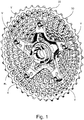
- a cassette 10 and a body 50 intended for a bicycle transmission (not shown as a whole), are shown.
- the body 50 is intended for mounting on a hub of a bicycle rear wheel (not shown) by means of a free-wheel mechanism RL, per se known, only some recesses of which formed in the body 50 are visible in fig. 1 .
- the cassette 10 is shown mounted on the body 50, by means of screws V; clearly, in normal use the mounting of the cassette 10 on the body 50 takes place only after the latter has been mounted on the hub.
- the cassette 10 comprises a plurality of sprockets 11, fixedly connected to one another and adjacent along an axis; the axis of the cassette 10 coincides with an axis of the body 50, when they are mounted together; furthermore, the axis of the body 50 coincides with an axis of the hub, when the body 50 is mounted on the hub. Given the coinciding of these axes when the cassette 10, the body 50 and the hub are mounted together, hereinafter and in the figures they will all be indicated with reference symbol X.
- the cassette 10 illustrated in figs. 1 and 2 as well as in the other figures comprises twelve sprockets 11, each provided with teeth 12 separated by recesses 13; clearly, however, the number of sprockets 11 can be different according to requirements, as well as the number of teeth 12 (and of recesses 13) of each sprocket 11 is selected according to the requirements.
- the cassette 10 is made monolithic, from a single piece of material (preferably steel of the suitable type) suitably machined; preferably, this machining is carried out by means of a numerically-controlled machine tool, from a forged semi-machined product.
- the sprockets 11 are equally spaced apart in the direction of the axis X, by means of joining portions or connections 14, which are formed between pairs of adjacent sprockets 11 so as to be at the recesses 13 of the smallest sprocket 11 of the pair.
- the cassette 10 comprises an axial centering opening 15 (visible in fig. 2 or rather in figs. 8 and 9 ), intended for mounting centered on the body 50, without possibility of transmission of torque between cassette 10 and body 50.
- the centering opening 15 does not comprise any inner grooved profile or other elements suitable for a shape coupling with the body 20.
- the cassette 10 also comprises a plurality of attachment areas 20, intended to allow the attachment of the cassette to the body 50.
- the attachment areas 20 are arranged in the cassette 10 at a distance in the radial direction from the axis X greater, and indeed much greater, than the radius of the centering opening 15; preferably, the distance in the radial direction of the attachment areas 20 from the axis X is equal to at least three times, even more preferably from three to six times, the radius of the centering opening 15.
- Each of the attachment areas 20 comprises a support surface 21 and a threaded hole 22, formed in the material of the cassette 10 at the support surface 21, so as to be surrounded by it.
- the holes 22 can be through holes or blind holes, provided that they are of sufficient depth to receive the screws V in mounting on the body 50, as will be illustrated hereinafter.
- the centering opening 15 of the cassette 10 must allow the correct and precise positioning of the cassette 10 on the body 50.
- the centering opening 15 comprises an axial support area 31 and a radial support area 32: the first is formed from a conical surface, coaxial to the axis X, whereas the second is formed from a cylindrical surface, facing radially towards the axis X.
- the cassette 10, as stated, is intended to be mounted on the hub of a bicycle transmission by means of the body 50.
- the body 50 comprises two portions, a radially inner first portion 52 and a radially outer second portion 62; the two portions are fixedly connected to one another and are preferably obtained from a single piece, suitably shaped.
- the first portion 52 is intended to be mounted on the hub, whereas the second portion 62 is intended to receive the cassette 10.
- the first portion 52 has a tubular shape and extends axially from a first face 55 to a second face 56 of the body 50; it thus has axial extension equal to that of the body 50 itself.
- the second portion 62 has shorter axial extension than that of the first portion 52, preferably less than 1/4 of it.
- the first portion 52 comprises an axial cavity 57, extending along the axis X and intended for coupling with the hub, through the free-wheel mechanism RL.
- the first portion 52 also comprises a radially outer surface 58, substantially cylindrical, extending in the axial direction between the second portion 62 of the body 50 and the first face 55, intended for coupling with the cassette 10.
- the second portion 62 extends radially outwards from the first portion 52 and comprises spider legs 63 (for example five spider legs 63, as shown in figures) that give the second portion 62 a star shape.
- the second portion 62 comprises a plurality of attachment areas 70 for the cassette 10, which are thus in radially outer position with respect to the first portion 52 of the body 50.
- attachment areas 70 of the illustrated body 50 are equally spaced in the circumferential direction around the axis X, i.e. angularly spaced apart by 72°.
- Each of the attachment areas 70 comprises a support surface 71 and at least one first hole 72, formed passing through the thickness of the second portion 62 of the body 50 at the support surface 71, so as to be surrounded by it.
- the support surfaces 71 are all coplanar to one another and perpendicular to the axis X.
- a second hole 73 is also provided, also passing through the thickness of the second portion 62 of the body 50 and at the same support surface 71.
- Two series of through holes are thus formed, a first series of first holes 72 and a second series of second holes 73; the holes of each series are arranged the same radial distance from the axis X, with the first holes 72 arranged a shorter distance from the axis X than the second holes 73.
- the attachment areas 70 are provided at each spider leg 63, in particular at the end 64 of every spider leg 63.
- the support surfaces 71 thus extend radially outwards, up to the ends 64, i.e. the outward radial extension of the support surfaces 71 corresponds to the outward radial extension of the second portion 62 of the body 50 and thus to the outward axial extension of the body 50 itself.
- the spider legs 63 of the body 50 are configured so that the mechanical stresses, determined by the drive torque transmitted from the cassette 10 to the hub through the body 50, are distributed as evenly as possible. Therefore, the profile of the spider legs 63 is broadly rounded, both close to the ends 64 and to the base, towards the first portion 52 of the body 50. Furthermore, the areas of the spider legs 63 not engaged by significant stresses are removed to lighten the body 50, with formation of an opening 65 at the base of every spider leg 63.
- Figs. 10 to 12 and figs. 13 to 15 illustrate a cassette 110, 210 and a body 150, 250 according to a second and a third embodiment of the invention, which differ from what has been described up to here and shown in figs. 1-9 only for the slightly different way of centering the cassette 110, 210 on the body 150, 250. Therefore, all details of the cassette 110, 210 and of the body 150, 250 that are identical to the corresponding details of the cassette 10 and of the body 50 are not described here; in figures 10-12 and 13-15 as well as in the following description, these details are indicated by the same reference numerals as the corresponding details of the cassette 10 and of the body 50; only the analogous but different details are indicated by reference numerals increased by 100 and by 200, respectively.
- the centering opening 115 of the cassette 110 comprises an axial support area 131 and a radial support area 132: the first is formed from an annular flat surface, perpendicular to the axis X, whereas the second is formed from a cylindrical surface, facing radially towards the axis X.
- the body 150 has a greater extension in the axial direction.
- the centering opening 215 of the cassette 210 comprises an axial support area 231 and a radial support area 232: the first is formed from an annular flat surface, perpendicular to the axis X, whereas the second is formed from a cylindrical surface, facing radially outwards.
- the body 250 has an extension in the axial direction analogous to the body 150.
- the cassette 10, 110, 210 and the body 50,150,250 are used together, to transmit the drive torque to the hub, just as the cassettes and the bodies of the prior art are used together for the same purpose.
- the torque is transmitted not by a shape coupling close to the axis X, but rather by the friction between the support surfaces 21 and the support surfaces 71, pressed against one another by the screws V, inserted in the through holes 72 or 73 and clamped in the threaded holes 22.
- the presence of the two series of through holes 72 and 73 makes it possible to mount equal cassettes 10, 110, 210 of two different sizes on bodies 50, 150, 250: small-sized cassettes, for which the first series of holes 72 is used, closer to the axis X, and larger-sized cassettes, for which the second series of holes 73 is used. This possibility increases the versatility of transmission.
- the torque is thus transmitted through areas relatively far from the axis X, with a double advantage.
- the minimum dimension constraint for the smallest sprocket of the cassette which does not need to be engaged with any shape coupling and can thus be as small as required by the transmission requirements is eliminated.
- the stress exchanged between the cassette and the body, for the same torque transmitted becomes lower thanks to the greater application arm with respect to the axis X.
- the coupling between the cassette and the body is carried out in a very simple manner through the screws V, without therefore the need for tools or special equipment: a normal tool is sufficient to actuate the screws V, i.e. - depending on the shape of the head of the screws V- a screwdriver, a hexagonal key, a Torx key or other suitable key.
- a normal tool is sufficient to actuate the screws V, i.e. - depending on the shape of the head of the screws V- a screwdriver, a hexagonal key, a Torx key or other suitable key.
- the mounting and dismounting operations take little time, thus allowing quick replacements, for example during races.
- an assembly of cassette and body according to the invention is lighter than an analogous assembly of the prior art, due particularly to the smaller number of pieces and the more effective transmission of stresses due to the torque transmitted.
Landscapes
- Engineering & Computer Science (AREA)
- Mechanical Engineering (AREA)
- Chemical & Material Sciences (AREA)
- Combustion & Propulsion (AREA)
- Transportation (AREA)
- General Engineering & Computer Science (AREA)
- Gears, Cams (AREA)
- Axle Suspensions And Sidecars For Cycles (AREA)
Claims (6)
- Körper zum Einbau einer Kassette (10; 110; 210) auf einer Hinterradnabe eines Fahrrads, umfassend:- einen ersten, rohrförmigen radialen Innenabschnitt (52) mit einem axialen Hohlraum (57), der auf einer Achse (X) des Körpers angeordnet und durch ein Freilaufsystem (RL) zum Ankoppeln an die Nabe bestimmt ist, und eine radialen Außenfläche (58), die zum Einbau der Kassette (10; 110; 210) bestimmt ist, wobei der erste Abschnitt (52) eine axiale Erstreckung zwischen einer ersten Seite (55) und einer zweiten Seite (56) des Körpers aufweist, und- einen zweiten radialen Außenabschnitt (62), der zum Ankoppeln an die Kassette (10; 110; 210) bestimmt ist, wobei der zweite Abschnitt (62):- eine kürzere axiale Erstreckung als die axiale Erstreckung des ersten Abschnitts (52) aufweist;- sich radial auswärts von dem ersten Abschnitt (52) erstreckt; und- eine Mehrzahl von Anbauräumen (70) für die Kassette (10; 110; 210) umfasst;wobei die Anbauräume (70) jeweils eine Auflagefläche (71) für die Kassette (10; 110; 210) und mindestens eine Bohrung (72; 73) in der Auflagefläche (71) umfassen, wobei die Bohrung (72, 73) direkt durch die axiale Dicke des zweiten Abschnitts (62) des Körpers hindurchgeht;
wobei die Bohrungen (72, 73) eines jeden Anbauraumes (70) in zwei Reihen unterteilt sind, eine erste Reihe von Bohrungen (72) in einem ersten radialen Abstand von der Achse (X) des Körpers und eine zweite Reihe von Bohrungen (73) in einem zweiten radialen Abstand von der Achse (X) des Körpers, der größer als der erste radiale Abstand ist;
dadurch gekennzeichnet, dass jeder Anbauraum (70) eine Bohrung (72) der ersten Reihen und eine Bohrung (73) der zweiten Reihen in derselben Auflagefläche (71) umfasst. - Körper nach Anspruch 1, wobei die Auflageflächen (71) des Anbauraumes (70) zueinander koplanar und senkrecht zur Achse (X) des Körpers sind.
- Körper nach Anspruch 1, wobei die Auflageflächen (71) des Anbauraumes (70) sich so weit radial auswärts erstrecken wie der zweite Abschnitt (62).
- Körper nach Anspruch 1, wobei der zweite Abschnitt (62) des Körpers sternförmig ist, umfassend eine Mehrzahl von Dornhalterstegen (63), wobei jeder Dornhaltersteg (63) einen der Anbauräume (70) an seinem äußeren radialen Ende (64) umfasst.
- Körper nach Anspruch 1, wobei die Anbauräume (70) in umfangseitiger Richtung rund um die Achse (X) des Körpers gleichmäßig voneinander beabstandet sind.
- Kit-of-parts, umfassend eine
Kassette, die zum Einbau in die Hinterradnabe eines Fahrrads mittels eines Körpers (50; 150; 250) nach Anspruch 1 geeignet ist,
und
umfassend einen Körper (50; 150; 250) nach einem der Ansprüche 1-5 und eine Kassette (10; 110; 210).
Applications Claiming Priority (1)
| Application Number | Priority Date | Filing Date | Title |
|---|---|---|---|
| IT102017000115411A IT201700115411A1 (it) | 2017-10-13 | 2017-10-13 | Corpetto per mozzo di ruota posteriore di bicicletta e pacco pignoni atto ad essere montato sul mozzo mediante tale corpetto |
Publications (2)
| Publication Number | Publication Date |
|---|---|
| EP3470321A1 EP3470321A1 (de) | 2019-04-17 |
| EP3470321B1 true EP3470321B1 (de) | 2020-12-02 |
Family
ID=61025006
Family Applications (1)
| Application Number | Title | Priority Date | Filing Date |
|---|---|---|---|
| EP18199101.9A Active EP3470321B1 (de) | 2017-10-13 | 2018-10-08 | Körper für eine fahrradhinterradnabe und mit solch einem körper an der nabe montierbare kassette |
Country Status (5)
| Country | Link |
|---|---|
| US (1) | US11199252B2 (de) |
| EP (1) | EP3470321B1 (de) |
| CN (1) | CN109665057A (de) |
| IT (1) | IT201700115411A1 (de) |
| TW (1) | TWI788431B (de) |
Cited By (1)
| Publication number | Priority date | Publication date | Assignee | Title |
|---|---|---|---|---|
| US12503197B2 (en) | 2020-09-01 | 2025-12-23 | Sram Deutschland Gmbh | Multi-sprocket arrangement for a rear wheel assembly for a bicycle, and rear wheel assembly |
Families Citing this family (8)
| Publication number | Priority date | Publication date | Assignee | Title |
|---|---|---|---|---|
| DE102017000855A1 (de) * | 2017-01-31 | 2018-08-02 | Sram Deutschland Gmbh | Mehrfach-Ritzelanordnung mit Schweißverbindung |
| IT201700115407A1 (it) * | 2017-10-13 | 2019-04-13 | Campagnolo Srl | Pacco pignoni e corpetto per il suo montaggio su un mozzo di ruota posteriore di bicicletta |
| IT201700115411A1 (it) | 2017-10-13 | 2019-04-13 | Campagnolo Srl | Corpetto per mozzo di ruota posteriore di bicicletta e pacco pignoni atto ad essere montato sul mozzo mediante tale corpetto |
| TWI821507B (zh) | 2019-01-29 | 2023-11-11 | 義大利商坎帕克諾羅公司 | 具有增大躍變的後變速盤 |
| IT201900013287A1 (it) | 2019-07-30 | 2021-01-30 | Campagnolo Srl | Adattatore per un corpo porta-pignoni per una ruota posteriore di bicicletta |
| TWI839545B (zh) * | 2019-07-30 | 2024-04-21 | 義大利商坎帕克諾羅公司 | 用於自行車後輪的變速盤和子組件 |
| USD1040033S1 (en) * | 2022-11-16 | 2024-08-27 | Sram Deutschland Gmbh | Bicycle sprocket assembly |
| US12420889B1 (en) * | 2024-03-22 | 2025-09-23 | Sram, Llc | Sprocket assembly |
Family Cites Families (62)
| Publication number | Priority date | Publication date | Assignee | Title |
|---|---|---|---|---|
| US4380445A (en) | 1974-08-16 | 1983-04-19 | Shimano Industrial Company Limited | Transmission for a bicycle |
| JPS61115790U (de) | 1984-12-29 | 1986-07-22 | ||
| FR2586601A1 (fr) | 1985-08-30 | 1987-03-06 | Maillard Maurice Ets | Procede pour la fabrication d'un corps de roue libre a trois pignons, ainsi que les roues libres obtenues |
| US4741724A (en) | 1986-12-15 | 1988-05-03 | Wang Chen Tsan | Chain wheel |
| JPH04297390A (ja) * | 1991-03-27 | 1992-10-21 | Shimano Inc | 自転車後輪用多段ホイール |
| JP3578541B2 (ja) * | 1996-02-20 | 2004-10-20 | 株式会社エクセディ | 粘性ダンパー機構 |
| EP1407962A1 (de) * | 2002-10-11 | 2004-04-14 | Campagnolo Srl | Tragstruktur für Fahrradzahnkränze |
| DE10260565B4 (de) * | 2002-12-21 | 2016-09-15 | Sram Deutschland Gmbh | Zahnkranzpaket |
| DE10342638B4 (de) * | 2003-09-16 | 2017-02-23 | Sram Deutschland Gmbh | Ritzeleinheit für eine Kettenschaltung eines Fahrrades |
| DE102004027963B4 (de) * | 2004-06-08 | 2015-12-24 | Sram Deutschland Gmbh | Vernietetes Zahnkranzpaket |
| US8057338B2 (en) * | 2005-08-30 | 2011-11-15 | Shimano, Inc. | Bicycle sprocket apparatus with reinforcement between sprockets |
| US20080004143A1 (en) * | 2006-06-16 | 2008-01-03 | Shimano Inc. | Bicycle sprocket assembly |
| JP2008189254A (ja) | 2007-02-07 | 2008-08-21 | Shimano Inc | 自転車用リアスプロケット組立体及びスプロケット |
| US9150280B2 (en) * | 2007-03-21 | 2015-10-06 | Sram, Llc | Bicycle multi-gear cassette |
| ITMI20071658A1 (it) * | 2007-08-09 | 2009-02-10 | Campagnolo Srl | Modulo di pignoni per una bicicletta e pacco pignoni comprendente tale modulo |
| ITMI20071661A1 (it) * | 2007-08-09 | 2009-02-10 | Campagnolo Srl | Assieme di ruote dentate per una bicicletta |
| ITMI20071659A1 (it) * | 2007-08-09 | 2009-02-10 | Campagnolo Srl | Assieme di pignoni per una ruota posteriore di bicicletta e pacco pignoni comprendente tale assieme |
| US7871347B2 (en) * | 2007-10-11 | 2011-01-18 | Shimano Inc. | Bicycle rear sprocket assembly |
| US8197371B2 (en) | 2008-01-24 | 2012-06-12 | Specialized Bicycle Components, Inc. | Cogset assembly for a bicycle |
| US20100099530A1 (en) * | 2008-03-28 | 2010-04-22 | Douglas Chiang | Bicycle Cogset |
| US20100009794A1 (en) * | 2008-07-10 | 2010-01-14 | Douglas Chiang | Sprocket assembly |
| US9193416B2 (en) * | 2009-11-30 | 2015-11-24 | Shimano Inc. | Bicycle sprocket support assembly |
| US8641151B2 (en) * | 2010-11-12 | 2014-02-04 | Shimano Inc. | Sprocket support structure |
| DE102010053597B4 (de) | 2010-12-07 | 2021-12-02 | Sram Deutschland Gmbh | Mehrfach-Kettenradanordnung für ein Fahrrad |
| US8905878B2 (en) * | 2011-01-28 | 2014-12-09 | Shimano (Singapore) Pte., Ltd. | Bicycle sprocket assembly |
| DE102011010855B4 (de) | 2011-02-10 | 2021-04-01 | Sram Deutschland Gmbh | Mehrfach-Ritzelanordnung mit einer Dämpfungseinrichtung |
| US8663044B2 (en) * | 2011-03-21 | 2014-03-04 | De-Hsin Lin | Sprocket assembly that is worked easily and quickly |
| US8968130B2 (en) * | 2011-03-23 | 2015-03-03 | Tien Hsin Industries Co., Ltd. | Bicycle cogset with support element |
| DE102011107162B4 (de) * | 2011-07-13 | 2024-02-22 | Sram Deutschland Gmbh | Mehrfach-Ritzelanordnung für eine Fahrradschaltung mit kleinen Ritzeln sowie Adapter hierfür |
| DE102012006771B4 (de) | 2012-04-03 | 2025-07-03 | Sram Deutschland Gmbh | Mehrfach-Ritzelanordnung für eine Fahrradschaltung mit kleinen Ritzeln sowie Adapter zur Anbringung der Mehrfach-Ritzelanordnung an einem Antreiber |
| TWI657965B (zh) | 2011-07-13 | 2019-05-01 | 矢倫德國股份有限公司 | 支載腳踏車變速器所用之備有小鏈輪的多鏈輪配置的傳動座體裝置 |
| US8956254B2 (en) * | 2011-08-04 | 2015-02-17 | Shimano Inc. | Bicycle sprocket assembly |
| TWM451318U (zh) * | 2012-07-25 | 2013-04-21 | Ad Ii Engineering Inc | 自行車鏈輪組 |
| CN202703831U (zh) * | 2012-07-26 | 2013-01-30 | 中山新宝精密科技有限公司 | 自行车后链轮组件 |
| TWM454980U (zh) * | 2012-10-23 | 2013-06-11 | de-xing Lin | 鏈輪結構 |
| US9533735B2 (en) | 2013-07-19 | 2017-01-03 | Sram Deutschland Gmbh | Multiple-sprocket arrangement for a bicycle gearing |
| TWM466030U (zh) * | 2013-07-19 | 2013-11-21 | Tokenproducts Inc | 棘輪座 |
| US9415835B2 (en) | 2014-01-24 | 2016-08-16 | Shimano Inc. | Rotatable annular bicycle component and bicycle rear sprocket |
| US9297450B2 (en) * | 2014-04-02 | 2016-03-29 | Shimano Inc. | Bicycle rear sprocket |
| US9604698B2 (en) * | 2014-10-22 | 2017-03-28 | Tien Hsin Industries Co., Ltd. | Bicycle cogset |
| US9604699B2 (en) | 2014-10-30 | 2017-03-28 | Tien Hsin Industries Co., Ltd. | Method for manufacturing bicycle cogset |
| DE102015203708A1 (de) * | 2015-03-02 | 2016-09-08 | Sram Deutschland Gmbh | Zahnrad für einen Fahrradantrieb |
| TWI554413B (zh) * | 2015-05-07 | 2016-10-21 | Chose Co Ltd | Combination of hub and flywheel |
| US9511819B1 (en) | 2015-05-25 | 2016-12-06 | Shimano Inc. | Bicycle rear sprocket assembly |
| DE202015005643U1 (de) | 2015-08-13 | 2015-09-25 | Sram Deutschland Gmbh | Mehrfach-Ritzelanordnung für Fahrräder |
| US10562588B2 (en) | 2015-09-01 | 2020-02-18 | The Hive Global, Inc | Bicycle cassette with locking connection |
| CN205769959U (zh) | 2016-05-17 | 2016-12-07 | 郑潇然 | 自行车用变速链轮 |
| US9868491B1 (en) | 2016-07-21 | 2018-01-16 | Shimano Inc. | Bicycle sprocket assembly |
| US10112681B2 (en) | 2016-07-21 | 2018-10-30 | Shimano Inc. | Bicycle sprocket supporting member and bicycle sprocket assembly |
| DE102016012229A1 (de) | 2016-10-13 | 2018-04-19 | Sram Deutschland Gmbh | Mehrfach-Ritzelanordnung und Fahrradantrieb mit einer solchen Mehrfach-Ritzelanordnung |
| DE102017000855A1 (de) | 2017-01-31 | 2018-08-02 | Sram Deutschland Gmbh | Mehrfach-Ritzelanordnung mit Schweißverbindung |
| US10315727B2 (en) | 2017-02-16 | 2019-06-11 | Shimano Inc. | Bicycle rear sprocket assembly |
| US10442496B2 (en) | 2017-03-29 | 2019-10-15 | Shimano Inc. | Bicycle sprocket assembly |
| EP3385153B1 (de) | 2017-04-07 | 2020-02-26 | ZUMA Innovation, S.L. | Kassette für ein fahrradgetriebesystem |
| US10773772B2 (en) | 2017-04-12 | 2020-09-15 | Shimano Inc. | Bicycle sprocket assembly |
| US10774915B2 (en) | 2017-05-30 | 2020-09-15 | Shimano Inc. | Bicycle sprocket assembly |
| WO2019040340A1 (en) | 2017-08-21 | 2019-02-28 | The Hive Global, Inc. | BICYCLE CASSETTE COMPRISING A CLAMP CONNECTION |
| JP2019064505A (ja) | 2017-10-03 | 2019-04-25 | 株式会社シマノ | 自転車用スプロケット |
| IT201700115407A1 (it) * | 2017-10-13 | 2019-04-13 | Campagnolo Srl | Pacco pignoni e corpetto per il suo montaggio su un mozzo di ruota posteriore di bicicletta |
| IT201700115411A1 (it) | 2017-10-13 | 2019-04-13 | Campagnolo Srl | Corpetto per mozzo di ruota posteriore di bicicletta e pacco pignoni atto ad essere montato sul mozzo mediante tale corpetto |
| CN107826207B (zh) | 2017-11-22 | 2019-05-07 | 湖南耐特材料科技有限公司 | 一种共用筒体的一体式飞轮及其制备方法 |
| US10864964B2 (en) | 2018-08-31 | 2020-12-15 | Shimano Inc. | Bicycle sprocket assembly |
-
2017
- 2017-10-13 IT IT102017000115411A patent/IT201700115411A1/it unknown
-
2018
- 2018-10-08 EP EP18199101.9A patent/EP3470321B1/de active Active
- 2018-10-11 TW TW107135742A patent/TWI788431B/zh active
- 2018-10-15 US US16/159,865 patent/US11199252B2/en active Active
- 2018-10-15 CN CN201811195161.5A patent/CN109665057A/zh active Pending
Non-Patent Citations (1)
| Title |
|---|
| None * |
Cited By (1)
| Publication number | Priority date | Publication date | Assignee | Title |
|---|---|---|---|---|
| US12503197B2 (en) | 2020-09-01 | 2025-12-23 | Sram Deutschland Gmbh | Multi-sprocket arrangement for a rear wheel assembly for a bicycle, and rear wheel assembly |
Also Published As
| Publication number | Publication date |
|---|---|
| CN109665057A (zh) | 2019-04-23 |
| US11199252B2 (en) | 2021-12-14 |
| EP3470321A1 (de) | 2019-04-17 |
| US20190113123A1 (en) | 2019-04-18 |
| TW201922557A (zh) | 2019-06-16 |
| TWI788431B (zh) | 2023-01-01 |
| IT201700115411A1 (it) | 2019-04-13 |
Similar Documents
| Publication | Publication Date | Title |
|---|---|---|
| EP3470321B1 (de) | Körper für eine fahrradhinterradnabe und mit solch einem körper an der nabe montierbare kassette | |
| US11052969B2 (en) | Cassette and body for mounting a cassette on a bicycle rear wheel hub | |
| EP3771630B1 (de) | Schaltkassette für ein fahrrad-hinterrad und zusammenbau eines ritzelträgerkörpers und einer solchen schaltkassette | |
| US9180929B2 (en) | Sprocket assembly | |
| US5882088A (en) | Bicycle hub | |
| US9580144B2 (en) | Sprocket assembly for a bicycle | |
| US8342994B2 (en) | Multiple sprocket assembly | |
| US20090215566A1 (en) | Multiple Sprocket Assembly | |
| EP1972539A2 (de) | Fahrrad-Mehrfachschaltungskassette | |
| EP3819201B1 (de) | Schaltkassetten-anordnung für ein fahrradhinterrad, ringmutter zur befestigung der anordnung und verfahren zur befestigung der schaltkassetten-anordnung | |
| EP3256759B1 (de) | Zahnradnabe mit elastischen zentrierelementen | |
| US9168976B1 (en) | Cassette and bicycle wheel assembly | |
| EP1972540A2 (de) | Fahrrad-Mehrfachschaltungskassette | |
| KR20110033131A (ko) | 체결 유닛을 포함하는 공구 | |
| US5332294A (en) | Bicycle hub freewheel assembly | |
| US8079288B2 (en) | Bicycle gear crank | |
| US5145471A (en) | Planet gear subunit of a planet gear unit | |
| US12454040B2 (en) | Bottom bracket tool | |
| EP4477521A1 (de) | Ringförmiger adapter, der eine antriebswelle mit einem kettenblatt verbindet | |
| CN219687549U (zh) | 一种自行车后轮驱动机构 | |
| US12187378B2 (en) | Pedal crank drive comprising a pedal crank and a chain ring, and production method | |
| CN210212655U (zh) | 一种自行车链轮中轴系统 | |
| US12441434B2 (en) | Multiple sprocket arrangement and modular sprocket arrangement system | |
| JP2025035887A (ja) | 人力駆動車用フリーホイール組立体 |
Legal Events
| Date | Code | Title | Description |
|---|---|---|---|
| PUAI | Public reference made under article 153(3) epc to a published international application that has entered the european phase |
Free format text: ORIGINAL CODE: 0009012 |
|
| STAA | Information on the status of an ep patent application or granted ep patent |
Free format text: STATUS: THE APPLICATION HAS BEEN PUBLISHED |
|
| AK | Designated contracting states |
Kind code of ref document: A1 Designated state(s): AL AT BE BG CH CY CZ DE DK EE ES FI FR GB GR HR HU IE IS IT LI LT LU LV MC MK MT NL NO PL PT RO RS SE SI SK SM TR |
|
| AX | Request for extension of the european patent |
Extension state: BA ME |
|
| STAA | Information on the status of an ep patent application or granted ep patent |
Free format text: STATUS: REQUEST FOR EXAMINATION WAS MADE |
|
| 17P | Request for examination filed |
Effective date: 20191016 |
|
| RBV | Designated contracting states (corrected) |
Designated state(s): AL AT BE BG CH CY CZ DE DK EE ES FI FR GB GR HR HU IE IS IT LI LT LU LV MC MK MT NL NO PL PT RO RS SE SI SK SM TR |
|
| GRAP | Despatch of communication of intention to grant a patent |
Free format text: ORIGINAL CODE: EPIDOSNIGR1 |
|
| STAA | Information on the status of an ep patent application or granted ep patent |
Free format text: STATUS: GRANT OF PATENT IS INTENDED |
|
| INTG | Intention to grant announced |
Effective date: 20200623 |
|
| GRAS | Grant fee paid |
Free format text: ORIGINAL CODE: EPIDOSNIGR3 |
|
| GRAA | (expected) grant |
Free format text: ORIGINAL CODE: 0009210 |
|
| STAA | Information on the status of an ep patent application or granted ep patent |
Free format text: STATUS: THE PATENT HAS BEEN GRANTED |
|
| AK | Designated contracting states |
Kind code of ref document: B1 Designated state(s): AL AT BE BG CH CY CZ DE DK EE ES FI FR GB GR HR HU IE IS IT LI LT LU LV MC MK MT NL NO PL PT RO RS SE SI SK SM TR |
|
| REG | Reference to a national code |
Ref country code: GB Ref legal event code: FG4D |
|
| REG | Reference to a national code |
Ref country code: AT Ref legal event code: REF Ref document number: 1340649 Country of ref document: AT Kind code of ref document: T Effective date: 20201215 Ref country code: CH Ref legal event code: EP |
|
| REG | Reference to a national code |
Ref country code: IE Ref legal event code: FG4D |
|
| REG | Reference to a national code |
Ref country code: DE Ref legal event code: R096 Ref document number: 602018010346 Country of ref document: DE |
|
| PG25 | Lapsed in a contracting state [announced via postgrant information from national office to epo] |
Ref country code: FI Free format text: LAPSE BECAUSE OF FAILURE TO SUBMIT A TRANSLATION OF THE DESCRIPTION OR TO PAY THE FEE WITHIN THE PRESCRIBED TIME-LIMIT Effective date: 20201202 Ref country code: RS Free format text: LAPSE BECAUSE OF FAILURE TO SUBMIT A TRANSLATION OF THE DESCRIPTION OR TO PAY THE FEE WITHIN THE PRESCRIBED TIME-LIMIT Effective date: 20201202 Ref country code: GR Free format text: LAPSE BECAUSE OF FAILURE TO SUBMIT A TRANSLATION OF THE DESCRIPTION OR TO PAY THE FEE WITHIN THE PRESCRIBED TIME-LIMIT Effective date: 20210303 Ref country code: NO Free format text: LAPSE BECAUSE OF FAILURE TO SUBMIT A TRANSLATION OF THE DESCRIPTION OR TO PAY THE FEE WITHIN THE PRESCRIBED TIME-LIMIT Effective date: 20210302 |
|
| REG | Reference to a national code |
Ref country code: NL Ref legal event code: MP Effective date: 20201202 |
|
| REG | Reference to a national code |
Ref country code: AT Ref legal event code: MK05 Ref document number: 1340649 Country of ref document: AT Kind code of ref document: T Effective date: 20201202 |
|
| PG25 | Lapsed in a contracting state [announced via postgrant information from national office to epo] |
Ref country code: BG Free format text: LAPSE BECAUSE OF FAILURE TO SUBMIT A TRANSLATION OF THE DESCRIPTION OR TO PAY THE FEE WITHIN THE PRESCRIBED TIME-LIMIT Effective date: 20210302 Ref country code: PL Free format text: LAPSE BECAUSE OF FAILURE TO SUBMIT A TRANSLATION OF THE DESCRIPTION OR TO PAY THE FEE WITHIN THE PRESCRIBED TIME-LIMIT Effective date: 20201202 Ref country code: LV Free format text: LAPSE BECAUSE OF FAILURE TO SUBMIT A TRANSLATION OF THE DESCRIPTION OR TO PAY THE FEE WITHIN THE PRESCRIBED TIME-LIMIT Effective date: 20201202 Ref country code: SE Free format text: LAPSE BECAUSE OF FAILURE TO SUBMIT A TRANSLATION OF THE DESCRIPTION OR TO PAY THE FEE WITHIN THE PRESCRIBED TIME-LIMIT Effective date: 20201202 |
|
| PG25 | Lapsed in a contracting state [announced via postgrant information from national office to epo] |
Ref country code: HR Free format text: LAPSE BECAUSE OF FAILURE TO SUBMIT A TRANSLATION OF THE DESCRIPTION OR TO PAY THE FEE WITHIN THE PRESCRIBED TIME-LIMIT Effective date: 20201202 Ref country code: NL Free format text: LAPSE BECAUSE OF FAILURE TO SUBMIT A TRANSLATION OF THE DESCRIPTION OR TO PAY THE FEE WITHIN THE PRESCRIBED TIME-LIMIT Effective date: 20201202 |
|
| REG | Reference to a national code |
Ref country code: LT Ref legal event code: MG9D |
|
| PG25 | Lapsed in a contracting state [announced via postgrant information from national office to epo] |
Ref country code: PT Free format text: LAPSE BECAUSE OF FAILURE TO SUBMIT A TRANSLATION OF THE DESCRIPTION OR TO PAY THE FEE WITHIN THE PRESCRIBED TIME-LIMIT Effective date: 20210405 Ref country code: RO Free format text: LAPSE BECAUSE OF FAILURE TO SUBMIT A TRANSLATION OF THE DESCRIPTION OR TO PAY THE FEE WITHIN THE PRESCRIBED TIME-LIMIT Effective date: 20201202 Ref country code: SK Free format text: LAPSE BECAUSE OF FAILURE TO SUBMIT A TRANSLATION OF THE DESCRIPTION OR TO PAY THE FEE WITHIN THE PRESCRIBED TIME-LIMIT Effective date: 20201202 Ref country code: LT Free format text: LAPSE BECAUSE OF FAILURE TO SUBMIT A TRANSLATION OF THE DESCRIPTION OR TO PAY THE FEE WITHIN THE PRESCRIBED TIME-LIMIT Effective date: 20201202 Ref country code: SM Free format text: LAPSE BECAUSE OF FAILURE TO SUBMIT A TRANSLATION OF THE DESCRIPTION OR TO PAY THE FEE WITHIN THE PRESCRIBED TIME-LIMIT Effective date: 20201202 Ref country code: CZ Free format text: LAPSE BECAUSE OF FAILURE TO SUBMIT A TRANSLATION OF THE DESCRIPTION OR TO PAY THE FEE WITHIN THE PRESCRIBED TIME-LIMIT Effective date: 20201202 Ref country code: EE Free format text: LAPSE BECAUSE OF FAILURE TO SUBMIT A TRANSLATION OF THE DESCRIPTION OR TO PAY THE FEE WITHIN THE PRESCRIBED TIME-LIMIT Effective date: 20201202 |
|
| PG25 | Lapsed in a contracting state [announced via postgrant information from national office to epo] |
Ref country code: AT Free format text: LAPSE BECAUSE OF FAILURE TO SUBMIT A TRANSLATION OF THE DESCRIPTION OR TO PAY THE FEE WITHIN THE PRESCRIBED TIME-LIMIT Effective date: 20201202 |
|
| REG | Reference to a national code |
Ref country code: DE Ref legal event code: R097 Ref document number: 602018010346 Country of ref document: DE |
|
| PG25 | Lapsed in a contracting state [announced via postgrant information from national office to epo] |
Ref country code: IS Free format text: LAPSE BECAUSE OF FAILURE TO SUBMIT A TRANSLATION OF THE DESCRIPTION OR TO PAY THE FEE WITHIN THE PRESCRIBED TIME-LIMIT Effective date: 20210402 |
|
| PLBE | No opposition filed within time limit |
Free format text: ORIGINAL CODE: 0009261 |
|
| STAA | Information on the status of an ep patent application or granted ep patent |
Free format text: STATUS: NO OPPOSITION FILED WITHIN TIME LIMIT |
|
| PG25 | Lapsed in a contracting state [announced via postgrant information from national office to epo] |
Ref country code: AL Free format text: LAPSE BECAUSE OF FAILURE TO SUBMIT A TRANSLATION OF THE DESCRIPTION OR TO PAY THE FEE WITHIN THE PRESCRIBED TIME-LIMIT Effective date: 20201202 |
|
| 26N | No opposition filed |
Effective date: 20210903 |
|
| PG25 | Lapsed in a contracting state [announced via postgrant information from national office to epo] |
Ref country code: DK Free format text: LAPSE BECAUSE OF FAILURE TO SUBMIT A TRANSLATION OF THE DESCRIPTION OR TO PAY THE FEE WITHIN THE PRESCRIBED TIME-LIMIT Effective date: 20201202 Ref country code: SI Free format text: LAPSE BECAUSE OF FAILURE TO SUBMIT A TRANSLATION OF THE DESCRIPTION OR TO PAY THE FEE WITHIN THE PRESCRIBED TIME-LIMIT Effective date: 20201202 |
|
| PG25 | Lapsed in a contracting state [announced via postgrant information from national office to epo] |
Ref country code: ES Free format text: LAPSE BECAUSE OF FAILURE TO SUBMIT A TRANSLATION OF THE DESCRIPTION OR TO PAY THE FEE WITHIN THE PRESCRIBED TIME-LIMIT Effective date: 20201202 |
|
| REG | Reference to a national code |
Ref country code: CH Ref legal event code: PL |
|
| PG25 | Lapsed in a contracting state [announced via postgrant information from national office to epo] |
Ref country code: IS Free format text: LAPSE BECAUSE OF FAILURE TO SUBMIT A TRANSLATION OF THE DESCRIPTION OR TO PAY THE FEE WITHIN THE PRESCRIBED TIME-LIMIT Effective date: 20210402 |
|
| REG | Reference to a national code |
Ref country code: BE Ref legal event code: MM Effective date: 20211031 |
|
| PG25 | Lapsed in a contracting state [announced via postgrant information from national office to epo] |
Ref country code: MC Free format text: LAPSE BECAUSE OF FAILURE TO SUBMIT A TRANSLATION OF THE DESCRIPTION OR TO PAY THE FEE WITHIN THE PRESCRIBED TIME-LIMIT Effective date: 20201202 |
|
| PG25 | Lapsed in a contracting state [announced via postgrant information from national office to epo] |
Ref country code: LU Free format text: LAPSE BECAUSE OF NON-PAYMENT OF DUE FEES Effective date: 20211008 Ref country code: BE Free format text: LAPSE BECAUSE OF NON-PAYMENT OF DUE FEES Effective date: 20211031 |
|
| PG25 | Lapsed in a contracting state [announced via postgrant information from national office to epo] |
Ref country code: LI Free format text: LAPSE BECAUSE OF NON-PAYMENT OF DUE FEES Effective date: 20211031 Ref country code: CH Free format text: LAPSE BECAUSE OF NON-PAYMENT OF DUE FEES Effective date: 20211031 |
|
| PG25 | Lapsed in a contracting state [announced via postgrant information from national office to epo] |
Ref country code: FR Free format text: LAPSE BECAUSE OF NON-PAYMENT OF DUE FEES Effective date: 20211031 |
|
| PG25 | Lapsed in a contracting state [announced via postgrant information from national office to epo] |
Ref country code: IE Free format text: LAPSE BECAUSE OF NON-PAYMENT OF DUE FEES Effective date: 20211008 |
|
| P01 | Opt-out of the competence of the unified patent court (upc) registered |
Effective date: 20230518 |
|
| GBPC | Gb: european patent ceased through non-payment of renewal fee |
Effective date: 20221008 |
|
| PG25 | Lapsed in a contracting state [announced via postgrant information from national office to epo] |
Ref country code: CY Free format text: LAPSE BECAUSE OF FAILURE TO SUBMIT A TRANSLATION OF THE DESCRIPTION OR TO PAY THE FEE WITHIN THE PRESCRIBED TIME-LIMIT Effective date: 20201202 |
|
| PG25 | Lapsed in a contracting state [announced via postgrant information from national office to epo] |
Ref country code: HU Free format text: LAPSE BECAUSE OF FAILURE TO SUBMIT A TRANSLATION OF THE DESCRIPTION OR TO PAY THE FEE WITHIN THE PRESCRIBED TIME-LIMIT; INVALID AB INITIO Effective date: 20181008 |
|
| PG25 | Lapsed in a contracting state [announced via postgrant information from national office to epo] |
Ref country code: GB Free format text: LAPSE BECAUSE OF NON-PAYMENT OF DUE FEES Effective date: 20221008 |
|
| PG25 | Lapsed in a contracting state [announced via postgrant information from national office to epo] |
Ref country code: MK Free format text: LAPSE BECAUSE OF FAILURE TO SUBMIT A TRANSLATION OF THE DESCRIPTION OR TO PAY THE FEE WITHIN THE PRESCRIBED TIME-LIMIT Effective date: 20201202 |
|
| PG25 | Lapsed in a contracting state [announced via postgrant information from national office to epo] |
Ref country code: MT Free format text: LAPSE BECAUSE OF FAILURE TO SUBMIT A TRANSLATION OF THE DESCRIPTION OR TO PAY THE FEE WITHIN THE PRESCRIBED TIME-LIMIT Effective date: 20201202 |
|
| PG25 | Lapsed in a contracting state [announced via postgrant information from national office to epo] |
Ref country code: TR Free format text: LAPSE BECAUSE OF FAILURE TO SUBMIT A TRANSLATION OF THE DESCRIPTION OR TO PAY THE FEE WITHIN THE PRESCRIBED TIME-LIMIT Effective date: 20201202 |
|
| PGFP | Annual fee paid to national office [announced via postgrant information from national office to epo] |
Ref country code: DE Payment date: 20251029 Year of fee payment: 8 |
|
| PGFP | Annual fee paid to national office [announced via postgrant information from national office to epo] |
Ref country code: IT Payment date: 20251021 Year of fee payment: 8 |