EP3470263A1 - Kippbrückenbordwand für ein kipperfahrzeug sowie ein damit ausgerüstetes kipperfahrzeug - Google Patents
Kippbrückenbordwand für ein kipperfahrzeug sowie ein damit ausgerüstetes kipperfahrzeug Download PDFInfo
- Publication number
- EP3470263A1 EP3470263A1 EP18199065.6A EP18199065A EP3470263A1 EP 3470263 A1 EP3470263 A1 EP 3470263A1 EP 18199065 A EP18199065 A EP 18199065A EP 3470263 A1 EP3470263 A1 EP 3470263A1
- Authority
- EP
- European Patent Office
- Prior art keywords
- sliding
- sliding door
- opening
- door
- guide
- Prior art date
- Legal status (The legal status is an assumption and is not a legal conclusion. Google has not performed a legal analysis and makes no representation as to the accuracy of the status listed.)
- Granted
Links
- 125000006850 spacer group Chemical group 0.000 claims description 4
- 238000009825 accumulation Methods 0.000 description 2
- 235000013339 cereals Nutrition 0.000 description 2
- 239000012530 fluid Substances 0.000 description 2
- 230000015572 biosynthetic process Effects 0.000 description 1
- 239000004464 cereal grain Substances 0.000 description 1
- 238000004140 cleaning Methods 0.000 description 1
- 238000010276 construction Methods 0.000 description 1
- 238000006073 displacement reaction Methods 0.000 description 1
- 230000000694 effects Effects 0.000 description 1
- 230000009969 flowable effect Effects 0.000 description 1
- 230000001404 mediated effect Effects 0.000 description 1
- 238000005070 sampling Methods 0.000 description 1
Images
Classifications
-
- B—PERFORMING OPERATIONS; TRANSPORTING
- B62—LAND VEHICLES FOR TRAVELLING OTHERWISE THAN ON RAILS
- B62D—MOTOR VEHICLES; TRAILERS
- B62D33/00—Superstructures for load-carrying vehicles
- B62D33/02—Platforms; Open load compartments
- B62D33/023—Sideboard or tailgate structures
- B62D33/027—Sideboard or tailgate structures movable
- B62D33/0276—Sideboard or tailgate structures movable by vertical translation
-
- B—PERFORMING OPERATIONS; TRANSPORTING
- B60—VEHICLES IN GENERAL
- B60P—VEHICLES ADAPTED FOR LOAD TRANSPORTATION OR TO TRANSPORT, TO CARRY, OR TO COMPRISE SPECIAL LOADS OR OBJECTS
- B60P1/00—Vehicles predominantly for transporting loads and modified to facilitate loading, consolidating the load, or unloading
- B60P1/04—Vehicles predominantly for transporting loads and modified to facilitate loading, consolidating the load, or unloading with a tipping movement of load-transporting element
- B60P1/26—Means for controlling movement of tailboards or sideboards
-
- B—PERFORMING OPERATIONS; TRANSPORTING
- B62—LAND VEHICLES FOR TRAVELLING OTHERWISE THAN ON RAILS
- B62D—MOTOR VEHICLES; TRAILERS
- B62D33/00—Superstructures for load-carrying vehicles
- B62D33/02—Platforms; Open load compartments
- B62D33/023—Sideboard or tailgate structures
- B62D33/027—Sideboard or tailgate structures movable
- B62D33/037—Latching means therefor
Definitions
- the invention relates to a Kipp stipulatenboard for a dump truck having an opening and a sliding door device with a sliding door for selectively closing and releasing the opening, wherein the sliding door between a closed position and an open position is displaced, so that the opening is blocked with located in the closure opening slide door - And is at least largely open when the sliding door is in the open position, wherein the sliding flap device comprises a sliding door during their movements between the closed position and the open position leading Schiebe entrysan eleven and an actuating mechanism for moving the sliding door, and wherein the sliding guide arrangement guideway elements for engaging the sliding door at two each other Having opposite, mutually parallel sliding door side edges, so that the guide track elements a Define the guide path parallel to the sliding door side edges for the movement of the sliding door.
- Kipp Portugalnboard of the aforementioned type can be found in particular as rear walls of dump trucks of dump trucks, in which the dumping is tilted about a rear-side tilting axis to slip free-flowing or fluid cargo from the dumping bridge.
- the respective Kipp Portugalnboard can be adjusted in total in a corresponding opening state, so that a maximum rear-side opening cross-section of the tipping bridge is released to deploy cargo.
- the opening provided therein and provided for their closure or release slide valve device normally serves to discharge flowable or fluid load in a well-controlled flow through the opening from the dumping bridge.
- the operator can use the actuating mechanism for moving the sliding door to adjust the free opening width of the opening respectively.
- Such dump trucks can be found for example in the field of agriculture for the transport of grain.
- the sliding door device with the slide door is also referred to as "grain shifter”. It is used to discharge the cereal grain dosed out of the tipping bridge, for example for sampling or for filling in containers, such as sacks.
- construction site vehicles such as Kiesransporter or Sandtransporter
- Kipp Germany construction site vehicles
- Kiesransporter or Sandtransporter can be equipped with such Kipp Portugaln, even with these vehicles, the sliding door device with the sliding door on the Kipp Portugalnbordwandö réelle serves to dump cargo, whether grainy or tough flowing, dosed well from the dumping bridge.
- the sliding guide arrangement is designed as a groove guide on both sliding side edges.
- guide track elements thus guide grooves are provided, in which the sliding door side edges are guided in their sliding movement.
- a disadvantage of these Kippmaschinen board walls that easily dirt, such as Ladegutreste, can accumulate in the guide, whereby the movement of the sliding door can be very stiff. A well-dosed controlling the sliding door movement can be made difficult or even impossible.
- the present invention has for its object to provide a Kipp stipulatenboard of the type mentioned, which is improved by simple means to the effect that the risk of dirt accumulation in the sliding guide is considerably reduced, so that caused by accumulation of dirt, unwanted binding of the sliding door effectively prevented can be.
- the sliding guide arrangement comprises a plurality of guideway members which are arranged at intervals from each other with the formation of free spaces between the guide along both sides of the opening in series.
- the guideway elements of the sliding guide arrangement of the tilting bridge side wall according to the invention are not continuous guide grooves but quasi-point guide elements.
- These guideway elements may be, for example, angled hook, so that they each have a protruding from the Kipp stipulatenbordwand spacers and a laterally projecting from the spacer, the slide door to the leadership outside overlapping overlapping section.
- they can also be designed mushroom-shaped, so that the mushroom-shaped section overlaps the sliding flap on the side edge of the sliding flap.
- Kipp Portugalnboard The particular advantage of Kipp Portugalnboard according to the invention is that dirt, which may initially be liable to the Schiebeklappenquestr Sn is stripped during the movement of the sliding door on the isolated track elements and thereby of the Sliding flap device may fall off.
- the spaces between the guideway elements can be selected so that no larger permanent collection points for dirt can form in the area of the guideway elements.
- the sliding flap device preferably has two carrier rails arranged laterally next to the opening, on which the guide rail elements are arranged.
- the guideway elements can therefore be preassembled on the carrier rails before the carrier rails are fastened laterally in their desired arrangement of the opening on the Kipp stipulatenbordwand. In this way, the assembly cost can be kept low.
- the actuating mechanism is formed according to a preferred embodiment of the invention as a manually operable lever mechanism having a manual operating lever, which is laterally foldable or extendable into an operating position, so that it is a sufficiently large lateral distance to the opening for a manual operating lever operated by the operator so that the operator does not critically come in contact with cargo flowing out of the port.
- the manual operating lever is in its operating position on the side edge of Kippmaschinenboard also laterally from. It is selectively pivotable up or down to move the slide door in the open position or in the closed position.
- the invention also provides a tipping bridge with a Kipp Griffinnboard to at least one of the preceding claims.
- the invention further relates to a dump truck with such a dumping bridge.
- the subject of the invention is also a slide-flap device set for a tilt-bridge onboard in which an opening is provided, the slide-flap device set being characterized by comprising a slide door and two support rails to be arranged along the side edges of the opening, each spaced a plurality of and in line with spacing between them lined up guideway elements for guiding the slide door on opposite sliding door side edges carries, so that the slide door is guided in the installed state on the Kipp stipulatenbordwand between a closed position and an open position, so that the opening is locked in befindlichem in the closed position sliding door - and befindmaschine in the open position Sliding door is at least substantially open, wherein the sliding door device set further comprises an actuating mechanism for displacing the sliding door.
- a tilting bridge wall prepared with a respective opening can be easily configured into a tilting bridge according to the invention according to at least one of claims 1 to 6.
- the tipping bridge 1 has two side walls 3, 4, a front wall 5 and a rear wall 7, which surround a loading area.
- the rear wall 7 is divided into two flap doors 9, 11 which are pivotable about normally vertical pivot axes 13, 15 from the closed position shown to an open position to adjust the rear side a maximum opening cross-section of the tipping bridge 1 for rapid or convenient unloading of cargo.
- Each of the two flap doors 9, 11 has a respective opening 16 with an associated sliding flap device 17.
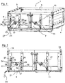
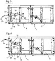
- FIG. 3 and FIG. 4 is the opening 16 in the left area of the flap door 9 in the partially open or fully open state recognizable.
- FIG. 1 the openings 16 of the rear wall 7 are closed by the sliding flap devices 17, 17, wherein the sliding flaps 21 are in their closed positions.
- FIG. 2 It can be seen that a manual operating lever 23 of a lever actuating mechanism 25 for moving the sliding door 21 from its secured position according to FIG. 1 out to a tilted in the example case pivot axis 27 is pivoted outwardly into an actuating position.
- An operator can thus operate with a mediated by the unfolded operating lever 23 safety distance to the opening 16, the lever actuating mechanism 25 to adjust the opening width of the opening 16.
- the sliding flap device 17 has a sliding door 21 in their movements between the closed position according to FIG. 1 and FIG. 2 and the maximum open position according to FIG. 4 leading sliding guide assembly 29, according to which are arranged close to both slide door side edges 31, 32 a plurality of mushroom-shaped or flachkopfnietförmige guideway elements 34 in a respective vertical row with distances from each other to form free spaces 36 therebetween, so that they with their widened head sections, the slide door 21 via the respective adjacent slide sliding side edges 31, 32 overlap by a few mm.
- the guide elements define in their series arrangement a linear guide path 39 parallel to the slide door side edges 31, 32.
- the thus designed slide guide assembly 29 provides reliable guidance of the slide door 21 in its movement between the closed position and the open position.
- the sliding flap device 17 acts quasi self-cleaning due to the thus designed sliding guide assembly 29, as any dirt on the slide door side edges 31, 32 is automatically stripped on the guide rail elements 34 during the movement of the sliding door 21 and therefore not in a Schiebeklappenbetruc Trentology Trent affecting manner in the sliding guide 29th can accumulate.
- the guideway elements 34 are provided preassembled on carrier rails 37, 38.
- the carrier rails 37, 38 are screwed to the rear wall 7.
- the lever actuating mechanism 25 is a translating lever mechanism which allows the slide door 21 to be moved between the closed position in accordance with a small amount of force and with a finely tuned displacement FIG. 1 and FIG. 2 and the maximum open position according to FIG. 4 to move.
Landscapes
- Engineering & Computer Science (AREA)
- Transportation (AREA)
- Mechanical Engineering (AREA)
- Chemical & Material Sciences (AREA)
- Combustion & Propulsion (AREA)
- Power-Operated Mechanisms For Wings (AREA)
- Support Devices For Sliding Doors (AREA)
- Wing Frames And Configurations (AREA)
Abstract
Description
- Die Erfindung betrifft eine Kippbrückenbordwand für ein Kipperfahrzeug, die eine Öffnung und eine Schiebeklappenvorrichtung mit eine Schiebeklappe zum wahlweisen Verschließen und Freigeben der Öffnung aufweist, wobei die Schiebeklappe zwischen einer Verschlussstellung und einer Öffnungsstellung geführt verschiebbar ist, so dass die Öffnung bei in Verschlussöffnung befindlicher Schiebeklappe versperrt - und bei in Öffnungsstellung befindlicher Schiebeklappe zumindest weitgehend offen ist, wobei die Schiebeklappenvorrichtung eine die Schiebeklappe bei deren Bewegungen zwischen der Verschlussstellung und der Öffnungsstellung führende Schiebeführungsanordnung und einen Betätigungsmechanismus zum Verschieben der Schiebeklappe umfasst, und wobei die Schiebeführungsanordnung Führungsbahnelemente zur Ineingriffnahme der Schiebeklappe an zwei einander entgegengesetzten, parallel zueinander verlaufenden Schiebeklappenseitenrändern aufweist, so dass die Führungsbahnelemente eine Führungsstrecke parallel zu den Schiebeklappenseitenrändern für die Bewegung der Schiebeklappe definieren.
- Kippbrückenbordwände der vorstehend genannten Art findet man insbesondere als Heckwände von Kippbrücken von Kipperfahrzeugen, bei denen die Kippbrücke um eine heckseitige Kippachse kippbar ist, um rieselfähiges oder fluides Ladegut von der Kippbrücke abrutschen zu lassen. Hierzu kann in den meisten Fällen die betreffende Kippbrückenbordwand insgesamt in einen entsprechenden Öffnungszustand eingestellt werden, so dass ein maximaler heckseitiger Öffnungsquerschnitt an der Kippbrücke freigegeben ist, um Ladegut auszubringen. Bei der hier betrachteten Kippbrückenbordwand dient die darin vorgesehene Öffnung und die zu deren Verschluss oder Freigabe vorgesehene Schiebeklappenvorrichtung normalerweise dazu, rieselfähiges oder fluides Ladegut in einem gut kontrollierten Mengenstrom durch die Öffnung hindurch aus der Kippbrücke auszulassen. Hierzu kann die Bedienungsperson den Betätigungsmechanismus zum Verschieben der Schiebeklappe benutzen, um die freie Öffnungsweite der Öffnung jeweils einzustellen.
- Derartige Kipperfahrzeuge kann man beispielsweise auch im Bereich der Landwirtschaft zum Transport von Getreidekorn finden. Dort wird die Schiebeklappenvorrichtung mit der Schiebeklappe auch als "Kornschieber" bezeichnet. Er wird dazu benutzt, das Getreidekorn dosiert aus der Kippbrücke auszulassen, etwa zur Probennahme oder zur Abfüllung in Behältnisse, etwa Säcke.
- Auch Baustellenfahrzeuge, wie etwa Kiestransporter oder Sandtransporter, können mit derartigen Kippbrücken ausgestattet sind, wobei auch bei diesen Fahrzeugen die Schiebeklappenvorrichtung mit der Schiebeklappe an der Kippbrückenbordwandöffnung dazu dient, Ladegut, sei es nun körnig oder zäh fließend, von der Kippbrücke gut dosiert abzulassen.
- Bei den bekannten Kippbrücken mit Kippbrückenbordwänden der hier betrachteten Art ist die Schiebeführungsanordnung als Nutführung an beiden Schiebeklappenseitenrändern ausgebildet. Als Führungsbahnelemente sind somit Führungsnuten vorgesehen, in denen die Schiebeklappenseitenränder bei ihrer Verschiebebewegung geführt sind. Nachteilig an diesen Kippbrückenbordwänden ist, dass sich in den Führungsnuten leicht Schmutz, wie etwa Ladegutreste, ansammeln kann, wodurch das Bewegen der Schiebeklappe sehr schwergängig werden kann. Ein gut dosiertes Steuern der Schiebeklappenbewegung kann dadurch erschwert oder gar unmöglich gemacht sein.
- Der vorliegenden Erfindung liegt die Aufgabe zugrunde, eine Kippbrückenbordwand der eingangs genannten Art bereitzustellen, welche mit einfachen Mitteln dahingehend verbessert ist, dass die Gefahr von Schmutzansammlungen im Bereich der Schiebeführungsanordnung erheblich reduziert ist, so dass eine durch Schmutzansammlungen verursachte, unerwünschte Schwergängigkeit der Schiebeklappe wirksam unterbunden werden kann.
- Zur Lösung dieser Aufgabe wird eine Kippbrückenbordwand der eingangs genannten Art vorgeschlagen, die dadurch gekennzeichnet ist, dass die Schiebeführungsanordnung mehrere Führungsbahnelemente aufweist, die mit Abständen voneinander unter Bildung von Freiräumen dazwischen längs der Führungsstrecke beidseitig der Öffnung in Reihe angeordnet sind.
- Im Unterschied zum Stand der Technik handelt es sich bei den Führungsbahnelementen der Schiebeführungsanordnung der erfindungsgemäßen Kippbrückenbordwand nicht um durchgehende Führungsnuten, sondern um quasi punktuelle Führungselemente.
- Diese Führungsbahnelemente können beispielsweise winkelhakenförmig sein, so dass sie jeweils einen von der Kippbrückenbordwand abstehenden Abstandshalter und einen von dem Abstandshalter seitlich abstehenden, die Schiebeklappe zu deren Führung außen überlappenden Überlappungsabschnitt aufweisen. Sie können andererseits auch pilzförmig ausgestaltet sein, so dass der pilzkopfförmige Abschnitt die Schiebeklappe am Schiebeklappenseitenrand überlappt.
- Der besondere Vorteil der Kippbrückenbordwand nach der Erfindung besteht darin, dass Schmutz, der ggf. zunächst an den Schiebeklappenseitenrändern haftet, bei der Bewegung der Schiebeklappe an den vereinzelten Führungsbahnelementen abgestreift wird und dabei von der Schiebeklappenvorrichtung abfallen kann. Die Zwischenräume zwischen den Führungsbahnelementen können so gewählt sein, dass sich im Bereich der Führungsbahnelemente keine größeren Dauersammelstellen für Schmutz bilden können.
- Vorzugsweise weist die Schiebeklappenvorrichtung zwei seitlich neben der Öffnung angeordnete Trägerschienen auf, an denen die Führungsbahnelemente angeordnet sind. Die Führungsbahnelemente können daher bereits an den Trägerschienen vormontiert werden, bevor die Trägerschienen in ihrer Soll-Anordnung seitlich der Öffnung an der Kippbrückenbordwand befestigt werden. Auf diese Weise kann der Montageaufwand gering gehalten werden.
- Der Betätigungsmechanismus ist gemäß einer bevorzugten Ausführungsform der Erfindung als ein von Hand betätigbarer Hebelmechanismus ausgebildet, der einen Handbetätigungshebel aufweist, welcher in eine Betätigungsstellung seitlich ausklappbar oder ausziehbar ist, so dass er für eine den Handbetätigungshebel bestimmungsgemäß betätigende Bedienungsperson einen hinreichend großen seitlichen Abstand zu der Öffnung bietet, so dass die Bedienungsperson nicht in kritischer Weise mit aus der Öffnung ausströmendem Ladegut in Berührung kommt. Vorzugsweise steht der Handbetätigungshebel in seiner Betätigungsstellung über den seitlichen Rand der Kippbrückenbordwand hinaus seitlich ab. Er ist dabei wahlweise nach oben oder nach unten schwenkbar, um die Schiebeklappe in die Öffnungsstellung bzw. in die Verschlussstellung zu bewegen.
- Gegenstand der Erfindung ist auch eine Kippbrücke mit einer Kippbrückenbordwand nach wenigstens einem der vorhergehenden Ansprüche.
- Gegenstand der Erfindung ist ferner ein Kipperfahrzeug mit einer solchen Kippbrücke.
- Gegenstand der Erfindung ist auch ein Schiebeklappenvorrichtungsset für eine Kippbrückenbordwand, in der eine Öffnung vorgesehen ist, wobei das Schiebeklappenvorrichtungsset dadurch gekennzeichnet ist, dass es eine Schiebeklappe und zwei längs der Seitenränder der Öffnung anzuordnende Trägerschienen umfasst, von denen jede mehrere voneinander beabstandete und auf einer Linie mit Abständen dazwischen aufgereihte Führungsbahnelemente zur Führung der Schiebeklappe an einander entgegengesetzten Schiebeklappenseitenrändern trägt, so dass die Schiebeklappe im Einbauzustand an der Kippbrückenbordwand zwischen einer Verschlussstellung und einer Öffnungsstellung geführt bewegbar ist, so dass die Öffnung bei in Verschlussstellung befindlicher Schiebeklappe versperrt - und bei in Öffnungsstellung befindlicher Schiebeklappe zumindest weitgehend offen ist, wobei das Schiebeklappenvorrichtungsset ferner einen Betätigungsmechanismus zum Verschieben der Verschiebeklappe umfasst.
- Mit dem Schiebeklappenvorrichtungsset lässt sich eine mit einer betreffenden Öffnung präparierte Kippbrückenbordwand auf einfache Weise zu einer erfindungsgemäßen Kippbrückenbordwand nach wenigstens einem der Ansprüche 1-6 ausgestalten.
- Ein Ausführungsbeispiel der Erfindung wird nachstehend unter Bezugnahme auf die Figuren näher erläutert.
- Figur 1
- zeigt in einer Perspektivdarstellung eine Kippbrücke mit einer Kippbrückenbordwand nach der Erfindung.
- Figur 2
- zeigt eine Draufsicht auf die Kippbrückenbordwand nach
Figur 1 mit einem in Betätigungsstellung ausgeklappten Handbetätigungshebel einer Schiebeklappenvorrichtung mit in Verschlussstellung befindlicher Schiebeklappe. - Figur 3
- zeigt eine Draufsicht auf die Kippbrückenbordwand, wobei die Schiebeklappe in einer die Bordwandöffnung teilweise freigebenden Zwischenstellung eingestellt ist.
- Figur 4
- zeigt eine Draufsicht auf die Bordwand, wobei die Schiebeklappe in ihrer maximalen Öffnungsstellung eingestellt ist.
- Die Kippbrücke 1 gemäß
Figur 1 weist zwei Seitenwände 3, 4, eine Frontwand 5 und eine Heckwand 7 auf, welche eine Ladefläche umgeben. - Im Beispielsfall ist die Heckwand 7 in zwei Klapptüren 9, 11 unterteilt, die um normalerweise vertikale Schwenkachsen 13, 15 aus der gezeigten Schließstellung in eine Öffnungsstellung schwenkbar sind, um heckseitig einen maximalen Öffnungsquerschnitt der Kippbrücke 1 für rasches bzw. bequemes Abladen von Ladegut einzustellen.
- Jede der beiden Klapptüren 9, 11 weist eine jeweilige Öffnung 16 mit einer zugehörigen Schiebeklappenvorrichtung 17 auf. In
Figur 3 und Figur 4 ist die Öffnung 16 im linken Bereich der Klapptür 9 im teilgeöffneten bzw. vollständig geöffneten Zustand erkennbar. - Da die Öffnungen 16 und Schiebeklappenvorrichtungen 17 beider Klapptüren 9, 11 im Wesentlichen gleichartig ausgestaltet sind, wird im Folgenden hauptsächlich auf die Öffnung 16 und Schiebeklappenvorrichtung 17 der in den Figuren linken Klapptür 9 Bezug genommen.
- In
Figur 1 sind die Öffnungen 16 der Heckwand 7 durch die Schiebeklappenvorrichtungen 17, 17 verschlossen, wobei die Schiebeklappen 21 in ihren Verschlussstellungen sind. - In
Figur 2 ist erkennbar, dass ein Handbetätigungshebel 23 eines Hebelbetätigungsmechanismus 25 zum Bewegen der Schiebeklappe 21 aus seiner gesicherten Stellung gemäßFigur 1 heraus um eine im Beispielsfall schräge Schwenkachse 27 nach außen in eine Betätigungsstellung verschwenkt ist. Eine Bedienungsperson kann somit mit einem durch den ausgeklappten Betätigungshebel 23 vermittelten Sicherheitsabstand zu der Öffnung 16 den Hebelbetätigungsmechanismus 25 bedienen, um die Öffnungsweite der Öffnung 16 einzustellen. - Die Schiebeklappenvorrichtung 17 weist eine die Schiebeklappe 21 bei deren Bewegungen zwischen der Verschlussstellung gemäß
Figur 1 und Figur 2 und der maximalen Öffnungsstellung gemäßFigur 4 führende Schiebeführungsanordnung 29 auf, gemäß welcher nahe an beiden Schiebeklappenseitenrändern 31, 32 mehrere pilzförmige oder flachkopfnietförmige Führungsbahnelemente 34 in einer jeweiligen vertikalen Reihe mit Abständen voneinander unter Bildung von Freiräumen 36 dazwischen angeordnet sind, so dass sie mit ihren erweiterten Kopfabschnitten die Schiebeklappe 21 über die jeweils benachbarten Schiebeklappenseitenränder 31, 32 hinweg um einige mm überlappen. Die Führungselemente definieren in ihrer Reihenanordnung eine lineare Führungsstrecke 39 parallel zu den Schiebeklappenseitenrändern 31, 32. Die so gestaltete Schiebeführungsanordnung 29 bietet eine zuverlässige Führung der Schiebeklappe 21 bei deren Bewegung zwischen der Verschlussstellung und der Öffnungsstellung. - Die Schiebeklappenvorrichtung 17 wirkt aufgrund der so gestalteten Schiebeführungsanordnung 29 quasi selbstreinigend, da etwaiger Schmutz an den Schiebeklappenseitenrändern 31, 32 bei der Bewegung der Schiebeklappe 21 automatisch an den Führungsbahnelementen 34 abgestreift wird und sich daher nicht in einer die Schiebeklappenbetätigung beeinträchtigenden Weise im Bereich die Schiebeführungsanordnung 29 ansammeln kann.
- Im gezeigten Beispielsfall sind die Führungsbahnelemente 34 an Trägerschienen 37, 38 vormontiert vorgesehen. Die Trägerschienen 37, 38 sind mit der Heckwand 7 verschraubt.
- Bei dem Hebelbetätigungsmechanismus 25 handelt es sich um einen übersetzenden Hebelmechanismus, welcher es erlaubt, die Schiebeklappe 21 mit geringem Kraftaufwand und bei fein abgestimmter Wegdosierung zwischen der Verschlussstellung gemäß
Figur 1 und Figur 2 und der maximalen Öffnungsstellung gemäßFigur 4 zu verschieben.
Claims (9)
- Kippbrückenbordwand (7) für ein Kipperfahrzeug, die eine Öffnung (16) und eine Schiebeklappenvorrichtung (17) mit einer Schiebeklappe (21) zum wahlweisen Verschließen und Freigeben der Öffnung (16) aufweist, wobei die Schiebeklappe (21) zwischen einer Verschlussstellung und einer Öffnungsstellung geführt verschiebbar ist, so dass die Öffnung (16) bei in Verschlussstellung befindlicher Schiebeklappe (21) versperrt- und bei in Öffnungsstellung befindlicher Schiebeklappe (21) zumindest weitgehend offen ist,
wobei die Schiebeklappenvorrichtung (17) eine die Schiebeklappe (21) bei deren Bewegungen zwischen der Verschlussstellung und der Öffnungsstellung führende Schiebeführungsanordnung (29) und einen Betätigungsmechanismus (25) zum Verschieben der Schiebeklappe (21) umfasst, und wobei die Schiebeführungsanordnung (29) Führungsbahnelemente (34) zur Ineingriffnahme der Schiebeklappe (21) an zwei einander entgegengesetzten, parallel zueinander verlaufenden Schiebeklappenseitenrändern (31, 32) aufweist, so dass die Führungsbahnelemente (34) eine Führungsstrecke (39) parallel zu den Schiebeklappenseitenrändern (31, 32) für die Bewegung der Schiebeklappe (21) definieren,
dadurch gekennzeichnet,
dass die Schiebeführungsanordnung (29) mehrere Führungsbahnelemente (34) aufweist, die mit Abständen voneinander unter Bildung von Freiräumen (36) dazwischen längs der Führungsstrecke (39) in Reihe angeordnet sind. - Kippbrückenbordwand nach Anspruch 1,
dadurch gekennzeichnet, dass die Führungsbahnelemente (34) jeweils einen von der Kippbrückenbordwand (7) abstehenden Abstandshalter und einen von dem Abstandshalter seitlich abstehenden, die Schiebeklappe (21) zu deren Führung überlappenden Überlappungsabschnitt aufweisen. - Kippbrückenbordwand nach Anspruch 1 oder 2, dadurch gekennzeichnet, dass die Führungsbahnelemente (34) winkelhakenförmig oder pilzförmig sind.
- Kippbrückenbordwand nach wenigstens einem der vorher gehenden Ansprüche, dadurch gekennzeichnet, dass die Schiebeklappenvorrichtung (17) zwei seitlich neben der Öffnung (16) angeordnete Trägerschienen (37, 38) aufweist, an denen die betreffenden Führungsbahnelemente (34) befestigt sind.
- Kippbrückenbordwand nach wenigstens einem der vorher gehenden Ansprüche, dadurch gekennzeichnet, dass der Betätigungsmechanismus (25) als ein von Hand betätigbarer Hebelmechanismus ausgebildet ist, der einen Handbetätigungshebel (23) aufweist, welcher in eine Betätigungsstellung seitlich ausklappbar oder ausziehbar ist, insbesondere so, dass er in seiner Betätigungsstellung über den Rand der Kippbrückenbordwand (7) hinaus seitlich absteht.
- Kippbrückenbordwand nach Anspruch 5, dadurch gekennzeichnet, dass der Betätigungshebel (23) in seiner Betätigungsstellung wahlweise nach oben oder nach unten schwenkbar ist, um die Schiebeklappe (21) in die Öffnungsstellung bzw. in die Verschlussstellung zu bewegen.
- Kippbrücke mit einer Kippbrückenbordwand (7) nach wenigstens einem der vorher gehenden Ansprüche.
- Kipperfahrzeug mit einer Kippbrücke nach Anspruch 7.
- Schiebeklappenvorrichtungsset für eine Kippbrückenbordwand, in der eine Öffnung vorgesehen ist, dadurch gekennzeichnet, dass es eine Schiebeklappe und zwei längs der Seitenränder der Öffnung anzuordnende Trägerschienen umfasst, von denen jede mehrere voneinander beabstandete und auf einer Linie aufgereihte Führungsbahnelemente zur Führung der Schiebeklappe an einander entgegen gesetzten Schiebeklappenseitenrändern trägt, so dass die Schiebeklappe im Einbauzustand an der Kippbrückenbordwand zwischen einer Verschlussstellung und einer Öffnungsstellung geführt bewegbar ist, so dass die Öffnung bei in Verschlussstellung befindlicher Schiebeklappe versperrt- und bei in Öffnungsstellung befindlicher Schiebeklappe zumindest weitgehend offen ist, wobei das Schiebeklappenvorrichtungsset ferner einen Betätigungsmechanismus zum Verschieben der Verschiebeklappe umfasst.
Priority Applications (1)
| Application Number | Priority Date | Filing Date | Title |
|---|---|---|---|
| PL18199065T PL3470263T3 (pl) | 2017-10-12 | 2018-10-08 | Burta zabudowy samowyładowczej dla pojazdu typu wywrotka, jak i wyposażony w nią pojazd typu wywrotka |
Applications Claiming Priority (1)
| Application Number | Priority Date | Filing Date | Title |
|---|---|---|---|
| DE102017218286.5A DE102017218286A1 (de) | 2017-10-12 | 2017-10-12 | Kippbrückenbordwand für ein Kipperfahrzeug sowie ein damit ausgerüstetes Kipperfahrzeug |
Publications (2)
| Publication Number | Publication Date |
|---|---|
| EP3470263A1 true EP3470263A1 (de) | 2019-04-17 |
| EP3470263B1 EP3470263B1 (de) | 2020-06-24 |
Family
ID=63798842
Family Applications (1)
| Application Number | Title | Priority Date | Filing Date |
|---|---|---|---|
| EP18199065.6A Active EP3470263B1 (de) | 2017-10-12 | 2018-10-08 | Kippbrückenbordwand für ein kipperfahrzeug sowie ein damit ausgerüstetes kipperfahrzeug |
Country Status (3)
| Country | Link |
|---|---|
| EP (1) | EP3470263B1 (de) |
| DE (1) | DE102017218286A1 (de) |
| PL (1) | PL3470263T3 (de) |
Citations (5)
| Publication number | Priority date | Publication date | Assignee | Title |
|---|---|---|---|---|
| US2174197A (en) * | 1938-11-18 | 1939-09-26 | Ryan Patrick | Endgate for vehicles |
| US2635688A (en) * | 1951-12-10 | 1953-04-21 | Ralph R Bruning | Endgate |
| US3482876A (en) * | 1967-12-21 | 1969-12-09 | Tajon Inc | Vehicle discharge apparatus |
| EP0113265A1 (de) * | 1982-12-03 | 1984-07-11 | Societe Nouvelle Des Ateliers De Venissieux | Vorrichtung zum Befestigen und Herunterschieben von Transportfahrzeugsseitenwänden |
| JPH0924760A (ja) * | 1995-07-14 | 1997-01-28 | Nippon Furuhaafu Kk | テールゲートリフタの摺動構造 |
Family Cites Families (5)
| Publication number | Priority date | Publication date | Assignee | Title |
|---|---|---|---|---|
| DE2532400C2 (de) * | 1975-07-19 | 1985-08-01 | Conrad Fahrzeugbau Ferdinand Conrad KG, 2804 Lilienthal | Bewegbare, mindestens zwei Wandabschnitte umfassende Begrenzungswand für die Ladefläche eines Fahrzeuges |
| US5890770A (en) * | 1997-11-26 | 1999-04-06 | Palmberg, Jr.; William C. | Dump vehicle with a positively controlled opening gate |
| US9211829B2 (en) * | 2013-06-11 | 2015-12-15 | Mac Trailer Manufacturing, Inc. | Locking door assembly for dump trailer and method of use |
| DE202013007557U1 (de) * | 2013-08-27 | 2013-10-17 | Huning Maschinenbau Gmbh | Fahrzeugaufbau für Nutzfahrzeuge |
| DE202016105059U1 (de) * | 2016-09-12 | 2017-04-25 | Stema Metalleichtbau Gmbh | Bordwandaufbau für die Ladefläche von Fahrzeugen, vorzugsweise von Anhängern als Dreiseitenkipper |
-
2017
- 2017-10-12 DE DE102017218286.5A patent/DE102017218286A1/de not_active Withdrawn
-
2018
- 2018-10-08 EP EP18199065.6A patent/EP3470263B1/de active Active
- 2018-10-08 PL PL18199065T patent/PL3470263T3/pl unknown
Patent Citations (5)
| Publication number | Priority date | Publication date | Assignee | Title |
|---|---|---|---|---|
| US2174197A (en) * | 1938-11-18 | 1939-09-26 | Ryan Patrick | Endgate for vehicles |
| US2635688A (en) * | 1951-12-10 | 1953-04-21 | Ralph R Bruning | Endgate |
| US3482876A (en) * | 1967-12-21 | 1969-12-09 | Tajon Inc | Vehicle discharge apparatus |
| EP0113265A1 (de) * | 1982-12-03 | 1984-07-11 | Societe Nouvelle Des Ateliers De Venissieux | Vorrichtung zum Befestigen und Herunterschieben von Transportfahrzeugsseitenwänden |
| JPH0924760A (ja) * | 1995-07-14 | 1997-01-28 | Nippon Furuhaafu Kk | テールゲートリフタの摺動構造 |
Also Published As
| Publication number | Publication date |
|---|---|
| PL3470263T3 (pl) | 2020-11-02 |
| EP3470263B1 (de) | 2020-06-24 |
| DE102017218286A1 (de) | 2019-04-18 |
Similar Documents
| Publication | Publication Date | Title |
|---|---|---|
| DE102017113053B4 (de) | Großladungsträger mit Schwenkklappe | |
| EP2871086B1 (de) | Fahrzeug mit Abdeckvorrichtung für den Ladeaufbau | |
| DE9412811U1 (de) | Sonnenschutzvorrichtung, insbesondere für lichtdurchlässige Sonnendächer | |
| DE2830192A1 (de) | Fahrzeugtuer, insbesondere fuer gewerbliche kraftfahrzeuge | |
| EP3470263B1 (de) | Kippbrückenbordwand für ein kipperfahrzeug sowie ein damit ausgerüstetes kipperfahrzeug | |
| EP1955932A2 (de) | Schließanordnung für einen Fahrzeugaufbau | |
| DE202014101421U1 (de) | Fahrzeug zum Transport von Flüssigkeiten und/oder Feststoffen | |
| DE10145000C1 (de) | Seitenwand für einen Lastwagen, Lastanhänger, Sattelauflieger od. dgl. | |
| EP1645462B1 (de) | Fahrzeug | |
| DE102010003932A1 (de) | Verdeckvorrichtung für einen Lastentransportbehälter | |
| DE3413506C1 (de) | Kastenaufbau,insbesondere fuer Lastfahrzeuge,mit einer aufklappbaren Seitenwand | |
| DE307313C (de) | ||
| DE507324C (de) | Selbstentladewagen | |
| DE10062156A1 (de) | Fahrzeugdach mit zwei hintereinander angeordneten, verschiebbaren Dachelementen | |
| DE3314941C1 (de) | Schwenkbare Spurlatte zur Freigabe von Anschlägen | |
| DE1964814B2 (de) | Schiebewand für Fahrzeuge, insbe sondere Eisenbahnguterwagen | |
| DE102008007639B4 (de) | Ladeaufbau für einen Lastkraftwagen | |
| EP0114265B1 (de) | Klapptritt für Schienenfahrzeuge | |
| DE20319167U1 (de) | Transportbehälteraufbau für ein Lastentransportfahrzeug | |
| DE9306550U1 (de) | Rolltor-Öffnungssystem | |
| DE2636704B2 (de) | Entladevorrichtung für seitlich entladende Transportwagen | |
| DE2137221B2 (de) | Entladevorrichtung für eine > Transportschute | |
| DE1274156B (de) | Gedeckter Eisenbahngueterwagen, dessen Seitenwaende aus je zwei in geschlossenem Zustand in einer Ebene liegenden Schiebewandteilen bestehen | |
| DE202008003336U1 (de) | Befestigungsvorrichtung an einer Ladefläche eines Fahrzeuges | |
| DE9203145U1 (de) | Verschlußvorrichtungen für Öffnungen von Fahrzeugaufbauten |
Legal Events
| Date | Code | Title | Description |
|---|---|---|---|
| PUAI | Public reference made under article 153(3) epc to a published international application that has entered the european phase |
Free format text: ORIGINAL CODE: 0009012 |
|
| STAA | Information on the status of an ep patent application or granted ep patent |
Free format text: STATUS: THE APPLICATION HAS BEEN PUBLISHED |
|
| AK | Designated contracting states |
Kind code of ref document: A1 Designated state(s): AL AT BE BG CH CY CZ DE DK EE ES FI FR GB GR HR HU IE IS IT LI LT LU LV MC MK MT NL NO PL PT RO RS SE SI SK SM TR |
|
| AX | Request for extension of the european patent |
Extension state: BA ME |
|
| STAA | Information on the status of an ep patent application or granted ep patent |
Free format text: STATUS: REQUEST FOR EXAMINATION WAS MADE |
|
| 17P | Request for examination filed |
Effective date: 20190916 |
|
| RBV | Designated contracting states (corrected) |
Designated state(s): AL AT BE BG CH CY CZ DE DK EE ES FI FR GB GR HR HU IE IS IT LI LT LU LV MC MK MT NL NO PL PT RO RS SE SI SK SM TR |
|
| GRAP | Despatch of communication of intention to grant a patent |
Free format text: ORIGINAL CODE: EPIDOSNIGR1 |
|
| STAA | Information on the status of an ep patent application or granted ep patent |
Free format text: STATUS: GRANT OF PATENT IS INTENDED |
|
| INTG | Intention to grant announced |
Effective date: 20200211 |
|
| GRAS | Grant fee paid |
Free format text: ORIGINAL CODE: EPIDOSNIGR3 |
|
| GRAA | (expected) grant |
Free format text: ORIGINAL CODE: 0009210 |
|
| STAA | Information on the status of an ep patent application or granted ep patent |
Free format text: STATUS: THE PATENT HAS BEEN GRANTED |
|
| AK | Designated contracting states |
Kind code of ref document: B1 Designated state(s): AL AT BE BG CH CY CZ DE DK EE ES FI FR GB GR HR HU IE IS IT LI LT LU LV MC MK MT NL NO PL PT RO RS SE SI SK SM TR |
|
| REG | Reference to a national code |
Ref country code: GB Ref legal event code: FG4D Free format text: NOT ENGLISH |
|
| REG | Reference to a national code |
Ref country code: CH Ref legal event code: EP |
|
| REG | Reference to a national code |
Ref country code: AT Ref legal event code: REF Ref document number: 1283562 Country of ref document: AT Kind code of ref document: T Effective date: 20200715 |
|
| REG | Reference to a national code |
Ref country code: DE Ref legal event code: R096 Ref document number: 502018001741 Country of ref document: DE |
|
| REG | Reference to a national code |
Ref country code: IE Ref legal event code: FG4D Free format text: LANGUAGE OF EP DOCUMENT: GERMAN |
|
| PG25 | Lapsed in a contracting state [announced via postgrant information from national office to epo] |
Ref country code: GR Free format text: LAPSE BECAUSE OF FAILURE TO SUBMIT A TRANSLATION OF THE DESCRIPTION OR TO PAY THE FEE WITHIN THE PRESCRIBED TIME-LIMIT Effective date: 20200925 Ref country code: NO Free format text: LAPSE BECAUSE OF FAILURE TO SUBMIT A TRANSLATION OF THE DESCRIPTION OR TO PAY THE FEE WITHIN THE PRESCRIBED TIME-LIMIT Effective date: 20200924 Ref country code: LT Free format text: LAPSE BECAUSE OF FAILURE TO SUBMIT A TRANSLATION OF THE DESCRIPTION OR TO PAY THE FEE WITHIN THE PRESCRIBED TIME-LIMIT Effective date: 20200624 Ref country code: FI Free format text: LAPSE BECAUSE OF FAILURE TO SUBMIT A TRANSLATION OF THE DESCRIPTION OR TO PAY THE FEE WITHIN THE PRESCRIBED TIME-LIMIT Effective date: 20200624 Ref country code: SE Free format text: LAPSE BECAUSE OF FAILURE TO SUBMIT A TRANSLATION OF THE DESCRIPTION OR TO PAY THE FEE WITHIN THE PRESCRIBED TIME-LIMIT Effective date: 20200624 |
|
| REG | Reference to a national code |
Ref country code: LT Ref legal event code: MG4D |
|
| PG25 | Lapsed in a contracting state [announced via postgrant information from national office to epo] |
Ref country code: BG Free format text: LAPSE BECAUSE OF FAILURE TO SUBMIT A TRANSLATION OF THE DESCRIPTION OR TO PAY THE FEE WITHIN THE PRESCRIBED TIME-LIMIT Effective date: 20200924 Ref country code: RS Free format text: LAPSE BECAUSE OF FAILURE TO SUBMIT A TRANSLATION OF THE DESCRIPTION OR TO PAY THE FEE WITHIN THE PRESCRIBED TIME-LIMIT Effective date: 20200624 Ref country code: LV Free format text: LAPSE BECAUSE OF FAILURE TO SUBMIT A TRANSLATION OF THE DESCRIPTION OR TO PAY THE FEE WITHIN THE PRESCRIBED TIME-LIMIT Effective date: 20200624 Ref country code: HR Free format text: LAPSE BECAUSE OF FAILURE TO SUBMIT A TRANSLATION OF THE DESCRIPTION OR TO PAY THE FEE WITHIN THE PRESCRIBED TIME-LIMIT Effective date: 20200624 |
|
| REG | Reference to a national code |
Ref country code: NL Ref legal event code: MP Effective date: 20200624 |
|
| PG25 | Lapsed in a contracting state [announced via postgrant information from national office to epo] |
Ref country code: AL Free format text: LAPSE BECAUSE OF FAILURE TO SUBMIT A TRANSLATION OF THE DESCRIPTION OR TO PAY THE FEE WITHIN THE PRESCRIBED TIME-LIMIT Effective date: 20200624 Ref country code: NL Free format text: LAPSE BECAUSE OF FAILURE TO SUBMIT A TRANSLATION OF THE DESCRIPTION OR TO PAY THE FEE WITHIN THE PRESCRIBED TIME-LIMIT Effective date: 20200624 |
|
| PG25 | Lapsed in a contracting state [announced via postgrant information from national office to epo] |
Ref country code: SM Free format text: LAPSE BECAUSE OF FAILURE TO SUBMIT A TRANSLATION OF THE DESCRIPTION OR TO PAY THE FEE WITHIN THE PRESCRIBED TIME-LIMIT Effective date: 20200624 Ref country code: RO Free format text: LAPSE BECAUSE OF FAILURE TO SUBMIT A TRANSLATION OF THE DESCRIPTION OR TO PAY THE FEE WITHIN THE PRESCRIBED TIME-LIMIT Effective date: 20200624 Ref country code: IT Free format text: LAPSE BECAUSE OF FAILURE TO SUBMIT A TRANSLATION OF THE DESCRIPTION OR TO PAY THE FEE WITHIN THE PRESCRIBED TIME-LIMIT Effective date: 20200624 Ref country code: EE Free format text: LAPSE BECAUSE OF FAILURE TO SUBMIT A TRANSLATION OF THE DESCRIPTION OR TO PAY THE FEE WITHIN THE PRESCRIBED TIME-LIMIT Effective date: 20200624 Ref country code: PT Free format text: LAPSE BECAUSE OF FAILURE TO SUBMIT A TRANSLATION OF THE DESCRIPTION OR TO PAY THE FEE WITHIN THE PRESCRIBED TIME-LIMIT Effective date: 20201026 Ref country code: ES Free format text: LAPSE BECAUSE OF FAILURE TO SUBMIT A TRANSLATION OF THE DESCRIPTION OR TO PAY THE FEE WITHIN THE PRESCRIBED TIME-LIMIT Effective date: 20200624 |
|
| PG25 | Lapsed in a contracting state [announced via postgrant information from national office to epo] |
Ref country code: SK Free format text: LAPSE BECAUSE OF FAILURE TO SUBMIT A TRANSLATION OF THE DESCRIPTION OR TO PAY THE FEE WITHIN THE PRESCRIBED TIME-LIMIT Effective date: 20200624 Ref country code: IS Free format text: LAPSE BECAUSE OF FAILURE TO SUBMIT A TRANSLATION OF THE DESCRIPTION OR TO PAY THE FEE WITHIN THE PRESCRIBED TIME-LIMIT Effective date: 20201024 |
|
| REG | Reference to a national code |
Ref country code: DE Ref legal event code: R097 Ref document number: 502018001741 Country of ref document: DE |
|
| PG25 | Lapsed in a contracting state [announced via postgrant information from national office to epo] |
Ref country code: DK Free format text: LAPSE BECAUSE OF FAILURE TO SUBMIT A TRANSLATION OF THE DESCRIPTION OR TO PAY THE FEE WITHIN THE PRESCRIBED TIME-LIMIT Effective date: 20200624 |
|
| PLBE | No opposition filed within time limit |
Free format text: ORIGINAL CODE: 0009261 |
|
| STAA | Information on the status of an ep patent application or granted ep patent |
Free format text: STATUS: NO OPPOSITION FILED WITHIN TIME LIMIT |
|
| 26N | No opposition filed |
Effective date: 20210325 |
|
| PG25 | Lapsed in a contracting state [announced via postgrant information from national office to epo] |
Ref country code: MC Free format text: LAPSE BECAUSE OF FAILURE TO SUBMIT A TRANSLATION OF THE DESCRIPTION OR TO PAY THE FEE WITHIN THE PRESCRIBED TIME-LIMIT Effective date: 20200624 Ref country code: LU Free format text: LAPSE BECAUSE OF NON-PAYMENT OF DUE FEES Effective date: 20201008 |
|
| REG | Reference to a national code |
Ref country code: BE Ref legal event code: MM Effective date: 20201031 |
|
| PG25 | Lapsed in a contracting state [announced via postgrant information from national office to epo] |
Ref country code: SI Free format text: LAPSE BECAUSE OF FAILURE TO SUBMIT A TRANSLATION OF THE DESCRIPTION OR TO PAY THE FEE WITHIN THE PRESCRIBED TIME-LIMIT Effective date: 20200624 Ref country code: BE Free format text: LAPSE BECAUSE OF NON-PAYMENT OF DUE FEES Effective date: 20201031 |
|
| PG25 | Lapsed in a contracting state [announced via postgrant information from national office to epo] |
Ref country code: IE Free format text: LAPSE BECAUSE OF NON-PAYMENT OF DUE FEES Effective date: 20201008 |
|
| REG | Reference to a national code |
Ref country code: CH Ref legal event code: PL |
|
| PG25 | Lapsed in a contracting state [announced via postgrant information from national office to epo] |
Ref country code: TR Free format text: LAPSE BECAUSE OF FAILURE TO SUBMIT A TRANSLATION OF THE DESCRIPTION OR TO PAY THE FEE WITHIN THE PRESCRIBED TIME-LIMIT Effective date: 20200624 Ref country code: MT Free format text: LAPSE BECAUSE OF FAILURE TO SUBMIT A TRANSLATION OF THE DESCRIPTION OR TO PAY THE FEE WITHIN THE PRESCRIBED TIME-LIMIT Effective date: 20200624 Ref country code: CY Free format text: LAPSE BECAUSE OF FAILURE TO SUBMIT A TRANSLATION OF THE DESCRIPTION OR TO PAY THE FEE WITHIN THE PRESCRIBED TIME-LIMIT Effective date: 20200624 |
|
| PG25 | Lapsed in a contracting state [announced via postgrant information from national office to epo] |
Ref country code: MK Free format text: LAPSE BECAUSE OF FAILURE TO SUBMIT A TRANSLATION OF THE DESCRIPTION OR TO PAY THE FEE WITHIN THE PRESCRIBED TIME-LIMIT Effective date: 20200624 |
|
| PG25 | Lapsed in a contracting state [announced via postgrant information from national office to epo] |
Ref country code: LI Free format text: LAPSE BECAUSE OF NON-PAYMENT OF DUE FEES Effective date: 20211031 Ref country code: CH Free format text: LAPSE BECAUSE OF NON-PAYMENT OF DUE FEES Effective date: 20211031 |
|
| GBPC | Gb: european patent ceased through non-payment of renewal fee |
Effective date: 20221008 |
|
| PG25 | Lapsed in a contracting state [announced via postgrant information from national office to epo] |
Ref country code: GB Free format text: LAPSE BECAUSE OF NON-PAYMENT OF DUE FEES Effective date: 20221008 |
|
| PGFP | Annual fee paid to national office [announced via postgrant information from national office to epo] |
Ref country code: FR Payment date: 20231026 Year of fee payment: 6 Ref country code: DE Payment date: 20230929 Year of fee payment: 6 Ref country code: CZ Payment date: 20231004 Year of fee payment: 6 Ref country code: AT Payment date: 20231020 Year of fee payment: 6 |
|
| PGFP | Annual fee paid to national office [announced via postgrant information from national office to epo] |
Ref country code: PL Payment date: 20231003 Year of fee payment: 6 |