EP3467325A1 - Scharnier und scharniervorrichtung eines mobilen endgeräts mit einem flexiblen bildschirm und mobiles endgerät mit einem flexiblen bildschirm - Google Patents
Scharnier und scharniervorrichtung eines mobilen endgeräts mit einem flexiblen bildschirm und mobiles endgerät mit einem flexiblen bildschirm Download PDFInfo
- Publication number
- EP3467325A1 EP3467325A1 EP17809555.0A EP17809555A EP3467325A1 EP 3467325 A1 EP3467325 A1 EP 3467325A1 EP 17809555 A EP17809555 A EP 17809555A EP 3467325 A1 EP3467325 A1 EP 3467325A1
- Authority
- EP
- European Patent Office
- Prior art keywords
- support body
- hinge
- flexible screen
- bracket
- mobile terminal
- Prior art date
- Legal status (The legal status is an assumption and is not a legal conclusion. Google has not performed a legal analysis and makes no representation as to the accuracy of the status listed.)
- Granted
Links
- 230000001360 synchronised effect Effects 0.000 claims abstract description 15
- 238000000034 method Methods 0.000 description 6
- 239000002184 metal Substances 0.000 description 3
- 239000000835 fiber Substances 0.000 description 2
- 238000003466 welding Methods 0.000 description 2
- 239000004677 Nylon Substances 0.000 description 1
- 101100012902 Saccharomyces cerevisiae (strain ATCC 204508 / S288c) FIG2 gene Proteins 0.000 description 1
- 229910000831 Steel Inorganic materials 0.000 description 1
- 238000004026 adhesive bonding Methods 0.000 description 1
- 239000004760 aramid Substances 0.000 description 1
- 229920003235 aromatic polyamide Polymers 0.000 description 1
- 238000005452 bending Methods 0.000 description 1
- 230000006835 compression Effects 0.000 description 1
- 238000007906 compression Methods 0.000 description 1
- 239000003292 glue Substances 0.000 description 1
- 238000012986 modification Methods 0.000 description 1
- 230000004048 modification Effects 0.000 description 1
- 229920001778 nylon Polymers 0.000 description 1
- 229920000728 polyester Polymers 0.000 description 1
- 229910001285 shape-memory alloy Inorganic materials 0.000 description 1
- 239000010959 steel Substances 0.000 description 1
- 239000002759 woven fabric Substances 0.000 description 1
Images


Classifications
-
- G—PHYSICS
- G06—COMPUTING; CALCULATING OR COUNTING
- G06F—ELECTRIC DIGITAL DATA PROCESSING
- G06F1/00—Details not covered by groups G06F3/00 - G06F13/00 and G06F21/00
- G06F1/16—Constructional details or arrangements
- G06F1/1613—Constructional details or arrangements for portable computers
- G06F1/1633—Constructional details or arrangements of portable computers not specific to the type of enclosures covered by groups G06F1/1615 - G06F1/1626
- G06F1/1637—Details related to the display arrangement, including those related to the mounting of the display in the housing
- G06F1/1652—Details related to the display arrangement, including those related to the mounting of the display in the housing the display being flexible, e.g. mimicking a sheet of paper, or rollable
-
- F—MECHANICAL ENGINEERING; LIGHTING; HEATING; WEAPONS; BLASTING
- F16—ENGINEERING ELEMENTS AND UNITS; GENERAL MEASURES FOR PRODUCING AND MAINTAINING EFFECTIVE FUNCTIONING OF MACHINES OR INSTALLATIONS; THERMAL INSULATION IN GENERAL
- F16C—SHAFTS; FLEXIBLE SHAFTS; ELEMENTS OR CRANKSHAFT MECHANISMS; ROTARY BODIES OTHER THAN GEARING ELEMENTS; BEARINGS
- F16C11/00—Pivots; Pivotal connections
- F16C11/04—Pivotal connections
- F16C11/12—Pivotal connections incorporating flexible connections, e.g. leaf springs
-
- G—PHYSICS
- G06—COMPUTING; CALCULATING OR COUNTING
- G06F—ELECTRIC DIGITAL DATA PROCESSING
- G06F1/00—Details not covered by groups G06F3/00 - G06F13/00 and G06F21/00
- G06F1/16—Constructional details or arrangements
- G06F1/1613—Constructional details or arrangements for portable computers
- G06F1/1633—Constructional details or arrangements of portable computers not specific to the type of enclosures covered by groups G06F1/1615 - G06F1/1626
- G06F1/1675—Miscellaneous details related to the relative movement between the different enclosures or enclosure parts
- G06F1/1681—Details related solely to hinges
-
- H—ELECTRICITY
- H04—ELECTRIC COMMUNICATION TECHNIQUE
- H04M—TELEPHONIC COMMUNICATION
- H04M1/00—Substation equipment, e.g. for use by subscribers
- H04M1/02—Constructional features of telephone sets
-
- H—ELECTRICITY
- H04—ELECTRIC COMMUNICATION TECHNIQUE
- H04M—TELEPHONIC COMMUNICATION
- H04M1/00—Substation equipment, e.g. for use by subscribers
- H04M1/02—Constructional features of telephone sets
- H04M1/0202—Portable telephone sets, e.g. cordless phones, mobile phones or bar type handsets
- H04M1/0206—Portable telephones comprising a plurality of mechanically joined movable body parts, e.g. hinged housings
- H04M1/0208—Portable telephones comprising a plurality of mechanically joined movable body parts, e.g. hinged housings characterized by the relative motions of the body parts
- H04M1/0214—Foldable telephones, i.e. with body parts pivoting to an open position around an axis parallel to the plane they define in closed position
- H04M1/0216—Foldable in one direction, i.e. using a one degree of freedom hinge
- H04M1/022—The hinge comprising two parallel pivoting axes
-
- H—ELECTRICITY
- H04—ELECTRIC COMMUNICATION TECHNIQUE
- H04M—TELEPHONIC COMMUNICATION
- H04M1/00—Substation equipment, e.g. for use by subscribers
- H04M1/02—Constructional features of telephone sets
- H04M1/0202—Portable telephone sets, e.g. cordless phones, mobile phones or bar type handsets
- H04M1/026—Details of the structure or mounting of specific components
- H04M1/0266—Details of the structure or mounting of specific components for a display module assembly
- H04M1/0268—Details of the structure or mounting of specific components for a display module assembly including a flexible display panel
Definitions
- the present invention relates to a mobile terminal and a hinge thereof.
- a flexible screen is an emerging screen.
- a mobile terminal with a flexible screen that is disposed outside the mobile terminal it is necessary to adapt to the change in length when the hinge is opened or closed.
- An object of the present invention is to provide a hinge of a mobile terminal with a flexible screen.
- the hinge can be applied in a mobile terminal with flexible screen, and the outer side of the hinge supports the flexible screen.
- the present invention adopts the following technical solutions:
- a hinge of a mobile terminal with a flexible screen, the outer side of which supports the flexible screen comprises a main support body provided with a rotating shaft of the hinge, a first bracket and a second bracket rotatably connected to a rotating shaft of the hinge, a first support body and a second support body respectively slidably connected to the first bracket and the second bracket, an auxiliary support body is separately provided between the first support body and the main support body and between the second support body and the main support body, and the auxiliary support body is correspondingly located at a bend portion of the hinge in a closed state;
- the hinge is further provided with a first guide structure rotating around the rotating shaft of the hinge together with the first bracket and a second guide structure rotating around the rotating shaft of the hinge together with the second bracket;
- the auxiliary support body between the first support body and the main support body is provided with a structure that is in guiding engagement with the first guide structure, and the auxiliary support body between the second support body and the main support body is provided with a structure that is in guiding engagement with the second guide structure;
- the auxiliary support body between the first support body and the main support body can rotate around the rotating shaft of the hinge together with the first bracket and self-rotate, the auxiliary support body between the second support body and the main support body can rotate around the rotating shaft of the hinge together with the second bracket and self-rotate, and the axis of the self-rotation is parallel to the rotating shaft of the hinge, and the center of self-rotation is located at or near the flexible screen support reference surface;
- the hinge is further provided with a synchronous control mechanism for synchronously rotating the first support body and the second support body with the rotating shaft of the hinge as an axis.
- the present invention further adopts the following technical solutions or combines these technical solutions.
- the hinge is further provided with a belt that is an elastic belt or a flexible belt or a belt that is tensioned by an elastic member or a flexible member; the belt passes through the auxiliary support body and the main support body from a path interesting the rotating shaft of the hinge, and smoothens the auxiliary support body during the rotation and under a stop state, to provide flat support for the flexible screen.
- a belt that is an elastic belt or a flexible belt or a belt that is tensioned by an elastic member or a flexible member
- a groove is disposed near the outer side of the auxiliary support body and the main support body, and the belt passes through the groove, and a plate is further connected to the notch.
- the first guide structure and the second guide structure are both guide grooves, and the auxiliary support body between the first support body and the main support body is provided with a guide pin that is engaged with the first guide structure, and the auxiliary support body between the second support body and the main support body is provided with a guide pin that is engaged with the first guide structure, such that when there are a plurality of auxiliary support bodies between the first support body and the main support body and between the second support body and the main support body, the plurality of auxiliary support bodies can rotate in sequence.
- the first guide structure is provided with a limiting structure for the structure that is in guiding engagement with the first guide structure, such that the relative position of the first guide structure and the structure that is in guiding engagement with the first guide structure is in a stable state when the hinge is in a closed state
- the second guide structure is provided with a limiting structure for the structure that is in guiding engagement with the second guide structure, such that the relative position of the second guide structure and the structure that is in guiding engagement with the second guide structure is in a stable state when the hinge is in a closed state.
- the synchronous control mechanism comprises a first swing arm and a second swing arm that are rotatably connected to the rotating shaft of the hinge, and the first swing arm and the second swing arm are respectively rotatably connected to one end of the first connecting rod and the second connecting rod, the rotation axes of the first connecting rod and second connecting rod are perpendicular to the rotating shaft of the hinge, and the other ends of the first connecting rod and the second connecting rod are respectively rotatably connected to the first support body and the second support body.
- the synchronous control mechanism is located inside of the flexible screen support reference surface and is not in the same plane as the flexible screen support reference surface.
- the rotating shafts of the hinge includes a first shaft and a second shaft in parallel, the first bracket is rotatably connected with the first shaft, the second bracket is rotatably connected with the second shaft, the first swing arm of the synchronous control mechanism is rotatably connected with the first shaft, and the second swing arm is rotatably connected with the second shaft.
- the hinge is further provided with a sheet that can be repeatedly bent; the sheet is located at the upper surface near the ends of the auxiliary support body and the main support body, and the two ends of the sheet are respectively connected to the first support body and the second support body.
- a first guide groove and a second guide groove are respectively disposed on the first bracket and the second bracket, and the first support body and the second support body are respectively connected with a first slider and a second slider that are slidably connected to the first guide groove and the second guide groove; the first slider and/or the second slider are provided with a recess, and the first bracket and/or the second bracket are provided with a clamp spring, and the clamp spring is provided with a convex portion that fits with the recess, and the recess is fit with the convex portion, to provide hand feeling when the hinge is opened and closed appropriately.
- Another object of the present invention is to provide a hinge device for a mobile terminal with a flexible screen, the hinge device comprises two hinges of any of the above, and the axes of the rotating shafts of the two hinges are one-to-one coincident, the first support bodies of the two hinges are integrated and the second support bodies are also integrated, the main support bodies of the two hinges are also integrated.
- the auxiliary support bodies between the first support body and the main support body of two hinges have the same number and are one-to-one connected together.
- the auxiliary support bodies between the second support body and the main support body of two hinges have the same number and are one-to-one connected together.
- a third object of the present invention is to provide a mobile terminal with a flexible screen, the mobile terminal with flexible screen is provided with the foregoing hinge device and the flexible screen, and the flexible screen is disposed outside the mobile terminal with flexible screen.
- the present invention is reasonable structurally.
- a mobile terminal such as a mobile phone and a computer
- it can be not only used as a hinge in the mobile terminal, but also used as a flexible screen supporting structure in the mobile terminal, to support the flexible screen at the outer side of the hinge.
- the flexible screen can be freely unfolded or bent.
- large screen display is achieved even if the size is small, so that the mobile terminal has a perfect and harmonious appearance when opened or closed.
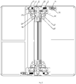
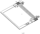
- a hinge of a mobile terminal with a flexible screen the outer side of which supports the flexible screen, comprises a main support body 1 provided with a rotating shaft of the hinge as a biaxial hinge, and the main support body 1 is provided with two rotating shafts of the hinge in parallel, i.e. a first shaft 11 and a second shaft 12.
- the hinge device is provided with a first bracket 21 and a second bracket 22, a first support body 31 and a second support body 32 slidably connected to the first bracket 21 and the second bracket 22 respectively, the first bracket 21 and the first shaft 11 are rotatably connected, the second bracket 22 and the second shaft 12 are rotatably connected.
- Guide grooves 211 and 221 are disposed on the first bracket 21 and the second bracket 22 respectively, the first support body 31 and the second support body 32 are respectively connected with sliders 311, 321 that are slidably connected to the guide grooves 211, 221.
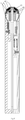
- An auxiliary support body is separately provided between the first support body 31 and the main support body 1 and between the second support body 32 and the main support body 1, and the auxiliary support body is correspondingly located at a bend portion of the hinge in a closed state.
- auxiliary support bodies on each side can be determined according to the thickness of the mobile terminal and the size of the auxiliary support body itself.
- two auxiliary support bodies are used in each side, and they are respectively marked 41, 42, 43, 44.
- the auxiliary support bodies 41, 42 between the first support body 31 and the main support body 1 can rotate around the rotating shaft 11 of the hinge together with the first bracket 21 and self-rotate
- the auxiliary support bodies 43, 44 between the second support body 32 and the main support body 1 can rotate around the rotating shaft 12 of the hinge together with the second bracket 22 and self-rotate
- the axis of the self-rotation is parallel to the rotating shafts 11, 12 of the hinge
- the center of self-rotation is located at or near the flexible screen support reference surface.
- the flexible screen support reference surface is a layer whose length does not change during the opening and closing of the mobile terminal when the hinge is applied to the mobile terminal, which is generally the layer where the flexible screen is located or slightly lower or higher than the layer.
- the hinge is further provided with a first guide structure rotating around the rotating shaft 11 of the hinge together with the first bracket 21 and a second guide structure rotating around the rotating shaft 12 of the hinge together with the second bracket 22;
- the first guide structure may be a guide groove 51 disposed on the first bracket 21, and the second guide structure may be a guide groove 52 disposed on the second bracket 22.
- the auxiliary support bodies 41, 42 between the first support body 31 and the main support body 1 are provided with a structure that is in guiding engagement with the first guide structure, which may be a guide pin that is engaged with the guide groove 51, marked as 411, 421, respectively.
- the auxiliary support bodies 43, 44 between the second support body 32 and the main support body 1 are provided with a structure that is in guiding engagement with the second guide structure, which may be a guide pin that is engaged with the guide groove 52, marked as 431, 441, respectively.
- the above-described guiding engagement further defines the height of the auxiliary support body in the height direction of the hinge (i.e., the direction of the thickness of the mobile terminal), which makes the support height of the bend portion of the hinge, the first support body 31, the second support body 32 on the flexible screen to be consistent, and the actual support of the bend portion of the hinge to conform to the flexible screen support reference surface as much as possible.
- the guide grooves 51 and 52 also limit the end surfaces of the auxiliary support bodies 41, 42, 43, 44, playing a role of limiting the auxiliary support bodies in the direction of the length of the hinge (i.e. the vertical direction of FIG. 2 ).
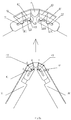
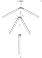
- the foregoing guiding engagement can make the plurality of auxiliary support bodies between the first support body and the main support body and between the second support body and the main support body to rotate in sequence.
- This process is shown in FIG.2a and FIG. 7 , of which, the mark numbers A, B, C, D, E, and F are the centers of rotation.
- a plurality of options is available for the rotation sequence.
- the rotation sequence can be changed by adjusting the guide groove trajectory. Its purpose is to rotate the auxiliary support body in sequence, and facilitate the belt 7 to smoothen the auxiliary support body.
- the first guide structure is provided with a limiting structure for the structure that is in guiding engagement with the first guide structure, such that the relative position of the first guide structure and the structure that is in guiding engagement with the first guide structure is in a stable state when the hinge is in a closed state
- the second guide structure is provided with a limiting structure for the structure that is in guiding engagement with the second guide structure, such that the relative position of the second guide structure and the structure that is in guiding engagement with the second guide structure is in a stable state when the hinge is in a closed state.
- these limiting structures are respectively recesses 53, 54 on the groove wall that are fit with the guide pin.
- the hinge is further provided with a synchronous control mechanism, to allow the first support body and the second support body to rotate synchronously with the rotating shaft of the hinge as an axis.
- the synchronous control mechanism comprises a first swing arm 61 and a second swing arm 62 that are rotatably connected to the rotating shaft of the hinge, the first swing arm 61 and the first shaft 11 are rotatably connected, the second swing arm 62 and the second shaft 12 are rotatably connected, and the first swing arm 61 and the second swing arm 62 are respectively rotatably connected to one end of the first connecting rod 63 and the second connecting rod 64, the rotation axes of the first connecting rod 63 and second connecting rod 64 are perpendicular to the rotating shaft of the hinge, and the other ends of the first connecting rod 63 and the second connecting rod 64 are respectively rotatably connected to the first support body 31 and the second support body 32.
- the synchronous control mechanism is located inside of the flexible screen support reference surface and is not in the same plane as the flexible screen support reference surface.
- the hinge is further provided with a belt 7 that is an elastic belt or a flexible belt or a belt that is tensioned by an elastic member or a flexible member.
- the belt may be composed of one or more metal spring wires, fibers (nylon, aramid, polyester, etc.), or metal or fiber strips, or may be tensioned by spring 71 at the ends.
- One end of the belt 7 is fixedly connected by one of the first support body and the second support body through the connector 73, and the connector 72 at the other end is tightened by the spring 71 supported on the other of the first support body and the second support body. Both ends of the belt can be combined by means of compression, welding with the connector or bonding with glue.
- the belt passes from the auxiliary support bodies 41, 42, 43, 44 and the main support body 1 or a component fixedly connected thereto from a path intersecting with the rotating shaft of the hinge, which may produce pressure on these components to smoothen the auxiliary support bodies 41, 42, 43, 44 in the rotation process and in the stop state, to avoid the unevenness of support caused by the deviation of the rotation angle and direction of the different auxiliary support bodies, so that the auxiliary support bodies 41, 42, 43 and 44 together with the main support body 1 can provide a flat support for the flexible screen whether in an open state or closed state of the hinge or during the rotation.
- the outer side of the auxiliary support body and the main support body are provided with a groove 40, the belt 7 passes through a path defined by the groove 40, and a plate 45 is connected to the notch of the groove 40.
- the first support body and the second support body also have corresponding grooves 40 and plates 45.
- the belt 7 is arranged therein, which is slightly slid by the pulling of one end of the elastic part or slightly deformed by the fitting between the elastic force and the rotating component during the opening or closing of the hinge.
- the inner side of the first support body 31 and the inner side of the second support body 32 are further connected with covers 33, 34 for shielding the hinge structure.
- two hinges are integrated to a hinge device of a mobile terminal, the axes of the rotating shafts 11, 12 of the two hinges are one-to-one coincident, the first support bodies 31 of the two hinges are integrated and the second support bodies 32 of the two hinges are also integrated, the main support bodies 1 of the two hinges are also integrated.
- the auxiliary support bodies between the first support body 31 and the main support body 1 of two hinges have the same number and are one-to-one connected together.
- the auxiliary support bodies between the second support body 32 and the main support body 1 of two hinges have the same number and are one-to-one connected together.
- a torque mechanism can also be arranged on the rotating shaft of the hinge to provide a rotational resistance by providing a frictional force, so as to stop and position at any time.
- the torque mechanism can be disposed at any part that is rotatably or slidably connected to the rotating shaft of the hinge in the figure.
- the mobile terminal with a flexible screen provided in the present invention may be a mobile phone or a computer, etc., which may be folded in a book form.
- the mobile terminal with a flexible screen is provided with the above-mentioned hinge device and the flexible screen 100, and the flexible screen is disposed at the outside of the mobile terminal with a flexible screen.
- the first support body, second support body, main support body, and auxiliary support body form a support for the flexible screen.
- a hinge of a mobile terminal with a flexible screen the outer side of which supports the flexible screen, comprises a main support body 1 provided with a rotating shaft of the hinge as a biaxial hinge, and the main support body 1 is provided with two rotating shafts of the hinge in parallel, i.e. a first shaft 11 and a second shaft 12.
- the hinge device is provided with a first bracket 21 and a second bracket 22, a first support body 31 and a second support body 32 slidably connected to the first bracket 21 and the second bracket 22 respectively, the first bracket 21 and the first shaft 11 are rotatably connected, the second bracket 22 and the second shaft 12 are rotatably connected.
- Guide grooves 211 and 221 are disposed on the first bracket 21 and the second bracket 22 respectively, the first support body 31 and the second support body 32 are respectively connected with sliders 311, 321 that are slidably connected to the guide grooves 211, 221.
- the sliders 311, 321 are respectively provided with recesses 312, 322
- the first bracket 21 and the second bracket 22 are provided with clamp springs 212, 222
- the clamp springs 212, 222 are provided with convex portions 213, 223 that fit with the recesses 312, 322.
- the recesses are fit with the convex portions, to provide hand feeling when the hinge is opened and closed appropriately.
- An auxiliary support body is separately provided between the first support body 31 and the main support body 1 and between the second support body 32 and the main support body 1, and the auxiliary support body is correspondingly located at a bend portion of the hinge in a closed state.
- auxiliary support bodies on each side can be determined according to the thickness of the mobile terminal and the size of the auxiliary support body itself.
- two auxiliary support bodies are used in each side, and they are respectively marked 41, 42, 43, 44.
- the auxiliary support bodies 41, 42 between the first support body 31 and the main support body 1 can rotate around the rotating shaft 11 of the hinge together with the first bracket 21 and self-rotate
- the auxiliary support bodies 43, 44 between the second support body 32 and the main support body 1 can rotate around the rotating shaft 12 of the hinge together with the second bracket 22 and self-rotate
- the axis of the self-rotation is parallel to the rotating shafts 11, 12 of the hinge
- the center of self-rotation is located at or near the flexible screen support reference surface.
- the flexible screen support reference surface is a layer whose length does not change during the opening and closing of the mobile terminal when the hinge is applied to the mobile terminal, which is generally the layer where the flexible screen is located or slightly lower or higher than the layer.
- the hinge is further provided with a first guide structure rotating around the rotating shaft 11 of the hinge together with the first bracket 21 and a second guide structure rotating around the rotating shaft 12 of the hinge together with the second bracket 22;
- the first guide structure may be a guide groove 51 disposed on the first bracket 21, and the second guide structure may be a guide groove 52 disposed on the second bracket 22.
- the auxiliary support bodies 41, 42 between the first support body 31 and the main support body 1 are provided with a structure that is in guiding engagement with the first guide structure, which may be a guide pin that is engaged with the guide groove 51, marked as 411, 421, respectively.
- the auxiliary support bodies 43, 44 between the second support body 32 and the main support body 1 are provided with a structure that is in guiding engagement with the second guide structure, which may be a guide pin that is engaged with the guide groove 52, marked as 431, 441, respectively.
- the above-described guiding engagement further defines the height of the auxiliary support body in the height direction of the hinge (i.e., the direction of the thickness of the mobile terminal), which makes the support height of the bend portion of the hinge, the first support body 31, the second support body 32 on the flexible screen to be consistent, and the actual support of the bend portion of the hinge to conform to the flexible screen support reference surface as much as possible.
- the guide grooves 51 and 52 also limit the end surfaces of the auxiliary support bodies 41, 42, 43, 44, playing a role of limiting the auxiliary support bodies in the direction of the length of the hinge.
- the foregoing guiding engagement can make the plurality of auxiliary support bodies between the first support body and the main support body and between the second support body and the main support body to rotate in sequence.
- This process is shown in FIG.2a and FIG. 7 , of which, the mark numbers A, B, C, D, E, and F are the centers of rotation.
- a plurality of options is available for the rotation sequence.
- the rotation sequence can be changed by adjusting the guide groove trajectory. Its purpose is to rotate the auxiliary support body in sequence, and facilitate the sheet 700 to smoothen the auxiliary support body.
- the first guide structure is provided with a limiting structure for the structure that is in guiding engagement with the first guide structure, such that the relative position of the first guide structure and the structure that is in guiding engagement with the first guide structure is in a stable state when the hinge is in a closed state
- the second guide structure is provided with a limiting structure for the structure that is in guiding engagement with the second guide structure, such that the relative position of the second guide structure and the structure that is in guiding engagement with the second guide structure is in a stable state when the hinge is in a closed state.
- These limiting structures are respectively recesses 53, 54 on the groove wall that are fit with the guide pin.
- the hinge is further provided with a synchronous control mechanism, to allow the first support body and the second support body to rotate synchronously with the rotating shaft of the hinge as an axis.
- the synchronous control mechanism comprises a first swing arm 61 and a second swing arm 62 that are rotatably connected to the rotating shaft of the hinge, the first swing arm 61 and the first shaft 11 are rotatably connected, the second swing arm 62 and the second shaft 12 are rotatably connected, and the first swing arm 61 and the second swing arm 62 are respectively rotatably connected to one end of the first connecting rod 63 and the second connecting rod 64, the rotation axes of the first connecting rod 63 and second connecting rod 64 are perpendicular to the rotating shaft of the hinge, and the other ends of the first connecting rod 63 and the second connecting rod 64 are respectively rotatably connected to the first support body 31 and the second support body 32.
- the synchronous control mechanism is located inside of the flexible screen support reference surface and is not in the same plane as the flexible screen support reference surface.
- the hinge is further provided with a sheet 700 that can be repeatedly bent.
- the sheet 700 may be a steel strip, a memory alloy strip, a woven fabric strip, a metal ribbon, etc.
- the sheet is located at the upper surface near the ends of the auxiliary support bodies 41, 42, 43 and 44 and the main support body 1, and the two ends of the sheet 700 are respectively connected to the first support body 31 and the second support body 32.
- the sheet 700 may be connected by welding, glue bonding, riveting, etc.
- the sheet 700 is located at or close to the flexible screen support reference surface.
- the first support body 31 and the second support body 32 may be respectively provided with a concave portion to connect with the sheet 700.
- the concave portions are respectively provided with connecting bases 333, 334 of the stepped surfaces. Both ends of the sheet 700 are located at the stepped surfaces 334, 344, so that the sheet 700 is located at or close to the flexible screen support reference surface while maintaining the design of thinning of the hinge.
- the sheet 700 may be of the uniform thickness. As shown in FIGS. 14 , 15 , 16 , 18, 19, 20 , the sheets may also be inconsistent in thickness.
- the thick parts (A1, A2, A3, A4, A5, A6, A7) are connected to the main support body, the auxiliary support body, the first support body 31 and the second support body 32 to enhance the connection strength, while the thin parts (A8, A9, A10, A11, A12, A13) are deformed, to increase the number of life times during bending.
- the sheet 700 may smoothen the auxiliary support bodies 41, 42, 43, 44 in the rotation process and in the stop state, to avoid the unevenness of support caused by the deviation of the rotation angle and direction of the different auxiliary support bodies, so that the auxiliary support bodies 41, 42, 43 and 44 together with the main support body 1 can provide a flat support for the flexible screen whether in an open state or closed state of the hinge or during the rotation.
- the inner side of the first support body 31 and the inner side of the second support body 32 are further connected with covers 331, 341, and the inner side of the first bracket 21 and the inner side of the second bracket 22 are also connected with covers 332, 342, the cover 331 has an overlapping portion with the cover 332, and the cover 332 has an overlapping portion with the cover 342 for shielding the above hinge structure.
- two hinges are integrated to a hinge device of a mobile terminal, the axes of the rotating shafts 11, 12 of the two hinges are one-to-one coincident, the first support bodies 31 of the two hinges are integrated and the second support bodies 32 of the two hinges are also integrated, the main support bodies 1 of the two hinges are also integrated.
- the auxiliary support bodies between the first support body 31 and the main support body 1 of two hinges have the same number and are one-to-one connected together.
- the auxiliary support bodies between the second support body 32 and the main support body 1 of two hinges have the same number and are one-to-one connected together.
- a torque mechanism can also be arranged on the rotating shaft of the hinge to provide a rotational resistance by providing a frictional force, so as to stop and position at any time.
- the torque mechanism can be disposed at any part that is rotatably or slidably connected to the rotating shaft of the hinge in the figure.
- the mobile terminal with a flexible screen provided in the present invention may be a mobile phone or a computer, etc., which may be folded in a book form.
- the mobile terminal with a flexible screen is provided with the above-mentioned hinge device and the flexible screen 100, and the flexible screen is disposed at the outside of the mobile terminal with a flexible screen.
- the first support body, second support body, main support body, and auxiliary support body form a support for the flexible screen.
Landscapes
- Engineering & Computer Science (AREA)
- General Engineering & Computer Science (AREA)
- Computer Hardware Design (AREA)
- Theoretical Computer Science (AREA)
- Signal Processing (AREA)
- Human Computer Interaction (AREA)
- Physics & Mathematics (AREA)
- General Physics & Mathematics (AREA)
- Mechanical Engineering (AREA)
- Telephone Set Structure (AREA)
- Pivots And Pivotal Connections (AREA)
Applications Claiming Priority (2)
| Application Number | Priority Date | Filing Date | Title |
|---|---|---|---|
| CN201620544672.3U CN205847346U (zh) | 2016-06-07 | 2016-06-07 | 一种柔性屏移动终端的铰链、铰链装置及柔性屏移动终端 |
| PCT/CN2017/079567 WO2017211115A1 (zh) | 2016-06-07 | 2017-04-06 | 一种柔性屏移动终端的铰链、铰链装置及柔性屏移动终端 |
Publications (3)
| Publication Number | Publication Date |
|---|---|
| EP3467325A1 true EP3467325A1 (de) | 2019-04-10 |
| EP3467325A4 EP3467325A4 (de) | 2020-01-29 |
| EP3467325B1 EP3467325B1 (de) | 2020-11-11 |
Family
ID=57622988
Family Applications (1)
| Application Number | Title | Priority Date | Filing Date |
|---|---|---|---|
| EP17809555.0A Active EP3467325B1 (de) | 2016-06-07 | 2017-04-06 | Scharnier und scharniervorrichtung eines mobilen endgeräts mit einem flexiblen bildschirm und mobiles endgerät mit einem flexiblen bildschirm |
Country Status (6)
| Country | Link |
|---|---|
| US (1) | US10627867B2 (de) |
| EP (1) | EP3467325B1 (de) |
| JP (1) | JP6752538B2 (de) |
| KR (1) | KR102104740B1 (de) |
| CN (1) | CN205847346U (de) |
| WO (1) | WO2017211115A1 (de) |
Cited By (13)
| Publication number | Priority date | Publication date | Assignee | Title |
|---|---|---|---|---|
| CN110445913A (zh) * | 2019-07-31 | 2019-11-12 | 华为技术有限公司 | 折叠组件及电子设备 |
| CN111043149A (zh) * | 2019-12-20 | 2020-04-21 | 深圳市长盈精密技术股份有限公司 | 折叠铰链及折叠显示装置 |
| TWI693352B (zh) * | 2019-06-25 | 2020-05-11 | 富世達股份有限公司 | 折疊式螢幕裝置及鉸鏈機構 |
| EP3627805A4 (de) * | 2017-05-17 | 2020-05-27 | Guangdong Oppo Mobile Telecommunications Corp., Ltd. | Faltbares mobiles endgerät |
| EP3627804A4 (de) * | 2017-05-17 | 2020-05-27 | Guangdong Oppo Mobile Telecommunications Corp., Ltd. | Klappmechanismus, klappmechanismusanordnung und klappbares mobiles endgerät |
| EP3627802A4 (de) * | 2017-05-17 | 2020-05-27 | Guangdong Oppo Mobile Telecommunications Corp., Ltd. | Faltbares mobiles endgerät |
| EP3637741A4 (de) * | 2017-05-17 | 2020-05-27 | Guangdong Oppo Mobile Telecommunications Corp., Ltd. | Faltbares mobiles endgerät |
| EP3624430A4 (de) * | 2017-05-17 | 2020-05-27 | Guangdong Oppo Mobile Telecommunications Corp., Ltd. | Faltbares mobiles endgerät |
| EP3637742A4 (de) * | 2017-06-06 | 2021-03-17 | Hangzhou Amphenol Phoenix Telecom Parts Co., Ltd. | Scharnier eines mobilen endgeräts mit flexiblem bildschirm und mobiles endgerät mit flexiblem bildschirm |
| US11042193B2 (en) | 2017-05-17 | 2021-06-22 | Guangdong Oppo Mobile Telecommunications Corp., Ltd. | Foldable mobile terminal, foldable mechanism for foldable mobile terminal, and foldable unit for foldable mobile terminal |
| CN113163037A (zh) * | 2021-04-25 | 2021-07-23 | 苏州宝卓智能科技有限公司 | 一种稳定性高强度手机折叠屏 |
| EP4036683A4 (de) * | 2019-10-22 | 2022-12-21 | Huawei Technologies Co., Ltd. | Klappbares bauteil und klappbares anzeigeendgerät |
| US11614780B2 (en) | 2019-02-19 | 2023-03-28 | Samsung Electronics Co., Ltd. | Hinge module and foldable electronic device including the same |
Families Citing this family (108)
| Publication number | Priority date | Publication date | Assignee | Title |
|---|---|---|---|---|
| CN205847346U (zh) | 2016-06-07 | 2016-12-28 | 杭州安费诺飞凤通信部品有限公司 | 一种柔性屏移动终端的铰链、铰链装置及柔性屏移动终端 |
| CN106873717B (zh) * | 2017-02-06 | 2019-11-26 | 武汉华星光电技术有限公司 | 柔性显示模组及具有该柔性显示模组的电子装置 |
| CN207200775U (zh) * | 2017-04-06 | 2018-04-06 | 杭州安费诺飞凤通信部品有限公司 | 柔性屏移动终端的铰链、铰链装置及柔性屏移动终端 |
| CN206918043U (zh) | 2017-04-19 | 2018-01-23 | 广东欧珀移动通信有限公司 | 转轴组件及可折叠终端 |
| KR102426694B1 (ko) | 2017-05-02 | 2022-07-29 | 삼성전자주식회사 | 플렉서블 디스플레이를 포함하는 전자 장치 |
| CN108965501A (zh) * | 2017-05-17 | 2018-12-07 | 广东欧珀移动通信有限公司 | 可折叠移动终端 |
| CN108965500A (zh) * | 2017-05-17 | 2018-12-07 | 广东欧珀移动通信有限公司 | 折叠机构、折叠机构组件及可折叠移动终端 |
| CN108965502B (zh) * | 2017-05-17 | 2024-02-20 | Oppo广东移动通信有限公司 | 可折叠移动终端 |
| CN108965503B (zh) * | 2017-05-17 | 2024-04-16 | Oppo广东移动通信有限公司 | 可折叠移动终端 |
| KR101834793B1 (ko) * | 2017-07-28 | 2018-03-06 | 엘지디스플레이 주식회사 | 플렉서블 디스플레이 및 이를 포함하는 전자 장치 |
| CN109404411B (zh) * | 2017-08-15 | 2020-06-16 | 深圳市富世达通讯有限公司 | 软性显示设备、支撑装置及双轴式枢纽模块 |
| CN207543155U (zh) * | 2017-11-03 | 2018-06-26 | 杭州安费诺飞凤通信部品有限公司 | 内柔性屏移动终端的铰链及内柔性屏移动终端 |
| CN107831836A (zh) * | 2017-11-27 | 2018-03-23 | 努比亚技术有限公司 | 一种用于柔性屏的折叠机构 |
| CN109936648B (zh) | 2017-12-18 | 2020-08-07 | 华为技术有限公司 | 转动机构及折叠终端 |
| CN108271324B (zh) * | 2017-12-20 | 2024-04-26 | 广东长盈精密技术有限公司 | 壳体以及移动终端 |
| KR102524651B1 (ko) * | 2017-12-29 | 2023-04-21 | 삼성디스플레이 주식회사 | 폴더블 표시 장치 |
| CN208190691U (zh) * | 2018-01-08 | 2018-12-04 | 杭州安费诺飞凤通信部品有限公司 | 半自动内折柔性屏移动终端铰链及内折柔性屏移动终端 |
| KR20190084836A (ko) * | 2018-01-09 | 2019-07-17 | (주)오라컴디스플레이 | 폴더블 디스플레이장치용 힌지 |
| CN207975120U (zh) * | 2018-01-16 | 2018-10-16 | 杭州安费诺飞凤通信部品有限公司 | 一种外柔性屏移动终端的铰链和铰链装置 |
| KR102537378B1 (ko) * | 2018-01-30 | 2023-05-26 | 삼성디스플레이 주식회사 | 폴더블 표시 장치 |
| CN108322567B (zh) * | 2018-02-01 | 2019-11-08 | 杭州安费诺飞凤通信部品有限公司 | 一种内折柔性屏移动终端的铰链及内折柔性屏移动终端 |
| WO2019174249A1 (zh) * | 2018-03-12 | 2019-09-19 | 深圳市柔宇科技有限公司 | 弯折机构与柔性显示装置 |
| WO2019174223A1 (zh) * | 2018-03-12 | 2019-09-19 | 深圳市柔宇科技有限公司 | 铰链装置、壳体及电子装置 |
| EP3767611A1 (de) * | 2018-03-12 | 2021-01-20 | Shenzhen Royole Technologies Co., Ltd | Faltkomponente und flexible anzeigevorrichtung |
| US10296048B1 (en) * | 2018-03-14 | 2019-05-21 | Htc Corporation | Portable electronic device with dual displays and a hinge structure |
| WO2019210766A1 (en) | 2018-05-02 | 2019-11-07 | Guangdong Oppo Mobile Telecommunications Corp., Ltd. | Foldable screen assembly and electronic device |
| CN110445890A (zh) * | 2018-05-02 | 2019-11-12 | Oppo广东移动通信有限公司 | 可折叠屏组件及电子装置 |
| TWI674497B (zh) * | 2018-05-04 | 2019-10-11 | 仁寶電腦工業股份有限公司 | 樞轉機構與電子裝置 |
| CN108712529B (zh) * | 2018-05-24 | 2020-10-23 | 维沃移动通信有限公司 | 一种铰链和移动终端 |
| WO2019223013A1 (zh) * | 2018-05-25 | 2019-11-28 | 深圳市柔宇科技有限公司 | 可弯曲机构、可弯曲显示模组及可弯曲终端 |
| CN112513773A (zh) * | 2018-05-25 | 2021-03-16 | 深圳市柔宇科技股份有限公司 | 一种框架模组及可弯曲终端 |
| CN108738258B (zh) * | 2018-05-28 | 2019-11-15 | 武汉华星光电半导体显示技术有限公司 | 可弯折的移动终端 |
| WO2019238000A1 (zh) * | 2018-06-14 | 2019-12-19 | 杭州安费诺飞凤通信部品有限公司 | 柔性屏移动终端铰链及柔性屏移动终端 |
| WO2019237337A1 (zh) * | 2018-06-15 | 2019-12-19 | 深圳市柔宇科技有限公司 | 电子装置及其柔性屏支撑机构 |
| TWI673545B (zh) * | 2018-06-21 | 2019-10-01 | 兆利科技工業股份有限公司 | 折疊式裝置的轉軸模組 |
| KR102512482B1 (ko) | 2018-07-31 | 2023-03-21 | 엘지디스플레이 주식회사 | 폴더블 디스플레이 |
| US11256304B2 (en) * | 2018-08-31 | 2022-02-22 | Hewlett-Packard Development Company, L.P. | Suspensions for displays |
| CN109210071B (zh) * | 2018-09-13 | 2020-09-29 | 维沃移动通信有限公司 | 移动终端及铰链机构 |
| CN208673636U (zh) * | 2018-09-19 | 2019-03-29 | 云谷(固安)科技有限公司 | 一种屏体支撑装置以及可折叠式柔性显示装置 |
| CN108999882A (zh) * | 2018-10-10 | 2018-12-14 | 东莞市劲丰电子有限公司 | 一种柔性屏应用的同轴190度外折转动机构 |
| US10782739B2 (en) * | 2018-10-29 | 2020-09-22 | Google Llc | Electronic device with flexible display |
| CN109600465A (zh) * | 2018-12-05 | 2019-04-09 | 邹耿彪 | 一种折扇形状的移动通信终端 |
| TWI709025B (zh) * | 2018-12-25 | 2020-11-01 | 仁寶電腦工業股份有限公司 | 電子裝置 |
| TWI791137B (zh) * | 2019-01-18 | 2023-02-01 | 仁寶電腦工業股份有限公司 | 電子裝置 |
| CN109688251A (zh) * | 2019-01-26 | 2019-04-26 | 东莞市劲丰电子有限公司 | 全贴合应用的两轴外折下部齿条转动机构 |
| US10993338B2 (en) | 2019-01-31 | 2021-04-27 | Lg Electronics Inc. | Flexible display device |
| US10820433B2 (en) | 2019-01-31 | 2020-10-27 | Lg Electronics Inc. | Flexible display device |
| US11003217B2 (en) | 2019-01-31 | 2021-05-11 | Lg Electronics Inc. | Flexible display device |
| WO2020159097A1 (en) * | 2019-01-31 | 2020-08-06 | Lg Electronics Inc. | Flexible display device |
| CN109862156B (zh) * | 2019-02-22 | 2020-06-26 | 华为技术有限公司 | 一种支撑组件及移动终端 |
| CN109830185B (zh) * | 2019-02-22 | 2024-05-17 | 华为技术有限公司 | 一种折叠组件、折叠显示终端 |
| CN111614800B (zh) * | 2019-02-23 | 2021-10-01 | 华为技术有限公司 | 一种移动终端 |
| CN114519960B (zh) * | 2019-02-25 | 2024-04-02 | Oppo广东移动通信有限公司 | 转动装置、壳体及电子装置 |
| KR102181791B1 (ko) * | 2019-03-14 | 2020-11-27 | 주식회사 아밀이엔지 | 폴더블폰용 힌지장치 |
| CN111698355B (zh) * | 2019-03-15 | 2021-07-09 | 华为技术有限公司 | 一种转轴机构及移动终端 |
| KR20200125887A (ko) * | 2019-04-28 | 2020-11-05 | (주)에이유플렉스 | 폴더블 디바이스용 폴딩힌지 |
| WO2020246811A1 (ko) * | 2019-06-03 | 2020-12-10 | (주)에이유플렉스 | 탄성구동체 |
| CN112153178A (zh) * | 2019-06-27 | 2020-12-29 | 华为技术有限公司 | 一种转轴机构及可折叠移动终端 |
| KR20210150583A (ko) * | 2019-07-04 | 2021-12-10 | 엘지전자 주식회사 | 이동 단말기 |
| CN110197624B (zh) * | 2019-07-09 | 2021-04-09 | 京东方科技集团股份有限公司 | 可折叠组件和可折叠显示装置 |
| CN110273916A (zh) * | 2019-07-12 | 2019-09-24 | 东莞市劲丰电子有限公司 | 基于两轴转五轴的柔性屏外折同步转动机构 |
| CN112399735A (zh) * | 2019-08-18 | 2021-02-23 | 深圳市柔宇科技有限公司 | 折叠装置及电子设备 |
| CN113366927A (zh) * | 2019-07-15 | 2021-09-07 | 深圳市柔宇科技股份有限公司 | 折叠装置及电子设备 |
| CN110259816A (zh) * | 2019-07-16 | 2019-09-20 | 东莞市劲丰电子有限公司 | 满足柔性屏外折的单轴式铰链组合机构 |
| CN113383380A (zh) * | 2019-07-26 | 2021-09-10 | 深圳市柔宇科技股份有限公司 | 一种弯折装置和柔性装置 |
| WO2021020631A1 (ko) * | 2019-08-01 | 2021-02-04 | 엘지전자 주식회사 | 이동 단말기 |
| CN110730257A (zh) * | 2019-08-26 | 2020-01-24 | 深圳市长盈精密技术股份有限公司 | 固定装置、折叠铰链及折叠显示装置 |
| CN110425217A (zh) * | 2019-08-28 | 2019-11-08 | 东莞市劲丰电子有限公司 | 基于齿轮齿条同步的两轴外折转动机构 |
| US20200029449A1 (en) * | 2019-09-27 | 2020-01-23 | Intel Corporation | Flexible chassis for a flexible display |
| KR102657947B1 (ko) * | 2019-10-18 | 2024-04-17 | 삼성전자주식회사 | 방진 구조를 가지는 폴더블 전자 장치 |
| KR20210047389A (ko) * | 2019-10-21 | 2021-04-30 | 삼성디스플레이 주식회사 | 표시 장치 |
| CN112769978B (zh) | 2019-11-01 | 2022-11-18 | 杭州安费诺飞凤通信部品有限公司 | 一种外柔性屏移动电子终端及其铰链组件 |
| CN110782791B (zh) * | 2019-11-06 | 2024-05-07 | 东莞市环力智能科技有限公司 | 一种带折叠铰链组件的移动终端 |
| TWI711365B (zh) * | 2019-11-14 | 2020-11-21 | 宏碁股份有限公司 | 轉軸模組與可攜式電子裝置 |
| CN112995368B (zh) | 2019-12-13 | 2021-12-21 | 华为技术有限公司 | 一种铰链和移动终端 |
| CN110778600A (zh) * | 2019-12-17 | 2020-02-11 | 东莞市中科冠腾科技股份有限公司 | 一种双向折叠铰链机构 |
| CN113014696B (zh) * | 2019-12-20 | 2023-08-01 | 中兴通讯股份有限公司 | 折叠终端结构 |
| US10932381B1 (en) * | 2019-12-31 | 2021-02-23 | Wuhan China Star Optoelectronics Semiconductor Display Technology Co., Ltd. | Display panel support frame and display device |
| WO2021140401A1 (ja) * | 2020-01-10 | 2021-07-15 | 株式会社半導体エネルギー研究所 | 角度調整装置、支持具および表示装置 |
| TWI780569B (zh) * | 2020-01-20 | 2022-10-11 | 仁寶電腦工業股份有限公司 | 折疊式電子裝置 |
| KR102250762B1 (ko) * | 2020-02-06 | 2021-05-10 | 윤남호 | 자동힌지구조를 구비한 접이식 구조물 |
| CN113434010B (zh) * | 2020-03-23 | 2023-05-30 | 宏碁股份有限公司 | 折叠式屏幕与可携式电子装置 |
| CN111405095A (zh) * | 2020-03-30 | 2020-07-10 | 维沃移动通信有限公司 | 折叠机构及电子设备 |
| US11435785B2 (en) * | 2020-04-22 | 2022-09-06 | Eum, Inc. | Foldable display device |
| CN113803575A (zh) * | 2020-06-12 | 2021-12-17 | 中兴通讯股份有限公司 | 一种柔性屏支撑装置及智能终端 |
| KR102298726B1 (ko) * | 2020-06-24 | 2021-09-07 | 주식회사 하이맥 | 휴대단말기용 폴더블 힌지모듈 |
| KR20220006189A (ko) * | 2020-07-08 | 2022-01-17 | 삼성전자주식회사 | 디스플레이 보호 구조를 포함하는 폴더블 전자 장치 |
| CN114079679B (zh) * | 2020-08-17 | 2023-02-03 | 华为技术有限公司 | 可折叠电子设备 |
| KR20220030668A (ko) * | 2020-09-03 | 2022-03-11 | 삼성전자주식회사 | 장력 유지 구조를 갖는 전자 장치 |
| CN114338861A (zh) * | 2020-09-29 | 2022-04-12 | 华为技术有限公司 | 折叠装置及电子设备 |
| CN112145544B (zh) * | 2020-09-29 | 2023-02-21 | 重庆大学 | 串联结构的固定旋转中心多轴全柔性铰链 |
| TWI768530B (zh) * | 2020-11-04 | 2022-06-21 | 富世達股份有限公司 | 鉸鏈 |
| CN112253611A (zh) * | 2020-11-07 | 2021-01-22 | 东莞市劲丰电子有限公司 | 双连杆旋转的u型内折转动机构 |
| EP4184902A4 (de) | 2020-12-18 | 2024-02-28 | Samsung Electronics Co Ltd | Scharniermodul und elektronische vorrichtung damit |
| CN112696426B (zh) * | 2020-12-22 | 2022-03-11 | 维沃移动通信有限公司 | 铰链机构、折叠机构及电子设备 |
| KR20220093624A (ko) * | 2020-12-28 | 2022-07-05 | 엘지디스플레이 주식회사 | 폴더블 표시 장치 |
| JP2022112403A (ja) * | 2021-01-21 | 2022-08-02 | 株式会社Joled | 表示装置 |
| US11971756B2 (en) | 2021-01-27 | 2024-04-30 | Samsung Electronics Co., Ltd. | Electronic device including flexible display |
| KR20220108506A (ko) * | 2021-01-27 | 2022-08-03 | 삼성전자주식회사 | 플렉서블 디스플레이를 포함하는 전자 장치 |
| US11385687B1 (en) | 2021-01-29 | 2022-07-12 | Samsung Electronics Co., Ltd. | Hinge structure and electronic device including the same |
| CN115136574B (zh) * | 2021-01-29 | 2024-04-30 | 三星电子株式会社 | 铰链结构和包括铰链结构的电子装置 |
| CN215861291U (zh) * | 2021-06-29 | 2022-02-18 | 杭州安费诺飞凤通信部品有限公司 | 一种铰链及内折柔性屏移动终端 |
| KR20230040132A (ko) * | 2021-09-15 | 2023-03-22 | 삼성전자주식회사 | 전기물을 전기적으로 연결하는 연결 부재를 포함하는 폴더블 전자 장치 |
| KR20230044644A (ko) * | 2021-09-27 | 2023-04-04 | 삼성전자주식회사 | 힌지 어셈블리 및 이를 포함하는 전자 장치 |
| CN116391084A (zh) * | 2021-10-25 | 2023-07-04 | 京东方科技集团股份有限公司 | 支撑结构和显示装置 |
| CN117905783A (zh) * | 2022-10-17 | 2024-04-19 | 华为技术有限公司 | 一种可折叠的电子设备及其转轴机构 |
| CN117119088A (zh) * | 2023-04-21 | 2023-11-24 | 荣耀终端有限公司 | 一种可折叠式移动终端 |
| CN117420890B (zh) * | 2023-12-19 | 2024-03-15 | 合肥联宝信息技术有限公司 | 一种屏幕外折叠的笔记本电脑的转轴套件 |
Family Cites Families (19)
| Publication number | Priority date | Publication date | Assignee | Title |
|---|---|---|---|---|
| US6253419B1 (en) * | 2000-01-13 | 2001-07-03 | Lu Sheng-Nan | Pivot device with multiple pivotal bars for a notebook computer |
| ES2364270T3 (es) * | 2003-08-05 | 2011-08-30 | Llaza, S.A. | Brazo articulado para toldo, con efecto elástico mejorado. |
| JP4111957B2 (ja) * | 2004-04-09 | 2008-07-02 | フェニックス コリア 株式会社 | 回転して広げられたり折り畳まれたりできる二つのユニットを備える携帯装置及びその携帯装置に使用されるヒンジ装置 |
| TWM294822U (en) * | 2006-03-01 | 2006-07-21 | Quanta Comp Inc | Hinge apparatus and computer device |
| KR101218683B1 (ko) * | 2006-08-28 | 2013-01-18 | 엘지전자 주식회사 | 헤드 부상구조를 갖는 힌지 조립체와 이를 구비한 휴대단말기 |
| KR20100079459A (ko) * | 2008-12-31 | 2010-07-08 | (주)엘티엠에이피 | 폴더타입 휴대통신장치용 힌지조립체 |
| KR101061760B1 (ko) * | 2010-01-29 | 2011-09-02 | 주식회사 케이에이치바텍 | 휴대단말기용 스윙타입 힌지모듈 |
| CN102619866A (zh) * | 2011-01-28 | 2012-08-01 | 鸿富锦精密工业(深圳)有限公司 | 铰链结构 |
| US9176535B2 (en) * | 2011-06-03 | 2015-11-03 | Microsoft Technology Licensing, Llc | Flexible display flexure assembly |
| US8971032B2 (en) * | 2012-11-02 | 2015-03-03 | Blackberry Limited | Support for a flexible display |
| KR102034585B1 (ko) * | 2013-07-09 | 2019-10-21 | 엘지전자 주식회사 | 디스플레이 장치 |
| KR101547640B1 (ko) * | 2013-09-16 | 2015-08-27 | (주) 프렉코 | 가이드부재를 갖는 플렉시블 디스플레이장치 |
| CN104613089B (zh) * | 2013-11-05 | 2017-04-12 | 昆山万禾精密电子有限公司 | 稳定开合的双轴铰链 |
| WO2015093801A1 (ko) * | 2013-12-16 | 2015-06-25 | 주식회사 세네카 | 플렉시블 디스플레이장치용 힌지모듈 |
| WO2015163272A1 (ja) * | 2014-04-24 | 2015-10-29 | シャープ株式会社 | 表示装置 |
| KR102202228B1 (ko) * | 2014-06-11 | 2021-01-13 | 삼성전자 주식회사 | 플렉서블 디스플레이를 포함하는 전자 장치 |
| KR101706321B1 (ko) * | 2014-11-19 | 2017-03-13 | 주식회사 세네카 | 힌지 장치 |
| CN105065431B (zh) * | 2015-07-20 | 2017-12-29 | 联想(北京)有限公司 | 一种电子设备和柔性连接装置 |
| CN205847346U (zh) * | 2016-06-07 | 2016-12-28 | 杭州安费诺飞凤通信部品有限公司 | 一种柔性屏移动终端的铰链、铰链装置及柔性屏移动终端 |
-
2016
- 2016-06-07 CN CN201620544672.3U patent/CN205847346U/zh active Active
-
2017
- 2017-04-06 JP JP2018564276A patent/JP6752538B2/ja not_active Expired - Fee Related
- 2017-04-06 US US16/308,000 patent/US10627867B2/en active Active
- 2017-04-06 EP EP17809555.0A patent/EP3467325B1/de active Active
- 2017-04-06 KR KR1020187038092A patent/KR102104740B1/ko active IP Right Grant
- 2017-04-06 WO PCT/CN2017/079567 patent/WO2017211115A1/zh unknown
Cited By (21)
| Publication number | Priority date | Publication date | Assignee | Title |
|---|---|---|---|---|
| US11042193B2 (en) | 2017-05-17 | 2021-06-22 | Guangdong Oppo Mobile Telecommunications Corp., Ltd. | Foldable mobile terminal, foldable mechanism for foldable mobile terminal, and foldable unit for foldable mobile terminal |
| EP3627804A4 (de) * | 2017-05-17 | 2020-05-27 | Guangdong Oppo Mobile Telecommunications Corp., Ltd. | Klappmechanismus, klappmechanismusanordnung und klappbares mobiles endgerät |
| EP3627803B1 (de) * | 2017-05-17 | 2023-08-16 | Guangdong Oppo Mobile Telecommunications Corp., Ltd. | Faltbares mobiles endgerät |
| US11175695B2 (en) | 2017-05-17 | 2021-11-16 | Guangdong Oppo Mobile Telecommunications Corp., Ltd. | Foldable mobile terminal, foldable mechanism for foldable mobile terminal, and foldable unit for foldable mobile terminal |
| US11061443B2 (en) | 2017-05-17 | 2021-07-13 | Guangdong Oppo Mobile Telecommunications Corp., Ltd. | Foldable mechanism for foldable mobile terminal, foldable mechanism assembly for foldable mobile terminal, and foldable mobile terminal |
| EP3627802A4 (de) * | 2017-05-17 | 2020-05-27 | Guangdong Oppo Mobile Telecommunications Corp., Ltd. | Faltbares mobiles endgerät |
| EP3637741A4 (de) * | 2017-05-17 | 2020-05-27 | Guangdong Oppo Mobile Telecommunications Corp., Ltd. | Faltbares mobiles endgerät |
| EP3624430A4 (de) * | 2017-05-17 | 2020-05-27 | Guangdong Oppo Mobile Telecommunications Corp., Ltd. | Faltbares mobiles endgerät |
| US10824189B2 (en) | 2017-05-17 | 2020-11-03 | Guangdong Oppo Mobile Telecommunications Corp., Ltd. | Foldable mobile terminal, foldable mechanism for foldable mobile terminal, and foldable unit for foldable mobile terminal |
| US11108901B2 (en) | 2017-05-17 | 2021-08-31 | Guangdong Oppo Mobile Telecommunications Corp., Ltd. | Foldable mobile terminal, foldable mechanism for foldable mobile terminal, and foldable unit for foldable mobile terminal |
| US11073868B2 (en) | 2017-05-17 | 2021-07-27 | Guangdong Oppo Mobile Telecommunications Corp., Ltd. | Foldable mobile terminal, foldable mechanism for foldable mobile terminal, and foldable unit for foldable mobile terminal |
| EP3627805A4 (de) * | 2017-05-17 | 2020-05-27 | Guangdong Oppo Mobile Telecommunications Corp., Ltd. | Faltbares mobiles endgerät |
| EP3637742A4 (de) * | 2017-06-06 | 2021-03-17 | Hangzhou Amphenol Phoenix Telecom Parts Co., Ltd. | Scharnier eines mobilen endgeräts mit flexiblem bildschirm und mobiles endgerät mit flexiblem bildschirm |
| US11614780B2 (en) | 2019-02-19 | 2023-03-28 | Samsung Electronics Co., Ltd. | Hinge module and foldable electronic device including the same |
| US11762433B2 (en) | 2019-02-19 | 2023-09-19 | Samsung Electronics Co., Ltd. | Hinge module and foldable electronic device including the same |
| TWI693352B (zh) * | 2019-06-25 | 2020-05-11 | 富世達股份有限公司 | 折疊式螢幕裝置及鉸鏈機構 |
| CN110445913A (zh) * | 2019-07-31 | 2019-11-12 | 华为技术有限公司 | 折叠组件及电子设备 |
| EP4036683A4 (de) * | 2019-10-22 | 2022-12-21 | Huawei Technologies Co., Ltd. | Klappbares bauteil und klappbares anzeigeendgerät |
| CN111043149A (zh) * | 2019-12-20 | 2020-04-21 | 深圳市长盈精密技术股份有限公司 | 折叠铰链及折叠显示装置 |
| CN113163037A (zh) * | 2021-04-25 | 2021-07-23 | 苏州宝卓智能科技有限公司 | 一种稳定性高强度手机折叠屏 |
| CN113163037B (zh) * | 2021-04-25 | 2022-07-22 | 苏州宝卓智能科技有限公司 | 一种稳定性高强度手机折叠屏 |
Also Published As
| Publication number | Publication date |
|---|---|
| KR102104740B1 (ko) | 2020-04-24 |
| JP2019520528A (ja) | 2019-07-18 |
| JP6752538B2 (ja) | 2020-09-09 |
| KR20190013992A (ko) | 2019-02-11 |
| CN205847346U (zh) | 2016-12-28 |
| EP3467325A4 (de) | 2020-01-29 |
| US20190179373A1 (en) | 2019-06-13 |
| WO2017211115A1 (zh) | 2017-12-14 |
| EP3467325B1 (de) | 2020-11-11 |
| US10627867B2 (en) | 2020-04-21 |
Similar Documents
| Publication | Publication Date | Title |
|---|---|---|
| US10627867B2 (en) | Hinge and hinge device of mobile terminal with fllexible screen, and mobile terminal with a flexible screen | |
| WO2018184586A1 (zh) | 柔性屏移动终端的铰链、铰链装置及柔性屏移动终端 | |
| US11899505B2 (en) | Hinge and hinge device for a mobile terminal having external flexible screen | |
| US11223710B2 (en) | Hinge of a mobile terminal having an inward-foldable flexible screen and a mobile terminal having an inward-foldable flexible screen | |
| US11194366B2 (en) | Semi-automatic hinge of a mobile terminal having an inward-foldable flexible screen and a mobile terminal having an inward-foldable flexible screen | |
| WO2019109858A1 (zh) | 一种内折柔性屏移动终端的铰链及内折柔性屏移动终端 | |
| WO2021121164A1 (zh) | 折叠屏设备 | |
| KR100685388B1 (ko) | 곡형 슬라이딩 타입 휴대 통신 장치 및 그의 슬라이딩 장치 | |
| CN208596323U (zh) | 可折叠设备 | |
| US9841050B2 (en) | Connection device applicable to flexible display screen | |
| JP6917973B2 (ja) | 折り畳み式表示装置 | |
| US20230384839A1 (en) | Folding mechanism and electronic device | |
| CN112767828A (zh) | 一种可弯折装置 | |
| US10858869B2 (en) | Hinge assembly and electronic device using the same | |
| CN110701177A (zh) | 一种可维持任意角度的双轴内折铰链结构 | |
| CN110762111A (zh) | 一种适用于显示设备的对称开合式双轴内折铰链结构 | |
| CN218760886U (zh) | 折叠组件、折叠装置及电子设备 | |
| CN211009550U (zh) | 一种可维持任意角度的双轴内折铰链结构 | |
| CN116434658A (zh) | 可折叠显示装置 | |
| TW202043974A (zh) | 具滑轉機制的電子裝置 | |
| US11029725B2 (en) | Foldable folio | |
| CN211009551U (zh) | 一种适用于显示设备的对称开合式双轴内折铰链结构 | |
| KR200452259Y1 (ko) | 휴대 단말기용 탄성 링크 모듈 | |
| JP4138947B2 (ja) | ヒンジ装置 | |
| TWI516193B (zh) | 滑軌絞鏈驅動模組及具有該滑軌絞鏈驅動模組的滑蓋式手持式電子裝置 |
Legal Events
| Date | Code | Title | Description |
|---|---|---|---|
| STAA | Information on the status of an ep patent application or granted ep patent |
Free format text: STATUS: THE INTERNATIONAL PUBLICATION HAS BEEN MADE |
|
| PUAI | Public reference made under article 153(3) epc to a published international application that has entered the european phase |
Free format text: ORIGINAL CODE: 0009012 |
|
| STAA | Information on the status of an ep patent application or granted ep patent |
Free format text: STATUS: REQUEST FOR EXAMINATION WAS MADE |
|
| 17P | Request for examination filed |
Effective date: 20181115 |
|
| AK | Designated contracting states |
Kind code of ref document: A1 Designated state(s): AL AT BE BG CH CY CZ DE DK EE ES FI FR GB GR HR HU IE IS IT LI LT LU LV MC MK MT NL NO PL PT RO RS SE SI SK SM TR |
|
| AX | Request for extension of the european patent |
Extension state: BA ME |
|
| DAV | Request for validation of the european patent (deleted) | ||
| DAX | Request for extension of the european patent (deleted) | ||
| A4 | Supplementary search report drawn up and despatched |
Effective date: 20200108 |
|
| RIC1 | Information provided on ipc code assigned before grant |
Ipc: H04M 1/02 20060101AFI20191220BHEP |
|
| REG | Reference to a national code |
Ref country code: DE Ref legal event code: R079 Ref document number: 602017027497 Country of ref document: DE Free format text: PREVIOUS MAIN CLASS: F16C0011120000 Ipc: H04M0001020000 |
|
| GRAP | Despatch of communication of intention to grant a patent |
Free format text: ORIGINAL CODE: EPIDOSNIGR1 |
|
| STAA | Information on the status of an ep patent application or granted ep patent |
Free format text: STATUS: GRANT OF PATENT IS INTENDED |
|
| RIC1 | Information provided on ipc code assigned before grant |
Ipc: H04M 1/02 20060101AFI20200520BHEP |
|
| INTG | Intention to grant announced |
Effective date: 20200618 |
|
| GRAS | Grant fee paid |
Free format text: ORIGINAL CODE: EPIDOSNIGR3 |
|
| GRAA | (expected) grant |
Free format text: ORIGINAL CODE: 0009210 |
|
| STAA | Information on the status of an ep patent application or granted ep patent |
Free format text: STATUS: THE PATENT HAS BEEN GRANTED |
|
| AK | Designated contracting states |
Kind code of ref document: B1 Designated state(s): AL AT BE BG CH CY CZ DE DK EE ES FI FR GB GR HR HU IE IS IT LI LT LU LV MC MK MT NL NO PL PT RO RS SE SI SK SM TR |
|
| REG | Reference to a national code |
Ref country code: GB Ref legal event code: FG4D |
|
| REG | Reference to a national code |
Ref country code: CH Ref legal event code: EP |
|
| REG | Reference to a national code |
Ref country code: AT Ref legal event code: REF Ref document number: 1334544 Country of ref document: AT Kind code of ref document: T Effective date: 20201115 |
|
| REG | Reference to a national code |
Ref country code: DE Ref legal event code: R096 Ref document number: 602017027497 Country of ref document: DE |
|
| REG | Reference to a national code |
Ref country code: IE Ref legal event code: FG4D |
|
| REG | Reference to a national code |
Ref country code: FI Ref legal event code: FGE |
|
| REG | Reference to a national code |
Ref country code: NL Ref legal event code: MP Effective date: 20201111 |
|
| REG | Reference to a national code |
Ref country code: AT Ref legal event code: MK05 Ref document number: 1334544 Country of ref document: AT Kind code of ref document: T Effective date: 20201111 |
|
| PG25 | Lapsed in a contracting state [announced via postgrant information from national office to epo] |
Ref country code: GR Free format text: LAPSE BECAUSE OF FAILURE TO SUBMIT A TRANSLATION OF THE DESCRIPTION OR TO PAY THE FEE WITHIN THE PRESCRIBED TIME-LIMIT Effective date: 20210212 Ref country code: NO Free format text: LAPSE BECAUSE OF FAILURE TO SUBMIT A TRANSLATION OF THE DESCRIPTION OR TO PAY THE FEE WITHIN THE PRESCRIBED TIME-LIMIT Effective date: 20210211 Ref country code: RS Free format text: LAPSE BECAUSE OF FAILURE TO SUBMIT A TRANSLATION OF THE DESCRIPTION OR TO PAY THE FEE WITHIN THE PRESCRIBED TIME-LIMIT Effective date: 20201111 Ref country code: PT Free format text: LAPSE BECAUSE OF FAILURE TO SUBMIT A TRANSLATION OF THE DESCRIPTION OR TO PAY THE FEE WITHIN THE PRESCRIBED TIME-LIMIT Effective date: 20210311 |
|
| PG25 | Lapsed in a contracting state [announced via postgrant information from national office to epo] |
Ref country code: BG Free format text: LAPSE BECAUSE OF FAILURE TO SUBMIT A TRANSLATION OF THE DESCRIPTION OR TO PAY THE FEE WITHIN THE PRESCRIBED TIME-LIMIT Effective date: 20210211 Ref country code: SE Free format text: LAPSE BECAUSE OF FAILURE TO SUBMIT A TRANSLATION OF THE DESCRIPTION OR TO PAY THE FEE WITHIN THE PRESCRIBED TIME-LIMIT Effective date: 20201111 Ref country code: IS Free format text: LAPSE BECAUSE OF FAILURE TO SUBMIT A TRANSLATION OF THE DESCRIPTION OR TO PAY THE FEE WITHIN THE PRESCRIBED TIME-LIMIT Effective date: 20210311 Ref country code: PL Free format text: LAPSE BECAUSE OF FAILURE TO SUBMIT A TRANSLATION OF THE DESCRIPTION OR TO PAY THE FEE WITHIN THE PRESCRIBED TIME-LIMIT Effective date: 20201111 Ref country code: LV Free format text: LAPSE BECAUSE OF FAILURE TO SUBMIT A TRANSLATION OF THE DESCRIPTION OR TO PAY THE FEE WITHIN THE PRESCRIBED TIME-LIMIT Effective date: 20201111 Ref country code: AT Free format text: LAPSE BECAUSE OF FAILURE TO SUBMIT A TRANSLATION OF THE DESCRIPTION OR TO PAY THE FEE WITHIN THE PRESCRIBED TIME-LIMIT Effective date: 20201111 |
|
| REG | Reference to a national code |
Ref country code: LT Ref legal event code: MG9D |
|
| PG25 | Lapsed in a contracting state [announced via postgrant information from national office to epo] |
Ref country code: HR Free format text: LAPSE BECAUSE OF FAILURE TO SUBMIT A TRANSLATION OF THE DESCRIPTION OR TO PAY THE FEE WITHIN THE PRESCRIBED TIME-LIMIT Effective date: 20201111 |
|
| PG25 | Lapsed in a contracting state [announced via postgrant information from national office to epo] |
Ref country code: SK Free format text: LAPSE BECAUSE OF FAILURE TO SUBMIT A TRANSLATION OF THE DESCRIPTION OR TO PAY THE FEE WITHIN THE PRESCRIBED TIME-LIMIT Effective date: 20201111 Ref country code: RO Free format text: LAPSE BECAUSE OF FAILURE TO SUBMIT A TRANSLATION OF THE DESCRIPTION OR TO PAY THE FEE WITHIN THE PRESCRIBED TIME-LIMIT Effective date: 20201111 Ref country code: SM Free format text: LAPSE BECAUSE OF FAILURE TO SUBMIT A TRANSLATION OF THE DESCRIPTION OR TO PAY THE FEE WITHIN THE PRESCRIBED TIME-LIMIT Effective date: 20201111 Ref country code: CZ Free format text: LAPSE BECAUSE OF FAILURE TO SUBMIT A TRANSLATION OF THE DESCRIPTION OR TO PAY THE FEE WITHIN THE PRESCRIBED TIME-LIMIT Effective date: 20201111 Ref country code: EE Free format text: LAPSE BECAUSE OF FAILURE TO SUBMIT A TRANSLATION OF THE DESCRIPTION OR TO PAY THE FEE WITHIN THE PRESCRIBED TIME-LIMIT Effective date: 20201111 Ref country code: LT Free format text: LAPSE BECAUSE OF FAILURE TO SUBMIT A TRANSLATION OF THE DESCRIPTION OR TO PAY THE FEE WITHIN THE PRESCRIBED TIME-LIMIT Effective date: 20201111 |
|
| REG | Reference to a national code |
Ref country code: DE Ref legal event code: R097 Ref document number: 602017027497 Country of ref document: DE |
|
| PG25 | Lapsed in a contracting state [announced via postgrant information from national office to epo] |
Ref country code: DK Free format text: LAPSE BECAUSE OF FAILURE TO SUBMIT A TRANSLATION OF THE DESCRIPTION OR TO PAY THE FEE WITHIN THE PRESCRIBED TIME-LIMIT Effective date: 20201111 |
|
| PLBE | No opposition filed within time limit |
Free format text: ORIGINAL CODE: 0009261 |
|
| STAA | Information on the status of an ep patent application or granted ep patent |
Free format text: STATUS: NO OPPOSITION FILED WITHIN TIME LIMIT |
|
| 26N | No opposition filed |
Effective date: 20210812 |
|
| PG25 | Lapsed in a contracting state [announced via postgrant information from national office to epo] |
Ref country code: NL Free format text: LAPSE BECAUSE OF FAILURE TO SUBMIT A TRANSLATION OF THE DESCRIPTION OR TO PAY THE FEE WITHIN THE PRESCRIBED TIME-LIMIT Effective date: 20201111 Ref country code: AL Free format text: LAPSE BECAUSE OF FAILURE TO SUBMIT A TRANSLATION OF THE DESCRIPTION OR TO PAY THE FEE WITHIN THE PRESCRIBED TIME-LIMIT Effective date: 20201111 Ref country code: IT Free format text: LAPSE BECAUSE OF FAILURE TO SUBMIT A TRANSLATION OF THE DESCRIPTION OR TO PAY THE FEE WITHIN THE PRESCRIBED TIME-LIMIT Effective date: 20201111 |
|
| PG25 | Lapsed in a contracting state [announced via postgrant information from national office to epo] |
Ref country code: MC Free format text: LAPSE BECAUSE OF FAILURE TO SUBMIT A TRANSLATION OF THE DESCRIPTION OR TO PAY THE FEE WITHIN THE PRESCRIBED TIME-LIMIT Effective date: 20201111 Ref country code: SI Free format text: LAPSE BECAUSE OF FAILURE TO SUBMIT A TRANSLATION OF THE DESCRIPTION OR TO PAY THE FEE WITHIN THE PRESCRIBED TIME-LIMIT Effective date: 20201111 |
|
| GBPC | Gb: european patent ceased through non-payment of renewal fee |
Effective date: 20210406 |
|
| PG25 | Lapsed in a contracting state [announced via postgrant information from national office to epo] |
Ref country code: LU Free format text: LAPSE BECAUSE OF NON-PAYMENT OF DUE FEES Effective date: 20210406 |
|
| REG | Reference to a national code |
Ref country code: BE Ref legal event code: MM Effective date: 20210430 |
|
| PG25 | Lapsed in a contracting state [announced via postgrant information from national office to epo] |
Ref country code: LI Free format text: LAPSE BECAUSE OF NON-PAYMENT OF DUE FEES Effective date: 20210430 Ref country code: CH Free format text: LAPSE BECAUSE OF NON-PAYMENT OF DUE FEES Effective date: 20210430 Ref country code: ES Free format text: LAPSE BECAUSE OF FAILURE TO SUBMIT A TRANSLATION OF THE DESCRIPTION OR TO PAY THE FEE WITHIN THE PRESCRIBED TIME-LIMIT Effective date: 20201111 Ref country code: FR Free format text: LAPSE BECAUSE OF NON-PAYMENT OF DUE FEES Effective date: 20210430 Ref country code: GB Free format text: LAPSE BECAUSE OF NON-PAYMENT OF DUE FEES Effective date: 20210406 |
|
| PG25 | Lapsed in a contracting state [announced via postgrant information from national office to epo] |
Ref country code: IE Free format text: LAPSE BECAUSE OF NON-PAYMENT OF DUE FEES Effective date: 20210406 |
|
| PG25 | Lapsed in a contracting state [announced via postgrant information from national office to epo] |
Ref country code: IS Free format text: LAPSE BECAUSE OF FAILURE TO SUBMIT A TRANSLATION OF THE DESCRIPTION OR TO PAY THE FEE WITHIN THE PRESCRIBED TIME-LIMIT Effective date: 20210311 |
|
| PG25 | Lapsed in a contracting state [announced via postgrant information from national office to epo] |
Ref country code: BE Free format text: LAPSE BECAUSE OF NON-PAYMENT OF DUE FEES Effective date: 20210430 |
|
| PGFP | Annual fee paid to national office [announced via postgrant information from national office to epo] |
Ref country code: DE Payment date: 20220422 Year of fee payment: 6 |
|
| PGFP | Annual fee paid to national office [announced via postgrant information from national office to epo] |
Ref country code: FI Payment date: 20220419 Year of fee payment: 6 |
|
| PG25 | Lapsed in a contracting state [announced via postgrant information from national office to epo] |
Ref country code: CY Free format text: LAPSE BECAUSE OF FAILURE TO SUBMIT A TRANSLATION OF THE DESCRIPTION OR TO PAY THE FEE WITHIN THE PRESCRIBED TIME-LIMIT Effective date: 20201111 |
|
| PG25 | Lapsed in a contracting state [announced via postgrant information from national office to epo] |
Ref country code: HU Free format text: LAPSE BECAUSE OF FAILURE TO SUBMIT A TRANSLATION OF THE DESCRIPTION OR TO PAY THE FEE WITHIN THE PRESCRIBED TIME-LIMIT; INVALID AB INITIO Effective date: 20170406 |
|
| REG | Reference to a national code |
Ref country code: DE Ref legal event code: R119 Ref document number: 602017027497 Country of ref document: DE |
|
| PG25 | Lapsed in a contracting state [announced via postgrant information from national office to epo] |
Ref country code: FI Free format text: LAPSE BECAUSE OF NON-PAYMENT OF DUE FEES Effective date: 20230406 Ref country code: DE Free format text: LAPSE BECAUSE OF NON-PAYMENT OF DUE FEES Effective date: 20231103 |
|
| PG25 | Lapsed in a contracting state [announced via postgrant information from national office to epo] |
Ref country code: MK Free format text: LAPSE BECAUSE OF FAILURE TO SUBMIT A TRANSLATION OF THE DESCRIPTION OR TO PAY THE FEE WITHIN THE PRESCRIBED TIME-LIMIT Effective date: 20201111 |