EP3465396B1 - Verbundglas-scheibe mit einer sensoranordnung und verfahren zur herstellung einer verbundglas-scheibe mit einer sensoranordnung - Google Patents
Verbundglas-scheibe mit einer sensoranordnung und verfahren zur herstellung einer verbundglas-scheibe mit einer sensoranordnung Download PDFInfo
- Publication number
- EP3465396B1 EP3465396B1 EP17711212.5A EP17711212A EP3465396B1 EP 3465396 B1 EP3465396 B1 EP 3465396B1 EP 17711212 A EP17711212 A EP 17711212A EP 3465396 B1 EP3465396 B1 EP 3465396B1
- Authority
- EP
- European Patent Office
- Prior art keywords
- glass pane
- laminated glass
- hologram
- touch
- sensor arrangement
- Prior art date
- Legal status (The legal status is an assumption and is not a legal conclusion. Google has not performed a legal analysis and makes no representation as to the accuracy of the status listed.)
- Active
Links
- 239000005340 laminated glass Substances 0.000 title claims description 66
- 238000000034 method Methods 0.000 title description 3
- 239000011521 glass Substances 0.000 claims description 53
- 238000005286 illumination Methods 0.000 claims description 21
- -1 polybutylene terephthalate Polymers 0.000 claims description 11
- 238000004519 manufacturing process Methods 0.000 claims description 8
- 230000003287 optical effect Effects 0.000 claims description 8
- 229920000139 polyethylene terephthalate Polymers 0.000 claims description 8
- 239000005020 polyethylene terephthalate Substances 0.000 claims description 8
- 238000013459 approach Methods 0.000 claims description 7
- 229920003229 poly(methyl methacrylate) Polymers 0.000 claims description 7
- 239000004926 polymethyl methacrylate Substances 0.000 claims description 7
- 229920002620 polyvinyl fluoride Polymers 0.000 claims description 7
- 229920002037 poly(vinyl butyral) polymer Polymers 0.000 claims description 6
- 229920000058 polyacrylate Polymers 0.000 claims description 6
- 229920001707 polybutylene terephthalate Polymers 0.000 claims description 6
- 229920002635 polyurethane Polymers 0.000 claims description 6
- 239000004814 polyurethane Substances 0.000 claims description 6
- 239000004800 polyvinyl chloride Substances 0.000 claims description 5
- 239000000203 mixture Substances 0.000 claims description 4
- 239000004417 polycarbonate Substances 0.000 claims description 4
- 229920000515 polycarbonate Polymers 0.000 claims description 4
- 238000004026 adhesive bonding Methods 0.000 claims description 3
- 229920001577 copolymer Polymers 0.000 claims description 3
- 239000005038 ethylene vinyl acetate Substances 0.000 claims description 3
- 239000011112 polyethylene naphthalate Substances 0.000 claims description 3
- 239000000463 material Substances 0.000 claims description 2
- 229940000425 combination drug Drugs 0.000 claims 1
- 238000010030 laminating Methods 0.000 claims 1
- 239000010410 layer Substances 0.000 description 58
- 238000000576 coating method Methods 0.000 description 21
- 239000011248 coating agent Substances 0.000 description 16
- 239000002346 layers by function Substances 0.000 description 13
- XLOMVQKBTHCTTD-UHFFFAOYSA-N Zinc monoxide Chemical compound [Zn]=O XLOMVQKBTHCTTD-UHFFFAOYSA-N 0.000 description 12
- 230000005540 biological transmission Effects 0.000 description 8
- 239000011787 zinc oxide Substances 0.000 description 6
- 238000010521 absorption reaction Methods 0.000 description 5
- 230000003595 spectral effect Effects 0.000 description 5
- 229920002799 BoPET Polymers 0.000 description 4
- 230000008034 disappearance Effects 0.000 description 4
- 229910052751 metal Inorganic materials 0.000 description 4
- 239000002184 metal Substances 0.000 description 4
- 239000004743 Polypropylene Substances 0.000 description 3
- 229910006404 SnO 2 Inorganic materials 0.000 description 3
- 230000004888 barrier function Effects 0.000 description 3
- 230000008901 benefit Effects 0.000 description 3
- 239000003990 capacitor Substances 0.000 description 3
- 238000003475 lamination Methods 0.000 description 3
- 229920001155 polypropylene Polymers 0.000 description 3
- 229910052709 silver Inorganic materials 0.000 description 3
- 239000004332 silver Substances 0.000 description 3
- 239000000758 substrate Substances 0.000 description 3
- XOLBLPGZBRYERU-UHFFFAOYSA-N tin dioxide Chemical compound O=[Sn]=O XOLBLPGZBRYERU-UHFFFAOYSA-N 0.000 description 3
- 229910001887 tin oxide Inorganic materials 0.000 description 3
- 230000001960 triggered effect Effects 0.000 description 3
- PXHVJJICTQNCMI-UHFFFAOYSA-N Nickel Chemical compound [Ni] PXHVJJICTQNCMI-UHFFFAOYSA-N 0.000 description 2
- 230000006978 adaptation Effects 0.000 description 2
- 239000012790 adhesive layer Substances 0.000 description 2
- 230000003667 anti-reflective effect Effects 0.000 description 2
- 238000010276 construction Methods 0.000 description 2
- 239000003989 dielectric material Substances 0.000 description 2
- 230000004069 differentiation Effects 0.000 description 2
- 239000012799 electrically-conductive coating Substances 0.000 description 2
- 230000005670 electromagnetic radiation Effects 0.000 description 2
- 238000004049 embossing Methods 0.000 description 2
- 238000005516 engineering process Methods 0.000 description 2
- AMGQUBHHOARCQH-UHFFFAOYSA-N indium;oxotin Chemical compound [In].[Sn]=O AMGQUBHHOARCQH-UHFFFAOYSA-N 0.000 description 2
- 239000004922 lacquer Substances 0.000 description 2
- 229910001092 metal group alloy Inorganic materials 0.000 description 2
- 238000001465 metallisation Methods 0.000 description 2
- 229920003023 plastic Polymers 0.000 description 2
- 239000004033 plastic Substances 0.000 description 2
- 230000008569 process Effects 0.000 description 2
- 229920005989 resin Polymers 0.000 description 2
- 239000011347 resin Substances 0.000 description 2
- 238000004544 sputter deposition Methods 0.000 description 2
- 239000000126 substance Substances 0.000 description 2
- VYZAMTAEIAYCRO-UHFFFAOYSA-N Chromium Chemical compound [Cr] VYZAMTAEIAYCRO-UHFFFAOYSA-N 0.000 description 1
- RYGMFSIKBFXOCR-UHFFFAOYSA-N Copper Chemical compound [Cu] RYGMFSIKBFXOCR-UHFFFAOYSA-N 0.000 description 1
- 239000004952 Polyamide Substances 0.000 description 1
- 239000004698 Polyethylene Substances 0.000 description 1
- 239000004793 Polystyrene Substances 0.000 description 1
- 229910052581 Si3N4 Inorganic materials 0.000 description 1
- VYPSYNLAJGMNEJ-UHFFFAOYSA-N Silicium dioxide Chemical compound O=[Si]=O VYPSYNLAJGMNEJ-UHFFFAOYSA-N 0.000 description 1
- BQCADISMDOOEFD-UHFFFAOYSA-N Silver Chemical compound [Ag] BQCADISMDOOEFD-UHFFFAOYSA-N 0.000 description 1
- 238000002679 ablation Methods 0.000 description 1
- 150000001252 acrylic acid derivatives Chemical class 0.000 description 1
- 238000004378 air conditioning Methods 0.000 description 1
- 229910045601 alloy Inorganic materials 0.000 description 1
- 239000000956 alloy Substances 0.000 description 1
- 239000005388 borosilicate glass Substances 0.000 description 1
- 239000000969 carrier Substances 0.000 description 1
- 238000005266 casting Methods 0.000 description 1
- 230000008859 change Effects 0.000 description 1
- 229910052804 chromium Inorganic materials 0.000 description 1
- 239000011651 chromium Substances 0.000 description 1
- 239000002131 composite material Substances 0.000 description 1
- 229910052802 copper Inorganic materials 0.000 description 1
- 239000010949 copper Substances 0.000 description 1
- 238000005137 deposition process Methods 0.000 description 1
- 238000001514 detection method Methods 0.000 description 1
- 229920000840 ethylene tetrafluoroethylene copolymer Polymers 0.000 description 1
- 238000011156 evaluation Methods 0.000 description 1
- 239000005357 flat glass Substances 0.000 description 1
- 239000005329 float glass Substances 0.000 description 1
- 239000003365 glass fiber Substances 0.000 description 1
- 239000003292 glue Substances 0.000 description 1
- PCHJSUWPFVWCPO-UHFFFAOYSA-N gold Chemical compound [Au] PCHJSUWPFVWCPO-UHFFFAOYSA-N 0.000 description 1
- 229910052737 gold Inorganic materials 0.000 description 1
- 239000010931 gold Substances 0.000 description 1
- 238000009499 grossing Methods 0.000 description 1
- 238000010438 heat treatment Methods 0.000 description 1
- 230000004807 localization Effects 0.000 description 1
- 230000000873 masking effect Effects 0.000 description 1
- 229910052759 nickel Inorganic materials 0.000 description 1
- 150000004767 nitrides Chemical class 0.000 description 1
- TWNQGVIAIRXVLR-UHFFFAOYSA-N oxo(oxoalumanyloxy)alumane Chemical compound O=[Al]O[Al]=O TWNQGVIAIRXVLR-UHFFFAOYSA-N 0.000 description 1
- 239000002245 particle Substances 0.000 description 1
- 229920009441 perflouroethylene propylene Polymers 0.000 description 1
- 239000013308 plastic optical fiber Substances 0.000 description 1
- 229920002647 polyamide Polymers 0.000 description 1
- 229920000728 polyester Polymers 0.000 description 1
- 229920000573 polyethylene Polymers 0.000 description 1
- 229920002223 polystyrene Polymers 0.000 description 1
- 229920000915 polyvinyl chloride Polymers 0.000 description 1
- 238000007639 printing Methods 0.000 description 1
- 230000005855 radiation Effects 0.000 description 1
- 230000009467 reduction Effects 0.000 description 1
- 238000002310 reflectometry Methods 0.000 description 1
- HQVNEWCFYHHQES-UHFFFAOYSA-N silicon nitride Chemical compound N12[Si]34N5[Si]62N3[Si]51N64 HQVNEWCFYHHQES-UHFFFAOYSA-N 0.000 description 1
- 239000002356 single layer Substances 0.000 description 1
- 239000005361 soda-lime glass Substances 0.000 description 1
- 229910000679 solder Inorganic materials 0.000 description 1
- 229920001169 thermoplastic Polymers 0.000 description 1
- 239000004416 thermosoftening plastic Substances 0.000 description 1
Images


Classifications
-
- B—PERFORMING OPERATIONS; TRANSPORTING
- B32—LAYERED PRODUCTS
- B32B—LAYERED PRODUCTS, i.e. PRODUCTS BUILT-UP OF STRATA OF FLAT OR NON-FLAT, e.g. CELLULAR OR HONEYCOMB, FORM
- B32B17/00—Layered products essentially comprising sheet glass, or glass, slag, or like fibres
- B32B17/06—Layered products essentially comprising sheet glass, or glass, slag, or like fibres comprising glass as the main or only constituent of a layer, next to another layer of a specific material
- B32B17/10—Layered products essentially comprising sheet glass, or glass, slag, or like fibres comprising glass as the main or only constituent of a layer, next to another layer of a specific material of synthetic resin
- B32B17/10005—Layered products essentially comprising sheet glass, or glass, slag, or like fibres comprising glass as the main or only constituent of a layer, next to another layer of a specific material of synthetic resin laminated safety glass or glazing
- B32B17/10009—Layered products essentially comprising sheet glass, or glass, slag, or like fibres comprising glass as the main or only constituent of a layer, next to another layer of a specific material of synthetic resin laminated safety glass or glazing characterized by the number, the constitution or treatment of glass sheets
- B32B17/10036—Layered products essentially comprising sheet glass, or glass, slag, or like fibres comprising glass as the main or only constituent of a layer, next to another layer of a specific material of synthetic resin laminated safety glass or glazing characterized by the number, the constitution or treatment of glass sheets comprising two outer glass sheets
-
- B—PERFORMING OPERATIONS; TRANSPORTING
- B32—LAYERED PRODUCTS
- B32B—LAYERED PRODUCTS, i.e. PRODUCTS BUILT-UP OF STRATA OF FLAT OR NON-FLAT, e.g. CELLULAR OR HONEYCOMB, FORM
- B32B17/00—Layered products essentially comprising sheet glass, or glass, slag, or like fibres
- B32B17/06—Layered products essentially comprising sheet glass, or glass, slag, or like fibres comprising glass as the main or only constituent of a layer, next to another layer of a specific material
- B32B17/10—Layered products essentially comprising sheet glass, or glass, slag, or like fibres comprising glass as the main or only constituent of a layer, next to another layer of a specific material of synthetic resin
- B32B17/10005—Layered products essentially comprising sheet glass, or glass, slag, or like fibres comprising glass as the main or only constituent of a layer, next to another layer of a specific material of synthetic resin laminated safety glass or glazing
- B32B17/10165—Functional features of the laminated safety glass or glazing
- B32B17/10174—Coatings of a metallic or dielectric material on a constituent layer of glass or polymer
- B32B17/10183—Coatings of a metallic or dielectric material on a constituent layer of glass or polymer being not continuous, e.g. in edge regions
- B32B17/10192—Coatings of a metallic or dielectric material on a constituent layer of glass or polymer being not continuous, e.g. in edge regions patterned in the form of columns or grids
-
- B—PERFORMING OPERATIONS; TRANSPORTING
- B32—LAYERED PRODUCTS
- B32B—LAYERED PRODUCTS, i.e. PRODUCTS BUILT-UP OF STRATA OF FLAT OR NON-FLAT, e.g. CELLULAR OR HONEYCOMB, FORM
- B32B17/00—Layered products essentially comprising sheet glass, or glass, slag, or like fibres
- B32B17/06—Layered products essentially comprising sheet glass, or glass, slag, or like fibres comprising glass as the main or only constituent of a layer, next to another layer of a specific material
- B32B17/10—Layered products essentially comprising sheet glass, or glass, slag, or like fibres comprising glass as the main or only constituent of a layer, next to another layer of a specific material of synthetic resin
- B32B17/10005—Layered products essentially comprising sheet glass, or glass, slag, or like fibres comprising glass as the main or only constituent of a layer, next to another layer of a specific material of synthetic resin laminated safety glass or glazing
- B32B17/10165—Functional features of the laminated safety glass or glazing
- B32B17/10174—Coatings of a metallic or dielectric material on a constituent layer of glass or polymer
- B32B17/1022—Metallic coatings
-
- B—PERFORMING OPERATIONS; TRANSPORTING
- B32—LAYERED PRODUCTS
- B32B—LAYERED PRODUCTS, i.e. PRODUCTS BUILT-UP OF STRATA OF FLAT OR NON-FLAT, e.g. CELLULAR OR HONEYCOMB, FORM
- B32B17/00—Layered products essentially comprising sheet glass, or glass, slag, or like fibres
- B32B17/06—Layered products essentially comprising sheet glass, or glass, slag, or like fibres comprising glass as the main or only constituent of a layer, next to another layer of a specific material
- B32B17/10—Layered products essentially comprising sheet glass, or glass, slag, or like fibres comprising glass as the main or only constituent of a layer, next to another layer of a specific material of synthetic resin
- B32B17/10005—Layered products essentially comprising sheet glass, or glass, slag, or like fibres comprising glass as the main or only constituent of a layer, next to another layer of a specific material of synthetic resin laminated safety glass or glazing
- B32B17/10165—Functional features of the laminated safety glass or glazing
- B32B17/10376—Laminated safety glass or glazing containing metal wires
-
- B—PERFORMING OPERATIONS; TRANSPORTING
- B32—LAYERED PRODUCTS
- B32B—LAYERED PRODUCTS, i.e. PRODUCTS BUILT-UP OF STRATA OF FLAT OR NON-FLAT, e.g. CELLULAR OR HONEYCOMB, FORM
- B32B17/00—Layered products essentially comprising sheet glass, or glass, slag, or like fibres
- B32B17/06—Layered products essentially comprising sheet glass, or glass, slag, or like fibres comprising glass as the main or only constituent of a layer, next to another layer of a specific material
- B32B17/10—Layered products essentially comprising sheet glass, or glass, slag, or like fibres comprising glass as the main or only constituent of a layer, next to another layer of a specific material of synthetic resin
- B32B17/10005—Layered products essentially comprising sheet glass, or glass, slag, or like fibres comprising glass as the main or only constituent of a layer, next to another layer of a specific material of synthetic resin laminated safety glass or glazing
- B32B17/10165—Functional features of the laminated safety glass or glazing
- B32B17/10541—Functional features of the laminated safety glass or glazing comprising a light source or a light guide
-
- B—PERFORMING OPERATIONS; TRANSPORTING
- B60—VEHICLES IN GENERAL
- B60R—VEHICLES, VEHICLE FITTINGS, OR VEHICLE PARTS, NOT OTHERWISE PROVIDED FOR
- B60R11/00—Arrangements for holding or mounting articles, not otherwise provided for
-
- E—FIXED CONSTRUCTIONS
- E06—DOORS, WINDOWS, SHUTTERS, OR ROLLER BLINDS IN GENERAL; LADDERS
- E06B—FIXED OR MOVABLE CLOSURES FOR OPENINGS IN BUILDINGS, VEHICLES, FENCES OR LIKE ENCLOSURES IN GENERAL, e.g. DOORS, WINDOWS, BLINDS, GATES
- E06B3/00—Window sashes, door leaves, or like elements for closing wall or like openings; Layout of fixed or moving closures, e.g. windows in wall or like openings; Features of rigidly-mounted outer frames relating to the mounting of wing frames
- E06B3/66—Units comprising two or more parallel glass or like panes permanently secured together
- E06B3/6608—Units comprising two or more parallel glass or like panes permanently secured together without separate spacing elements
-
- E—FIXED CONSTRUCTIONS
- E06—DOORS, WINDOWS, SHUTTERS, OR ROLLER BLINDS IN GENERAL; LADDERS
- E06B—FIXED OR MOVABLE CLOSURES FOR OPENINGS IN BUILDINGS, VEHICLES, FENCES OR LIKE ENCLOSURES IN GENERAL, e.g. DOORS, WINDOWS, BLINDS, GATES
- E06B5/00—Doors, windows, or like closures for special purposes; Border constructions therefor
-
- G—PHYSICS
- G03—PHOTOGRAPHY; CINEMATOGRAPHY; ANALOGOUS TECHNIQUES USING WAVES OTHER THAN OPTICAL WAVES; ELECTROGRAPHY; HOLOGRAPHY
- G03H—HOLOGRAPHIC PROCESSES OR APPARATUS
- G03H1/00—Holographic processes or apparatus using light, infrared or ultraviolet waves for obtaining holograms or for obtaining an image from them; Details peculiar thereto
- G03H1/02—Details of features involved during the holographic process; Replication of holograms without interference recording
- G03H1/0252—Laminate comprising a hologram layer
-
- G—PHYSICS
- G03—PHOTOGRAPHY; CINEMATOGRAPHY; ANALOGOUS TECHNIQUES USING WAVES OTHER THAN OPTICAL WAVES; ELECTROGRAPHY; HOLOGRAPHY
- G03H—HOLOGRAPHIC PROCESSES OR APPARATUS
- G03H1/00—Holographic processes or apparatus using light, infrared or ultraviolet waves for obtaining holograms or for obtaining an image from them; Details peculiar thereto
- G03H1/22—Processes or apparatus for obtaining an optical image from holograms
- G03H1/2286—Particular reconstruction light ; Beam properties
-
- G—PHYSICS
- G06—COMPUTING; CALCULATING OR COUNTING
- G06F—ELECTRIC DIGITAL DATA PROCESSING
- G06F3/00—Input arrangements for transferring data to be processed into a form capable of being handled by the computer; Output arrangements for transferring data from processing unit to output unit, e.g. interface arrangements
- G06F3/01—Input arrangements or combined input and output arrangements for interaction between user and computer
- G06F3/03—Arrangements for converting the position or the displacement of a member into a coded form
- G06F3/041—Digitisers, e.g. for touch screens or touch pads, characterised by the transducing means
-
- G—PHYSICS
- G09—EDUCATION; CRYPTOGRAPHY; DISPLAY; ADVERTISING; SEALS
- G09F—DISPLAYING; ADVERTISING; SIGNS; LABELS OR NAME-PLATES; SEALS
- G09F19/00—Advertising or display means not otherwise provided for
- G09F19/12—Advertising or display means not otherwise provided for using special optical effects
-
- B—PERFORMING OPERATIONS; TRANSPORTING
- B32—LAYERED PRODUCTS
- B32B—LAYERED PRODUCTS, i.e. PRODUCTS BUILT-UP OF STRATA OF FLAT OR NON-FLAT, e.g. CELLULAR OR HONEYCOMB, FORM
- B32B2605/00—Vehicles
- B32B2605/006—Transparent parts other than made from inorganic glass, e.g. polycarbonate glazings
-
- B—PERFORMING OPERATIONS; TRANSPORTING
- B60—VEHICLES IN GENERAL
- B60R—VEHICLES, VEHICLE FITTINGS, OR VEHICLE PARTS, NOT OTHERWISE PROVIDED FOR
- B60R11/00—Arrangements for holding or mounting articles, not otherwise provided for
- B60R11/02—Arrangements for holding or mounting articles, not otherwise provided for for radio sets, television sets, telephones, or the like; Arrangement of controls thereof
- B60R11/0229—Arrangements for holding or mounting articles, not otherwise provided for for radio sets, television sets, telephones, or the like; Arrangement of controls thereof for displays, e.g. cathodic tubes
-
- B—PERFORMING OPERATIONS; TRANSPORTING
- B60—VEHICLES IN GENERAL
- B60R—VEHICLES, VEHICLE FITTINGS, OR VEHICLE PARTS, NOT OTHERWISE PROVIDED FOR
- B60R11/00—Arrangements for holding or mounting articles, not otherwise provided for
- B60R2011/0001—Arrangements for holding or mounting articles, not otherwise provided for characterised by position
- B60R2011/0003—Arrangements for holding or mounting articles, not otherwise provided for characterised by position inside the vehicle
- B60R2011/0026—Windows, e.g. windscreen
-
- E—FIXED CONSTRUCTIONS
- E06—DOORS, WINDOWS, SHUTTERS, OR ROLLER BLINDS IN GENERAL; LADDERS
- E06B—FIXED OR MOVABLE CLOSURES FOR OPENINGS IN BUILDINGS, VEHICLES, FENCES OR LIKE ENCLOSURES IN GENERAL, e.g. DOORS, WINDOWS, BLINDS, GATES
- E06B3/00—Window sashes, door leaves, or like elements for closing wall or like openings; Layout of fixed or moving closures, e.g. windows in wall or like openings; Features of rigidly-mounted outer frames relating to the mounting of wing frames
- E06B3/66—Units comprising two or more parallel glass or like panes permanently secured together
- E06B3/67—Units comprising two or more parallel glass or like panes permanently secured together characterised by additional arrangements or devices for heat or sound insulation or for controlled passage of light
- E06B3/6715—Units comprising two or more parallel glass or like panes permanently secured together characterised by additional arrangements or devices for heat or sound insulation or for controlled passage of light specially adapted for increased thermal insulation or for controlled passage of light
-
- G—PHYSICS
- G06—COMPUTING; CALCULATING OR COUNTING
- G06F—ELECTRIC DIGITAL DATA PROCESSING
- G06F3/00—Input arrangements for transferring data to be processed into a form capable of being handled by the computer; Output arrangements for transferring data from processing unit to output unit, e.g. interface arrangements
- G06F3/01—Input arrangements or combined input and output arrangements for interaction between user and computer
- G06F3/03—Arrangements for converting the position or the displacement of a member into a coded form
- G06F3/041—Digitisers, e.g. for touch screens or touch pads, characterised by the transducing means
- G06F3/042—Digitisers, e.g. for touch screens or touch pads, characterised by the transducing means by opto-electronic means
-
- G—PHYSICS
- G06—COMPUTING; CALCULATING OR COUNTING
- G06F—ELECTRIC DIGITAL DATA PROCESSING
- G06F3/00—Input arrangements for transferring data to be processed into a form capable of being handled by the computer; Output arrangements for transferring data from processing unit to output unit, e.g. interface arrangements
- G06F3/01—Input arrangements or combined input and output arrangements for interaction between user and computer
- G06F3/03—Arrangements for converting the position or the displacement of a member into a coded form
- G06F3/041—Digitisers, e.g. for touch screens or touch pads, characterised by the transducing means
- G06F3/044—Digitisers, e.g. for touch screens or touch pads, characterised by the transducing means by capacitive means
Definitions
- the invention relates to a laminated glass pane with a sensor arrangement and a method for producing a laminated glass pane with a sensor arrangement.
- switching areas can be formed by a flat electrode or by an arrangement of two coupled electrodes, for example as capacitive switching areas. If an object, for example a finger, approaches the switching area, the capacitance of the flat electrode to earth or the capacitance of the capacitor formed by the two coupled electrodes changes.
- Such switching areas are, for example, off US 2010/179725 A1 , US 6 654 070 B1 , WO 2013/091961 A1 and US 2006/275599 A1 known.
- the change in capacitance is measured via a circuit arrangement or sensor electronics and a switching signal is triggered when a threshold value is exceeded.
- Circuit arrangements for capacitive switches are for example from DE 20 2006 006 192 U1 , EP 0 899 882 A1 , US 6,452,514 B1 and EP 1 515 211 A1 known.
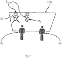
- FIG. 1 an exemplary situation is shown schematically in relation to a user B 1 and a user B 2 .
- the object is achieved by a laminated glass pane with a sensor arrangement according to claim 1.
- the laminated glass pane has a first glass layer and a second glass layer, connected by a combination film, the sensor arrangement being suitable for the approach of a finger to recognize.
- a hologram is arranged at the location of the sensor arrangement, which is optically perceptible to a viewer when illuminated, the hologram being arranged between the first glass layer and the second glass layer.
- the sensor arrangement has a capacitive sensor or an optical sensor.
- a capacitive sensor or an optical sensor.
- the hologram is applied to the combination film.
- the combination film By attaching it to the combination film, production can be simplified and, on the other hand, the hologram can be reliably protected from negative production influences as well as from damage caused by external influences.
- the combination film contains at least one substance selected from the group comprising polybutylene terephthalate (PBT), polycarbonate (PC), polyethylene terephthalate (PET) and polyethylene naphthalate (PEN), Polyvinyl chloride (PVC), polyvinyl fluoride (PVF), polyvinyl butyral (PVB), ethylene vinyl acetate (EVA), polyacrylate (PA), polymethyl methacrylate (PMMA), polyurethane (PUR), and / or mixtures and copolymers thereof.
- PBT polybutylene terephthalate
- PC polycarbonate
- PET polyethylene terephthalate
- PEN polyethylene naphthalate
- PVC Polyvinyl chloride
- PVF polyvinyl fluoride
- PVB polyvinyl butyral
- EVA ethylene vinyl acetate
- PA polyacrylate
- PMMA polymethyl methacrylate
- PUR polyurethane
- At least parts of the sensor arrangement are applied or introduced as wires on or in the combination film.
- the sensor arrangement has a flat, transparent, electrically conductive layer or a plurality of flat, transparent, electrically conductive layers, which are delimited by insulating dividing lines.
- the sensor arrangement and the hologram are arranged on a common section of the combination film or on a carrier within the laminated glass pane. With the joint provision on a common section, the production costs can be reduced.
- the hologram is designed in such a way that a representation of the hologram appears with illumination that is reflective in relation to the viewer.
- the appearance / disappearance of a hologram can be controlled through targeted lighting, so that, for example, only active sensor arrangements can be recognized as such, while inactive sensor arrangements remain hidden.
- different lighting e.g. different angles / different light, to generate the representation of different holograms in relation to the viewer.
- the hologram is designed in such a way that a representation of the hologram appears with illumination that is transmissive with respect to the viewer.
- the appearance / disappearance of a hologram can be controlled by external lighting, so that e.g. only certain sensor arrangements can be recognized as such, while inactive sensor arrangements remain hidden.
- a laminated glass pane arrangement according to the invention has a laminated glass pane and an illumination source which illuminates the hologram in a controllable manner so that it appears to the user.
- the laminated glass pane according to the invention can be used in vehicles or buildings or as an information display. That is, the range of applications is very wide, so that the laminated glass pane according to the invention can be produced inexpensively.
- the laminated glass pane according to the invention can be produced in a simple, cost-effective process that includes obtaining a hologram which includes the introduction of the hologram onto a combination film of the laminated glass pane, the introduction step being selected from lamination or gluing on the combination film, and which has the finishing of the laminated glass pane.
- the hologram is at least partially transparent.
- FIG. 13 is an exemplary situation according to embodiments of the invention schematically in relation to a user B 1 and FIG Figure 3 shown in relation to another person B 2 .
- the laminated glass pane 100 has a sensor arrangement S touch or several sensor arrangements S touch , the laminated glass pane 100 having a first glass layer GS 1 and a second glass layer GS 2 , connected by at least one combination film F or a plurality of combination films F 1 , F 2 .
- the sensor arrangement (s) S touch is / are suitable for detecting the approach of a finger.
- the sensor area itself is identified by the fact that a hologram H is arranged at the location of the sensor arrangement, which is optically perceptible to a viewer B 1 when illuminated, the hologram H being between the first glass layer GS 1 and the second glass layer GS 2 is arranged.
- a sensor arrangement S touch is shown, which is located on the upper edge of a laminated glass pane 100. So that this sensor arrangement S touch can be recognized, a hologram H is provided in relation to the sensor arrangement S touch.
- the hologram H can appear to the user B 1 in a manner similar to the markings M 1 and M 2 .
- the hologram H is designed in such a way that it is partially transparent or even invisible to person B 2 who is not within range of the sensor arrangement S touch and cannot operate the sensor arrangement S touch. That is to say, the hologram H does not restrict the field of view of the person B 2.
- the sensor arrangement S touch can, for example, only be visible to the driver B1, for example to switch certain vehicle elements, while the passenger B2 cannot see the corresponding markings in the form of the hologram H.
- a sensor surface S touch is suitably attached within reach of the passenger B2 - e.g. to control an air conditioning / window / multimedia system - it can be advantageous that it is only visible to the passenger B 2 , while it is partially visible to the driver B 1. remains transparent or even invisible and does not restrict its field of vision.
- hologram H it is possible to provide position-selective markings, e.g. to identify sensor arrangements. This makes use of the fact that a user of a sensor arrangement is located in a certain angular range relative to the laminated glass pane 100, while another observer who is outside the range of the sensor arrangement assumes a different angle relative to the sensor range.
- the laminated glass pane 100 according to the invention is not restricted to a specific sensor technology. Rather, the sensor arrangement S touch can be used together with the most varied of sensor technologies.
- the sensor arrangement has a capacitive sensor or an optical sensor.
- the sensor arrangement (s) S touch is suitable for detecting the approach of a finger.
- the approximation can, for example, in In the case of a capacitive sensor, this can be detected by changing charges on a capacitor.
- detection is possible, for example, on the basis of a shadow cast by means of a light-sensitive resistor or a photoelectric cell, or by means of a camera outside the laminated glass pane 100, which observes the sensor arrangement.
- a shadow cast by means of a light-sensitive resistor or a photoelectric cell
- a camera or by means of a camera outside the laminated glass pane 100, which observes the sensor arrangement.
- not only the approach but also the direct placing of a finger on the sensor area can be recognized.
- the hologram H is on the combination film F; F 1 , F 2 applied.
- FIG. 14 is an exemplary section through a laminated glass pane 100 along the line AA ′ in FIG Figure 2 shown.
- a glass panel 1 and a GS GS glass panel 2 by way of example two combined films F 1 and f 2.
- the hologram at a suitable location can now, for example, on one of the films F 1 or F 2 may be applied, or a carrier T is introduced into a section of the combination film F 1, F 2, or - as shown - between the combination of film F 1, F 2 introduced.
- the cut is in Figure 4 to be understood only as an example and further layers can be provided between the glass pane GS 1 and a glass pane GS 2 .
- the glass pane GS 1 and / or the glass pane GS 2 preferably contain glass, particularly preferably flat glass, float glass, quartz glass, borosilicate glass, soda-lime glass, or clear plastics, preferably rigid clear plastics, in particular polyethylene, polypropylene, polycarbonate , Polymethyl methacrylate, polystyrene, polyamide, polyester, polyvinyl chloride and / or mixtures thereof.
- the glass pane GS 1 and the glass pane GS 2 are transparent, in particular for the use of the laminated glass pane 100 as a windshield or rear window of a vehicle or other uses in which a high light transmission is desired.
- transparent is understood to be a laminated glass pane 100 which has a transmission in the visible spectral range of greater than 70%.
- laminated glass panes 100 that are not relevant to traffic The driver's field of vision, for example for roof windows, but the transmission can also be much smaller, for example greater than 5%.
- the thickness of the glass pane GS 1 and / or the glass pane GS 2 can vary widely and thus be perfectly adapted to the requirements of the individual case. Standard thicknesses from 1.0 mm to 25 mm, preferably from 1.4 mm to 2.5 mm for vehicle glass and preferably from 4 mm to 25 mm for furniture, appliances and buildings, in particular for electric radiators, are preferably used.
- the size of the laminated glass pane 100 can vary widely and depends on the size of the use according to the invention.
- the substrate and, if appropriate, the cover pane have areas of 200 cm 2 to 20 m 2 , which are customary in vehicle construction and the architectural field, for example.
- the laminated glass pane 100 can have any three-dimensional shape.
- the three-dimensional shape preferably has no shadow zone, so that it can be coated, for example, by cathode sputtering.
- the substrates are preferably planar or slightly or strongly curved in one direction or in several directions of space.
- planar glass panes GS 1 and GS 2 are used.
- the glass pane GS 1 and / or GS 2 can be colorless or colored.
- the glass pane GS 1 and / or the glass pane GS 2 preferably have a relative permittivity ⁇ r, 1/4 of 2 to 8 and particularly preferably of 6 to 8. With such relative permittivities, it was possible to achieve a particularly good differentiation between a contact of the contact surface via the outside surface of the substrate and the outside surface of the cover disk.
- the combination film F; F 1 , F 2 at least one substance selected from the group comprising polybutylene terephthalate (PBT), polycarbonate (PC), polyethylene terephthalate (PET) and polyethylene naphthalate (PEN), polyvinyl chloride (PVC), polyvinyl fluoride (PVF), polyvinyl butyral (PVB), ethylene vinyl acetate ( EVA), polypropylene (PP), polyvinyl chloride (PVC), polyacrylate (PA), polymethyl methacrylate (PMMA), polyurethane (PUR), polyacetate resin, casting resins, acrylates, fluorinated ethylene-propylenes, polyvinyl fluoride and / or ethylene-tetrafluoroethylene and / or mixtures and copolymers thereof.
- the combination film F; F 1 , F 2 is transparent.
- the intermediate layer between the first glass pane GS 1 and the second glass pane GS 2 can be made up of one or more combination films F; F 1 , F 2 are formed, the thickness of a combination film F; F 1 , F 2 preferably from Is 0.025mm to 1mm, typically 0.38mm or 0.76mm.
- the intermediate layers are preferably thermoplastic and, after lamination , can glue the glass pane GS 1 , the glass pane GS 2 and any further intermediate layers to one another.
- the intermediate layer preferably has a relative permittivity of 2 to 4 and particularly preferably from 2.1 to 2.9. With such relative permittivities, it was possible to achieve a particularly good differentiation between a contact between the contact surface via the outside surface of the glass pane GS 2 and the outside surface of the glass pane GS 1 .
- the carrier T is preferably a transparent film.
- the carrier T preferably contains or consists of a polyethylene terephthalate (PET) film.
- PET polyethylene terephthalate
- the thickness of the carrier T is preferably from 0.025 mm to 0.1 mm.
- the carrier preferably has a relative permittivity of 2 to 4 and particularly preferably of 2.7 to 3.3.
- parts of the sensor arrangement S touch as wires on or in the combination film F; F 1 , F 2 or on the carrier T are applied or introduced.
- Electrically conductive layers L according to the invention are composed, for example, of DE 20 2008 017 611 U1 , EP 0 847 965 B1 or WO2012 / 052315 A1 known. They typically contain one or more, for example two, three or four, electrically conductive, functional layers.
- the functional layers preferably contain at least one metal, for example silver, gold, copper, nickel and / or chromium, or a metal alloy.
- the functional layers particularly preferably contain at least 90% by weight of the metal, in particular at least 99.9% by weight of the metal.
- the functional layers can be made from consist of the metal or metal alloy.
- the functional layers particularly preferably contain silver or an alloy containing silver. Such functional layers have a particularly advantageous electrical conductivity with simultaneous high transmission in the visible spectral range.
- the thickness of a functional layer is preferably from 5 nm to 50 nm, particularly preferably from 8 nm to 25 nm. In this range for the thickness of the functional layer, an advantageously high transmission in the visible spectral range and a particularly advantageous electrical conductivity are achieved.
- At least one dielectric layer is typically arranged between two adjacent functional layers.
- a further dielectric layer is preferably arranged below the first and / or above the last functional layer.
- a dielectric layer contains at least one single layer made of a dielectric material, for example containing a nitride such as silicon nitride or an oxide such as aluminum oxide.
- the dielectric layer can also comprise a plurality of individual layers, for example individual layers made of a dielectric material, smoothing layers, adaptation layers, blocker layers and / or antireflection layers.
- the thickness of a dielectric layer is, for example, from 10 nm to 200 nm.
- This layer structure is generally obtained through a sequence of deposition processes, which is carried out using a vacuum process such as magnetic field-assisted cathode sputtering.
- Such electrically conductive layers L preferably contain indium tin oxide (ITO), fluorine-doped tin oxide (SnO 2 : F) or aluminum-doped zinc oxide (ZnO: Al).
- ITO indium tin oxide
- SnO 2 : F fluorine-doped tin oxide
- ZnO aluminum-doped zinc oxide
- the electrically conductive layer L can in principle be any coating that can be electrically contacted. If the laminated glass pane 100 according to the invention is intended to enable transparency, as is the case, for example, with panes in the window area, the electrically conductive layer L is preferably transparent. In an advantageous embodiment, the electrically conductive layer L is a layer or a layer structure of several individual layers with a total thickness of less than or equal to 2 ⁇ m, particularly preferably less than or equal to 1 ⁇ m.
- the structure and coordination of sensor electronics is coordinated such that when the outside pane surface IV of the glass pane GS 1 is touched, a switching signal is triggered above the contact area 11 of the capacitive switching area outside pane surface I of the glass pane GS 2 above the capacitive switching range no switching signal is triggered.
- the thicknesses and the materials of the composite pane 100 according to the invention are selected according to the invention in such a way that the area capacitance layer c I between the contact area 11 and the outside surface IV of the glass pane GS 1 is greater than the area capacity layer c A between the contact area 11 and the outside surface I. the glass pane GS 2 is.
- the laminated glass pane can also have a low-E coating on the inside surface IV of the laminated glass pane 100, at least one capacitive switching area being electrically separated from the low-E coating by at least one coating-free dividing line U.
- the outer surface of the laminated glass pane 100 here means the surface of the pane that faces outwards, that is to say away from the (vehicle) interior.
- Inner surface accordingly means the surface of the laminated glass pane 100 which faces the (vehicle) interior.
- This low-E coating contains at least one functional layer and optionally one or more adhesive layers, barrier layers and / or anti-reflective layers.
- the low-E coating is preferably a layer system of at least one in each case Adhesive layer, a functional layer, a barrier layer, an anti-reflective layer and a further barrier layer.
- Particularly suitable low-E coatings contain a functional layer of at least one electrically conductive oxide (TCO), preferably indium tin oxide (ITO ), fluorine-doped tin oxide (SnO 2 : F), antimony-doped tin oxide (SnO 2 : Sb), aluminum-doped Zinc oxide (ZnO: AI) and / or gallium-doped zinc oxide (ZnO: Ga).
- TCO electrically conductive oxide
- ITO indium tin oxide
- F fluorine-doped tin oxide
- SnO 2 : F fluorine-doped tin oxide
- SnO 2 antimony-doped tin oxide
- ZnO aluminum-doped Zinc oxide
- ZnO: Ga gallium-doped zinc oxide
- Particularly advantageous low-E coatings have an interior emissivity of the laminated glass pane 100 according to the invention of less than or equal to 60%, preferably less than or equal to 45%, particularly preferably less than or equal to 30% and in particular less than or equal to 20%.
- Emissivity on the inside is the measure that indicates how much heat radiation the pane emits in the installed position compared to an ideal heat radiator (a black body) in an interior, for example a building or a vehicle.
- Emissivity is understood to mean the normal total emissivity at 283 K according to the EN 12898 standard.
- the sheet resistance of such an exemplary Low-E coating is from 10 ohms / square to 200 ohms / square and preferably from 10 ohms / square to 100 ohms / square, particularly preferably from 15 ohms / square to 50 ohms / square and especially from 20 ohms / square to 35 ohms / square.
- the absorption of the Low-E coating in the visible spectral range is preferably from about 1% to about 15%, particularly preferably from about 1% to about 7%.
- the absorption of the coating can be determined by measuring the absorption of a coated pane and subtracting the absorption of the uncoated pane.
- the pane preferably has a color value a * from -15 to +5 and a color value b * from -15 to +5, viewed from the side provided with the low-E coating according to the invention.
- the details a * and b * relate to the color coordinates according to the colorimetric model (L * a * b * color space).
- An advantageous low-E coating has a low absorption and a low reflection and therefore a high transmission in the visible spectral range.
- the Low-E coating can therefore also be used on windows where a significant reduction in transmission is not desired, for example window panes in buildings, or is prohibited by law, for example windshields or front side windows in motor vehicles.
- Another advantageous transparent electrically conductive layer L can also have a sheet resistance of 0.4 ohm / square to 200 ohm / square.
- the electrically conductive layer according to the invention has a sheet resistance of 0.5 ohm / square to 20 ohm / square.
- Coatings with such surface resistances are suitable, among other things, for heating vehicle windows with typical on-board voltages of 12 V to 48 volts or in electric vehicles with typical on-board voltages of up to 500 V.
- the sensor arrangement S touch has at least one flat, transparent, electrically conductive layer L which is delimited by insulating dividing lines U.
- a corresponding capacitive sensor is formed there on a carrier T which has an electrically conductive coating L.
- This has two comparatively large areas A 1 and A 2 , which are arranged at the upper end shown.
- the surfaces are connected to exemplary connections AN 1 and AN 2 via connections V 1 and V 2 .
- the connections AN 1 and AN 1 are connected to exemplary sensor evaluation electronics via two flat ribbon connections K 1 and K 2 attached by means of solder LOT.
- Other forms of sensor construction, in particular wireless connected sensors, are hereby explicitly not excluded.
- the plate A 2 and the connections V 2 and the connection A 2 are formed from the electrically conductive layer L by means of the dividing line U.
- the plate A 1 and the connections V 1 and the connection A 1 are formed from the electrically conductive layer L by means of a further dividing line U.
- These dividing line (s) U can be structured, for example, by means of a laser (ablation).
- a holographic structure (structure having different thickness profiles and / or refractive index profiles) is produced by (hot) embossing a, for example, embossable lacquer on an exemplary PET film, for example 19 ⁇ m-50 ⁇ m thick.
- this PET film can also serve as a carrier T for electrical layers L of the sensor arrangement S touch .
- such a PET film has a tensile strength of approximately 24 kgf / mm 2 , the elongation at break being 120% - 150% and the heat shrinkage at 150 ° / 30min being 1% and less.
- such PET films have a haze of 1% with a transmission of 90%.
- Such a carrier T can, for example, be coated with a highly reflective metallization M, it also being possible for further layers to be provided for application.
- the metallization M can e.g. be produced on the basis of ZnS, which has a refractive index of 2.3 - 2.4 with a 35% reflectivity.
- a coating C 1 can be located on the side facing away from the viewer, as required. This coating C 1 can, for example, allow printing with non-holographic elements.
- a separating layer RC can be located on the side facing the viewer as required. Furthermore, a second coating C 2 can optionally be provided, which, for example, carries the embossable lacquer PL.
- the hologram H is designed in such a way that it is illuminated by ambient light and also by targeted lighting, be it by means of an illumination that is integrated into the pane / sensor arrangement Illumination by means of suitable (organic) light-emitting diodes (p) LEDs, be it by an illumination source arranged outside the laminated glass pane 100, is illuminated in such a way that the user of the sensor arrangement S touch can localize the sensor arrangement.
- suitable (organic) light-emitting diodes (p) LEDs be it by an illumination source arranged outside the laminated glass pane 100, is illuminated in such a way that the user of the sensor arrangement S touch can localize the sensor arrangement.
- the hologram H can be designed, for example, in such a way that a representation of the hologram H appears with illumination that is reflective in relation to the viewer.
- a hologram can be controlled through targeted lighting so that, for example, only active sensor arrangements can be recognized as such, while inactive sensor arrangements remain hidden.
- different illuminations e.g. different angles / different light in relation to the laminated glass pane 100 or an embossing of the hologram H, to produce the representation of different holograms in relation to the viewer.
- a representation of the hologram H appears in the case of illumination that is transmissive with respect to the viewer.
- the hologram H can also have several superimposed representations which, depending on the lighting (e.g. the angle of the lighting), are displayed in relation to the user.
- One embodiment of the invention shows a laminated glass pane arrangement which has a laminated glass pane 100 and an illumination source, the illumination source controllably illuminating the hologram H so that it appears to the user.
- the illumination source preferably has an LED or OLED.
- the particular advantage lies in the small dimensions and the low power consumption.
- the wavelength range emitted by the illumination source can be freely selected in the range of visible light, for example according to practical and / or aesthetic aspects.
- the light irradiation means can comprise optical elements, in particular for directing the light, preferably a reflector and / or an optical waveguide, for example a glass fiber or a polymer optical fiber.
- the illumination source can be at any point (relative to) the glass pane GS 1 or the glass pane GS 2 be arranged, in particular on the side edge of the glass pane GS 1 or the glass pane GS 2 or in a small recess in the middle of the glass pane GS 1 or the glass pane GS 2 .
- the light deflecting means preferably has particles, point grids, stickers, deposits, notches, incisions, line grids, prints and / or screen prints and is suitable for decoupling the light transported in the glass pane GS 1 or the glass pane GS 2 from the same.
- the light deflection means can be arranged at any desired position on the plane of the glass pane GS 1 or the glass pane GS 2 . It is particularly advantageous if the light deflection means is arranged in the area or in the immediate vicinity of the contact area and thus enables the otherwise barely visible contact area of the sensor arrangement S touch to be found quickly. This is particularly advantageous at night or in the dark.
- light can be guided to the contact area of the sensor arrangement S touch through a light guide arranged on the glass pane GS 1 or the glass pane GS 2 , or an intermediate layer (e.g. the combination film F, F 1 , F 2) and mark it.
- a light guide arranged on the glass pane GS 1 or the glass pane GS 2 , or an intermediate layer (e.g. the combination film F, F 1 , F 2) and mark it.
- the light irradiation means together with the light deflection means can visualize information on the pane, for example reproduce the switching state of the capacitive switching area or indicate whether, for example, an electrical function is switched on or off.
- the laminated glass pane 100 according to the invention can be used in vehicles or buildings or as an information display.
- the range of applications is very wide, so that the laminated glass panes 100 according to the invention can be produced inexpensively.
- a hologram H is first obtained.
- This hologram H can be part of the sensor arrangement S touch or it can be an independent hologram H (for example on a carrier T).
- the hologram H obtained is introduced into a preliminary product of the laminated glass pane 100, the introduction step being selected from lamination, gluing, Hang up. After the introduction and any further intermediate steps with regard to the sensor arrangement, the laminated glass pane 100 is completed.
- the sensor arrangement S touch is represented in a position-sensitive manner.
- the invention makes it its own that a user B 1 is at a typical distance (approximately 60 cm) in front of the laminated glass pane 100 so that he is able to operate the sensor of the sensor arrangement S touch.
- the hologram H is designed in such a way that, given the appropriate incidence of light, it can be seen well essentially at this distance and when viewed from a certain angular range, while it becomes partially transparent or even completely invisible for "viewers" from other distances and / or angular ranges.
- the ambient light is generally sufficient during the day to make a hologram H visible to the viewer B 1 , it may be necessary to provide external lighting in the dark so that the hologram H is visible again.
- This source of illumination can in turn be suitably placed. For example, this can be arranged in a vehicle on the roof lining, the dashboard or an A-pillar, in a rear-view mirror holder, etc., so that the light from the illumination source does not disturb the viewer B 1.
- holograms H Another advantage of holograms H is that these holograms cannot be seen on the side facing away from the user.
- a sensor arrangement S touch and the hologram H are arranged for this purpose in such a way that they can be seen on the inside of a vehicle.
- the hologram H cannot be seen on the outside. The localization of the sensor arrangement S touch cannot therefore be found, or cannot be found easily, so that incorrect operation from the outside is made more difficult.
Landscapes
- Engineering & Computer Science (AREA)
- Theoretical Computer Science (AREA)
- Physics & Mathematics (AREA)
- General Physics & Mathematics (AREA)
- General Engineering & Computer Science (AREA)
- Human Computer Interaction (AREA)
- Civil Engineering (AREA)
- Structural Engineering (AREA)
- Accounting & Taxation (AREA)
- Marketing (AREA)
- Business, Economics & Management (AREA)
- Mechanical Engineering (AREA)
- Joining Of Glass To Other Materials (AREA)
- Laminated Bodies (AREA)
- Holo Graphy (AREA)
Priority Applications (1)
| Application Number | Priority Date | Filing Date | Title |
|---|---|---|---|
| PL17711212T PL3465396T3 (pl) | 2016-05-23 | 2017-03-20 | Szyba laminowana z układem czujnikowym i sposób wytwarzania szyby laminowanej z układem czujnikowym |
Applications Claiming Priority (2)
| Application Number | Priority Date | Filing Date | Title |
|---|---|---|---|
| EP16170773 | 2016-05-23 | ||
| PCT/EP2017/056478 WO2017202517A1 (de) | 2016-05-23 | 2017-03-20 | Verbundglas-scheibe mit einer sensoranordnung und verfahren zur herstellung einer verbundglas-scheibe mit einer sensoranordnung |
Publications (2)
| Publication Number | Publication Date |
|---|---|
| EP3465396A1 EP3465396A1 (de) | 2019-04-10 |
| EP3465396B1 true EP3465396B1 (de) | 2021-10-27 |
Family
ID=56203101
Family Applications (1)
| Application Number | Title | Priority Date | Filing Date |
|---|---|---|---|
| EP17711212.5A Active EP3465396B1 (de) | 2016-05-23 | 2017-03-20 | Verbundglas-scheibe mit einer sensoranordnung und verfahren zur herstellung einer verbundglas-scheibe mit einer sensoranordnung |
Country Status (12)
| Country | Link |
|---|---|
| US (1) | US20190018366A1 (pl) |
| EP (1) | EP3465396B1 (pl) |
| JP (1) | JP6791980B2 (pl) |
| KR (1) | KR20180100061A (pl) |
| CN (1) | CN108027690B (pl) |
| BR (1) | BR112018013787A2 (pl) |
| CA (1) | CA3015171A1 (pl) |
| ES (1) | ES2901893T3 (pl) |
| HU (1) | HUE057645T2 (pl) |
| MA (1) | MA45082B1 (pl) |
| PL (1) | PL3465396T3 (pl) |
| WO (1) | WO2017202517A1 (pl) |
Families Citing this family (7)
| Publication number | Priority date | Publication date | Assignee | Title |
|---|---|---|---|---|
| CA3002307A1 (en) * | 2015-11-06 | 2017-05-11 | Saint-Gobain Glass France | Pane arrangement having a heatable composite pane having a capacitive switching region |
| US10694587B2 (en) * | 2015-11-06 | 2020-06-23 | Saint-Gobain Glass France | Electrically heatable composite pane having a capacitive switching region |
| CO2018006043A1 (es) * | 2018-03-30 | 2018-08-31 | Agp America Sa | Laminado automotriz con cámara embebida |
| DE102018007108A1 (de) * | 2018-09-07 | 2020-03-12 | Giesecke+Devrient Currency Technology Gmbh | Verbundglas mit betrachtungswinkelabhängig farbvariabler Zwischenfolie |
| EP3943291A4 (en) * | 2019-03-20 | 2022-12-14 | Sekisui Chemical Co., Ltd. | INTERMEDIATE FILM FOR LAMINATED GLASS, AND LAMINATED GLASS |
| US20210252835A1 (en) * | 2020-02-18 | 2021-08-19 | GM Global Technology Operations LLC | Vehicle glass with integrated sensor chip |
| CN113692350B (zh) * | 2020-03-13 | 2023-08-25 | 法国圣戈班玻璃厂 | 具有光聚合物层和pdlc元件的复合玻璃板 |
Family Cites Families (32)
| Publication number | Priority date | Publication date | Assignee | Title |
|---|---|---|---|---|
| DE3532120A1 (de) | 1985-09-10 | 1987-03-19 | Ver Glaswerke Gmbh | Windschutzscheibe mit einer reflektierenden einrichtung zur einspiegelung von optischen signalen in das gesichtsfeld des fahrers |
| JPH06336126A (ja) * | 1993-05-27 | 1994-12-06 | Isuzu Motors Ltd | 車両用表示装置 |
| KR960016721B1 (ko) * | 1993-12-23 | 1996-12-20 | 현대전자산업 주식회사 | 홀로그램 광학 소자를 이용한 자동차용 헤드 엎 디스플레이장치 |
| JPH08169257A (ja) * | 1994-12-19 | 1996-07-02 | Asahi Glass Co Ltd | ヘッドアップディスプレイシステム |
| DE19512864C1 (de) * | 1995-04-06 | 1996-08-22 | Sekurit Saint Gobain Deutsch | Autoglasscheibe für einen Regensensor |
| JP4417440B2 (ja) * | 1996-02-16 | 2010-02-17 | 大日本印刷株式会社 | 拡散ホログラムタッチパネル |
| FR2757151B1 (fr) | 1996-12-12 | 1999-01-08 | Saint Gobain Vitrage | Vitrage comprenant un substrat muni d'un empilement de couches minces pour la protection solaire et/ou l'isolation thermique |
| DE19727220C2 (de) | 1997-06-26 | 1999-08-26 | Captron Elect Gmbh | Schaltungsanordnung für einen kapazitiven Schalter |
| JPH11161215A (ja) * | 1997-11-28 | 1999-06-18 | Asahi Glass Co Ltd | 光装飾フィルム付き車両用窓ガラス |
| US6452514B1 (en) | 1999-01-26 | 2002-09-17 | Harald Philipp | Capacitive sensor and array |
| JP2002040560A (ja) * | 2000-07-31 | 2002-02-06 | Denso Corp | ホログラムディスプレイ装置 |
| JP2003005617A (ja) * | 2001-02-23 | 2003-01-08 | Denso Corp | ホログラムディスプレイ装置及びテレビ電話 |
| US6654070B1 (en) | 2001-03-23 | 2003-11-25 | Michael Edward Rofe | Interactive heads up display (IHUD) |
| DE10155273B4 (de) * | 2001-11-09 | 2006-03-23 | Guardian Flachglas Gmbh | Verwendung einer Verglasungseinheit als Brandschutzglas |
| BE1015302A3 (fr) | 2003-01-10 | 2005-01-11 | Glaverbel | Vitrage comportant des composants electroniques. |
| FR2859525B1 (fr) | 2003-09-09 | 2006-06-02 | Delphi Tech Inc | Commutateur capacitif glissant |
| DE202006006192U1 (de) | 2006-04-18 | 2006-07-27 | Captron Electronic Gmbh | Türbetätigungstaster |
| US7936489B2 (en) * | 2007-02-09 | 2011-05-03 | GM Global Technology Operations LLC | Holographic information display |
| GB0705120D0 (en) * | 2007-03-16 | 2007-04-25 | Pilkington Group Ltd | Vehicle glazing |
| DE202008017611U1 (de) | 2008-12-20 | 2010-04-22 | Saint-Gobain Sekurit Deutschland Gmbh & Co. Kg | Scheibenförmiges, transparentes, elektrisch beheizbares Verbundmaterial |
| EP2409833A1 (de) * | 2010-07-23 | 2012-01-25 | Saint-Gobain Glass France | Verbundglasscheibe als Head-Up-Display |
| JP5950233B2 (ja) * | 2010-10-01 | 2016-07-13 | パナソニックIpマネジメント株式会社 | シースルーディスプレイ装置及びシースルーディスプレイ装置を搭載した車両 |
| EP2444381A1 (de) | 2010-10-19 | 2012-04-25 | Saint-Gobain Glass France | Transparente Scheibe |
| PL2766774T3 (pl) | 2011-10-10 | 2019-07-31 | Saint-Gobain Glass France | Elektrochromowe oszklenie zespolone z pojemnościowym przyciskiem czujnikowym |
| EP2795720B1 (de) * | 2011-12-20 | 2020-08-26 | Saint-Gobain Glass France | Verbundscheibe mit antennenstruktur und integrierter schaltfläche |
| FR2985042B1 (fr) * | 2011-12-22 | 2014-01-17 | Saint Gobain | Dispositif de visualisation d'une image sur un support feuillete |
| WO2013131698A1 (de) * | 2012-03-05 | 2013-09-12 | Saint-Gobain Glass France | Verfahren zur herstellung einer verbundglasscheibe mit sensorfenster |
| JP2013186737A (ja) * | 2012-03-08 | 2013-09-19 | Stanley Electric Co Ltd | タッチパネル式操作装置 |
| CN203063693U (zh) * | 2012-12-19 | 2013-07-17 | 浙江吉利汽车研究院有限公司杭州分公司 | 一种汽车全息组合仪表装置 |
| EA034788B1 (ru) * | 2014-04-24 | 2020-03-20 | Сэн-Гобэн Гласс Франс | Панель с подсвечиваемой поверхностью переключения и функцией нагрева |
| HUE050460T2 (hu) * | 2014-04-24 | 2020-12-28 | Saint Gobain | Villamosan fûthetõ tábla kapcsolási tartománnyal |
| EA034011B1 (ru) * | 2015-01-20 | 2019-12-18 | Сэн-Гобэн Гласс Франс | Многослойное стекло с емкостной зоной коммутации |
-
2017
- 2017-03-20 MA MA45082A patent/MA45082B1/fr unknown
- 2017-03-20 WO PCT/EP2017/056478 patent/WO2017202517A1/de active Application Filing
- 2017-03-20 CA CA3015171A patent/CA3015171A1/en not_active Abandoned
- 2017-03-20 JP JP2018550745A patent/JP6791980B2/ja active Active
- 2017-03-20 HU HUE17711212A patent/HUE057645T2/hu unknown
- 2017-03-20 PL PL17711212T patent/PL3465396T3/pl unknown
- 2017-03-20 US US16/070,258 patent/US20190018366A1/en not_active Abandoned
- 2017-03-20 ES ES17711212T patent/ES2901893T3/es active Active
- 2017-03-20 EP EP17711212.5A patent/EP3465396B1/de active Active
- 2017-03-20 BR BR112018013787A patent/BR112018013787A2/pt not_active IP Right Cessation
- 2017-03-20 CN CN201780000406.1A patent/CN108027690B/zh active Active
- 2017-03-20 KR KR1020187021802A patent/KR20180100061A/ko not_active Application Discontinuation
Non-Patent Citations (1)
| Title |
|---|
| None * |
Also Published As
| Publication number | Publication date |
|---|---|
| CA3015171A1 (en) | 2017-11-30 |
| MA45082A (fr) | 2021-04-28 |
| PL3465396T3 (pl) | 2022-01-31 |
| HUE057645T2 (hu) | 2022-05-28 |
| CN108027690B (zh) | 2022-03-25 |
| JP2019512747A (ja) | 2019-05-16 |
| ES2901893T3 (es) | 2022-03-24 |
| KR20180100061A (ko) | 2018-09-06 |
| CN108027690A (zh) | 2018-05-11 |
| EP3465396A1 (de) | 2019-04-10 |
| US20190018366A1 (en) | 2019-01-17 |
| WO2017202517A1 (de) | 2017-11-30 |
| MA45082B1 (fr) | 2021-12-31 |
| JP6791980B2 (ja) | 2020-11-25 |
| BR112018013787A2 (pt) | 2018-12-11 |
Similar Documents
| Publication | Publication Date | Title |
|---|---|---|
| EP3465396B1 (de) | Verbundglas-scheibe mit einer sensoranordnung und verfahren zur herstellung einer verbundglas-scheibe mit einer sensoranordnung | |
| EP3247558B1 (de) | Verbundscheibe mit kapazitivem schaltbereich | |
| EP3372052B1 (de) | Scheibenanordnung mit beheizbarer verbundscheibe mit kapazitivem schaltbereich | |
| EP3386748B1 (de) | Fahrzeug-verbundscheibe mit integriertem lichtsensor | |
| EP3535847B1 (de) | Scheibenanordnung mit einer verbundscheibe mit erweitertem kapazitivem schaltbereich | |
| EP3338367B1 (de) | Scheibenanordnung mit scheibe mit low-e-beschichtung und kapazitivem schaltbereich | |
| EP3135075A1 (de) | Elektrisch beheizbare scheibe mit schaltbereich | |
| EP3487720B1 (de) | Fensterscheibe mit kapazitivem schaltbereich zur berührungslosen steuerung einer funktion | |
| EP3372051A1 (de) | Elektrisch beheizbare verbundscheibe mit kapazitivem schaltbereich | |
| CN110546022B (zh) | 通过深色内部堆叠体和外部堆叠体的组合而具有改进的视觉印象的pdlc车辆玻璃板 | |
| EP4021722B1 (de) | Verbundscheibe mit integrierter sonnenblende und verfahren zu deren herstellung | |
| DE202021004291U1 (de) | Verglasung mit Lichtquelle | |
| EP3784490A1 (de) | Verbundscheibe mit elektrisch schaltbarem funktionselement in thermoplastischer zwischenschicht | |
| EP3606780A1 (de) | Intelligentes durchblicksteuerungssystem | |
| WO2021156143A1 (de) | Verbundscheibenanordnung mit touch-bedienelement zur steuerung einer funktion | |
| WO2022223409A1 (de) | Verfahren zur steuerung einer verglasungseinheit mit elektrisch steuerbaren optischen eigenschaften | |
| WO2024002696A1 (de) | Anordnung für ein fahrerassistenzsystem | |
| EP4320475A1 (de) | Beheizbare verbundscheibe für eine projektionsanordnung | |
| WO2022157035A1 (de) | Verbundscheibe mit elektrisch steuerbaren optischen eigenschaften und steuereinheit | |
| WO2024056340A1 (de) | Verbundscheibe mit bereichsweise aufgebrachter beheizbarer reflexionsschicht | |
| DE202022106921U1 (de) | Verglasungselement mit einer lichtleitenden transparenten Schicht | |
| WO2024068306A1 (de) | Verbundscheibe mit bereichsweise aufgebrachter reflexionsschicht | |
| EP3927542A1 (de) | Verbundscheibe mit integriertem lichtsensor |
Legal Events
| Date | Code | Title | Description |
|---|---|---|---|
| STAA | Information on the status of an ep patent application or granted ep patent |
Free format text: STATUS: UNKNOWN |
|
| STAA | Information on the status of an ep patent application or granted ep patent |
Free format text: STATUS: THE INTERNATIONAL PUBLICATION HAS BEEN MADE |
|
| PUAI | Public reference made under article 153(3) epc to a published international application that has entered the european phase |
Free format text: ORIGINAL CODE: 0009012 |
|
| STAA | Information on the status of an ep patent application or granted ep patent |
Free format text: STATUS: REQUEST FOR EXAMINATION WAS MADE |
|
| 17P | Request for examination filed |
Effective date: 20181112 |
|
| AK | Designated contracting states |
Kind code of ref document: A1 Designated state(s): AL AT BE BG CH CY CZ DE DK EE ES FI FR GB GR HR HU IE IS IT LI LT LU LV MC MK MT NL NO PL PT RO RS SE SI SK SM TR |
|
| AX | Request for extension of the european patent |
Extension state: BA ME |
|
| DAX | Request for extension of the european patent (deleted) | ||
| RAV | Requested validation state of the european patent: fee paid |
Extension state: MA Effective date: 20181112 |
|
| RAP1 | Party data changed (applicant data changed or rights of an application transferred) |
Owner name: SAINT-GOBAIN GLASS FRANCE |
|
| GRAP | Despatch of communication of intention to grant a patent |
Free format text: ORIGINAL CODE: EPIDOSNIGR1 |
|
| STAA | Information on the status of an ep patent application or granted ep patent |
Free format text: STATUS: GRANT OF PATENT IS INTENDED |
|
| INTG | Intention to grant announced |
Effective date: 20201111 |
|
| GRAJ | Information related to disapproval of communication of intention to grant by the applicant or resumption of examination proceedings by the epo deleted |
Free format text: ORIGINAL CODE: EPIDOSDIGR1 |
|
| STAA | Information on the status of an ep patent application or granted ep patent |
Free format text: STATUS: REQUEST FOR EXAMINATION WAS MADE |
|
| INTC | Intention to grant announced (deleted) | ||
| GRAJ | Information related to disapproval of communication of intention to grant by the applicant or resumption of examination proceedings by the epo deleted |
Free format text: ORIGINAL CODE: EPIDOSDIGR1 |
|
| GRAP | Despatch of communication of intention to grant a patent |
Free format text: ORIGINAL CODE: EPIDOSNIGR1 |
|
| GRAP | Despatch of communication of intention to grant a patent |
Free format text: ORIGINAL CODE: EPIDOSNIGR1 |
|
| STAA | Information on the status of an ep patent application or granted ep patent |
Free format text: STATUS: GRANT OF PATENT IS INTENDED |
|
| INTG | Intention to grant announced |
Effective date: 20210528 |
|
| INTG | Intention to grant announced |
Effective date: 20210607 |
|
| GRAS | Grant fee paid |
Free format text: ORIGINAL CODE: EPIDOSNIGR3 |
|
| GRAA | (expected) grant |
Free format text: ORIGINAL CODE: 0009210 |
|
| STAA | Information on the status of an ep patent application or granted ep patent |
Free format text: STATUS: THE PATENT HAS BEEN GRANTED |
|
| AK | Designated contracting states |
Kind code of ref document: B1 Designated state(s): AL AT BE BG CH CY CZ DE DK EE ES FI FR GB GR HR HU IE IS IT LI LT LU LV MC MK MT NL NO PL PT RO RS SE SI SK SM TR |
|
| REG | Reference to a national code |
Ref country code: GB Ref legal event code: FG4D Free format text: NOT ENGLISH |
|
| REG | Reference to a national code |
Ref country code: CH Ref legal event code: EP |
|
| REG | Reference to a national code |
Ref country code: AT Ref legal event code: REF Ref document number: 1442370 Country of ref document: AT Kind code of ref document: T Effective date: 20211115 |
|
| REG | Reference to a national code |
Ref country code: DE Ref legal event code: R096 Ref document number: 502017011825 Country of ref document: DE |
|
| REG | Reference to a national code |
Ref country code: IE Ref legal event code: FG4D Free format text: LANGUAGE OF EP DOCUMENT: GERMAN |
|
| REG | Reference to a national code |
Ref country code: MA Ref legal event code: VAGR Ref document number: 45082 Country of ref document: MA Kind code of ref document: B1 |
|
| REG | Reference to a national code |
Ref country code: NL Ref legal event code: FP |
|
| REG | Reference to a national code |
Ref country code: LT Ref legal event code: MG9D |
|
| REG | Reference to a national code |
Ref country code: SK Ref legal event code: T3 Ref document number: E 38966 Country of ref document: SK |
|
| REG | Reference to a national code |
Ref country code: ES Ref legal event code: FG2A Ref document number: 2901893 Country of ref document: ES Kind code of ref document: T3 Effective date: 20220324 |
|
| PG25 | Lapsed in a contracting state [announced via postgrant information from national office to epo] |
Ref country code: RS Free format text: LAPSE BECAUSE OF FAILURE TO SUBMIT A TRANSLATION OF THE DESCRIPTION OR TO PAY THE FEE WITHIN THE PRESCRIBED TIME-LIMIT Effective date: 20211027 Ref country code: LT Free format text: LAPSE BECAUSE OF FAILURE TO SUBMIT A TRANSLATION OF THE DESCRIPTION OR TO PAY THE FEE WITHIN THE PRESCRIBED TIME-LIMIT Effective date: 20211027 Ref country code: FI Free format text: LAPSE BECAUSE OF FAILURE TO SUBMIT A TRANSLATION OF THE DESCRIPTION OR TO PAY THE FEE WITHIN THE PRESCRIBED TIME-LIMIT Effective date: 20211027 Ref country code: BG Free format text: LAPSE BECAUSE OF FAILURE TO SUBMIT A TRANSLATION OF THE DESCRIPTION OR TO PAY THE FEE WITHIN THE PRESCRIBED TIME-LIMIT Effective date: 20220127 |
|
| PGFP | Annual fee paid to national office [announced via postgrant information from national office to epo] |
Ref country code: HU Payment date: 20220212 Year of fee payment: 6 |
|
| REG | Reference to a national code |
Ref country code: HU Ref legal event code: AG4A Ref document number: E057645 Country of ref document: HU |
|
| PG25 | Lapsed in a contracting state [announced via postgrant information from national office to epo] |
Ref country code: IS Free format text: LAPSE BECAUSE OF FAILURE TO SUBMIT A TRANSLATION OF THE DESCRIPTION OR TO PAY THE FEE WITHIN THE PRESCRIBED TIME-LIMIT Effective date: 20220227 Ref country code: SE Free format text: LAPSE BECAUSE OF FAILURE TO SUBMIT A TRANSLATION OF THE DESCRIPTION OR TO PAY THE FEE WITHIN THE PRESCRIBED TIME-LIMIT Effective date: 20211027 Ref country code: PT Free format text: LAPSE BECAUSE OF FAILURE TO SUBMIT A TRANSLATION OF THE DESCRIPTION OR TO PAY THE FEE WITHIN THE PRESCRIBED TIME-LIMIT Effective date: 20220228 Ref country code: NO Free format text: LAPSE BECAUSE OF FAILURE TO SUBMIT A TRANSLATION OF THE DESCRIPTION OR TO PAY THE FEE WITHIN THE PRESCRIBED TIME-LIMIT Effective date: 20220127 Ref country code: LV Free format text: LAPSE BECAUSE OF FAILURE TO SUBMIT A TRANSLATION OF THE DESCRIPTION OR TO PAY THE FEE WITHIN THE PRESCRIBED TIME-LIMIT Effective date: 20211027 Ref country code: HR Free format text: LAPSE BECAUSE OF FAILURE TO SUBMIT A TRANSLATION OF THE DESCRIPTION OR TO PAY THE FEE WITHIN THE PRESCRIBED TIME-LIMIT Effective date: 20211027 Ref country code: GR Free format text: LAPSE BECAUSE OF FAILURE TO SUBMIT A TRANSLATION OF THE DESCRIPTION OR TO PAY THE FEE WITHIN THE PRESCRIBED TIME-LIMIT Effective date: 20220128 |
|
| PGFP | Annual fee paid to national office [announced via postgrant information from national office to epo] |
Ref country code: TR Payment date: 20220316 Year of fee payment: 6 Ref country code: SK Payment date: 20220215 Year of fee payment: 6 Ref country code: RO Payment date: 20220301 Year of fee payment: 6 Ref country code: PL Payment date: 20220214 Year of fee payment: 6 Ref country code: NL Payment date: 20220215 Year of fee payment: 6 Ref country code: LU Payment date: 20220314 Year of fee payment: 6 Ref country code: IT Payment date: 20220210 Year of fee payment: 6 Ref country code: CZ Payment date: 20220228 Year of fee payment: 6 Ref country code: BE Payment date: 20220221 Year of fee payment: 6 |
|
| REG | Reference to a national code |
Ref country code: DE Ref legal event code: R097 Ref document number: 502017011825 Country of ref document: DE |
|
| PG25 | Lapsed in a contracting state [announced via postgrant information from national office to epo] |
Ref country code: SM Free format text: LAPSE BECAUSE OF FAILURE TO SUBMIT A TRANSLATION OF THE DESCRIPTION OR TO PAY THE FEE WITHIN THE PRESCRIBED TIME-LIMIT Effective date: 20211027 Ref country code: EE Free format text: LAPSE BECAUSE OF FAILURE TO SUBMIT A TRANSLATION OF THE DESCRIPTION OR TO PAY THE FEE WITHIN THE PRESCRIBED TIME-LIMIT Effective date: 20211027 Ref country code: DK Free format text: LAPSE BECAUSE OF FAILURE TO SUBMIT A TRANSLATION OF THE DESCRIPTION OR TO PAY THE FEE WITHIN THE PRESCRIBED TIME-LIMIT Effective date: 20211027 |
|
| PGFP | Annual fee paid to national office [announced via postgrant information from national office to epo] |
Ref country code: ES Payment date: 20220406 Year of fee payment: 6 |
|
| PLBE | No opposition filed within time limit |
Free format text: ORIGINAL CODE: 0009261 |
|
| STAA | Information on the status of an ep patent application or granted ep patent |
Free format text: STATUS: NO OPPOSITION FILED WITHIN TIME LIMIT |
|
| 26N | No opposition filed |
Effective date: 20220728 |
|
| PG25 | Lapsed in a contracting state [announced via postgrant information from national office to epo] |
Ref country code: MC Free format text: LAPSE BECAUSE OF FAILURE TO SUBMIT A TRANSLATION OF THE DESCRIPTION OR TO PAY THE FEE WITHIN THE PRESCRIBED TIME-LIMIT Effective date: 20211027 Ref country code: AL Free format text: LAPSE BECAUSE OF FAILURE TO SUBMIT A TRANSLATION OF THE DESCRIPTION OR TO PAY THE FEE WITHIN THE PRESCRIBED TIME-LIMIT Effective date: 20211027 |
|
| REG | Reference to a national code |
Ref country code: CH Ref legal event code: PL |
|
| PG25 | Lapsed in a contracting state [announced via postgrant information from national office to epo] |
Ref country code: SI Free format text: LAPSE BECAUSE OF FAILURE TO SUBMIT A TRANSLATION OF THE DESCRIPTION OR TO PAY THE FEE WITHIN THE PRESCRIBED TIME-LIMIT Effective date: 20211027 |
|
| PG25 | Lapsed in a contracting state [announced via postgrant information from national office to epo] |
Ref country code: LI Free format text: LAPSE BECAUSE OF NON-PAYMENT OF DUE FEES Effective date: 20220331 Ref country code: IE Free format text: LAPSE BECAUSE OF NON-PAYMENT OF DUE FEES Effective date: 20220320 Ref country code: CH Free format text: LAPSE BECAUSE OF NON-PAYMENT OF DUE FEES Effective date: 20220331 |
|
| PGFP | Annual fee paid to national office [announced via postgrant information from national office to epo] |
Ref country code: FR Payment date: 20230208 Year of fee payment: 7 |
|
| REG | Reference to a national code |
Ref country code: AT Ref legal event code: MM01 Ref document number: 1442370 Country of ref document: AT Kind code of ref document: T Effective date: 20220320 |
|
| PG25 | Lapsed in a contracting state [announced via postgrant information from national office to epo] |
Ref country code: AT Free format text: LAPSE BECAUSE OF NON-PAYMENT OF DUE FEES Effective date: 20220320 |
|
| PG25 | Lapsed in a contracting state [announced via postgrant information from national office to epo] |
Ref country code: RO Free format text: LAPSE BECAUSE OF NON-PAYMENT OF DUE FEES Effective date: 20230320 Ref country code: CZ Free format text: LAPSE BECAUSE OF NON-PAYMENT OF DUE FEES Effective date: 20230320 |
|
| REG | Reference to a national code |
Ref country code: SK Ref legal event code: MM4A Ref document number: E 38966 Country of ref document: SK Effective date: 20230320 Ref country code: NL Ref legal event code: MM Effective date: 20230401 |
|
| REG | Reference to a national code |
Ref country code: BE Ref legal event code: MM Effective date: 20230331 |
|
| PG25 | Lapsed in a contracting state [announced via postgrant information from national office to epo] |
Ref country code: NL Free format text: LAPSE BECAUSE OF NON-PAYMENT OF DUE FEES Effective date: 20230401 Ref country code: LU Free format text: LAPSE BECAUSE OF NON-PAYMENT OF DUE FEES Effective date: 20230320 |
|
| PG25 | Lapsed in a contracting state [announced via postgrant information from national office to epo] |
Ref country code: SK Free format text: LAPSE BECAUSE OF NON-PAYMENT OF DUE FEES Effective date: 20230320 |
|
| PG25 | Lapsed in a contracting state [announced via postgrant information from national office to epo] |
Ref country code: SK Free format text: LAPSE BECAUSE OF NON-PAYMENT OF DUE FEES Effective date: 20230320 Ref country code: HU Free format text: LAPSE BECAUSE OF NON-PAYMENT OF DUE FEES Effective date: 20230321 |
|
| PG25 | Lapsed in a contracting state [announced via postgrant information from national office to epo] |
Ref country code: BE Free format text: LAPSE BECAUSE OF NON-PAYMENT OF DUE FEES Effective date: 20230331 |
|
| REG | Reference to a national code |
Ref country code: DE Ref legal event code: R082 Ref document number: 502017011825 Country of ref document: DE Representative=s name: OBERMAIR, CHRISTIAN, DR. RER. NAT., DE |
|
| PG25 | Lapsed in a contracting state [announced via postgrant information from national office to epo] |
Ref country code: MK Free format text: LAPSE BECAUSE OF FAILURE TO SUBMIT A TRANSLATION OF THE DESCRIPTION OR TO PAY THE FEE WITHIN THE PRESCRIBED TIME-LIMIT Effective date: 20211027 Ref country code: IT Free format text: LAPSE BECAUSE OF NON-PAYMENT OF DUE FEES Effective date: 20230320 Ref country code: CY Free format text: LAPSE BECAUSE OF FAILURE TO SUBMIT A TRANSLATION OF THE DESCRIPTION OR TO PAY THE FEE WITHIN THE PRESCRIBED TIME-LIMIT Effective date: 20211027 |
|
| PGFP | Annual fee paid to national office [announced via postgrant information from national office to epo] |
Ref country code: DE Payment date: 20240130 Year of fee payment: 8 Ref country code: GB Payment date: 20240201 Year of fee payment: 8 |
|
| REG | Reference to a national code |
Ref country code: ES Ref legal event code: FD2A Effective date: 20240503 |