EP3463155B1 - Surgical instrument, robotic arm and control system for a robotic arm - Google Patents
Surgical instrument, robotic arm and control system for a robotic arm Download PDFInfo
- Publication number
- EP3463155B1 EP3463155B1 EP17725763.1A EP17725763A EP3463155B1 EP 3463155 B1 EP3463155 B1 EP 3463155B1 EP 17725763 A EP17725763 A EP 17725763A EP 3463155 B1 EP3463155 B1 EP 3463155B1
- Authority
- EP
- European Patent Office
- Prior art keywords
- surgical instrument
- joint
- elbow
- end effector
- section
- Prior art date
- Legal status (The legal status is an assumption and is not a legal conclusion. Google has not performed a legal analysis and makes no representation as to the accuracy of the status listed.)
- Active
Links
Images


Classifications
-
- A—HUMAN NECESSITIES
- A61—MEDICAL OR VETERINARY SCIENCE; HYGIENE
- A61B—DIAGNOSIS; SURGERY; IDENTIFICATION
- A61B17/00—Surgical instruments, devices or methods
- A61B17/04—Surgical instruments, devices or methods for suturing wounds; Holders or packages for needles or suture materials
- A61B17/06—Needles ; Sutures; Needle-suture combinations; Holders or packages for needles or suture materials
- A61B17/062—Needle manipulators
- A61B17/0625—Needle manipulators the needle being specially adapted to interact with the manipulator, e.g. being ridged to snap fit in a hole of the manipulator
-
- A—HUMAN NECESSITIES
- A61—MEDICAL OR VETERINARY SCIENCE; HYGIENE
- A61B—DIAGNOSIS; SURGERY; IDENTIFICATION
- A61B34/00—Computer-aided surgery; Manipulators or robots specially adapted for use in surgery
- A61B34/30—Surgical robots
-
- A—HUMAN NECESSITIES
- A61—MEDICAL OR VETERINARY SCIENCE; HYGIENE
- A61B—DIAGNOSIS; SURGERY; IDENTIFICATION
- A61B18/00—Surgical instruments, devices or methods for transferring non-mechanical forms of energy to or from the body
- A61B18/04—Surgical instruments, devices or methods for transferring non-mechanical forms of energy to or from the body by heating
- A61B18/12—Surgical instruments, devices or methods for transferring non-mechanical forms of energy to or from the body by heating by passing a current through the tissue to be heated, e.g. high-frequency current
- A61B18/14—Probes or electrodes therefor
- A61B18/1442—Probes having pivoting end effectors, e.g. forceps
- A61B18/1445—Probes having pivoting end effectors, e.g. forceps at the distal end of a shaft, e.g. forceps or scissors at the end of a rigid rod
-
- A—HUMAN NECESSITIES
- A61—MEDICAL OR VETERINARY SCIENCE; HYGIENE
- A61B—DIAGNOSIS; SURGERY; IDENTIFICATION
- A61B34/00—Computer-aided surgery; Manipulators or robots specially adapted for use in surgery
- A61B34/70—Manipulators specially adapted for use in surgery
- A61B34/71—Manipulators operated by drive cable mechanisms
-
- A—HUMAN NECESSITIES
- A61—MEDICAL OR VETERINARY SCIENCE; HYGIENE
- A61B—DIAGNOSIS; SURGERY; IDENTIFICATION
- A61B34/00—Computer-aided surgery; Manipulators or robots specially adapted for use in surgery
- A61B34/70—Manipulators specially adapted for use in surgery
- A61B34/76—Manipulators having means for providing feel, e.g. force or tactile feedback
-
- A—HUMAN NECESSITIES
- A61—MEDICAL OR VETERINARY SCIENCE; HYGIENE
- A61B—DIAGNOSIS; SURGERY; IDENTIFICATION
- A61B50/00—Containers, covers, furniture or holders specially adapted for surgical or diagnostic appliances or instruments, e.g. sterile covers
-
- A—HUMAN NECESSITIES
- A61—MEDICAL OR VETERINARY SCIENCE; HYGIENE
- A61B—DIAGNOSIS; SURGERY; IDENTIFICATION
- A61B90/00—Instruments, implements or accessories specially adapted for surgery or diagnosis and not covered by any of the groups A61B1/00 - A61B50/00, e.g. for luxation treatment or for protecting wound edges
- A61B90/06—Measuring instruments not otherwise provided for
-
- A—HUMAN NECESSITIES
- A61—MEDICAL OR VETERINARY SCIENCE; HYGIENE
- A61B—DIAGNOSIS; SURGERY; IDENTIFICATION
- A61B90/00—Instruments, implements or accessories specially adapted for surgery or diagnosis and not covered by any of the groups A61B1/00 - A61B50/00, e.g. for luxation treatment or for protecting wound edges
- A61B90/50—Supports for surgical instruments, e.g. articulated arms
-
- A—HUMAN NECESSITIES
- A61—MEDICAL OR VETERINARY SCIENCE; HYGIENE
- A61B—DIAGNOSIS; SURGERY; IDENTIFICATION
- A61B17/00—Surgical instruments, devices or methods
- A61B2017/00017—Electrical control of surgical instruments
- A61B2017/00115—Electrical control of surgical instruments with audible or visual output
- A61B2017/00119—Electrical control of surgical instruments with audible or visual output alarm; indicating an abnormal situation
- A61B2017/00123—Electrical control of surgical instruments with audible or visual output alarm; indicating an abnormal situation and automatic shutdown
-
- A—HUMAN NECESSITIES
- A61—MEDICAL OR VETERINARY SCIENCE; HYGIENE
- A61B—DIAGNOSIS; SURGERY; IDENTIFICATION
- A61B18/00—Surgical instruments, devices or methods for transferring non-mechanical forms of energy to or from the body
- A61B2018/00636—Sensing and controlling the application of energy
- A61B2018/00773—Sensed parameters
- A61B2018/00791—Temperature
-
- A—HUMAN NECESSITIES
- A61—MEDICAL OR VETERINARY SCIENCE; HYGIENE
- A61B—DIAGNOSIS; SURGERY; IDENTIFICATION
- A61B18/00—Surgical instruments, devices or methods for transferring non-mechanical forms of energy to or from the body
- A61B18/04—Surgical instruments, devices or methods for transferring non-mechanical forms of energy to or from the body by heating
- A61B18/12—Surgical instruments, devices or methods for transferring non-mechanical forms of energy to or from the body by heating by passing a current through the tissue to be heated, e.g. high-frequency current
- A61B18/14—Probes or electrodes therefor
- A61B2018/1405—Electrodes having a specific shape
- A61B2018/1412—Blade
-
- A—HUMAN NECESSITIES
- A61—MEDICAL OR VETERINARY SCIENCE; HYGIENE
- A61B—DIAGNOSIS; SURGERY; IDENTIFICATION
- A61B34/00—Computer-aided surgery; Manipulators or robots specially adapted for use in surgery
- A61B34/30—Surgical robots
- A61B2034/301—Surgical robots for introducing or steering flexible instruments inserted into the body, e.g. catheters or endoscopes
-
- A—HUMAN NECESSITIES
- A61—MEDICAL OR VETERINARY SCIENCE; HYGIENE
- A61B—DIAGNOSIS; SURGERY; IDENTIFICATION
- A61B34/00—Computer-aided surgery; Manipulators or robots specially adapted for use in surgery
- A61B34/30—Surgical robots
- A61B2034/302—Surgical robots specifically adapted for manipulations within body cavities, e.g. within abdominal or thoracic cavities
-
- A—HUMAN NECESSITIES
- A61—MEDICAL OR VETERINARY SCIENCE; HYGIENE
- A61B—DIAGNOSIS; SURGERY; IDENTIFICATION
- A61B34/00—Computer-aided surgery; Manipulators or robots specially adapted for use in surgery
- A61B34/30—Surgical robots
- A61B2034/305—Details of wrist mechanisms at distal ends of robotic arms
- A61B2034/306—Wrists with multiple vertebrae
-
- A—HUMAN NECESSITIES
- A61—MEDICAL OR VETERINARY SCIENCE; HYGIENE
- A61B—DIAGNOSIS; SURGERY; IDENTIFICATION
- A61B90/00—Instruments, implements or accessories specially adapted for surgery or diagnosis and not covered by any of the groups A61B1/00 - A61B50/00, e.g. for luxation treatment or for protecting wound edges
- A61B90/06—Measuring instruments not otherwise provided for
- A61B2090/064—Measuring instruments not otherwise provided for for measuring force, pressure or mechanical tension
-
- A—HUMAN NECESSITIES
- A61—MEDICAL OR VETERINARY SCIENCE; HYGIENE
- A61B—DIAGNOSIS; SURGERY; IDENTIFICATION
- A61B90/00—Instruments, implements or accessories specially adapted for surgery or diagnosis and not covered by any of the groups A61B1/00 - A61B50/00, e.g. for luxation treatment or for protecting wound edges
- A61B90/50—Supports for surgical instruments, e.g. articulated arms
- A61B2090/508—Supports for surgical instruments, e.g. articulated arms with releasable brake mechanisms
-
- A—HUMAN NECESSITIES
- A61—MEDICAL OR VETERINARY SCIENCE; HYGIENE
- A61B—DIAGNOSIS; SURGERY; IDENTIFICATION
- A61B2218/00—Details of surgical instruments, devices or methods for transferring non-mechanical forms of energy to or from the body
- A61B2218/001—Details of surgical instruments, devices or methods for transferring non-mechanical forms of energy to or from the body having means for irrigation and/or aspiration of substances to and/or from the surgical site
- A61B2218/002—Irrigation
- A61B2218/006—Irrigation for smoke evacuation
-
- A—HUMAN NECESSITIES
- A61—MEDICAL OR VETERINARY SCIENCE; HYGIENE
- A61B—DIAGNOSIS; SURGERY; IDENTIFICATION
- A61B2218/00—Details of surgical instruments, devices or methods for transferring non-mechanical forms of energy to or from the body
- A61B2218/001—Details of surgical instruments, devices or methods for transferring non-mechanical forms of energy to or from the body having means for irrigation and/or aspiration of substances to and/or from the surgical site
- A61B2218/007—Aspiration
- A61B2218/008—Aspiration for smoke evacuation
-
- A—HUMAN NECESSITIES
- A61—MEDICAL OR VETERINARY SCIENCE; HYGIENE
- A61B—DIAGNOSIS; SURGERY; IDENTIFICATION
- A61B34/00—Computer-aided surgery; Manipulators or robots specially adapted for use in surgery
- A61B34/20—Surgical navigation systems; Devices for tracking or guiding surgical instruments, e.g. for frameless stereotaxis
Definitions
- the present invention provides a surgical instrument.
- laparoscopic manual instruments are composed of a handle, a rigid shaft and a functional end effector, such as graspers, scissors or suction channels for example.
- a functional end effector such as graspers, scissors or suction channels for example.
- the laparoscopic instruments may be located within a single port or within multiple ports. The common characteristics of all these instruments are that motion is transmitted from the handle to the end effector by exploiting the fulcrum effect between the rigid shaft and the port where the instrument is inserted.
- instruments used in laparoscopic surgery provide four degrees of freedom.
- prior art robotic articulated surgical tools are not suitable for use in laparoscopic procedures where space is limited.
- the prior art robotic articulated surgical tools also do not have sufficient DoF at the tool tip or suitably sized tool tips for use in many laparoscopic procedures.
- a surgeon is constrained to working within a tightly defined workspace. It is important that the surgeon does not permit surgical instruments to deviate from within the defined workspace or damage or injury could result to a patient. Measures are therefore required to prevent surgical instruments from deviating from the defined workspace.
- US2005/0166413 describes a robotic arm that can define a boundary prior to use by moving the arm through a pre-determined set of co-ordinates. In use, if the boundary is crossed the arm is disabled to prevent further movement outside of the boundary.
- US2010174410 describes a robotic arm that is operated by depression of a single operating switch.
- US9033998 B1 describes a robotic system for use in minimally invasive surgery that comprises a robotic arm.
- the robotic arm is provided with an independent roll wrist mechanism, which can allow for imparting the roll motion to end effectors while mitigating the need of rotating the entire robotic arm, thus ensuring independent movement of end effectors.
- US2014/257331 A1 describes a laparoscopic surgical devices include a first member having a first gear, a second member having a second gear corresponding to the first gear, a connection member configured to connect the first member and the second member; first and second wire mounting pieces respectively at the first and second members, a first wire wound on the first wire mounting pieces so as to be pulled upon receiving a first drive force; and a second wire wound on the second wire mounting pieces so as to be pulled upon receiving a second drive force.
- the drive unit is configured to selectively transmit the first and second amplified driving forces to a respective one the first member and the second member to cause tilting of the first member and the second member.
- US2008/058861 A1 describes a surgical instrument body having a proximal portion, a distal portion, and a joint between the proximal and distal instrument body portions.
- a drive element housing extends through the proximal and distal instrument body portions and through the joint.
- a force to actuate a component at the distal end of the instrument body is applied to the drive element.
- a second force in the opposite direction is applied to the drive element housing, and this second force is also applied to the component. The opposite direction forces stabilize the component so that when the distal component is actuated, the actuation does not significantly affect the joint position.
- US2006/199999 A1 describes an articulate minimally invasive surgical instrument with a flexible wrist to facilitate placement and provide visual verification of an ablation catheter or other devices in Cardiac Tissue Ablation (CTA) treatments.
- the instrument is an endoscope which has an elongate shaft, a flexible wrist at the working end of the shaft, and a vision scope lens at the tip of the flexible wrist.
- US2012/215220 A1 describes a surgical instrument including a shaft having a proximal end and a distal end, and a wrist coupled to the distal end of the shaft and configured to articulate in multiple degrees of freedom coupled to the distal end of the shaft.
- the surgical instrument can further include an end effector supported by the wrist, wherein the end effector includes a cutting element and jaws configured to grip tissue and fuse tissue via electrosurgical energy.
- Robotic surgery typically involves the use of a port device mounted on a robotic arm.
- the port device comprises a limited number of lumens for receiving respective surgical tools. Often, surgeons utilise all ports in the port device and require additional tools which have to be used independently of the port device.
- the present invention seeks to overcome challenges encountered during transanal robotic endoscopic micro-surgery.
- An aspect of the invention provides a surgical instrument comprising: a rigid shaft, at least one elbow joint, itself comprising at least three elbow joints, hingedly coupled to the rigid shaft and a wrist joint coupled to the at least one elbow joint, wherein the wrist joint is configured to provide a first degree of freedom of movement and a second degree of freedom of movement, wherein the second degree of freedom of movement is substantially perpendicular to the first degree of freedom of movement, and
- Provision of a surgical instrument with both an elbow joint and a wrist joint is advantageous as this configuration provides a surgeon with at least five degrees of freedom of movement.
- the rigid shaft transmits linear translation and axial rotation.
- the at least one elbow joint is connected to the rigid shaft and provides hinged motion between the at least one elbow joint and the wrist joint.
- the wrist joint provides both hinged and pivoting motion.
- Such a surgical instrument provides a surgeon with a greater range of motion within a restricted workspace than is possible in the prior art and provides a robotically controlled toolbox having all of the tools used by a surgeon in a conventional manual tool kit for laparoscopic surgery.
- the surgical instrument may further comprise one or more additional elbow joints movable independently of any other elbow joint.
- the surgical instrument further comprises a bipolar or monopolar end effector.
- Provision of a bipolar end effector confers a further degree of freedom of movement to the surgical instrument.
- the end effector is moveable relative to first and second sections of the wrist joint by tendon drive means.
- the tendon drive means may be shrouded by Bowden cables.
- the end effector is coupled to the at least one elbow joint, wherein the rigid shaft and the at least one elbow joint define a continuous lumen therethrough, the continuous lumen receiving an auxiliary end effector or providing irrigation or suction functionality.
- the surgical instrument may further comprise a multi lumen insert positioned within the continuous lumen, the multi lumen insert comprising a plurality of lumens, wherein one or more of the plurality of lumens is configured to receive a respective tendon.
- the surgical instrument may further comprise a protective sleeve, the protective sleeve comprising: an elongate flexible sheath having a first end and a second end, wherein the first end comprises an attachment means for attachment of the protective sleeve to the surgical instrument and wherein the second end comprises a closure means.
- a protective sleeve comprising: an elongate flexible sheath having a first end and a second end, wherein the first end comprises an attachment means for attachment of the protective sleeve to the surgical instrument and wherein the second end comprises a closure means.
- the attachment means may comprise a locking means having a first part located at the first end of the protective sleeve and a second part forming part of a robotic surgical system.
- the attachment means may comprise a magnetic means having a first part located at the first end of the protective sleeve and a second part forming part of a robotic surgical system.
- the flexible sheath may be compressible.
- the closure means may be a valve.
- the valve may be attached to the second end of the elongate sheath by way of a magnetic attachment means.
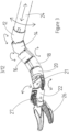
- a surgical instrument comprises a plurality of sections (12, 14, 16, 18, 20, 22) connected to a rigid shaft (24).
- the rigid shaft (24) is connected to an instrument base (not shown in figure 1 ).
- An instrument tip (26), also referred to as an end-effector herein, is connected to the section (22) furthest away from the rigid shaft (24).
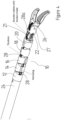
- a first section (12), as illustrated in figure 2 is fixedly connected to the rigid shaft (24) by way of a splined connection (12a).
- the first section (12) comprises a generally cylindrical body (12b) having the splined connection (12a) at one end thereof and a mounting feature (12c) at the other end thereof.
- the splined connection (12a) is 4mm long and comprises eight projections (12d) extending radially from a central lumen (12e). Each of the eight projections (12d) are evenly spaced apart with a length of 1.7mm measured from the central axis of the first section (12) and define a scallop (12f) between each adjacent pair of the eight projections (12d).
- Each scallop (12f) receives a tendon (not shown in figures 2a and 2b) with each tendon passing through the generally cylindrical body (12b) of the first section (12) through a respective hole (12g) arranged around the central lumen (12e).
- the splined connection (12a) further comprises a locking formation (12h) for restricting or preventing rotation of the first section (12) relative to the rigid shaft (24).
- the central lumen (12e) has a cylindrical profile and an internal diameter of between 1.5mm and 3mm.
- the mounting feature (12c) comprises an opposite pair of generally semi-circular tabs (12i) extending longitudinally away from the generally cylindrical body (12b).
- Each generally semi-circular tab (12i) has a radius of 0.5m and a thickness of between 0.5mm and 1.5mm.
- the generally semi-circular tabs (12i) are mounted at the extreme end of the body (12b) and define between them a flattened apex (12j) from which the generally cylindrical body (12b) is chamfered in both directions away from the end of the first section (12) to enable relative movement of an adjacent section (14).
- the angle of chamfer in each direction is ninety four degrees to enable the adjacent section (14) to hingedly rotate through eighty degrees relative to the first section (12).
- the rigid shaft (24), as shown in figure 1 comprises a hollow tube having an outer diameter of 5 mm and an inner diameter of 4 mm.
- the rigid shaft (24) is formed from stainless steel and is between 200mm and 300mm long.
- the first end (24a) of the rigid shaft (24) is configured to receive the splined connection (12a) of the first section (12) and restrict rotation of the splined connection (12a) of the first section (12) therein.
- the rigid shaft (24) is connected at the second end (12b) thereof to an instrument base (not shown in figure 1 or figure 2 ).
- the rigid shaft (24) is used to transmit linear translation and axial rotation motion from the instrument base to the end effector (26). All other degrees of freedom are controlled through use of the tendons that pass through the rigid shaft (24) to the surgical instrument sections (12, 14, 16, 18, 20, 22).
- the rigid shaft (24) further comprises a complimentary locking formation (24c) for cooperation with locking formation (12h) of the first section (12) to prevent rotation of the first section (12) relative to the rigid shaft (24).
- the second section (14), as illustrated in figure 2 , is hingedly connected to the first section (12).
- the second section (14) comprises a generally cylindrical body (14a) having a first end (14b) and a second end (14c).
- the first end (14b) of the second section (14) comprises a groove of triangular cross section (14d) for receiving the generally semi-circular tabs (12i) of the mounting formation (12c) of the first section (12).
- the profile of the cylindrical body (14a) of the second section (14) is chamfered away from the triangular groove (14d) in both directions towards the second end (14c).
- the angle of chamfer in each direction is ninety four degrees to enable relative hinged movement between the first section (12) and the second section (14).
- the second section (14) further comprises an internal lumen (14e) substantially similar to the internal lumen (12e) of the first section (12).
- the second end (14c) of the second section (14) comprises a mounting feature (14f) substantially the same as the mounting feature (12c) of the first section (12).
- a plurality of holes (14g) for receiving respective tendons pass longitudinally through the cylindrical body (14a) and surround the lumen (14e).
- the third and fourth sections (16, 18) are substantially the same as the second section (14) and connected together in a snake like formation.
- the sections (12, 14, 16, 18) can be arranged to provide hinged movement in any direction as necessary according to intended use of the surgical instrument (10).
- the second section (14) as illustrated in figure 2 shows the mounting formation (14e) and triangular groove (14d) aligned.
- the mounting formation (16a) and triangular groove (16b) are orientated at ninety degrees from one another. It will be appreciated that the orientation of the mounting formation (16a) and triangular groove (16b) can be selected based on the range of motion required for a particular application.
- each of the second, third and fourth sections are movable independently of one another to provide maximum dexterity.
- embodiments of the invention require less dexterity and two or more adjacent sections are locked together causing such sections to move in unison.
- Figure 3 illustrates the degrees of freedom of movement of a surgical instrument (10) according to aspects of the invention.
- the arrows shown indicate the general direction of movement of each component of the surgical instrument (10).
- the rigid shaft (24) imparts translational movement and axial rotation to the surgical instrument (10). None of the sections (12, 14, 16, 18, 20, 22) or end effector (26) have the independent ability to translate or rotate around the axis of the surgical instrument (10).
- the first section (12) is positionally fixed relative to the rigid shaft (24).
- the second section (14) defines an elbow joint with the first section (12) and is hingedly movable relative to the first section (12) through an angular range of movement of eighty degrees.
- the third section (16) defines an elbow joint with the second section (14) and is hingedly movable relative to the second section (14) through an angular range of movement of eighty degrees.
- the fourth section (18) defines an elbow joint with the third section and is hingedly movable relative to the third section (16) through an angular range of movement of up to eighty degrees. In some embodiments the angular range of movement is sixty degrees.
- axial rotation is imparted into the end effector (26) by an axial rotational joint (29), as shown in figure 16 .
- the axial rotational joint (29) allows for two hundred and seventy degree axial rotation of the end effector (26).
- Axial rotation is imparted by way of a pair of tendons (not shown).
- an instrument comprising an axial rotational joint (29) adjacent to or integral with the end effector (26) further comprises a quadrilateral actuation mechanism (31) for opening and closing the jaws (33, 35).
- the quadrilateral mechanism comprises first and second arms (31a, 31b) connected to each of the jaws (33, 35) by a common pivot point (31c) and third and fourth arms (31d, 31e) respectively pivotally connected to the first and second arms (31a, 31b) and at a common pivot point (31f) acting as an anchor point for a drive tendon (31g).
- the drive tendon (31g) is operatively connected to a return spring (not shown) such that the jaws (33, 35) are biased in a closed configuration by the return spring.
- the fifth section (20) and sixth section together define part of the wrist joint of the surgical instrument (10).
- the fifth section (20) defines an elbow with the fourth section (18) and is hingedly movable relative to the fourth section (18).
- the fifth section (20) also defines a separate hinged joint (21) with the sixth section (22).
- the sixth section (22) is hingedly movable relative to the fifth section (20).
- the sixth section (22) defines a hinged connection (27) with an end effector (26) which is arranged perpendicular to the hinged connection between the fifth section (20) and sixth section (22).
- the hinged connection (27) between the sixth section (22) and end effector (26) and the hinged connection (21) between the fifth section (20) and sixth section (22) together define all DoF provided by the wrist joint.
- each of the sections (14, 16, 18, 20, 22) is independently movable relative to adjacent sections (14, 16, 18, 20, 22). This arrangement enables the surgical instrument (10) to be manoeuvred in a snake like manner to provide an optimised motion path for a surgeon during surgery.
- sections (14, 16, 18, 20) may be coupled to adjacent sections (12, 14, 16, 18, 20) such that one or more adjacent sections (14, 16, 18, 20) move together.
- tendons (28) passing through the lumen in the rigid shaft (24) and through respective holes in each section (12, 14, 16, 18, 20, 22) and end effector (26) are used to provide independent control to each respective section (12, 14, 16, 18, 20, 22) and end effector (26).
- Each section (12, 14, 16, 18, 20, 22) and end effector (26) is associated with an antagonistic pair of tendons (28).
- antagonistic it is meant that tensioning one of the pair of antagonistic tendons will result in movement of a section (12, 14, 16, 18, 20, 22) or end effector (26) in one direction and tensioning of the other of the pair of antagonistic tendons will result in movement of a section (12, 14, 16, 18, 20, 22) or end effector (26) in the other direction.
- Each one of a pair of antagonistic tendons (28) is terminated at a section (14, 16, 18, 20, 22) or end effector (26). Termination of tendons (28) is effected by collapsing the tendon holes (12g - for the first section) through the relevant section (14, 16, 18, 20, 22) or end effector (26) to prevent further movement of the tendons (28) relative to that section (14, 16, 18, 20, 22) or end effector (26).
- Tendons (28) associated with control of sections (18, 20, 22) located nearer to the end effector (26) pass through the neutral axis of the bending plane of adjacent sections to reduce motion coupling between adjacent sections.
- tendons (28) provide passive control to those sections not associated with a pair of terminated antagonistic tendons (28).
- Such an embodiment might be used in a surgical instrument used for. cutting tissue where high manual dexterity is not needed. Surgical instruments used for manipulating tissue or using a needle and thread need a greater degree of manual dexterity.
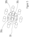
- the lumens (12e, 14e, for example) in each section in some embodiments are fitted with a multi-lumen polytetrafluoroethylene (PTFE) catheter (30) as shown in figure 5 .
- the PTFE catheter (30) comprises a generally cylindrical rod (30a) having a plurality of lumens (30b) therethrough surrounding a central lumen (30c).
- Each of the plurality of lumens (30b) is 40 configured to receive a tendon for independent control of the end effector (26).
- the PTFE catheter (30) assists ire keeping the tendons for controlling the end effector passing therethrough as close as possible to the bending axis of the surgical instrument (10) to prevent a joint coupling effect between adjacent hingedly connected components of the surgical instrument (10).
- the PTFE catheter (30) additionally assists to reduce friction between adjacent tendons (28) and between tendons (28) and elbow joints.
- the tendons for the end effector (26) are shrouded by Bowden cables (28a), i.e. a flexible cable used to transmit mechanical force or energy by the movement of an inner cable relative to a hollow outer cable housing.
- Bowden cables (28a) i.e. a flexible cable used to transmit mechanical force or energy by the movement of an inner cable relative to a hollow outer cable housing.
- the PTFE catheter (30) is only needed if the end effector (26) comprises an articulated tool providing a further degree of freedom of positioning such as a grasper or scissors.
- the lumen (12e, 14e, for example) through each of the elbow joints can receive a flexible suction and/or irrigation tube (32) as shown in figure 6 .
- the flexible tube (32) is intended for use with either a monopolar knife or bipolar tweezers. Both types of tool require electricity to be supplied to the tip of the end effector (26). In the case of a monopolar tool, electricity is conveyed to the tip of the end effector (26) through the metal structure of the end effector (26). In the case of bipolar tweezers, electricity is conveyed to one side of the tweezers by the metal structure of the end effector (26). An electrical wire conveys electricity from the electrified tweezer side to the other tweezer side which is otherwise electrically isolated from the first side.
- the instrument base (34), as shown in figures 7a to 7d , comprises six motor couplings (36) each associated with respective capstans (38) around which individual tendons (28) are wound.
- Each motor coupling (36) on the instrument base (34) comprises a plurality of holes (40) for engagement with a plurality of corresponding pins (42) on a corresponding motor coupling (44) on a motor pack (46).
- Each motor coupling (44) on the motor pack (46) is associated with a respective independently driven motor.
- Each motor coupling (36) on the instrument base (34) is made from medical grade polyetheretherketon.
- the motor couplings (36) on the instrument base (34) are each coupled to respective corresponding motor couplings (44) on the motor pack (46) by rotating the motor couplings (36, 44) on either the instrument base (34) or motor pack (44) until the pins (42) on the motor couplings (44) on the motor coupling (46) engage with the holes (40) on the motor couplings (36) on the instrument base (34).
- Either or both of the motor couplings (36, 44) on the instrument base (34) and/or motor pack (46) are spring loaded to provide a positive engagement between the pins (42) on the motor couplings (44) on the motor pack (46) and the holes (40) on the motor couplings (36) on the instrument base (34).
- the instrument base (34) is secured to the motor pack (46) by inserting a locking pin (48) through a locking feature (50) on the motor pack (46) and into a corresponding locking feature (52) on the instrument base (34).
- Each motor coupling (36) on the instrument base (34) is associated with driving a capstan (38) to wind a tendon (28) for operating a section (12, 14, 16, 18, 20, 22) or end effector (26).
- An idle gear (55) (as shown in figure 7b ) is positioned between two capstans.
- a gear ratio of 2:1 to between the two capstans reflect the tendon travel difference between the two parallel joints to enable a single motor to drive the two capstans to achieve the desired actuation of the two parallel joints between sections (12, 14, 16).
- the joints between sections (16, 18, 20) are coupled in the same way by another idle gear on the other side of the instrument base (34).
- a translation gear (54) is attached to a motor output shaft directly.
- the gear (54) drives the instrument and motor pack moving along a rack (not shown) for linear translation.
- the end effector (26) can be a grasper, needle driver or scissors, for example and is coupled to the final section (20) of the surgical instrument (10) by way of an end effector (22).
- the end effector (26) is coupled to the final section (22) of the surgical instrument (10) by way of a hinge arrangement orientated perpendicularly to the hinged coupling between the fourth section (18) and final section (22).
- the hinged coupling between the final section (22) and end effector (26) is also perpendicular to the hinged coupling between the fifth section (20) and sixth section (22).
- Examples of end effector (26) disclosed herein include: i) a wristed grasper - seven degrees of freedom tool with grasper jaws which can be either straight or curved and which is used to manipulate tissue, ii) wristed scissors - seven degrees of freedom wristed tool with scissor blades used to cut tissue with either curved or straight blades, iii) non-wristed scissors - six degrees of freedom tool with scissor blades used to cut tissue with either curved or straight blades, iv) wristed needle driver - seven degrees of freedom tool with straight short jaws having a diamond shaped knurling to grip onto surgical needles, v) non-wristed needle driver - six degrees of freedom tool with straight short jaws having a diamond shaped knurling to grip onto surgical needles, vi) monopolar knife with suction/irrigation - a four degree of freedom multi-functional tool without wrist joint and jaws used for tissue re-section, tissue cauterization, suction of liquid
- a monopolar tool i.e. a knife
- electrocautery tissue cut and cauterization
- suction and irrigation Such a tool is multi-functional and enables a surgeon to excise and cauterise tissue while at the same time removing smoke by way of the suction function. Irrigation is used to wash the wound and suction can again be used to clear the wound from fluids, i.e. blood and saline.
- a particular example of end effector (26) is a jawed grasper (400) having a pair of opposed jaws.
- Each jaw (400a) of the end effector (26) is formed of unitary construction and comprises a gripping surface (400b) defined by the internal surface of an elongate member (400c).
- the elongate member (400c) further comprises a recess (400d) opposite the gripping surface (400b).
- the recess (400d) extends longitudinally along the elongate member (400c) and is configured to receive a sensor (402) shaped to correspond with the overall profile of the elongate member (400c).
- the elongate member (400c) is joined to a mounting boss (400e) defined by two spaced apart plates (400f, 400g) having a gap therebetween.
- a mounting hole (400h) passes through the mounting boss (400e) for receiving a pivot (not shown).
- the sensor (402) has a first insertion portion (402a) and a second insertion portion (402b) which are cooperable with a respective first receiving portion (400i) and second receiving portion (400j) of the elongate member (400c) of the jaw (400a).
- the sensor (402) can be a force sensor, temperature sensor, tactile sensor, for example.
- the needle driver (500) is fixedly coupled to the final section (20) of the surgical instrument (10) by way of a splined connection (20a).
- the needle driver (500) comprises a body (502) having a mounting arrangement (504) co-operable with each of a pair of opposed grasping jaws (506, 508).
- the mounting arrangement (504) facilitates pivotal movement of a mounting part of each jaw (506, 508) to permit the jaws (506, 508) to open and close by way of a pin (510) passing through each jaw (506, 508) and the body (502).
- each jaw there are two pins (510), one for each jaw (506, 508), which are spaced apart laterally and positioned adjacent the edge of the body (502) and terminate in a groove (512) on each of opposing sides of the body (502).
- the teeth (512), as better illustrated in figure 15 are triangular shaped and disposed in alternate rows to permit interlocking of the teeth (512) when the jaws (506, 508) are closed.
- Each tooth (512) has a base that measures 0.25mm, a height of 0.5mm and a width of 0.35mm.
- the teeth are placed in rows spaced 0.47mm apart. Every row of teeth presents five teeth. Alternating the position of the teeth ensures that the teeth from a first jaw (506) fall between spaced between neighbouring teeth (512) on the second jaw (508).
- the tip of the needle driver (500) features a nose (514) that is used to retain the thread of a suture (518) during knot tying thus preventing escape of the suture from the jaws (506, 508).
- the nose (514) comprises a bulbous end at the distal end of each jaw (506, 508).
- the proximal end of the jaws (506, 508) features a disc (516) having an outer diameter greater than the diameter of the instrument shaft. The disc (516) prevents the suture thread from wrapping around the instrument shaft.
- the profile of the jaws (506, 508) is rounded in some embodiments.
- Movement of the jaws (506, 508) is controlled by a tendon (514) and a spring (516).
- the jaws (506, 508) are biased in an open position by the spring (516).
- the spring (514) tension is overcome by tensioning the tendon (514) to close the jaws (506, 508).
- the motor pack (46) is selectively mountable to a robotic arm (100) or to a port as described in further detail below.
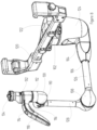
- the robotic arm (100), as shown in figure 8 comprises six electromagnetically braked joints (102, 104, 106, 108, 110, 112).
- Each electromagnetically braked joint (102, 104, 106, 108, 110, 112) comprises an electromagnetic brake and a backlash-free differential drive equipped with an absolute angle joint encoder.
- the electromagnetic brakes are biased in an on position and releasable by depression of two operation switches (114, 116) located on a handle (118).
- the robotic arm (100) is mountable to a hospital bed by way of a mounting formation (120) coupled to the robotic arm (100).
- the mounting formation (120) is coupled to an anchor (122).
- the anchor (122) is coupled to a shoulder (124) by way of a first electromagnetically braked joint (102).
- the anchor (122) provides horizontal rotation relative to the shoulder (124).
- the shoulder (124) is coupled to a horizontal shaft (126) by way of a second electromagnetically braked joint (104).
- the shoulder (124) provides pivotal rotation relative to the horizontal shaft (126) in the direction of the longitudinal axis of the horizontal shaft (126).
- the horizontal shaft (126) extends through a third electromagnetically braked joint (106).
- the horizontal shaft (126) provides rotational positioning relative to the shoulder (124).
- the opposite end of the horizontal shaft (126) is coupled to a fourth electromagnetically braked joint (108).
- the fourth electromagnetically braked joint (108) is coupled to a vertical shaft (128).
- the vertical shaft (128) provides rotational positioning relative to the horizontal shaft (126).
- the vertical shaft (128) is coupled at the other end to a fifth electromagnetically braked joint (110).
- the fifth electromagnetically braked joint (110) is coupled to an elbow (130).
- the elbow (130) provides rotational positioning around a horizontal axis parallel to the horizontal axis of the horizontal shaft (126).
- the elbow (130) is coupled to a sixth electromagnetically braked joint (112) at the other end thereof.
- the sixth electromagnetically braked joint (112) is coupled to the handle (118).
- the handle is free to rotate around a vertical axis in order to position an adaptor (132) coupled to the handle (118).
- the adaptor (132) mounts the motor pack (46) and consequently the surgical instrument (10) to the robotic arm (100).
- the robotic arm (100) is mounted to a standard operating table by way of the mounting formation (120) which clamps the robotic arm (100) to the side rails of the standard operating table.
- the robotic arm (100) and surgical instrument (10) are both electrically powered from a mains supply power outlet through an AC/DC power adaptor.
- the power supply controls each of the electromagnetically braked joints (102, 104, 106, 108, 110, 112) with electromagnets associated with each being locked in place unless the operation switches (114, 116) on the handle (118) are depressed.
- the differential driver's output shaft will have a trivial relative rotation to the driver's body if a force is applied to the arm's end-effector.
- Such rotation can be measured by the joint angle encoder and consequently the torque on the differential drive caused by the force on the end-effector can be calculated considering the stiffness of the differential drive.
- the magnitude and direction of the force on the end-effector can be calculated.
- the combination of an electromagnetic brake with a backlash-free differential drive has the advantage of small footprint and large output torque comparing to the conventional solutions: 1. combination of a motor and a differential drive, in which the motor has much smaller holding torque comparing to the same size brake; 2. only using brake without differential drive, in which the output torque is less and the footprint is larger than our solution.
- a motor pack (46) is mounted to the adaptor (132) and a surgical instrument (10) is coupled to the motor pack (46), power is applied to the motor pack by way of a mains power supply.
- the motor pack (46) is controlled by a robot control system (200) as illustrated in figure 9 .
- the robot control system (200) is powered by a separate mains power supply (202) and comprises a plurality of motor controller modules (204), four are shown in figure 9 , and a safety watchdog module (206).
- the safety watchdog (206) is connected between the mains power supply (202) and the plurality of motor controller modules (204).
- the robot control system (200) is connected between the robotic surgical instrument (100) and a computer system (208).
- the robot control system (200) is further provided with an emergency stop button (210) for cutting all power to the robot control system (200) and thus the surgical instrument (10).
- a master manipulator (212) is connected to the computer system (208).
- the computer system (208) interprets movement of the master manipulator (212) to determine the desired action of the surgical instrument (10) and sends appropriate instructions to the robot control system (200) via a RS-485 bus to drive the plurality of motor controllers (204).
- the safety watchdog module (206) monitors a number of parameters of the robot control system (200) and/or surgical instrument (10) such as temperature and motor current for example. If the safety watchdog module (206) detects that a parameter has deviated from a pre-determined range or exceeded a pre-determined threshold, the safety watchdog module (206) will cut all power to the motor controller modules (204) to prevent erroneous operation and/or damage/injury to a patient. The safety watchdog module (206) also listens to communication between the computer system (208) and robot control system (200) and between the robot control system (200) and the surgical instrument (10). If instructions are detected that fall outside of accepted operating parameters the safety watchdog module (206) will cut all power to the robot control system (200) to prevent erroneous operation and/or damage/injury to a patient.
- the safety watchdog module (206) is a modular component that plugs into a motherboard (214).
- Each motor controller module (204) is also a modular component that plugs into the motherboard (214).
- Each motor controller module (204) can control up to two motors and the motherboard (214) can accommodate up to four motor controller modules (204) allowing connection of up to eight motors for driving the robotic surgical instrument (100).
- This disclosure is not intended to be limiting; other embodiments may be capable of accommodating further motor control modules and each motor control module may be capable of controlling one, two or more motors.
- the adaptor (132) includes an electrical connector (134) which can supply power and control signals via the internal wiring of the robotic arm (100).
- the motor pack (46) can be powered and controlled via either the electrical connection (134) or independent cables.
- a three dimensional boundary space or spatial threshold is defined prior to commencing surgery.
- the three dimensional boundary space is defined by moving the robotic arm (100) through a series of spatial points and recording each spatial point as a boundary point.
- the robotic arm during surgery is only permitted to move within the three dimensional boundary and is automatically locked should it hit, or in some instances approach, the three dimensional boundary.
- the robotic arm (100) comprises a rotary encoder that monitors every movement of each of the electromagnetically braked joints (102, 104, 106, 108, 112) and the surgical instrument end effector (22). Each movement is recorded as a data point relative to a respective origin point.
- the rotary encoder permits each electromagnetically braked joint (102, 104, 106, 108, 110, 112) and thus the surgical instrument end effector (22) to move through each data point in reverse. Once each data point is determined as being equal to a respective origin point, each of the electromagnetically braked joints (102, 104, 106, 108, 110, 112) is fully released.
- force detection means are associated with each of the electromagnetically braked joints (102, 104, 106, 108, 110, 112).
- a processor equates a force applied by a surgeon to a master manipulator (212) to direction and unlocks the electromagnetically braked joints (102, 104, 106, 108, 110, 112) if it is determined that all of the electro magnetically braked joints (102, 104, 106, 108, 110, 112) and the surgical instrument end effector (22) would be moved away from the three-dimensional boundary.
- each of the electromagnetically braked joints (102, 104, 106, 108, 110, 112) and/or the end effector (22) would be moved towards or cross the three-dimensional boundary, each of the electromagnetically braked joints (102, 104, 106, 108, 110, 112) would remain locked and movement would be resisted.
- the protective sleeve (300) for use with surgical instruments (10) of embodiments of the invention is shown.
- the protective sleeve (300) comprises an elongate sheath (302) that has a first end (302a) and a second end (302b).
- the elongate sheath is formed from a thin plastic material and is flexible and compressible.
- the first end (302a) of the elongate sheath (302) is attachable to a surgical instrument by way of an attachment interface (304).
- the attachment interface may comprise a locking means such as a twist locking mechanism or snap fit interface or may be magnetic.
- the second end (302b) of the elongate sheath (302) defines an interface for attachment of an end closure (306) such as a duckbill valve or other type of suitable valve.
- the end closure (306) may be attached to the second end (302b) of the elongate sheath (302) by way of a locking means or magnetic attachment, for example.
- the end effector end of a surgical instrument (10) is inserted into the protective sleeve (300) after sterilisation.
- the protective sleeve (300) is attached to the surgical instrument (10) by way of the attachment interface (304).
- the surgical instrument (10) is inserted into a lumen of a port immediately prior to start of surgery.
- the magnet is used to align the surgical instrument (10) with the lumen of the port.
- the closure means (306) is sized appropriately to enable it to extend through the lumen of the port.
- the surgical instrument (100) Upon conclusion of surgery, the surgical instrument (100) is withdrawn from the patient and through the port into the protective sleeve (300). The surgical instrument passes back through the valve which closes once the surgical instrument is again fully enclosed by the protective sleeve (300). Prior to re-use, the surgical instrument is sterilised through autoclave, gas or radiation treatment and a new protective sleeve (300) is fitted to the surgical instrument (100). The used protective sleeve (300) is discarded as hazardous waste after surgery.
Landscapes
- Health & Medical Sciences (AREA)
- Surgery (AREA)
- Life Sciences & Earth Sciences (AREA)
- Engineering & Computer Science (AREA)
- Animal Behavior & Ethology (AREA)
- Veterinary Medicine (AREA)
- Biomedical Technology (AREA)
- Heart & Thoracic Surgery (AREA)
- Medical Informatics (AREA)
- Molecular Biology (AREA)
- Nuclear Medicine, Radiotherapy & Molecular Imaging (AREA)
- General Health & Medical Sciences (AREA)
- Public Health (AREA)
- Robotics (AREA)
- Physics & Mathematics (AREA)
- Plasma & Fusion (AREA)
- Otolaryngology (AREA)
- Oral & Maxillofacial Surgery (AREA)
- Pathology (AREA)
- Surgical Instruments (AREA)
- Manipulator (AREA)
Applications Claiming Priority (4)
| Application Number | Priority Date | Filing Date | Title |
|---|---|---|---|
| GB1608997.1A GB2550575B (en) | 2016-05-23 | 2016-05-23 | Surgical instrument |
| GB1609002.9A GB2550577B (en) | 2016-05-23 | 2016-05-23 | Control system |
| GB1609030.0A GB2554846A (en) | 2016-05-23 | 2016-05-23 | Safety Device |
| PCT/GB2017/051436 WO2017203231A1 (en) | 2016-05-23 | 2017-05-23 | Surgical instrument, robotic arm and control system for a robotic arm |
Publications (2)
| Publication Number | Publication Date |
|---|---|
| EP3463155A1 EP3463155A1 (en) | 2019-04-10 |
| EP3463155B1 true EP3463155B1 (en) | 2024-02-07 |
Family
ID=58772598
Family Applications (1)
| Application Number | Title | Priority Date | Filing Date |
|---|---|---|---|
| EP17725763.1A Active EP3463155B1 (en) | 2016-05-23 | 2017-05-23 | Surgical instrument, robotic arm and control system for a robotic arm |
Country Status (7)
| Country | Link |
|---|---|
| US (1) | US20200038121A1 (enExample) |
| EP (1) | EP3463155B1 (enExample) |
| JP (2) | JP2019518580A (enExample) |
| CN (4) | CN115089299A (enExample) |
| AU (1) | AU2017270904A1 (enExample) |
| CA (1) | CA3035415A1 (enExample) |
| WO (1) | WO2017203231A1 (enExample) |
Families Citing this family (38)
| Publication number | Priority date | Publication date | Assignee | Title |
|---|---|---|---|---|
| US9050101B1 (en) | 2013-11-19 | 2015-06-09 | Ryan D. Smith | Surgical multi-tool and method of use |
| US10327767B2 (en) * | 2017-06-20 | 2019-06-25 | Ethicon Llc | Control of motor velocity of a surgical stapling and cutting instrument based on angle of articulation |
| US20230171304A1 (en) * | 2017-12-28 | 2023-06-01 | Cilag Gmbh International | Method of robotic hub communication, detection, and control |
| EP3566670A1 (en) * | 2018-05-07 | 2019-11-13 | Koninklijke Philips N.V. | Safety system for surgical robot |
| WO2020014401A1 (en) * | 2018-07-10 | 2020-01-16 | Boards Of Regents Of The University Of Texas System | Articulable devices for in vivo tissue evaluation |
| US12194620B2 (en) | 2018-10-15 | 2025-01-14 | Oliver Crisipin Robotics Limited | Selectively flexible extension tool |
| US11702955B2 (en) | 2019-01-14 | 2023-07-18 | General Electric Company | Component repair system and method |
| CN110772335B (zh) * | 2019-04-25 | 2021-06-01 | 深圳市精锋医疗科技有限公司 | 手术器械 |
| US11696806B2 (en) | 2019-07-23 | 2023-07-11 | Verb Surgical Inc. | Strain wave gearing with input to output braking |
| EP4013328A4 (en) | 2019-08-16 | 2023-08-09 | Divyze, Inc. | Electrosurgical energy adapter, electrosurgical energy control, and surgical multi-tool |
| US12405187B2 (en) | 2019-10-04 | 2025-09-02 | General Electric Company | Insertion apparatus for use with rotary machines |
| CN110823433B (zh) * | 2019-10-18 | 2021-10-15 | 中国直升机设计研究所 | 一种用于旋翼载荷测量的五自由度装置 |
| CN112704565B (zh) * | 2019-10-25 | 2025-07-11 | 新加坡国立大学 | 操控支承装置及操控支承系统 |
| GB2592401B (en) | 2020-02-27 | 2024-06-05 | Cmr Surgical Ltd | Watchdog circuitry of a surgical robot arm |
| CN115315226A (zh) * | 2020-03-24 | 2022-11-08 | 奥瑞斯健康公司 | 用于外科机器人装置的热信息传送系统和方法 |
| EP3900650A1 (en) * | 2020-04-23 | 2021-10-27 | Microsure B.V. | Surgical robotic system comprising spherical wrist |
| US12091981B2 (en) | 2020-06-11 | 2024-09-17 | General Electric Company | Insertion tool and method |
| JPWO2021255877A1 (enExample) * | 2020-06-17 | 2021-12-23 | ||
| WO2022001993A1 (en) | 2020-06-30 | 2022-01-06 | Precision Robotics (Hong Kong) Limited | Surgical robotic arm, flexible arm and flexible joint |
| US11638582B2 (en) * | 2020-07-28 | 2023-05-02 | Cilag Gmbh International | Surgical instruments with torsion spine drive arrangements |
| WO2022037075A1 (zh) * | 2020-08-21 | 2022-02-24 | 北京术锐技术有限公司 | 连接适配器、连接组件和手术机器人系统 |
| CA3190855A1 (en) | 2020-08-27 | 2022-03-03 | Joe Mccann | Radiopharmaceutical and methods |
| EP3970651A1 (en) * | 2020-09-16 | 2022-03-23 | Covidien LP | Multi-function surgical instruments |
| JP1698566S (enExample) | 2020-12-07 | 2021-11-01 | ||
| US12416800B2 (en) | 2021-01-08 | 2025-09-16 | General Electric Company | Insertion tool |
| US12504616B2 (en) | 2021-01-08 | 2025-12-23 | General Electric Company | Insertion tool |
| CN113040916B (zh) * | 2021-03-13 | 2022-09-30 | 极限人工智能有限公司 | 一种万向手术装置及医疗器械 |
| CN112692862B (zh) * | 2021-03-25 | 2021-10-26 | 成都博恩思医学机器人有限公司 | 一种用于机器人的多自由度器械 |
| CN113208734B (zh) * | 2021-05-13 | 2022-02-22 | 德智鸿(上海)机器人有限责任公司 | 手术机器人及定位方法 |
| USD995776S1 (en) | 2021-06-07 | 2023-08-15 | Precision Robotics Ltd | Surgical instrument |
| WO2023272375A1 (en) * | 2021-06-20 | 2023-01-05 | Titan Medical Inc. | Method for controlling an articulating instrument |
| CN113386119B (zh) * | 2021-06-30 | 2022-05-27 | 哈尔滨工业大学(深圳) | 一种可实现伸缩和偏转的绳驱柔性机械臂关节 |
| CN113952036B (zh) * | 2021-09-09 | 2022-09-02 | 杭州微引科技有限公司 | 一种手术机械手执行集成头及手术机械手装置 |
| EP4415933A4 (en) * | 2021-10-12 | 2025-07-02 | Shanghai Flexiv Robotics Tech Co Ltd | SAFETY SYSTEM, JOINT ASSEMBLY HAVING A SAFETY SYSTEM, AND ROBOT HAVING A JOINT ASSEMBLY |
| CN113729927B (zh) * | 2021-11-05 | 2022-02-08 | 极限人工智能(北京)有限公司 | 有源手术器械、分体式手术装置及软组织机器人 |
| GB2614076B (en) * | 2021-12-21 | 2024-05-15 | Prec Robotics Limited | An articulated member |
| CN114406995B (zh) * | 2022-01-29 | 2024-07-09 | 中国航空制造技术研究院 | 一种蛇形机械臂及稳定工作方法 |
| CN115500938B (zh) * | 2022-09-28 | 2025-11-14 | 河北凯恩德软件开发有限公司 | 一种锁定或释放医疗器械的装置及方法 |
Family Cites Families (49)
| Publication number | Priority date | Publication date | Assignee | Title |
|---|---|---|---|---|
| JPH08224242A (ja) * | 1995-02-22 | 1996-09-03 | Olympus Optical Co Ltd | 医療用装置 |
| US6786896B1 (en) * | 1997-09-19 | 2004-09-07 | Massachusetts Institute Of Technology | Robotic apparatus |
| WO2000041614A1 (en) * | 1999-01-19 | 2000-07-20 | Tyco Healthcare Group Lp | Sheath and applicator for surgical instrument |
| US20020147382A1 (en) * | 2001-01-23 | 2002-10-10 | Neisz Johann J. | Surgical articles and methods |
| US6817974B2 (en) * | 2001-06-29 | 2004-11-16 | Intuitive Surgical, Inc. | Surgical tool having positively positionable tendon-actuated multi-disk wrist joint |
| US20060199999A1 (en) * | 2001-06-29 | 2006-09-07 | Intuitive Surgical Inc. | Cardiac tissue ablation instrument with flexible wrist |
| US7410483B2 (en) * | 2003-05-23 | 2008-08-12 | Novare Surgical Systems, Inc. | Hand-actuated device for remote manipulation of a grasping tool |
| JP4472365B2 (ja) * | 2004-01-23 | 2010-06-02 | オリンパス株式会社 | 医療器具保持装置 |
| US20070049973A1 (en) * | 2005-08-29 | 2007-03-01 | Vascular Control Systems, Inc. | Method and device for treating adenomyosis and endometriosis |
| US8597280B2 (en) * | 2006-06-13 | 2013-12-03 | Intuitive Surgical Operations, Inc. | Surgical instrument actuator |
| US20080058851A1 (en) * | 2006-09-01 | 2008-03-06 | Edelstein Peter Seth | Method and apparatus for assisting in the introduction of surgical implements into a body |
| JP5074069B2 (ja) * | 2007-03-29 | 2012-11-14 | オリンパスメディカルシステムズ株式会社 | 多関節湾曲機構及び多関節湾曲機構を備えた医療器具 |
| US9271751B2 (en) * | 2007-05-29 | 2016-03-01 | Ethicon Endo-Surgery, Llc | Ultrasonic surgical system |
| EP2011442A1 (en) * | 2007-07-02 | 2009-01-07 | Berner Fachhochschule, Technik und Informatik (TI) | Pliers for separating two adjacent bone segments |
| JP5028219B2 (ja) * | 2007-10-30 | 2012-09-19 | オリンパスメディカルシステムズ株式会社 | マニピュレータ装置および医療機器システム |
| GB2466180B (en) * | 2008-12-05 | 2013-07-10 | Surgical Innovations Ltd | Surgical instrument, handle for a surgical instrument and surgical instrument system |
| GB0910951D0 (en) * | 2009-06-24 | 2009-08-05 | Imp Innovations Ltd | Joint arrangement |
| JP5375522B2 (ja) * | 2009-10-27 | 2013-12-25 | トヨタ自動車株式会社 | ロボットアーム制御装置、その制御方法及びプログラム |
| KR20110047926A (ko) * | 2009-10-30 | 2011-05-09 | 주식회사 이턴 | 수술용 인스트루먼트의 죠 구조 |
| US9089351B2 (en) * | 2010-02-12 | 2015-07-28 | Intuitive Surgical Operations, Inc. | Sheath for surgical instrument |
| WO2011116335A2 (en) * | 2010-03-18 | 2011-09-22 | SPI Surgical, Inc. | Introducer device |
| US9033998B1 (en) * | 2010-05-13 | 2015-05-19 | Titan Medical Inc. | Independent roll wrist mechanism |
| US20120065645A1 (en) * | 2010-09-10 | 2012-03-15 | Mark Doyle | Protective sheath |
| WO2012106555A2 (en) * | 2011-02-02 | 2012-08-09 | Filiciotto Sam | Surgical systems and methods thereof |
| US8578810B2 (en) * | 2011-02-14 | 2013-11-12 | Intuitive Surgical Operations, Inc. | Jointed link structures exhibiting preferential bending, and related methods |
| JP6518403B2 (ja) * | 2011-02-18 | 2019-05-22 | インテュイティブ サージカル オペレーションズ, インコーポレイテッド | 融合及び切断用外科用器具とこれに関連する方法 |
| WO2012166807A1 (en) * | 2011-05-31 | 2012-12-06 | Intuitive Surgical Operations, Inc. | Surgical instrument with motor |
| US9622825B2 (en) * | 2011-11-28 | 2017-04-18 | National University Of Singapore | Robotic system for flexible endoscopy |
| US9211159B2 (en) * | 2011-12-02 | 2015-12-15 | Ethicon Endo-Surgery, Inc. | Surgical devices with intracorporeal elbow joint |
| JP2013163232A (ja) * | 2012-02-09 | 2013-08-22 | Canon Inc | ロボットアームの制御装置、ロボットアーム及びそのプログラム |
| EP2822484A4 (en) * | 2012-03-06 | 2015-11-18 | Briteseed Llc | SURGICAL TOOL WITH INTEGRATED SENSOR |
| CN104411266B (zh) * | 2012-04-27 | 2019-01-01 | 库卡实验仪器有限公司 | 机器人手术系统 |
| CN102744732B (zh) * | 2012-06-20 | 2015-05-27 | 东莞东聚电子电讯制品有限公司 | 一种蛇形机械臂 |
| CN107961076B (zh) * | 2012-08-15 | 2020-07-07 | 直观外科手术操作公司 | 使用者启动的手术安装平台的断开式离合 |
| DE102012018620B4 (de) * | 2012-09-13 | 2014-04-03 | Fraunhofer-Gesellschaft zur Förderung der angewandten Forschung e.V. | Sensorsystem zum Überwachen eines Objekts |
| JP6159075B2 (ja) * | 2012-11-01 | 2017-07-05 | 国立大学法人東京工業大学 | 鉗子マニピュレータ、および鉗子マニピュレータを備える鉗子システム |
| WO2014116782A1 (en) * | 2013-01-23 | 2014-07-31 | Cambridge Surgical Instruments, Inc. | Device for providing sensory feedback during surgical procedures |
| KR102046373B1 (ko) * | 2013-03-11 | 2019-11-20 | 삼성전자주식회사 | 와이어 감속기를 구비하는 복강경 수술기구 |
| CN105073045A (zh) * | 2013-03-13 | 2015-11-18 | 柯惠Lp公司 | 用于肺手术的钳式超声波探头 |
| KR20160008169A (ko) * | 2013-03-14 | 2016-01-21 | 에스알아이 인터내셔널 | 컴팩트 로봇 리스트 |
| GB201304572D0 (en) * | 2013-03-14 | 2013-05-01 | Rolls Royce Plc | Multi-jointed arm assembly |
| CN103431913B (zh) * | 2013-09-12 | 2015-04-29 | 哈尔滨工业大学 | 微创外科机器人手术微器械 |
| KR102111621B1 (ko) * | 2013-11-05 | 2020-05-18 | 삼성전자주식회사 | 매니퓰레이터 |
| US9452532B2 (en) * | 2014-01-27 | 2016-09-27 | Panasonic Intellectual Property Management Co., Ltd. | Robot, device and method for controlling robot, and computer-readable non-transitory recording medium |
| FR3019953B1 (fr) * | 2014-04-09 | 2016-05-06 | Staubli Sa Ets | Procede de commande d'un robot multi-axes et robot pour la mise en oeuvre d'un tel procede |
| CN104434318B (zh) * | 2014-12-17 | 2016-05-25 | 上海交通大学 | 一种微创手术机器人的手术器械末端结构 |
| CN105014689A (zh) * | 2015-07-28 | 2015-11-04 | 上海交通大学 | 运动解耦的绳驱动连续体机械臂及机器人 |
| CN105150219B (zh) * | 2015-09-28 | 2017-06-23 | 哈尔滨工业大学深圳研究生院 | 一种基于绳索驱动的超冗余柔性机械臂 |
| GB2592401B (en) * | 2020-02-27 | 2024-06-05 | Cmr Surgical Ltd | Watchdog circuitry of a surgical robot arm |
-
2017
- 2017-05-23 CA CA3035415A patent/CA3035415A1/en not_active Abandoned
- 2017-05-23 CN CN202210665882.8A patent/CN115089299A/zh active Pending
- 2017-05-23 CN CN201780038949.2A patent/CN109561935B/zh active Active
- 2017-05-23 JP JP2019514869A patent/JP2019518580A/ja active Pending
- 2017-05-23 EP EP17725763.1A patent/EP3463155B1/en active Active
- 2017-05-23 WO PCT/GB2017/051436 patent/WO2017203231A1/en not_active Ceased
- 2017-05-23 CN CN202210667526.XA patent/CN115089306B/zh active Active
- 2017-05-23 CN CN202210667520.2A patent/CN115089242A/zh active Pending
- 2017-05-23 AU AU2017270904A patent/AU2017270904A1/en not_active Abandoned
- 2017-05-23 US US16/303,392 patent/US20200038121A1/en not_active Abandoned
-
2022
- 2022-05-31 JP JP2022088190A patent/JP2022122953A/ja active Pending
Also Published As
| Publication number | Publication date |
|---|---|
| CN115089242A (zh) | 2022-09-23 |
| CN115089306B (zh) | 2025-09-16 |
| JP2019518580A (ja) | 2019-07-04 |
| CA3035415A1 (en) | 2017-11-30 |
| AU2017270904A1 (en) | 2019-01-17 |
| US20200038121A1 (en) | 2020-02-06 |
| CN115089299A (zh) | 2022-09-23 |
| CN115089306A (zh) | 2022-09-23 |
| WO2017203231A1 (en) | 2017-11-30 |
| EP3463155A1 (en) | 2019-04-10 |
| CN109561935A (zh) | 2019-04-02 |
| CN109561935B (zh) | 2022-07-22 |
| JP2022122953A (ja) | 2022-08-23 |
Similar Documents
| Publication | Publication Date | Title |
|---|---|---|
| EP3463155B1 (en) | Surgical instrument, robotic arm and control system for a robotic arm | |
| US12257012B2 (en) | Surgical instrument with retaining feature for cutting element | |
| US20260020899A1 (en) | Surgical instruments having non-linear cam slots | |
| CN113226209B (zh) | 用于外科器械的远侧闭合机构 | |
| EP3170462B1 (en) | Articulating ultrasonic surgical instruments and systems | |
| EP3079610B1 (en) | Surgical device for grasping and shearing | |
| BR112012011424B1 (pt) | instrumento cirúrgico | |
| GB2550575B (en) | Surgical instrument | |
| CN112739274A (zh) | 关节运动式刀片部署 | |
| CN113679450A (zh) | 铰接超声手术仪器和系统 | |
| US20260047858A1 (en) | Replaceable surgical scissor blades for surgical instruments | |
| GB2554846A (en) | Safety Device | |
| GB2550577A (en) | Control system | |
| HK40006976B (en) | Surgical instrument, robotic arm and control system for a robotic arm | |
| HK40006976A (en) | Surgical instrument, robotic arm and control system for a robotic arm | |
| JP7439116B2 (ja) | ハサミスリーブアセンブリの保護 | |
| GB2578513A (en) | Surgical instrument | |
| US20260026868A1 (en) | Replaceable surgical scissor blades for surgical instruments | |
| WO2023023045A1 (en) | Surgical instrument shears |
Legal Events
| Date | Code | Title | Description |
|---|---|---|---|
| STAA | Information on the status of an ep patent application or granted ep patent |
Free format text: STATUS: UNKNOWN |
|
| STAA | Information on the status of an ep patent application or granted ep patent |
Free format text: STATUS: THE INTERNATIONAL PUBLICATION HAS BEEN MADE |
|
| PUAI | Public reference made under article 153(3) epc to a published international application that has entered the european phase |
Free format text: ORIGINAL CODE: 0009012 |
|
| STAA | Information on the status of an ep patent application or granted ep patent |
Free format text: STATUS: REQUEST FOR EXAMINATION WAS MADE |
|
| 17P | Request for examination filed |
Effective date: 20181206 |
|
| AK | Designated contracting states |
Kind code of ref document: A1 Designated state(s): AL AT BE BG CH CY CZ DE DK EE ES FI FR GB GR HR HU IE IS IT LI LT LU LV MC MK MT NL NO PL PT RO RS SE SI SK SM TR |
|
| AX | Request for extension of the european patent |
Extension state: BA ME |
|
| DAV | Request for validation of the european patent (deleted) | ||
| DAX | Request for extension of the european patent (deleted) | ||
| REG | Reference to a national code |
Ref country code: HK Ref legal event code: DE Ref document number: 40006976 Country of ref document: HK |
|
| STAA | Information on the status of an ep patent application or granted ep patent |
Free format text: STATUS: EXAMINATION IS IN PROGRESS |
|
| 17Q | First examination report despatched |
Effective date: 20220527 |
|
| RAP3 | Party data changed (applicant data changed or rights of an application transferred) |
Owner name: IP2IPO INNOVATIONS LIMITED |
|
| RAP3 | Party data changed (applicant data changed or rights of an application transferred) |
Owner name: IP2IPO INNOVATIONS LIMITED |
|
| GRAP | Despatch of communication of intention to grant a patent |
Free format text: ORIGINAL CODE: EPIDOSNIGR1 |
|
| STAA | Information on the status of an ep patent application or granted ep patent |
Free format text: STATUS: GRANT OF PATENT IS INTENDED |
|
| INTG | Intention to grant announced |
Effective date: 20230908 |
|
| GRAS | Grant fee paid |
Free format text: ORIGINAL CODE: EPIDOSNIGR3 |
|
| GRAA | (expected) grant |
Free format text: ORIGINAL CODE: 0009210 |
|
| STAA | Information on the status of an ep patent application or granted ep patent |
Free format text: STATUS: THE PATENT HAS BEEN GRANTED |
|
| AK | Designated contracting states |
Kind code of ref document: B1 Designated state(s): AL AT BE BG CH CY CZ DE DK EE ES FI FR GB GR HR HU IE IS IT LI LT LU LV MC MK MT NL NO PL PT RO RS SE SI SK SM TR |
|
| REG | Reference to a national code |
Ref country code: GB Ref legal event code: FG4D |
|
| REG | Reference to a national code |
Ref country code: CH Ref legal event code: EP |
|
| REG | Reference to a national code |
Ref country code: IE Ref legal event code: FG4D |
|
| REG | Reference to a national code |
Ref country code: DE Ref legal event code: R096 Ref document number: 602017078976 Country of ref document: DE |
|
| REG | Reference to a national code |
Ref country code: LT Ref legal event code: MG9D |
|
| REG | Reference to a national code |
Ref country code: NL Ref legal event code: MP Effective date: 20240207 |
|
| PG25 | Lapsed in a contracting state [announced via postgrant information from national office to epo] |
Ref country code: IS Free format text: LAPSE BECAUSE OF FAILURE TO SUBMIT A TRANSLATION OF THE DESCRIPTION OR TO PAY THE FEE WITHIN THE PRESCRIBED TIME-LIMIT Effective date: 20240607 |
|
| PG25 | Lapsed in a contracting state [announced via postgrant information from national office to epo] |
Ref country code: LT Free format text: LAPSE BECAUSE OF FAILURE TO SUBMIT A TRANSLATION OF THE DESCRIPTION OR TO PAY THE FEE WITHIN THE PRESCRIBED TIME-LIMIT Effective date: 20240207 |
|
| PG25 | Lapsed in a contracting state [announced via postgrant information from national office to epo] |
Ref country code: GR Free format text: LAPSE BECAUSE OF FAILURE TO SUBMIT A TRANSLATION OF THE DESCRIPTION OR TO PAY THE FEE WITHIN THE PRESCRIBED TIME-LIMIT Effective date: 20240508 |
|
| REG | Reference to a national code |
Ref country code: AT Ref legal event code: MK05 Ref document number: 1654877 Country of ref document: AT Kind code of ref document: T Effective date: 20240207 |
|
| PG25 | Lapsed in a contracting state [announced via postgrant information from national office to epo] |
Ref country code: RS Free format text: LAPSE BECAUSE OF FAILURE TO SUBMIT A TRANSLATION OF THE DESCRIPTION OR TO PAY THE FEE WITHIN THE PRESCRIBED TIME-LIMIT Effective date: 20240507 Ref country code: HR Free format text: LAPSE BECAUSE OF FAILURE TO SUBMIT A TRANSLATION OF THE DESCRIPTION OR TO PAY THE FEE WITHIN THE PRESCRIBED TIME-LIMIT Effective date: 20240207 Ref country code: NL Free format text: LAPSE BECAUSE OF FAILURE TO SUBMIT A TRANSLATION OF THE DESCRIPTION OR TO PAY THE FEE WITHIN THE PRESCRIBED TIME-LIMIT Effective date: 20240207 |
|
| PG25 | Lapsed in a contracting state [announced via postgrant information from national office to epo] |
Ref country code: ES Free format text: LAPSE BECAUSE OF FAILURE TO SUBMIT A TRANSLATION OF THE DESCRIPTION OR TO PAY THE FEE WITHIN THE PRESCRIBED TIME-LIMIT Effective date: 20240207 |
|
| PG25 | Lapsed in a contracting state [announced via postgrant information from national office to epo] |
Ref country code: AT Free format text: LAPSE BECAUSE OF FAILURE TO SUBMIT A TRANSLATION OF THE DESCRIPTION OR TO PAY THE FEE WITHIN THE PRESCRIBED TIME-LIMIT Effective date: 20240207 |
|
| PG25 | Lapsed in a contracting state [announced via postgrant information from national office to epo] |
Ref country code: RS Free format text: LAPSE BECAUSE OF FAILURE TO SUBMIT A TRANSLATION OF THE DESCRIPTION OR TO PAY THE FEE WITHIN THE PRESCRIBED TIME-LIMIT Effective date: 20240507 Ref country code: NO Free format text: LAPSE BECAUSE OF FAILURE TO SUBMIT A TRANSLATION OF THE DESCRIPTION OR TO PAY THE FEE WITHIN THE PRESCRIBED TIME-LIMIT Effective date: 20240507 Ref country code: NL Free format text: LAPSE BECAUSE OF FAILURE TO SUBMIT A TRANSLATION OF THE DESCRIPTION OR TO PAY THE FEE WITHIN THE PRESCRIBED TIME-LIMIT Effective date: 20240207 Ref country code: LT Free format text: LAPSE BECAUSE OF FAILURE TO SUBMIT A TRANSLATION OF THE DESCRIPTION OR TO PAY THE FEE WITHIN THE PRESCRIBED TIME-LIMIT Effective date: 20240207 Ref country code: IS Free format text: LAPSE BECAUSE OF FAILURE TO SUBMIT A TRANSLATION OF THE DESCRIPTION OR TO PAY THE FEE WITHIN THE PRESCRIBED TIME-LIMIT Effective date: 20240607 Ref country code: HR Free format text: LAPSE BECAUSE OF FAILURE TO SUBMIT A TRANSLATION OF THE DESCRIPTION OR TO PAY THE FEE WITHIN THE PRESCRIBED TIME-LIMIT Effective date: 20240207 Ref country code: GR Free format text: LAPSE BECAUSE OF FAILURE TO SUBMIT A TRANSLATION OF THE DESCRIPTION OR TO PAY THE FEE WITHIN THE PRESCRIBED TIME-LIMIT Effective date: 20240508 Ref country code: FI Free format text: LAPSE BECAUSE OF FAILURE TO SUBMIT A TRANSLATION OF THE DESCRIPTION OR TO PAY THE FEE WITHIN THE PRESCRIBED TIME-LIMIT Effective date: 20240207 Ref country code: ES Free format text: LAPSE BECAUSE OF FAILURE TO SUBMIT A TRANSLATION OF THE DESCRIPTION OR TO PAY THE FEE WITHIN THE PRESCRIBED TIME-LIMIT Effective date: 20240207 Ref country code: BG Free format text: LAPSE BECAUSE OF FAILURE TO SUBMIT A TRANSLATION OF THE DESCRIPTION OR TO PAY THE FEE WITHIN THE PRESCRIBED TIME-LIMIT Effective date: 20240207 Ref country code: AT Free format text: LAPSE BECAUSE OF FAILURE TO SUBMIT A TRANSLATION OF THE DESCRIPTION OR TO PAY THE FEE WITHIN THE PRESCRIBED TIME-LIMIT Effective date: 20240207 |
|
| PG25 | Lapsed in a contracting state [announced via postgrant information from national office to epo] |
Ref country code: PT Free format text: LAPSE BECAUSE OF FAILURE TO SUBMIT A TRANSLATION OF THE DESCRIPTION OR TO PAY THE FEE WITHIN THE PRESCRIBED TIME-LIMIT Effective date: 20240607 Ref country code: PL Free format text: LAPSE BECAUSE OF FAILURE TO SUBMIT A TRANSLATION OF THE DESCRIPTION OR TO PAY THE FEE WITHIN THE PRESCRIBED TIME-LIMIT Effective date: 20240207 |
|
| PG25 | Lapsed in a contracting state [announced via postgrant information from national office to epo] |
Ref country code: SE Free format text: LAPSE BECAUSE OF FAILURE TO SUBMIT A TRANSLATION OF THE DESCRIPTION OR TO PAY THE FEE WITHIN THE PRESCRIBED TIME-LIMIT Effective date: 20240207 Ref country code: PT Free format text: LAPSE BECAUSE OF FAILURE TO SUBMIT A TRANSLATION OF THE DESCRIPTION OR TO PAY THE FEE WITHIN THE PRESCRIBED TIME-LIMIT Effective date: 20240607 Ref country code: PL Free format text: LAPSE BECAUSE OF FAILURE TO SUBMIT A TRANSLATION OF THE DESCRIPTION OR TO PAY THE FEE WITHIN THE PRESCRIBED TIME-LIMIT Effective date: 20240207 Ref country code: LV Free format text: LAPSE BECAUSE OF FAILURE TO SUBMIT A TRANSLATION OF THE DESCRIPTION OR TO PAY THE FEE WITHIN THE PRESCRIBED TIME-LIMIT Effective date: 20240207 |
|
| PG25 | Lapsed in a contracting state [announced via postgrant information from national office to epo] |
Ref country code: DK Free format text: LAPSE BECAUSE OF FAILURE TO SUBMIT A TRANSLATION OF THE DESCRIPTION OR TO PAY THE FEE WITHIN THE PRESCRIBED TIME-LIMIT Effective date: 20240207 |
|
| PG25 | Lapsed in a contracting state [announced via postgrant information from national office to epo] |
Ref country code: SM Free format text: LAPSE BECAUSE OF FAILURE TO SUBMIT A TRANSLATION OF THE DESCRIPTION OR TO PAY THE FEE WITHIN THE PRESCRIBED TIME-LIMIT Effective date: 20240207 |
|
| PG25 | Lapsed in a contracting state [announced via postgrant information from national office to epo] |
Ref country code: CZ Free format text: LAPSE BECAUSE OF FAILURE TO SUBMIT A TRANSLATION OF THE DESCRIPTION OR TO PAY THE FEE WITHIN THE PRESCRIBED TIME-LIMIT Effective date: 20240207 Ref country code: EE Free format text: LAPSE BECAUSE OF FAILURE TO SUBMIT A TRANSLATION OF THE DESCRIPTION OR TO PAY THE FEE WITHIN THE PRESCRIBED TIME-LIMIT Effective date: 20240207 |
|
| PG25 | Lapsed in a contracting state [announced via postgrant information from national office to epo] |
Ref country code: SK Free format text: LAPSE BECAUSE OF FAILURE TO SUBMIT A TRANSLATION OF THE DESCRIPTION OR TO PAY THE FEE WITHIN THE PRESCRIBED TIME-LIMIT Effective date: 20240207 |
|
| PG25 | Lapsed in a contracting state [announced via postgrant information from national office to epo] |
Ref country code: SM Free format text: LAPSE BECAUSE OF FAILURE TO SUBMIT A TRANSLATION OF THE DESCRIPTION OR TO PAY THE FEE WITHIN THE PRESCRIBED TIME-LIMIT Effective date: 20240207 Ref country code: SK Free format text: LAPSE BECAUSE OF FAILURE TO SUBMIT A TRANSLATION OF THE DESCRIPTION OR TO PAY THE FEE WITHIN THE PRESCRIBED TIME-LIMIT Effective date: 20240207 Ref country code: RO Free format text: LAPSE BECAUSE OF FAILURE TO SUBMIT A TRANSLATION OF THE DESCRIPTION OR TO PAY THE FEE WITHIN THE PRESCRIBED TIME-LIMIT Effective date: 20240207 Ref country code: EE Free format text: LAPSE BECAUSE OF FAILURE TO SUBMIT A TRANSLATION OF THE DESCRIPTION OR TO PAY THE FEE WITHIN THE PRESCRIBED TIME-LIMIT Effective date: 20240207 Ref country code: DK Free format text: LAPSE BECAUSE OF FAILURE TO SUBMIT A TRANSLATION OF THE DESCRIPTION OR TO PAY THE FEE WITHIN THE PRESCRIBED TIME-LIMIT Effective date: 20240207 Ref country code: CZ Free format text: LAPSE BECAUSE OF FAILURE TO SUBMIT A TRANSLATION OF THE DESCRIPTION OR TO PAY THE FEE WITHIN THE PRESCRIBED TIME-LIMIT Effective date: 20240207 |
|
| REG | Reference to a national code |
Ref country code: DE Ref legal event code: R097 Ref document number: 602017078976 Country of ref document: DE |
|
| PG25 | Lapsed in a contracting state [announced via postgrant information from national office to epo] |
Ref country code: IT Free format text: LAPSE BECAUSE OF FAILURE TO SUBMIT A TRANSLATION OF THE DESCRIPTION OR TO PAY THE FEE WITHIN THE PRESCRIBED TIME-LIMIT Effective date: 20240207 |
|
| PLBE | No opposition filed within time limit |
Free format text: ORIGINAL CODE: 0009261 |
|
| STAA | Information on the status of an ep patent application or granted ep patent |
Free format text: STATUS: NO OPPOSITION FILED WITHIN TIME LIMIT |
|
| REG | Reference to a national code |
Ref country code: CH Ref legal event code: PL |
|
| PG25 | Lapsed in a contracting state [announced via postgrant information from national office to epo] |
Ref country code: IT Free format text: LAPSE BECAUSE OF FAILURE TO SUBMIT A TRANSLATION OF THE DESCRIPTION OR TO PAY THE FEE WITHIN THE PRESCRIBED TIME-LIMIT Effective date: 20240207 |
|
| PG25 | Lapsed in a contracting state [announced via postgrant information from national office to epo] |
Ref country code: MC Free format text: LAPSE BECAUSE OF FAILURE TO SUBMIT A TRANSLATION OF THE DESCRIPTION OR TO PAY THE FEE WITHIN THE PRESCRIBED TIME-LIMIT Effective date: 20240207 |
|
| 26N | No opposition filed |
Effective date: 20241108 |
|
| PG25 | Lapsed in a contracting state [announced via postgrant information from national office to epo] |
Ref country code: LU Free format text: LAPSE BECAUSE OF NON-PAYMENT OF DUE FEES Effective date: 20240523 |
|
| PG25 | Lapsed in a contracting state [announced via postgrant information from national office to epo] |
Ref country code: MC Free format text: LAPSE BECAUSE OF FAILURE TO SUBMIT A TRANSLATION OF THE DESCRIPTION OR TO PAY THE FEE WITHIN THE PRESCRIBED TIME-LIMIT Effective date: 20240207 Ref country code: LU Free format text: LAPSE BECAUSE OF NON-PAYMENT OF DUE FEES Effective date: 20240523 Ref country code: CH Free format text: LAPSE BECAUSE OF NON-PAYMENT OF DUE FEES Effective date: 20240531 |
|
| REG | Reference to a national code |
Ref country code: BE Ref legal event code: MM Effective date: 20240531 |
|
| PG25 | Lapsed in a contracting state [announced via postgrant information from national office to epo] |
Ref country code: IE Free format text: LAPSE BECAUSE OF NON-PAYMENT OF DUE FEES Effective date: 20240523 |
|
| PG25 | Lapsed in a contracting state [announced via postgrant information from national office to epo] |
Ref country code: SI Free format text: LAPSE BECAUSE OF FAILURE TO SUBMIT A TRANSLATION OF THE DESCRIPTION OR TO PAY THE FEE WITHIN THE PRESCRIBED TIME-LIMIT Effective date: 20240207 Ref country code: BE Free format text: LAPSE BECAUSE OF NON-PAYMENT OF DUE FEES Effective date: 20240531 |
|
| PG25 | Lapsed in a contracting state [announced via postgrant information from national office to epo] |
Ref country code: FR Free format text: LAPSE BECAUSE OF NON-PAYMENT OF DUE FEES Effective date: 20240531 |
|
| PGFP | Annual fee paid to national office [announced via postgrant information from national office to epo] |
Ref country code: DE Payment date: 20250513 Year of fee payment: 9 |
|
| PGFP | Annual fee paid to national office [announced via postgrant information from national office to epo] |
Ref country code: GB Payment date: 20250521 Year of fee payment: 9 |
|
| PG25 | Lapsed in a contracting state [announced via postgrant information from national office to epo] |
Ref country code: CY Free format text: LAPSE BECAUSE OF FAILURE TO SUBMIT A TRANSLATION OF THE DESCRIPTION OR TO PAY THE FEE WITHIN THE PRESCRIBED TIME-LIMIT; INVALID AB INITIO Effective date: 20170523 |
|
| PG25 | Lapsed in a contracting state [announced via postgrant information from national office to epo] |
Ref country code: HU Free format text: LAPSE BECAUSE OF FAILURE TO SUBMIT A TRANSLATION OF THE DESCRIPTION OR TO PAY THE FEE WITHIN THE PRESCRIBED TIME-LIMIT; INVALID AB INITIO Effective date: 20170523 |