EP3462272B1 - Regler - Google Patents
Regler Download PDFInfo
- Publication number
- EP3462272B1 EP3462272B1 EP18196403.2A EP18196403A EP3462272B1 EP 3462272 B1 EP3462272 B1 EP 3462272B1 EP 18196403 A EP18196403 A EP 18196403A EP 3462272 B1 EP3462272 B1 EP 3462272B1
- Authority
- EP
- European Patent Office
- Prior art keywords
- pressure regulating
- pressure
- path
- regulating valve
- valve body
- Prior art date
- Legal status (The legal status is an assumption and is not a legal conclusion. Google has not performed a legal analysis and makes no representation as to the accuracy of the status listed.)
- Active
Links
Images


Classifications
-
- F—MECHANICAL ENGINEERING; LIGHTING; HEATING; WEAPONS; BLASTING
- F16—ENGINEERING ELEMENTS AND UNITS; GENERAL MEASURES FOR PRODUCING AND MAINTAINING EFFECTIVE FUNCTIONING OF MACHINES OR INSTALLATIONS; THERMAL INSULATION IN GENERAL
- F16K—VALVES; TAPS; COCKS; ACTUATING-FLOATS; DEVICES FOR VENTING OR AERATING
- F16K17/00—Safety valves; Equalising valves, e.g. pressure relief valves
- F16K17/02—Safety valves; Equalising valves, e.g. pressure relief valves opening on surplus pressure on one side; closing on insufficient pressure on one side
- F16K17/04—Safety valves; Equalising valves, e.g. pressure relief valves opening on surplus pressure on one side; closing on insufficient pressure on one side spring-loaded
-
- G—PHYSICS
- G05—CONTROLLING; REGULATING
- G05D—SYSTEMS FOR CONTROLLING OR REGULATING NON-ELECTRIC VARIABLES
- G05D16/00—Control of fluid pressure
- G05D16/04—Control of fluid pressure without auxiliary power
- G05D16/10—Control of fluid pressure without auxiliary power the sensing element being a piston or plunger
- G05D16/103—Control of fluid pressure without auxiliary power the sensing element being a piston or plunger the sensing element placed between the inlet and outlet
- G05D16/106—Sleeve-like sensing elements; Sensing elements surrounded by the flow path
-
- F—MECHANICAL ENGINEERING; LIGHTING; HEATING; WEAPONS; BLASTING
- F02—COMBUSTION ENGINES; HOT-GAS OR COMBUSTION-PRODUCT ENGINE PLANTS
- F02M—SUPPLYING COMBUSTION ENGINES IN GENERAL WITH COMBUSTIBLE MIXTURES OR CONSTITUENTS THEREOF
- F02M21/00—Apparatus for supplying engines with non-liquid fuels, e.g. gaseous fuels stored in liquid form
- F02M21/02—Apparatus for supplying engines with non-liquid fuels, e.g. gaseous fuels stored in liquid form for gaseous fuels
- F02M21/0218—Details on the gaseous fuel supply system, e.g. tanks, valves, pipes, pumps, rails, injectors or mixers
- F02M21/023—Valves; Pressure or flow regulators in the fuel supply or return system
- F02M21/0239—Pressure or flow regulators therefor
-
- F—MECHANICAL ENGINEERING; LIGHTING; HEATING; WEAPONS; BLASTING
- F16—ENGINEERING ELEMENTS AND UNITS; GENERAL MEASURES FOR PRODUCING AND MAINTAINING EFFECTIVE FUNCTIONING OF MACHINES OR INSTALLATIONS; THERMAL INSULATION IN GENERAL
- F16K—VALVES; TAPS; COCKS; ACTUATING-FLOATS; DEVICES FOR VENTING OR AERATING
- F16K1/00—Lift valves or globe valves, i.e. cut-off apparatus with closure members having at least a component of their opening and closing motion perpendicular to the closing faces
- F16K1/32—Details
-
- F—MECHANICAL ENGINEERING; LIGHTING; HEATING; WEAPONS; BLASTING
- F16—ENGINEERING ELEMENTS AND UNITS; GENERAL MEASURES FOR PRODUCING AND MAINTAINING EFFECTIVE FUNCTIONING OF MACHINES OR INSTALLATIONS; THERMAL INSULATION IN GENERAL
- F16K—VALVES; TAPS; COCKS; ACTUATING-FLOATS; DEVICES FOR VENTING OR AERATING
- F16K1/00—Lift valves or globe valves, i.e. cut-off apparatus with closure members having at least a component of their opening and closing motion perpendicular to the closing faces
- F16K1/32—Details
- F16K1/34—Cutting-off parts, e.g. valve members, seats
- F16K1/42—Valve seats
-
- G—PHYSICS
- G05—CONTROLLING; REGULATING
- G05D—SYSTEMS FOR CONTROLLING OR REGULATING NON-ELECTRIC VARIABLES
- G05D16/00—Control of fluid pressure
- G05D16/04—Control of fluid pressure without auxiliary power
- G05D16/10—Control of fluid pressure without auxiliary power the sensing element being a piston or plunger
- G05D16/103—Control of fluid pressure without auxiliary power the sensing element being a piston or plunger the sensing element placed between the inlet and outlet
-
- Y—GENERAL TAGGING OF NEW TECHNOLOGICAL DEVELOPMENTS; GENERAL TAGGING OF CROSS-SECTIONAL TECHNOLOGIES SPANNING OVER SEVERAL SECTIONS OF THE IPC; TECHNICAL SUBJECTS COVERED BY FORMER USPC CROSS-REFERENCE ART COLLECTIONS [XRACs] AND DIGESTS
- Y02—TECHNOLOGIES OR APPLICATIONS FOR MITIGATION OR ADAPTATION AGAINST CLIMATE CHANGE
- Y02T—CLIMATE CHANGE MITIGATION TECHNOLOGIES RELATED TO TRANSPORTATION
- Y02T10/00—Road transport of goods or passengers
- Y02T10/10—Internal combustion engine [ICE] based vehicles
- Y02T10/30—Use of alternative fuels, e.g. biofuels
-
- Y—GENERAL TAGGING OF NEW TECHNOLOGICAL DEVELOPMENTS; GENERAL TAGGING OF CROSS-SECTIONAL TECHNOLOGIES SPANNING OVER SEVERAL SECTIONS OF THE IPC; TECHNICAL SUBJECTS COVERED BY FORMER USPC CROSS-REFERENCE ART COLLECTIONS [XRACs] AND DIGESTS
- Y10—TECHNICAL SUBJECTS COVERED BY FORMER USPC
- Y10T—TECHNICAL SUBJECTS COVERED BY FORMER US CLASSIFICATION
- Y10T137/00—Fluid handling
- Y10T137/7722—Line condition change responsive valves
- Y10T137/7781—With separate connected fluid reactor surface
- Y10T137/7793—With opening bias [e.g., pressure regulator]
- Y10T137/7808—Apertured reactor surface surrounds flow line
Definitions
- the present invention relates to a regulator used in reduction of pressure of high-pressure fluid into intended pressure.
- a regulator that opens/closes a pressure regulating valve through a piston by pressure fluctuation in a pressure regulation chamber and that controls a flow rate of high-pressure fluid is known for a long time as presented in Japanese Unexamined Utility Model Publication No. S52-92436 , and is used for a pressure regulator or the like of when high-pressure fuel such as CNG stored in a fuel tank is supplied to an engine, for example.
- EP 2 166 424 A1 discloses a fluid pressure regulating unit, comprising a fluid inlet port, a fluid outlet port, a valve means and a main valve biasing means.
- US 2015/083240 A1 discloses a piston which is configured by a piston body and a support such that the piston is divided, along a direction of an axis line, into the piston body, which is formed integrally with a valve element, and the support, which is provided separately from the valve element.
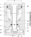
- FIG. 5 to FIG. 8 are views illustrating an example of the regulator in related art.
- One open end of a tubular path 2 formed through a main body part 1 is an inlet port 21 of high-pressure fluid and the other open end thereof is an outlet port 22 of pressure-reduced fluid.
- An inlet cover 23 to airtightly introduce high-pressure fluid and an outlet cover 24 to airtightly extract pressure-regulated fluid pressure of which is regulated are respectively arranged in the inlet port 21 and the outlet port 22.
- a valve seat 3 including a seat holding member 33 that is a bulkhead in which a cylindrical valve seated seat 31 is provided inside by fitting of an outer peripheral projected edge provided in a projected manner on an outer peripheral end surface thereof into a fitting recessed part and in which a through hole 32 in an axial direction of the path 2 is formed is arranged in an inner side of the inlet port 21 in the path 2.
- a pressure regulation chamber 4 is formed in a direction on a side of the outlet port 22 of the valve seated seat 31 in the path 2.
- a piston pressure regulating valve 7 including a pressure regulating valve body 5, which includes a leading end surface 51 that can be closely in contact with the valve seated seat 31 of the valve seat 3 and which includes a tubular communicating path 52 both ends of which are opened, and a piston unit 6 that is formed around an outer periphery on a side of the outlet port 22 in the path 2 of the pressure regulating valve body 5 and that has a diameter larger than that of the pressure regulating valve body 5 is arranged slidably in the axial direction of the path 2 between the pressure regulation chamber 4 and the outlet port 22 in the path 2.
- the piston unit 6 is biased in a circumference thereof in a direction of the outlet port 22 in the path 2 by a pressure regulating spring 8 that has a predetermined load and that is arranged in an atmosphere chamber 61 provided concentrically in parallel with the pressure regulation chamber 4.
- the pressure regulating spring 8 is inserted from the outlet port 22 before attachment of the outlet cover 24 and the piston pressure regulating valve 7 is subsequently inserted therefrom during assembly.
- the pressure regulating spring 8 is inserted from the outlet port 22 before attachment of the outlet cover 24 and the piston pressure regulating valve 7 is subsequently inserted therefrom during assembly.
- a seat diameter (ds) of each of the valve seated seat 31 and the pressure regulating valve body 5 is set to be smaller than a diameter (db) of a high-pressure fuel airtight seal 91 in an outer peripheral part of the pressure regulating valve body 5.
- the present invention is to solve the problem, that is, to reduce an individual difference between products due to a size tolerance of each of a valve seated seat holding member 33, a valve seated seat 31, a piston pressure regulating valve 7, and a main body part 1 affected by a load of a pressure regulating spring 8, or a load variation at a set point of the pressure regulating spring 8 and to provide a regulator without a function loss due to a damage, leakage failure, or the like of the valve seated seat 31.
- the present invention provides a regulator according to claim 1.
- the present invention it is possible to easily and securely set the pressure regulating spring in a designated load position by monitoring a spring load and performing fixation in a state, in which a designated load is reached, when the pressure regulating valve body inserted from the inlet port into the path and the piston unit inserted from the outlet port into the path are fit to each other in an intended axial direction position.
- a diameter of the valve seated seat is made to be the same with a diameter of a high-pressure fuel airtight seal inserted and fit between an inner peripheral surface of the path, which is arranged in such a manner as to face the valve seated seat, and an outer periphery of the pressure regulating valve body.
- the valve seated seat is provided slidably, in an axial direction of the path, in a recessed part formed in the valve seated seat holding member through a buffer formed from a high-polymer material having elasticity.
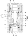
- FIG. 1 to FIG. 4 are sectional views of a preferred embodiment of the present invention.
- a whole configuration is substantially similar to that of related art illustrated in FIG. 5 to FIG. 8 , and a detailed description of these parts is omitted. Also, the same sign is assigned to a configuration part identical to that of the related art and described.
- a point different from the related art is that a cylindrical pressure regulating valve body 5 closely in contact with a valve seated seat 31 and a cylindrical piston unit 6 that is formed around an outer periphery thereof and that affects a pressure regulating spring 8 are formed separately in a piston pressure regulating valve 7.
- the pressure regulating valve body 5 and the piston unit 6 that is formed around the outer periphery thereof, the two being formed separately and forming the piston pressure regulating valve 7, are preferably formed in a close contact state in such a manner as to be insertable into a bore in which crimping is possible. It is preferably possible to temporarily join the two during assembly by inserting the pressure regulating valve body 5 separated from the piston unit 6 from an inlet port 21 into a path 2, inserting the piston unit 6 from an outlet port 22 into the path 2, and performing fitting to each other in a predetermined position in an axial direction in the path 2.
- a leading end, which is on a side in contact with the valve seated seat 31, of the cylindrical pressure regulating valve body 5 including a communicating path 52 inside has a tapered shape enlarged toward the leading end, a leading end on the opposite side has a shape of being joined to a coupling hole 62 in a center part of the piston unit 6, and an outer peripheral part is guided by a main body part 1 through a high-pressure fuel airtight seal 91. Also, an outer peripheral part of the piston unit 6 is guided by the main body part 1 through a seal member 92.
- a seat diameter (Ds) of a part of the pressure regulating valve body 5 which part is in contact with the valve seated seat 31 is equivalent to a seat diameter (Db) between the high-pressure fuel airtight seal 91 provided in the outer peripheral part of the pressure regulating valve body 5, and the pressure regulating valve body 5.
- a valve seated seat holding member 33 that forms a valve seat 3 is sandwiched in a step 11 inside the main body part 1 with a buffer 93 including an O-RING of a high-polymer material having high slidability and elasticity being between the inlet cover 23 to airtightly hold fuel and the valve seated seat holding member 33, and is semi-fixed only by elastic force of the buffer 93.
- the valve seated seat holding member 33 of the valve seat 3 has a structure of being slidable in a direction orthogonal to an axis.
- a substantially whole configuration and a pressure-reducing method of the above present embodiment are substantially similar to those of related art illustrated in FIG. 5 to FIG. 8 described above.
- the cylindrical pressure regulating valve body 5 that is closely in contact with the valve seated seat 31 and the cylindrical piston unit 6 that is formed around an outer periphery thereof and that affects the pressure regulating spring 8, the two being formed by the piston pressure regulating valve 7, are formed separately.
- the pressure regulating valve body 5 inserted from the inlet port 21 into the path 2 and the piston unit 6 inserted from the outlet port 22 into the path 2 are fit to each other in an intended axial direction position, and the pressure regulating valve body 5 and the piston unit 6 are fixed by welding or the like in a position, in which a load of the pressure regulating spring 8 becomes a designated load, and configure the piston pressure regulating valve 7.
- a load of the fuel inlet pressure (Pin) applied to the piston pressure regulating valve 7 can be canceled.
- a diameter of the valve seated seat 31 that forms the valve seat 3 is formed to be the same with a diameter of the high-pressure fuel airtight seal 91 inserted and fit between an inner peripheral surface of the path 2, which is arranged in such a manner as to face the valve seated seat 31, and an outer periphery of the pressure regulating valve body 5.
- an inner peripheral leading end, which is on a side of the valve seated seat 31, of the pressure regulating valve body 5 is formed in a tapered shape enlarged toward a leading end direction, and the valve seated seat 31 is provided slidably in the axial direction of the path 2 in a recessed part formed in the valve seated seat holding member 33 through an airtight member including, for example, an elastic material.
- valve seated seat holding member 33 that holds the valve seated seat 31 is slid and moved along with a contact part between the valve seated seat 31 and the pressure regulating valve body 5, the pressure regulating valve body 5 and the valve seated seat 31 are securely coaxial, and a contact surface between the valve seated seat 31 and the pressure regulating valve body 5 is uniformed, whereby an opening area of when a valve is opened also becomes uniform and it is possible to perform closing in such a manner that the valve seated seat 31 is closely in contact with the pressure regulating valve body 5 securely during closing.
- the inner peripheral leading end, which is on the side of the valve seated seat 31, of the pressure regulating valve body 5 is formed in a tapered shape enlarged toward the leading end direction, it becomes possible to automatically acquire effects such as valve leakage prevention, stabilization of a pressure-regulation performance, and control of a variation between products.
- the pressure regulating valve body 5 and the piston unit 6 it is possible to fix the pressure regulating valve body 5 and the piston unit 6 in a designated load position while measuring a load of the pressure regulating spring 8 during assembly, fixation being usually performed by welding or the like.
- fixation being usually performed by welding or the like.
- the pressure regulating valve body 5 and the piston unit 6 can be fit to each other by crimping, when pressure of used fluid is not that high, strength and airtightness can be secured in a temporally joined state in which fitting is performed in a press-fitted state, and a cost can be reduced by elimination of welding processing.
Landscapes
- Engineering & Computer Science (AREA)
- General Engineering & Computer Science (AREA)
- Physics & Mathematics (AREA)
- Mechanical Engineering (AREA)
- Automation & Control Theory (AREA)
- General Physics & Mathematics (AREA)
- Fluid Mechanics (AREA)
- Chemical & Material Sciences (AREA)
- Chemical Kinetics & Catalysis (AREA)
- General Chemical & Material Sciences (AREA)
- Oil, Petroleum & Natural Gas (AREA)
- Combustion & Propulsion (AREA)
- Safety Valves (AREA)
- Control Of Fluid Pressure (AREA)
- Fluid-Driven Valves (AREA)
Claims (4)
- Regler, bei dem ein offenes Ende in einem röhrenförmigen Weg (2), der durch ein Hauptkörperteil (1) gebildet ist, eine Einlassöffnung (21) für Hochdruckfluid ist und dessen anderes offenes Ende eine Auslassöffnung (22) für druckreduziertes Fluid ist, wobei eine Druckregulierungskammer (4) an einer Innenseite der Einlassöffnung (21) in dem Weg (2) über eine Ventilsitzanordnung (3) angeordnet ist, die ein Ventilsitz-Halteelement (33) enthält, das einen Ventilsitz (31) an einer Innenseite enthält und in dem ein Durchgangsloch (32) in einer axialen Richtung des Weges (2) ausgebildet ist, sowie ein Kolbendruckregelventil (7) mit einem Druckregelventilkörper (5), der eine vordere Endfläche (51) aufweist, die in engem Kontakt mit dem Ventilsitz (31) stehen kann, und der einen rohrförmigen Verbindungsweg (52) mit beiden geöffneten Enden aufweist, und eine Kolbeneinheit (6), die um einen äußeren Umfang des Druckregelventilkörpers (5) auf einer Seite der Auslassöffnung (22) in dem Weg (2) ausgebildet ist, in einer Auslassöffnungsrichtung in dem Weg (2) zwischen der Druckregulierungskammer (4) und der Auslassöffnung (22) in dem Weg (2) über eine Druckregelfeder (8) vorgespannt ist, die eine vorbestimmte Kraft aufweist und in der axialen Richtung des Weges (2) verschiebbar in einer Atmosphärenkammer (61) angeordnet ist, die koaxial parallel zu der Druckregulierungskammer (4) um die Kolbeneinheit (6) herum vorgesehen ist, und wobei Fluid, das durch Steuerung des Fluiddrucks in der Druckregulierungskammer (4) durch eine Änderung der Öffnungsbereiche des Ventilsitzes (31) und des Druckregelventilkörpers (5) aufgrund des Ausgleichs zwischen einer Druckkraft von von der Einlassöffnung (21) eingeleitetem Hochdruckfluid reguliert wird, in den Ventilsitz (31) und die dem Ventilsitz (31) zugewandt angeordnete Druckregulierungskammer (4) durch das in dem Ventilsitz-Halteelement (33) des Druckregelventilkörpers (5) ausgebildete Durchgangsloch (32) eingeleitet wird, durch den Druckregelventilkörper (5) hindurchgeht, in dem der Verbindungsweg (52) ausgebildet ist, und auf die mit dem Druckregelventilkörper (5) verbundene Kolbeneinheit (6) einwirkt, und wobei eine Kraft durch die Druckregelfeder (8), die auf die Kolbeneinheit (6) zu einer gegenüberliegenden Seite der Druckregulierungskammer (4) hin einwirkt, von der Auslassöffnung (22) abgeleitet wird,
wobei der Druckregelventilkörper (5), der in engem Kontakt mit dem Ventilsitz (31) steht, und die Kolbeneinheit (6), die um dessen äußeren Umfang herum ausgebildet ist und auf die Druckregelfeder (8) einwirkt, separat ausgebildet sind, wobei diese beiden das Kolben-Druckregelventil (7) bilden und der Druckregelventilkörper (5), der von der Einlassöffnung (21) in den Weg (2) eingesetzt ist, und die Kolbeneinheit (6), die von der Auslassöffnung (22) in den Weg (2) eingesetzt ist, in einer vorgesehenen axialen Richtungsposition aneinander angepasst und anschließend durch zumindest eines der Verfahren Presspassung und Verschweißen befestigt werden,
wobei ein innenliegendes, vorderes Umfangsende des Druckregelventilkörpers auf einer Seite des Ventilsitzes in einer sich verjüngenden Form ausgebildet ist, die sich in Richtung eines vorderen Endes erweitert. - Regler nach Anspruch 1, dadurch gekennzeichnet, dass dann, wenn der von der Einlassöffnung (21) in den Weg (2) eingesetzte Druckregelventilkörper (5) und die von der Auslassöffnung (22) in den Weg (2) eingesetzte Kolbeneinheit (6) in der vorgesehenen axialen Richtungsposition aneinander angepasst sind, eine Federkraft überwacht wird und die Befestigung in einem Zustand erfolgt, in dem eine vorgesehene Kraft erreicht ist.
- Regler nach Anspruch 1 oder 2, wobei ein Durchmesser des Ventilsitzes (31) mit einem Durchmesser einer luftdichten Hochdruck-Kraftstoff-Dichtung (91) übereinstimmt, die zwischen einer inneren Weg-Umfangsfläche, die dem Ventilsitz (31) zugewandt angeordnet ist, und dem Außenumfang des Druckregelventilkörpers (5) eingesetzt und eingepasst ist.
- Regler nach Anspruch 1, 2 oder 3, wobei der Ventilsitz (31) in axialer Richtung des Weges (2) verschiebbar in einem in dem Ventilsitz-Halteelement (33) ausgebildeten ausgesparten Teil mittels eines Puffers (93), der aus einem hochpolymeren, elastisch ausgebildeten Material gebildet ist, vorgesehen ist und wobei ein gleichmäßiger Kontakt zwischen dem Druckregelventilkörper (5) und dem Ventilsitz (31) ermöglicht ist.
Applications Claiming Priority (1)
| Application Number | Priority Date | Filing Date | Title |
|---|---|---|---|
| JP2017193078A JP6974834B2 (ja) | 2017-10-02 | 2017-10-02 | レギュレータ |
Publications (2)
| Publication Number | Publication Date |
|---|---|
| EP3462272A1 EP3462272A1 (de) | 2019-04-03 |
| EP3462272B1 true EP3462272B1 (de) | 2021-05-19 |
Family
ID=63683662
Family Applications (1)
| Application Number | Title | Priority Date | Filing Date |
|---|---|---|---|
| EP18196403.2A Active EP3462272B1 (de) | 2017-10-02 | 2018-09-24 | Regler |
Country Status (4)
| Country | Link |
|---|---|
| US (1) | US10871789B2 (de) |
| EP (1) | EP3462272B1 (de) |
| JP (1) | JP6974834B2 (de) |
| CN (1) | CN109595369B (de) |
Families Citing this family (13)
| Publication number | Priority date | Publication date | Assignee | Title |
|---|---|---|---|---|
| JP7197132B2 (ja) * | 2019-02-14 | 2022-12-27 | 株式会社ニッキ | レギュレータ |
| CN111946832B (zh) * | 2019-05-16 | 2025-11-21 | 芜湖美的厨卫电器制造有限公司 | 水阀和具有其的燃气设备 |
| US11585452B2 (en) * | 2019-12-03 | 2023-02-21 | Woodward, Inc. | Fuel nozzle with reduced flow tolerance |
| GB2594320A (en) * | 2020-04-24 | 2021-10-27 | Xiamen Synbop Tech Co Ltd | Small water heater |
| JP7557197B2 (ja) | 2020-10-19 | 2024-09-27 | 株式会社ニッキ | レギュレータ |
| CN112797209A (zh) * | 2021-01-28 | 2021-05-14 | 浙江元曜阀业有限公司 | 一种三级减压阀 |
| JP7662181B2 (ja) * | 2021-03-18 | 2025-04-15 | 株式会社ニッキ | レギュレータ |
| JP7575064B2 (ja) * | 2021-03-25 | 2024-10-29 | 株式会社ニッキ | レギュレータ |
| JP2023175563A (ja) | 2022-05-30 | 2023-12-12 | 株式会社ニッキ | 電子制御式レギュレータ |
| JP2024135017A (ja) | 2023-03-22 | 2024-10-04 | 株式会社ニッキ | レギュレータ |
| CN116447365A (zh) * | 2023-04-18 | 2023-07-18 | 国家开放大学 | 一种压力调节器及灌溉系统 |
| JP2025173237A (ja) | 2024-05-14 | 2025-11-27 | 株式会社ニッキ | エンジンのガス燃料供給装置 |
| JP2026046482A (ja) | 2024-09-02 | 2026-03-13 | 株式会社ニッキ | レギュレータ |
Family Cites Families (21)
| Publication number | Priority date | Publication date | Assignee | Title |
|---|---|---|---|---|
| US2888949A (en) * | 1957-04-25 | 1959-06-02 | Robertshaw Fulton Controls Co | Flow control device |
| US3435843A (en) * | 1966-01-05 | 1969-04-01 | Otis Eng Corp | Valves |
| US3890999A (en) * | 1972-12-15 | 1975-06-24 | Eugene D Moskow | Fluid pressure regulator |
| US4020863A (en) * | 1975-10-09 | 1977-05-03 | Robertshaw Controls Company | Fluid pressure regulator construction |
| JPS5552146Y2 (de) * | 1976-01-06 | 1980-12-03 | ||
| JPS5292436A (en) | 1976-01-30 | 1977-08-03 | Hitachi Ltd | Optical letter scanning unit |
| JP2767544B2 (ja) * | 1994-01-31 | 1998-06-18 | エヌテーシー工業株式会社 | 水道用定圧弁 |
| US5860447A (en) * | 1996-05-10 | 1999-01-19 | Chu; David | In line pressure regulator valve with passive pressure release |
| US6374853B1 (en) * | 2000-11-30 | 2002-04-23 | Lindsay Manufacturing Company | Combined pressure regulator and shut-off valve |
| ITSV20010001A1 (it) * | 2001-01-11 | 2002-07-11 | Scubapro Europ | Valvola riduttrice di pressione |
| US7191790B1 (en) * | 2003-07-04 | 2007-03-20 | Scott Technologies, Inc. | Quick connect pressure reducer/cylinder valve for self-contained breathing apparatus |
| JP2006292184A (ja) * | 2005-04-06 | 2006-10-26 | Tgk Co Ltd | 膨張装置 |
| US7401622B2 (en) * | 2006-06-09 | 2008-07-22 | Nelson Irrigation Corporation | Modular pressure regulator |
| US20090242043A1 (en) * | 2008-03-31 | 2009-10-01 | Gm Global Technology Operations, Inc. | Hydrogen supply pressure regulator |
| EP2166424B1 (de) * | 2008-09-19 | 2017-06-07 | Isomatic A/S | Flüssigkeitsregler |
| CN102494156B (zh) * | 2011-12-15 | 2013-04-10 | 重庆科特工业阀门有限公司 | 泄压指挥阀 |
| JP6218023B2 (ja) * | 2013-09-25 | 2017-10-25 | 株式会社テージーケー | 電磁弁 |
| US9434459B2 (en) * | 2014-03-13 | 2016-09-06 | Johnson Outdoors Inc. | Thermal insulating bushing for piston first stages |
| CN105715841A (zh) * | 2016-04-01 | 2016-06-29 | 成都科盛石油科技有限公司 | 一种气阀结构 |
| CN206145206U (zh) * | 2016-10-27 | 2017-05-03 | 泸州江阳超能燃气有限责任公司 | 一种减震型天然气减压器 |
| CN206093089U (zh) * | 2016-10-27 | 2017-04-12 | 泸州江阳超能燃气有限责任公司 | 一种用于压缩天然气减压的减压器 |
-
2017
- 2017-10-02 JP JP2017193078A patent/JP6974834B2/ja active Active
-
2018
- 2018-09-21 CN CN201811108211.1A patent/CN109595369B/zh active Active
- 2018-09-24 EP EP18196403.2A patent/EP3462272B1/de active Active
- 2018-10-01 US US16/149,115 patent/US10871789B2/en active Active
Also Published As
| Publication number | Publication date |
|---|---|
| US10871789B2 (en) | 2020-12-22 |
| US20190101942A1 (en) | 2019-04-04 |
| CN109595369A (zh) | 2019-04-09 |
| EP3462272A1 (de) | 2019-04-03 |
| JP2019067216A (ja) | 2019-04-25 |
| CN109595369B (zh) | 2022-03-22 |
| JP6974834B2 (ja) | 2021-12-01 |
Similar Documents
| Publication | Publication Date | Title |
|---|---|---|
| EP3462272B1 (de) | Regler | |
| US7686280B2 (en) | Removable valve seat member for diaphragm valve | |
| EP2307774B1 (de) | Überdruckventil | |
| US8590858B2 (en) | Anti-gradient cupped seat for pressure regulator | |
| EP2602525A1 (de) | Druckregelventil für gas | |
| JP2004101163A (ja) | 定流量膨張弁 | |
| JP2004502229A (ja) | ガス流調整システム | |
| EP3118500A1 (de) | Elektromagnetisches steuerventil | |
| EP3246607A1 (de) | In-line-absperrventile | |
| EP2689169B1 (de) | Haubenvorrichtung zur verwendung mit flüssigkeitsregulatoren | |
| US11137074B2 (en) | Regulator | |
| US5386848A (en) | Pneumatic check valve and method for making same | |
| US20040036044A1 (en) | Differential pressure control valve | |
| US7958768B2 (en) | System to control pressure in a test device | |
| US11739715B2 (en) | Regulator | |
| EP1522803B1 (de) | Konstantdifferential Druckventil | |
| US10216202B2 (en) | Pressure regulating valve | |
| JP4588656B2 (ja) | 電磁弁一体型膨張弁 | |
| CN211599686U (zh) | 氢压力控制阀 | |
| HK40069986A (en) | Regulator | |
| EP4446576A1 (de) | Druckregler | |
| JP3409671B2 (ja) | リリーフバルブの組付方法 | |
| JP3788975B2 (ja) | 遮断弁装置 | |
| US20100065565A1 (en) | Gradual release pressurizing valve for fluid storage tank breather and breather including same |
Legal Events
| Date | Code | Title | Description |
|---|---|---|---|
| PUAI | Public reference made under article 153(3) epc to a published international application that has entered the european phase |
Free format text: ORIGINAL CODE: 0009012 |
|
| STAA | Information on the status of an ep patent application or granted ep patent |
Free format text: STATUS: THE APPLICATION HAS BEEN PUBLISHED |
|
| AK | Designated contracting states |
Kind code of ref document: A1 Designated state(s): AL AT BE BG CH CY CZ DE DK EE ES FI FR GB GR HR HU IE IS IT LI LT LU LV MC MK MT NL NO PL PT RO RS SE SI SK SM TR |
|
| AX | Request for extension of the european patent |
Extension state: BA ME |
|
| STAA | Information on the status of an ep patent application or granted ep patent |
Free format text: STATUS: REQUEST FOR EXAMINATION WAS MADE |
|
| 17P | Request for examination filed |
Effective date: 20190920 |
|
| RBV | Designated contracting states (corrected) |
Designated state(s): AL AT BE BG CH CY CZ DE DK EE ES FI FR GB GR HR HU IE IS IT LI LT LU LV MC MK MT NL NO PL PT RO RS SE SI SK SM TR |
|
| GRAP | Despatch of communication of intention to grant a patent |
Free format text: ORIGINAL CODE: EPIDOSNIGR1 |
|
| STAA | Information on the status of an ep patent application or granted ep patent |
Free format text: STATUS: GRANT OF PATENT IS INTENDED |
|
| RIC1 | Information provided on ipc code assigned before grant |
Ipc: G05D 16/10 20060101AFI20201203BHEP Ipc: F02M 21/02 20060101ALI20201203BHEP |
|
| INTG | Intention to grant announced |
Effective date: 20201221 |
|
| GRAS | Grant fee paid |
Free format text: ORIGINAL CODE: EPIDOSNIGR3 |
|
| GRAA | (expected) grant |
Free format text: ORIGINAL CODE: 0009210 |
|
| STAA | Information on the status of an ep patent application or granted ep patent |
Free format text: STATUS: THE PATENT HAS BEEN GRANTED |
|
| AK | Designated contracting states |
Kind code of ref document: B1 Designated state(s): AL AT BE BG CH CY CZ DE DK EE ES FI FR GB GR HR HU IE IS IT LI LT LU LV MC MK MT NL NO PL PT RO RS SE SI SK SM TR |
|
| REG | Reference to a national code |
Ref country code: GB Ref legal event code: FG4D |
|
| REG | Reference to a national code |
Ref country code: CH Ref legal event code: EP |
|
| REG | Reference to a national code |
Ref country code: DE Ref legal event code: R096 Ref document number: 602018017202 Country of ref document: DE |
|
| REG | Reference to a national code |
Ref country code: AT Ref legal event code: REF Ref document number: 1394613 Country of ref document: AT Kind code of ref document: T Effective date: 20210615 |
|
| REG | Reference to a national code |
Ref country code: IE Ref legal event code: FG4D |
|
| REG | Reference to a national code |
Ref country code: LT Ref legal event code: MG9D |
|
| REG | Reference to a national code |
Ref country code: AT Ref legal event code: MK05 Ref document number: 1394613 Country of ref document: AT Kind code of ref document: T Effective date: 20210519 |
|
| REG | Reference to a national code |
Ref country code: NL Ref legal event code: MP Effective date: 20210519 |
|
| PG25 | Lapsed in a contracting state [announced via postgrant information from national office to epo] |
Ref country code: LT Free format text: LAPSE BECAUSE OF FAILURE TO SUBMIT A TRANSLATION OF THE DESCRIPTION OR TO PAY THE FEE WITHIN THE PRESCRIBED TIME-LIMIT Effective date: 20210519 Ref country code: HR Free format text: LAPSE BECAUSE OF FAILURE TO SUBMIT A TRANSLATION OF THE DESCRIPTION OR TO PAY THE FEE WITHIN THE PRESCRIBED TIME-LIMIT Effective date: 20210519 Ref country code: FI Free format text: LAPSE BECAUSE OF FAILURE TO SUBMIT A TRANSLATION OF THE DESCRIPTION OR TO PAY THE FEE WITHIN THE PRESCRIBED TIME-LIMIT Effective date: 20210519 Ref country code: BG Free format text: LAPSE BECAUSE OF FAILURE TO SUBMIT A TRANSLATION OF THE DESCRIPTION OR TO PAY THE FEE WITHIN THE PRESCRIBED TIME-LIMIT Effective date: 20210819 Ref country code: AT Free format text: LAPSE BECAUSE OF FAILURE TO SUBMIT A TRANSLATION OF THE DESCRIPTION OR TO PAY THE FEE WITHIN THE PRESCRIBED TIME-LIMIT Effective date: 20210519 |
|
| PG25 | Lapsed in a contracting state [announced via postgrant information from national office to epo] |
Ref country code: IS Free format text: LAPSE BECAUSE OF FAILURE TO SUBMIT A TRANSLATION OF THE DESCRIPTION OR TO PAY THE FEE WITHIN THE PRESCRIBED TIME-LIMIT Effective date: 20210919 Ref country code: GR Free format text: LAPSE BECAUSE OF FAILURE TO SUBMIT A TRANSLATION OF THE DESCRIPTION OR TO PAY THE FEE WITHIN THE PRESCRIBED TIME-LIMIT Effective date: 20210820 Ref country code: PL Free format text: LAPSE BECAUSE OF FAILURE TO SUBMIT A TRANSLATION OF THE DESCRIPTION OR TO PAY THE FEE WITHIN THE PRESCRIBED TIME-LIMIT Effective date: 20210519 Ref country code: LV Free format text: LAPSE BECAUSE OF FAILURE TO SUBMIT A TRANSLATION OF THE DESCRIPTION OR TO PAY THE FEE WITHIN THE PRESCRIBED TIME-LIMIT Effective date: 20210519 Ref country code: NO Free format text: LAPSE BECAUSE OF FAILURE TO SUBMIT A TRANSLATION OF THE DESCRIPTION OR TO PAY THE FEE WITHIN THE PRESCRIBED TIME-LIMIT Effective date: 20210819 Ref country code: PT Free format text: LAPSE BECAUSE OF FAILURE TO SUBMIT A TRANSLATION OF THE DESCRIPTION OR TO PAY THE FEE WITHIN THE PRESCRIBED TIME-LIMIT Effective date: 20210920 Ref country code: RS Free format text: LAPSE BECAUSE OF FAILURE TO SUBMIT A TRANSLATION OF THE DESCRIPTION OR TO PAY THE FEE WITHIN THE PRESCRIBED TIME-LIMIT Effective date: 20210519 Ref country code: SE Free format text: LAPSE BECAUSE OF FAILURE TO SUBMIT A TRANSLATION OF THE DESCRIPTION OR TO PAY THE FEE WITHIN THE PRESCRIBED TIME-LIMIT Effective date: 20210519 |
|
| PG25 | Lapsed in a contracting state [announced via postgrant information from national office to epo] |
Ref country code: NL Free format text: LAPSE BECAUSE OF FAILURE TO SUBMIT A TRANSLATION OF THE DESCRIPTION OR TO PAY THE FEE WITHIN THE PRESCRIBED TIME-LIMIT Effective date: 20210519 |
|
| PG25 | Lapsed in a contracting state [announced via postgrant information from national office to epo] |
Ref country code: DK Free format text: LAPSE BECAUSE OF FAILURE TO SUBMIT A TRANSLATION OF THE DESCRIPTION OR TO PAY THE FEE WITHIN THE PRESCRIBED TIME-LIMIT Effective date: 20210519 Ref country code: CZ Free format text: LAPSE BECAUSE OF FAILURE TO SUBMIT A TRANSLATION OF THE DESCRIPTION OR TO PAY THE FEE WITHIN THE PRESCRIBED TIME-LIMIT Effective date: 20210519 Ref country code: RO Free format text: LAPSE BECAUSE OF FAILURE TO SUBMIT A TRANSLATION OF THE DESCRIPTION OR TO PAY THE FEE WITHIN THE PRESCRIBED TIME-LIMIT Effective date: 20210519 Ref country code: SM Free format text: LAPSE BECAUSE OF FAILURE TO SUBMIT A TRANSLATION OF THE DESCRIPTION OR TO PAY THE FEE WITHIN THE PRESCRIBED TIME-LIMIT Effective date: 20210519 Ref country code: SK Free format text: LAPSE BECAUSE OF FAILURE TO SUBMIT A TRANSLATION OF THE DESCRIPTION OR TO PAY THE FEE WITHIN THE PRESCRIBED TIME-LIMIT Effective date: 20210519 Ref country code: ES Free format text: LAPSE BECAUSE OF FAILURE TO SUBMIT A TRANSLATION OF THE DESCRIPTION OR TO PAY THE FEE WITHIN THE PRESCRIBED TIME-LIMIT Effective date: 20210519 Ref country code: EE Free format text: LAPSE BECAUSE OF FAILURE TO SUBMIT A TRANSLATION OF THE DESCRIPTION OR TO PAY THE FEE WITHIN THE PRESCRIBED TIME-LIMIT Effective date: 20210519 |
|
| REG | Reference to a national code |
Ref country code: DE Ref legal event code: R097 Ref document number: 602018017202 Country of ref document: DE |
|
| PLBE | No opposition filed within time limit |
Free format text: ORIGINAL CODE: 0009261 |
|
| STAA | Information on the status of an ep patent application or granted ep patent |
Free format text: STATUS: NO OPPOSITION FILED WITHIN TIME LIMIT |
|
| REG | Reference to a national code |
Ref country code: DE Ref legal event code: R119 Ref document number: 602018017202 Country of ref document: DE |
|
| 26N | No opposition filed |
Effective date: 20220222 |
|
| REG | Reference to a national code |
Ref country code: CH Ref legal event code: PL |
|
| REG | Reference to a national code |
Ref country code: BE Ref legal event code: MM Effective date: 20210930 |
|
| PG25 | Lapsed in a contracting state [announced via postgrant information from national office to epo] |
Ref country code: IS Free format text: LAPSE BECAUSE OF FAILURE TO SUBMIT A TRANSLATION OF THE DESCRIPTION OR TO PAY THE FEE WITHIN THE PRESCRIBED TIME-LIMIT Effective date: 20210919 Ref country code: MC Free format text: LAPSE BECAUSE OF FAILURE TO SUBMIT A TRANSLATION OF THE DESCRIPTION OR TO PAY THE FEE WITHIN THE PRESCRIBED TIME-LIMIT Effective date: 20210519 Ref country code: AL Free format text: LAPSE BECAUSE OF FAILURE TO SUBMIT A TRANSLATION OF THE DESCRIPTION OR TO PAY THE FEE WITHIN THE PRESCRIBED TIME-LIMIT Effective date: 20210519 |
|
| PG25 | Lapsed in a contracting state [announced via postgrant information from national office to epo] |
Ref country code: LU Free format text: LAPSE BECAUSE OF NON-PAYMENT OF DUE FEES Effective date: 20210924 Ref country code: IE Free format text: LAPSE BECAUSE OF NON-PAYMENT OF DUE FEES Effective date: 20210924 Ref country code: FR Free format text: LAPSE BECAUSE OF NON-PAYMENT OF DUE FEES Effective date: 20210930 Ref country code: DE Free format text: LAPSE BECAUSE OF NON-PAYMENT OF DUE FEES Effective date: 20220401 Ref country code: BE Free format text: LAPSE BECAUSE OF NON-PAYMENT OF DUE FEES Effective date: 20210930 |
|
| PG25 | Lapsed in a contracting state [announced via postgrant information from national office to epo] |
Ref country code: LI Free format text: LAPSE BECAUSE OF NON-PAYMENT OF DUE FEES Effective date: 20210930 Ref country code: CH Free format text: LAPSE BECAUSE OF NON-PAYMENT OF DUE FEES Effective date: 20210930 |
|
| GBPC | Gb: european patent ceased through non-payment of renewal fee |
Effective date: 20220924 |
|
| P01 | Opt-out of the competence of the unified patent court (upc) registered |
Effective date: 20230428 |
|
| PG25 | Lapsed in a contracting state [announced via postgrant information from national office to epo] |
Ref country code: CY Free format text: LAPSE BECAUSE OF FAILURE TO SUBMIT A TRANSLATION OF THE DESCRIPTION OR TO PAY THE FEE WITHIN THE PRESCRIBED TIME-LIMIT Effective date: 20210519 |
|
| PG25 | Lapsed in a contracting state [announced via postgrant information from national office to epo] |
Ref country code: HU Free format text: LAPSE BECAUSE OF FAILURE TO SUBMIT A TRANSLATION OF THE DESCRIPTION OR TO PAY THE FEE WITHIN THE PRESCRIBED TIME-LIMIT; INVALID AB INITIO Effective date: 20180924 |
|
| PG25 | Lapsed in a contracting state [announced via postgrant information from national office to epo] |
Ref country code: GB Free format text: LAPSE BECAUSE OF NON-PAYMENT OF DUE FEES Effective date: 20220924 |
|
| PG25 | Lapsed in a contracting state [announced via postgrant information from national office to epo] |
Ref country code: MK Free format text: LAPSE BECAUSE OF FAILURE TO SUBMIT A TRANSLATION OF THE DESCRIPTION OR TO PAY THE FEE WITHIN THE PRESCRIBED TIME-LIMIT Effective date: 20210519 |
|
| PG25 | Lapsed in a contracting state [announced via postgrant information from national office to epo] |
Ref country code: TR Free format text: LAPSE BECAUSE OF FAILURE TO SUBMIT A TRANSLATION OF THE DESCRIPTION OR TO PAY THE FEE WITHIN THE PRESCRIBED TIME-LIMIT Effective date: 20210519 |
|
| PG25 | Lapsed in a contracting state [announced via postgrant information from national office to epo] |
Ref country code: MT Free format text: LAPSE BECAUSE OF FAILURE TO SUBMIT A TRANSLATION OF THE DESCRIPTION OR TO PAY THE FEE WITHIN THE PRESCRIBED TIME-LIMIT Effective date: 20210519 |
|
| PGFP | Annual fee paid to national office [announced via postgrant information from national office to epo] |
Ref country code: IT Payment date: 20250918 Year of fee payment: 8 |