EP3246607A1 - In-line-absperrventile - Google Patents
In-line-absperrventile Download PDFInfo
- Publication number
- EP3246607A1 EP3246607A1 EP17171948.7A EP17171948A EP3246607A1 EP 3246607 A1 EP3246607 A1 EP 3246607A1 EP 17171948 A EP17171948 A EP 17171948A EP 3246607 A1 EP3246607 A1 EP 3246607A1
- Authority
- EP
- European Patent Office
- Prior art keywords
- poppet
- servo
- port
- shutoff valve
- line shutoff
- Prior art date
- Legal status (The legal status is an assumption and is not a legal conclusion. Google has not performed a legal analysis and makes no representation as to the accuracy of the status listed.)
- Granted
Links
- 239000012530 fluid Substances 0.000 claims abstract description 120
- 238000004891 communication Methods 0.000 claims abstract description 30
- 230000008878 coupling Effects 0.000 claims abstract description 5
- 238000010168 coupling process Methods 0.000 claims abstract description 5
- 238000005859 coupling reaction Methods 0.000 claims abstract description 5
- 238000000034 method Methods 0.000 claims description 12
- 238000001816 cooling Methods 0.000 claims description 11
- 239000000463 material Substances 0.000 description 12
- 239000002826 coolant Substances 0.000 description 5
- 238000011144 upstream manufacturing Methods 0.000 description 3
- 238000009825 accumulation Methods 0.000 description 2
- 238000011161 development Methods 0.000 description 2
- 230000007613 environmental effect Effects 0.000 description 2
- 238000007789 sealing Methods 0.000 description 2
- 238000013459 approach Methods 0.000 description 1
- 238000007796 conventional method Methods 0.000 description 1
- 238000012986 modification Methods 0.000 description 1
- 230000004048 modification Effects 0.000 description 1
- 230000001105 regulatory effect Effects 0.000 description 1
- 238000011160 research Methods 0.000 description 1
Images


Classifications
-
- F—MECHANICAL ENGINEERING; LIGHTING; HEATING; WEAPONS; BLASTING
- F16—ENGINEERING ELEMENTS AND UNITS; GENERAL MEASURES FOR PRODUCING AND MAINTAINING EFFECTIVE FUNCTIONING OF MACHINES OR INSTALLATIONS; THERMAL INSULATION IN GENERAL
- F16K—VALVES; TAPS; COCKS; ACTUATING-FLOATS; DEVICES FOR VENTING OR AERATING
- F16K1/00—Lift valves or globe valves, i.e. cut-off apparatus with closure members having at least a component of their opening and closing motion perpendicular to the closing faces
- F16K1/12—Lift valves or globe valves, i.e. cut-off apparatus with closure members having at least a component of their opening and closing motion perpendicular to the closing faces with streamlined valve member around which the fluid flows when the valve is opened
- F16K1/126—Lift valves or globe valves, i.e. cut-off apparatus with closure members having at least a component of their opening and closing motion perpendicular to the closing faces with streamlined valve member around which the fluid flows when the valve is opened actuated by fluid
-
- F—MECHANICAL ENGINEERING; LIGHTING; HEATING; WEAPONS; BLASTING
- F01—MACHINES OR ENGINES IN GENERAL; ENGINE PLANTS IN GENERAL; STEAM ENGINES
- F01D—NON-POSITIVE DISPLACEMENT MACHINES OR ENGINES, e.g. STEAM TURBINES
- F01D17/00—Regulating or controlling by varying flow
- F01D17/10—Final actuators
- F01D17/12—Final actuators arranged in stator parts
- F01D17/14—Final actuators arranged in stator parts varying effective cross-sectional area of nozzles or guide conduits
- F01D17/141—Final actuators arranged in stator parts varying effective cross-sectional area of nozzles or guide conduits by means of shiftable members or valves obturating part of the flow path
- F01D17/145—Final actuators arranged in stator parts varying effective cross-sectional area of nozzles or guide conduits by means of shiftable members or valves obturating part of the flow path by means of valves, e.g. for steam turbines
-
- F—MECHANICAL ENGINEERING; LIGHTING; HEATING; WEAPONS; BLASTING
- F01—MACHINES OR ENGINES IN GENERAL; ENGINE PLANTS IN GENERAL; STEAM ENGINES
- F01D—NON-POSITIVE DISPLACEMENT MACHINES OR ENGINES, e.g. STEAM TURBINES
- F01D25/00—Component parts, details, or accessories, not provided for in, or of interest apart from, other groups
- F01D25/08—Cooling; Heating; Heat-insulation
- F01D25/12—Cooling
-
- F—MECHANICAL ENGINEERING; LIGHTING; HEATING; WEAPONS; BLASTING
- F02—COMBUSTION ENGINES; HOT-GAS OR COMBUSTION-PRODUCT ENGINE PLANTS
- F02C—GAS-TURBINE PLANTS; AIR INTAKES FOR JET-PROPULSION PLANTS; CONTROLLING FUEL SUPPLY IN AIR-BREATHING JET-PROPULSION PLANTS
- F02C6/00—Plural gas-turbine plants; Combinations of gas-turbine plants with other apparatus; Adaptations of gas-turbine plants for special use
- F02C6/04—Gas-turbine plants providing heated or pressurised working fluid for other apparatus, e.g. without mechanical power output
- F02C6/06—Gas-turbine plants providing heated or pressurised working fluid for other apparatus, e.g. without mechanical power output providing compressed gas
- F02C6/08—Gas-turbine plants providing heated or pressurised working fluid for other apparatus, e.g. without mechanical power output providing compressed gas the gas being bled from the gas-turbine compressor
-
- F—MECHANICAL ENGINEERING; LIGHTING; HEATING; WEAPONS; BLASTING
- F04—POSITIVE - DISPLACEMENT MACHINES FOR LIQUIDS; PUMPS FOR LIQUIDS OR ELASTIC FLUIDS
- F04D—NON-POSITIVE-DISPLACEMENT PUMPS
- F04D27/00—Control, e.g. regulation, of pumps, pumping installations or pumping systems specially adapted for elastic fluids
- F04D27/009—Control, e.g. regulation, of pumps, pumping installations or pumping systems specially adapted for elastic fluids by bleeding, by passing or recycling fluid
-
- F—MECHANICAL ENGINEERING; LIGHTING; HEATING; WEAPONS; BLASTING
- F16—ENGINEERING ELEMENTS AND UNITS; GENERAL MEASURES FOR PRODUCING AND MAINTAINING EFFECTIVE FUNCTIONING OF MACHINES OR INSTALLATIONS; THERMAL INSULATION IN GENERAL
- F16K—VALVES; TAPS; COCKS; ACTUATING-FLOATS; DEVICES FOR VENTING OR AERATING
- F16K1/00—Lift valves or globe valves, i.e. cut-off apparatus with closure members having at least a component of their opening and closing motion perpendicular to the closing faces
- F16K1/12—Lift valves or globe valves, i.e. cut-off apparatus with closure members having at least a component of their opening and closing motion perpendicular to the closing faces with streamlined valve member around which the fluid flows when the valve is opened
-
- F—MECHANICAL ENGINEERING; LIGHTING; HEATING; WEAPONS; BLASTING
- F16—ENGINEERING ELEMENTS AND UNITS; GENERAL MEASURES FOR PRODUCING AND MAINTAINING EFFECTIVE FUNCTIONING OF MACHINES OR INSTALLATIONS; THERMAL INSULATION IN GENERAL
- F16K—VALVES; TAPS; COCKS; ACTUATING-FLOATS; DEVICES FOR VENTING OR AERATING
- F16K17/00—Safety valves; Equalising valves, e.g. pressure relief valves
- F16K17/02—Safety valves; Equalising valves, e.g. pressure relief valves opening on surplus pressure on one side; closing on insufficient pressure on one side
-
- F—MECHANICAL ENGINEERING; LIGHTING; HEATING; WEAPONS; BLASTING
- F16—ENGINEERING ELEMENTS AND UNITS; GENERAL MEASURES FOR PRODUCING AND MAINTAINING EFFECTIVE FUNCTIONING OF MACHINES OR INSTALLATIONS; THERMAL INSULATION IN GENERAL
- F16K—VALVES; TAPS; COCKS; ACTUATING-FLOATS; DEVICES FOR VENTING OR AERATING
- F16K31/00—Actuating devices; Operating means; Releasing devices
- F16K31/02—Actuating devices; Operating means; Releasing devices electric; magnetic
- F16K31/04—Actuating devices; Operating means; Releasing devices electric; magnetic using a motor
-
- F—MECHANICAL ENGINEERING; LIGHTING; HEATING; WEAPONS; BLASTING
- F16—ENGINEERING ELEMENTS AND UNITS; GENERAL MEASURES FOR PRODUCING AND MAINTAINING EFFECTIVE FUNCTIONING OF MACHINES OR INSTALLATIONS; THERMAL INSULATION IN GENERAL
- F16K—VALVES; TAPS; COCKS; ACTUATING-FLOATS; DEVICES FOR VENTING OR AERATING
- F16K49/00—Means in or on valves for heating or cooling
- F16K49/005—Circulation means for a separate heat transfer fluid
- F16K49/007—Circulation means for a separate heat transfer fluid located within the obturating element
-
- F—MECHANICAL ENGINEERING; LIGHTING; HEATING; WEAPONS; BLASTING
- F01—MACHINES OR ENGINES IN GENERAL; ENGINE PLANTS IN GENERAL; STEAM ENGINES
- F01D—NON-POSITIVE DISPLACEMENT MACHINES OR ENGINES, e.g. STEAM TURBINES
- F01D17/00—Regulating or controlling by varying flow
- F01D17/10—Final actuators
- F01D17/105—Final actuators by passing part of the fluid
-
- F—MECHANICAL ENGINEERING; LIGHTING; HEATING; WEAPONS; BLASTING
- F05—INDEXING SCHEMES RELATING TO ENGINES OR PUMPS IN VARIOUS SUBCLASSES OF CLASSES F01-F04
- F05D—INDEXING SCHEME FOR ASPECTS RELATING TO NON-POSITIVE-DISPLACEMENT MACHINES OR ENGINES, GAS-TURBINES OR JET-PROPULSION PLANTS
- F05D2220/00—Application
- F05D2220/30—Application in turbines
- F05D2220/32—Application in turbines in gas turbines
-
- Y—GENERAL TAGGING OF NEW TECHNOLOGICAL DEVELOPMENTS; GENERAL TAGGING OF CROSS-SECTIONAL TECHNOLOGIES SPANNING OVER SEVERAL SECTIONS OF THE IPC; TECHNICAL SUBJECTS COVERED BY FORMER USPC CROSS-REFERENCE ART COLLECTIONS [XRACs] AND DIGESTS
- Y10—TECHNICAL SUBJECTS COVERED BY FORMER USPC
- Y10T—TECHNICAL SUBJECTS COVERED BY FORMER US CLASSIFICATION
- Y10T137/00—Fluid handling
- Y10T137/3367—Larner-Johnson type valves; i.e., telescoping internal valve in expanded flow line section
-
- Y—GENERAL TAGGING OF NEW TECHNOLOGICAL DEVELOPMENTS; GENERAL TAGGING OF CROSS-SECTIONAL TECHNOLOGIES SPANNING OVER SEVERAL SECTIONS OF THE IPC; TECHNICAL SUBJECTS COVERED BY FORMER USPC CROSS-REFERENCE ART COLLECTIONS [XRACs] AND DIGESTS
- Y10—TECHNICAL SUBJECTS COVERED BY FORMER USPC
- Y10T—TECHNICAL SUBJECTS COVERED BY FORMER US CLASSIFICATION
- Y10T137/00—Fluid handling
- Y10T137/6416—With heating or cooling of the system
- Y10T137/6579—Circulating fluid in heat exchange relationship
Definitions
- the present disclosure relates to pressure regulating devices, and more particularly to in-line shutoff valves for bleed passages in gas turbine engines.
- a variety of devices require a pressurized fluid in order to function properly.
- secondary aircraft systems such as environmental control systems and anti-ice systems often require an input supply of high temperature and pressure gas.
- Sources of pressurized gas for example, are present in the compressor of a gas turbine engine.
- the gas available from compressor may approach temperatures where materials forming flow-regulating structures begin to exhibit material properties changes.
- bleed flows may be sufficiently hot to reduce the strength of the material or increase the creep rate of the material for a given stress. Accordingly, it can be necessary to decrease the allowable stress budget for certain structures or to add material to the structure to accommodate the change in material properties associated with hot gas exposure.
- Heat conduction structures like fins can also be added to the structure to provide a conduction path for removal of heat from the structure.
- An in-line shutoff valve includes a valve body with an inlet chamber, an outlet chamber, and a poppet seat disposed between the inlet and outlet chambers.
- a poppet is movably disposed within the valve body and has an open and a closed position. The poppet seats against the poppet seat in the closed position, fluidly separating the inlet chamber from the outlet chamber. The poppet is unseated from the poppet seat in the open position, fluidly coupling the inlet chamber with the outlet chamber.
- a manifold with a servo port and a vent port is disposed within the valve body between the inlet and outlet chambers, the vent port being in fluid communication with the servo port to cool valve internal structures when the poppet is in the closed position.
- the poppet can have a poppet passage configured to selectively couple the servo port with the vent port according to position of the poppet.
- the poppet can extend about a longitudinal axis of the valve body.
- the poppet passage can extend radially through the poppet relative to the longitudinal axis of the valve body.
- a check valve can be seated in the poppet passage and arranged to fluidly separate the vent port from the servo port when pressure at the servo port exceed pressure at the vent port.
- a relief valve can be seated in the poppet passage and arranged to fluidly separate the vent port from the servo port when pressure differential between the vent port and the servo port exceeds a predetermined value.
- a guide tube can be fixed to the manifold.
- the poppet can be slideably received about the guide tube.
- the guide tube can define a guide tube channel and one or more guide tube orifices, the one or more guide tube orifices extending through the guide tube and fluidly coupling the guide tube channel with the servo port.
- the guide tube can extend about the longitudinal axis of the valve body.
- the guide tube can define an axial slot.
- the axial slot can be radially offset from the longitudinal axis of the valve body.
- the axial slot can extend axially along a portion of the length of the guide tube.
- the axial slot can be defined within an exterior surface of the guide tube. In the closed position, the poppet passage can axially overlap the axial slot of the guide tube. In the open position, the poppet passage can be axially offset from the axial slot of the guide tube.
- the poppet and the manifold can define between one another a vent chamber.
- the vent chamber can be in fluid communication with the servo port when the poppet is in the closed position.
- An end cap can be disposed between the poppet seat and the manifold.
- the end cap and the poppet can define between one another a servo chamber.
- the servo chamber can be in fluid communication with the vent port when the poppet is in the closed position.
- An outer seal ring can extend about the poppet between the poppet and the end cap.
- An inner seal ring can extend about the poppet between the poppet and the manifold.
- An in-line shutoff valve arrangement includes an in-line shutoff valve as describe above.
- the poppet has a poppet passage to couple the servo port with the vent port according to position of the poppet.
- a vent fluid source is fluidly coupled to the vent port to provide pressurized fluid to the vent port at a pressure that is greater than ambient pressure.
- a servo fluid source can be fluidly coupled to the servo port to provide pressurized fluid to the servo port with a pressure greater than that provided to the vent port by the vent fluid source.
- a method of cooling an in-line shutoff valve includes moving a poppet disposed within the in-line shutoff valve to a closed position, fluidly connecting the vent port with a servo port, and flowing fluid from the vent port to the servo port through an interior of the in-line shutoff valve.
- the poppet can be moved from the open position, the vent port fluidly separated from the servo port, and the poppet moved to the closed position.
- FIG. 1 a partial view of an exemplary embodiment of an in-line shutoff valve arrangement in accordance with the disclosure is shown in Fig. 1 and is designated generally by reference character 10.
- Other embodiments of in-line shutoff valve arrangements, in-line shutoff valves, and methods of cooling in-line shutoff valves in accordance with the disclosure, or aspects thereof, are provided in Figs. 2-6 , as will be described.
- the in-line shutoff valve arrangements, in-line shutoff valves, and methods of cooling in-line shutoff valves described herein can be in gas turbine engine compressor bleed arrangements, though the present disclosure is not limited to compressor bleed arrangements or to gas turbine engines in general.
- in-line shutoff valve arrangement 10 includes an in-line shutoff valve 100, a fluid source 12, a fluid destination 14, a servo fluid source 16, and a vent fluid source 18.
- Fluid source 12 can be a hot gas source, such as a compressor section of a gas turbine engine, and is in selective fluid communication with fluid destination 14 through in-line shutoff valve 100.
- Fluid destination 14 can be a hot gas destination, such as an environmental control system or a de-ice system for an aircraft, and selectively receives fluid from fluid source 12.
- Servo fluid source 16 includes a source of pressurized fluid configured to selectively flow pressurized servo fluid to in-line shutoff valve 100.
- Vent fluid source 18 includes a supply of pressurized coolant.
- vent fluid source 18 constantly applies a coolant fluid to in-line shutoff valve 100 at a temperature that is lower than that of fluid available from fluid source 12 and at a pressure that is greater than ambient pressure.
- servo fluid source 16 be configured to intermittently flow pressurized servo fluid to in-line shutoff valve 100 with a pressure that is greater than that of pressurized coolant fluid provided by vent fluid source 18, e.g., according to operational need to fluidly couple fluid source 12 with fluid destination 14.
- In-line shutoff valve 100 includes a valve body 102.
- Valve body 102 defines a longitudinal axis L and has within its interior an inlet chamber 108 and an outlet chamber 110.
- Inlet chamber 108 is disposed on a longitudinally opposite end of valve body 102 relative to outlet chamber 110.
- Fluid source 12 is in fluid communication with inlet chamber 108 of in-line shutoff valve 100.
- Fluid destination 14 is in fluid communication with outlet chamber 110 of in-line shutoff valve 100.
- Valve body 102 also has a servo port 112 and a vent port 114 defined on an exterior 116 of valve body 102.
- servo fluid source 16 is in selective fluid communication with servo port 112 and vent fluid source 18 is in continuous fluid communication with vent port 114.
- Servo fluid source 16 is configured and adapted to apply a servo pressure P S at servo port 112.
- Vent fluid source 18 is configured and adapted to apply a vent pressure P V at vent port 114.
- servo pressure P S is greater than vent pressure P V when present.
- vent pressure P V is substantially constant.
- Valve body 102 has within its interior a poppet 104, a poppet seat 106, an end cap 118, a manifold 120, a guide tube 122, and retaining pin 124.
- Poppet seat 106 is axially adjacent to outlet chamber 110.
- Manifold 120 is axially adjacent to inlet chamber 108 and defines servo port 112 and vent port 114.
- End cap 118 is disposed axially between poppet seat 106 and manifold 120.
- Guide tube 122 is disposed between end cap 118 and manifold 120 and extends axially along longitudinal axis L between end cap 118 and manifold 120.
- Guide tube 122 defines within its interior a guide tube passage 126 and has one or more guide tube orifices 128 extending radially outward relative to longitudinal axis L through a wall of guide tube 122.
- Retaining pin 124 extends axially along longitudinal axis L, within guide tube passage 126, and between manifold 120 and end cap 118 to fix end cap 118 to manifold 120.
- Poppet 104 is slideably seated over guide tube 122 and is movable between end cap 118 and manifold 120 along longitudinal axis L.
- poppet 104 and end cap 118 define between one another a servo chamber 130.
- Servo chamber 130 is in fluid communication with servo port 112 through the one or more guide tube orifices 128 and guide tube channel 126.
- An outer seal ring 132 is disposed about radially abutting surfaces of poppet 104 and end cap 118, thereby providing sealing between poppet 104 and end cap 118.
- poppet 104 and manifold 120 define between one another a vent chamber 134.
- Vent chamber 134 is in fluid communication vent port 114 and is in selective fluid communication with servo port 112 according to position of poppet 104, as will be further described below.
- An inner seal ring 136 being disposed between poppet 104 and manifold 120, thereby providing sealing between poppet 104 and manifold 120.
- Servo port 112 is in fluid communication with guide tube passage 126 through manifold 120.
- Guide tube passage 126 is in fluid communication with servo chamber 130 through the one or more guide tube orifice 128 defined on an end of guide tube 122 disposed within servo chamber 130.
- a servo fluid flow F S (shown in Fig. 2 ) fluid flows into servo chamber 130.
- Servo fluid flow F S exerts force on poppet 104 from within servo chamber 130 which, from a closed position I (shown in Fig. 1 ), unseats poppet 104 from poppet seat 106.
- Continuing accumulation of fluid within servo chamber 130 thereafter drives the unseated poppet 104 along longitudinal axis L such that poppet 104 reaches open position II (shown in Fig. 2 ), wherein poppet is displaced from poppet seat 106 and abuts manifold 120.
- Vent port 114 is in fluid communication with vent chamber 134 through manifold 120.
- a poppet passage 150 (illustrated schematically in Fig. 1 ) extends through poppet 104 between vent chamber 134 and servo chamber 130.
- Poppet passage 150 is configured and adapted to fluidly connect to selectively place vent chamber 134 in fluid communication with servo chamber 130 according to the position of poppet 104.
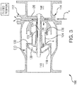
- poppet passage 150 fluidly couples vent chamber 134 with servo chamber 130 when poppet 104 is in closed position I (illustrated in Fig. 3 ). In this respect, when poppet 104 is in the closed position I, vent chamber 134 is in fluid communication with servo chamber 130 through poppet passage 150.
- vent chamber 134 Fluid communication between vent chamber 134 and servo chamber 130 allows fluid to flow from vent port 114 to servo port 112 when pressure applied at vent port 114 by vent fluid source 18 exceeds that of pressure at servo port 112.
- vent fluid is cooler than the internal structures of in-line shutoff valve 100, e.g., end cap 118, poppet 104, guide tube 122, retaining pin 124, and/or manifold 120, the fluid flow forms a conduction path for removing heat therefrom, enabling the removal of heat from interior structures within valve body 102.
- poppet passage 150 fluidly separates vent chamber 134 from servo chamber 130 when poppet 104 is not in closed position I, such as when poppet 104 is in open position II (shown in Fig. 2 ) or between closed position I and open position II.
- poppet 104 is shown in open position II. From closed position I (shown in Fig. 1 ), application servo pressure P V (shown in Fig. 1 ) at servo port 112 greater than vent pressure P V (shown in Fig. 1 ) applied at vent port 114 induces a causes servo fluid flow F S at servo port 112. Servo fluid flow F S traverses manifold 120 and guide tube channel 126, and enters servo chamber 130 through the one or more guide tube orifices 128. Entry of servo fluid flow F S into servo chamber 130 applies a drive force D to poppet 104.
- P V shown in Fig. 1
- vent pressure P V shown in Fig. 1
- Servo fluid flow F S traverses manifold 120 and guide tube channel 126, and enters servo chamber 130 through the one or more guide tube orifices 128. Entry of servo fluid flow F S into servo chamber 130 applies a drive force D to poppet 104.
- Drive force D is directed against poppet 104 and towards manifold 120, and unseats poppet 104 from poppet seat 106. Unseating poppet 104 from poppet seat 106 establishes annular flow area A, which places inlet chamber 108 in fluid communication with outlet chamber 110 such that fluid F flows from inlet chamber 108 to outlet chamber 110. Accumulation of servo fluid flow F S within servo chamber 130 displaces poppet 104 along longitudinal axis L, towards manifold 120, until poppet 104 reaches open position II, wherein poppet 104 abuts manifold 120.
- servo fluid flow F S When pressure at servo port 112 drops below pressure at vent port 114, servo fluid flow F S ceases. Cessation of servo fluid flow F S reduces (or removes entirely) drive force D from poppet 104. Removal of drive force D allows poppet 104 to translate along longitudinal axis L and toward end cap 118 relative to manifold 120, for example, from fluid flow F traversing the exterior surface of poppet 104 between inlet chamber 108 and outlet chamber 110 and/or through operation of a biasing element (not shown for reasons of clarity). Notably, no fluid communication occurs through poppet passage 150 when poppet 104 is in the open position. In certain embodiments, substantially no fluid communication occurs through poppet passage 150 when poppet 104 is unseated from poppet seat 106.
- poppet 104 is shown in closed position II.
- leakage of relatively hot fluid resident within inlet chamber 108 can enter various structures within valve body 102.
- small amounts of fluid from inlet chamber 108 may traverse outer seal ring 132 and enter servo chamber 130.
- Small amounts of fluid may also traverse inner seal ring 136 and enter vent chamber 134.
- the fluid can increase temperatures of internal structures within valve body 102, potentially raising the structure temperatures where materials forming internal structures exhibit material property changes. Such material property changes may influence the reliability of in-line shutoff valve 100.
- vent fluid flow F V in-line shutoff valve arrangement 10 (shown in Fig. 1 ) includes internal cooling.
- in-line shutoff valve arrangement 10 includes vent fluid source 18.
- poppet passage 150 fluidly couples vent chamber 134 with servo chamber 130. Fluidly coupling vent chamber 134 with servo chamber 130 places vent port 114 in fluid communication with servo port 112. As a consequence, when pressure at vent port 114 exceeds pressure at servo port 112, vent fluid flow F V enters manifold 120 from vent port 114. From manifold 120 vent fluid flow F V enters vent chamber 134 and flows into servo chamber 130 through poppet passage 150.
- vent fluid flow F V enters guide tube passage 126 through the one or more guide tube orifices 128, flows axially along the length of guide tube 122 to manifold 120, thereafter exiting valve body 102 through servo port 112. It is contemplated that vent fluid flow F V have a temperature that is lower than that of gas source 12 (shown in Fig. 1 ), vent fluid flow F V thereby transferring heat from internal structures within valve body 102, e.g., end cap 118, poppet 104, guide tube 122, retaining pin 124, and/or manifold 120. This allows for maintaining the temperature of one or more of the internal structures below a temperature at which the material properties of the material begin to change, potentially improving the reliability of in-line shutoff valve 100.
- poppet passage 150 extends radially through poppet 104 from vent chamber 134 and towards guide tube 122 (i.e. towards longitudinal axis L).
- Guide tube 122 defines an axial slot 154 that extends along an axial segment of the guide tube 122 and is in fluid communication with servo chamber 130.
- Axial slot 154 is bounded by an exterior surface of guide tube 122 and is disposed on a side of guide tube 122 that is radially opposite guide tube channel 126 relative to a wall of guide tube 122.
- poppet passage 150 when poppet 104 is in closed position I, poppet passage 150 axially overlaps axial slot 154 such that poppet passage 150 is in fluid communication with axial slot 154. Fluid communication of poppet passage 150 and axial slot 154 places vent chamber 134 in fluid communication with servo chamber 130, allowing vent fluid flow F V to traverse poppet passage 150 between vent chamber 134 and servo chamber 130.
- In-line shutoff valve 200 is similar to in-line shutoff valve 100 (shown in Fig. 1 ) and additionally includes an aperture 250 having a check valve 260 seated therein.
- Check valve 260 is configured and adapted to shut when pressure at servo port 212, and pressure within servo chamber 230, exceeds pressure at vent port 214, and pressure within vent chamber 234.
- check valve 260 enables servo chamber 230 to pressurize more rapidly upon application of pressurized servo fluid, e.g., servo fluid F S (shown in Fig.
- check valve 260 can enable the switching solenoid, e.g., servo fluid source 16 (shown in Fig. 1 ), to be relatively small and/or lightweight.
- In-line shutoff valve 300 is similar to in-line shutoff valve 100 (shown in Fig. 1 ), and additionally includes an aperture 350 having a relief valve seated therein.
- Relief valve 360 enables aperture 350 to fluidly connect vent chamber 334 with servo chamber 330 only at the highest inlet chamber temperatures and pressures, thereby limiting the use of internal cooling when the pressure difference between vent chamber 336 and ambient pressure in servo chamber 330 reaches a predetermined pressure value.
- the predetermined pressure value can correspond to valve inlet pressures and temperatures where cooling of internal components is advantageous.
- relief valve 360 enables servo chamber 330 to pressurize more rapidly upon application of pressurized servo fluid, e.g., servo fluid F S (shown in Fig. 2 ) than were servo chamber 330 and vent chamber 334 connected by an open poppet passage.
- pressurized servo fluid e.g., servo fluid F S (shown in Fig. 2 ) than were servo chamber 330 and vent chamber 334 connected by an open poppet passage.
- Relatively rapid pressurization of servo chamber 330 provided by relief valve 360 allows in-line shutoff valve 300 to be activated at a given upstream pressure with a relative low servo fluid pressure.
- a method of cooling an in-line shutoff valve includes receiving a coolant flow at a vent port, e.g., vent port 114 (shown in Fig. 1 ).
- the vent port is fluidly connected with a servo port, e.g., servo port 112 (shown in Fig. 1 ) by moving a poppet, e.g., poppet 104 (shown in Fig. 1 ) to a closed position.
- Coolant is flowed from the vent port to the servo port through the interior of the in-line shutoff valve to cool internal structure of the in-line shutoff valve.
- the method can include fluidly separating the vent port from the servo port by moving the poppet to an open position.
Landscapes
- Engineering & Computer Science (AREA)
- General Engineering & Computer Science (AREA)
- Mechanical Engineering (AREA)
- Physics & Mathematics (AREA)
- Fluid Mechanics (AREA)
- Thermal Sciences (AREA)
- Chemical & Material Sciences (AREA)
- Combustion & Propulsion (AREA)
- Life Sciences & Earth Sciences (AREA)
- Sustainable Development (AREA)
- Lift Valve (AREA)
- Details Of Valves (AREA)
Applications Claiming Priority (1)
| Application Number | Priority Date | Filing Date | Title |
|---|---|---|---|
| US15/159,268 US10001026B2 (en) | 2016-05-19 | 2016-05-19 | In-line shutoff valves |
Publications (2)
| Publication Number | Publication Date |
|---|---|
| EP3246607A1 true EP3246607A1 (de) | 2017-11-22 |
| EP3246607B1 EP3246607B1 (de) | 2019-01-23 |
Family
ID=58745105
Family Applications (1)
| Application Number | Title | Priority Date | Filing Date |
|---|---|---|---|
| EP17171948.7A Active EP3246607B1 (de) | 2016-05-19 | 2017-05-19 | In-line-absperrventile |
Country Status (2)
| Country | Link |
|---|---|
| US (1) | US10001026B2 (de) |
| EP (1) | EP3246607B1 (de) |
Cited By (1)
| Publication number | Priority date | Publication date | Assignee | Title |
|---|---|---|---|---|
| EP4191069A1 (de) * | 2021-10-22 | 2023-06-07 | Hamilton Sundstrand Corporation | Pneumatisches inline-ventil mit interner buchse |
Families Citing this family (8)
| Publication number | Priority date | Publication date | Assignee | Title |
|---|---|---|---|---|
| US10428971B1 (en) | 2018-03-06 | 2019-10-01 | Hamilton Sundstrand Corporation | Inline air valve nose cap for reduced contamination |
| US10513977B2 (en) | 2018-03-06 | 2019-12-24 | Hamilton Sundstrand Corporation | Adjustable snap action passive inline air valve |
| US10473225B2 (en) * | 2018-03-29 | 2019-11-12 | Hamilton Sundstrand Corporation | Passive valve |
| US11486313B2 (en) | 2019-06-14 | 2022-11-01 | Hamilton Sundstrand Corporation | Linear electric air valve |
| US10824172B1 (en) * | 2019-06-20 | 2020-11-03 | Hamilton Sunstrand Corporation | Pneumatic controllers, pneumatically controlled inline valves, and methods of actuating inline valves |
| US10830372B1 (en) * | 2019-06-20 | 2020-11-10 | Hamilton Sunstrand Corporation | Pneumatic controllers, pneumatically controlled inline valves, and methods of cooling pneumatic controllers |
| US10823087B1 (en) * | 2019-06-20 | 2020-11-03 | Hamilton Sunstrand Corporation | Inline valves, gas turbine engines with inline bleed valves, and methods controlling flow through inline valves |
| US10823308B1 (en) * | 2019-06-20 | 2020-11-03 | Hamilton Sunstrand Corporation | Controllers for inline valves, inline valves, and methods of controlling flow through inline valves |
Citations (6)
| Publication number | Priority date | Publication date | Assignee | Title |
|---|---|---|---|---|
| DE55632C (de) * | C. WIGAND in Hannover | Hahn mit Kühl- oder Heizleitung | ||
| GB843317A (en) * | 1957-05-22 | 1960-08-04 | Westinghouse Electric Corp | Improvements in or relating to fluid flow valve mechanisms |
| US3540464A (en) * | 1968-03-04 | 1970-11-17 | Avco Corp | Flow control valves |
| EP0066795A1 (de) * | 1981-06-01 | 1982-12-15 | Alsthom | Schnell schliessendes Ventil für komprimierbares Fluidum |
| FR2871212A1 (fr) * | 2004-06-03 | 2005-12-09 | Mp 98 Sarl | Dispositifs de fermeture et d'etancheite par tube a moyen immerge et profil d'ecoulement optimise |
| EP1635097A1 (de) * | 2004-09-08 | 2006-03-15 | Kabushiki Kaisha Toshiba | Hochtemperaturdampfventil und Dampfturbinenanlage |
Family Cites Families (10)
| Publication number | Priority date | Publication date | Assignee | Title |
|---|---|---|---|---|
| US1070693A (en) * | 1912-12-18 | 1913-08-19 | Paul L Keiser | Valve for hot-blast furnaces. |
| US2204724A (en) * | 1938-07-22 | 1940-06-18 | Cope Harold | Valve seat |
| US2446196A (en) * | 1945-03-20 | 1948-08-03 | Sitney Massey | Double seal valve |
| US2575875A (en) * | 1948-01-20 | 1951-11-20 | United States Steel Corp | High-temperature gas valve |
| US2994338A (en) * | 1957-05-22 | 1961-08-01 | Westinghouse Electric Corp | Fluid control apparatus |
| US3259143A (en) * | 1963-11-06 | 1966-07-05 | Koppers Co Inc | Cooled valve for high temperature gases |
| JPS508549B1 (de) * | 1970-05-27 | 1975-04-04 | ||
| BE795182A (fr) * | 1972-02-24 | 1973-05-29 | Thyssen Niederrhein Ag | Obturateur a clapet pour agencement de collecte d'eponge de fer |
| US4169488A (en) * | 1977-11-23 | 1979-10-02 | Caterpillar Tractor Co. | Cooled engine valve |
| US9151130B2 (en) * | 2012-02-02 | 2015-10-06 | Cameron International Corporation | System for controlling temperature of subsea equipment |
-
2016
- 2016-05-19 US US15/159,268 patent/US10001026B2/en active Active
-
2017
- 2017-05-19 EP EP17171948.7A patent/EP3246607B1/de active Active
Patent Citations (6)
| Publication number | Priority date | Publication date | Assignee | Title |
|---|---|---|---|---|
| DE55632C (de) * | C. WIGAND in Hannover | Hahn mit Kühl- oder Heizleitung | ||
| GB843317A (en) * | 1957-05-22 | 1960-08-04 | Westinghouse Electric Corp | Improvements in or relating to fluid flow valve mechanisms |
| US3540464A (en) * | 1968-03-04 | 1970-11-17 | Avco Corp | Flow control valves |
| EP0066795A1 (de) * | 1981-06-01 | 1982-12-15 | Alsthom | Schnell schliessendes Ventil für komprimierbares Fluidum |
| FR2871212A1 (fr) * | 2004-06-03 | 2005-12-09 | Mp 98 Sarl | Dispositifs de fermeture et d'etancheite par tube a moyen immerge et profil d'ecoulement optimise |
| EP1635097A1 (de) * | 2004-09-08 | 2006-03-15 | Kabushiki Kaisha Toshiba | Hochtemperaturdampfventil und Dampfturbinenanlage |
Cited By (2)
| Publication number | Priority date | Publication date | Assignee | Title |
|---|---|---|---|---|
| EP4191069A1 (de) * | 2021-10-22 | 2023-06-07 | Hamilton Sundstrand Corporation | Pneumatisches inline-ventil mit interner buchse |
| US11982358B2 (en) | 2021-10-22 | 2024-05-14 | Hamilton Sundstrand Corporation | Inline pneumatic valve with internal bushing |
Also Published As
| Publication number | Publication date |
|---|---|
| EP3246607B1 (de) | 2019-01-23 |
| US10001026B2 (en) | 2018-06-19 |
| US20170342853A1 (en) | 2017-11-30 |
Similar Documents
| Publication | Publication Date | Title |
|---|---|---|
| EP3246607B1 (de) | In-line-absperrventile | |
| EP3056739A1 (de) | Entlüftungsventil des hülsentyps, betätigt durch zwei steuerdrücke, die auf einem kolben wirken | |
| EP3225799A1 (de) | Pilotgesteuertes kolbenölkühlungsstrahlsteuerventil | |
| CA1049374A (en) | Thermally responsive by-pass valve device providing maximum flow area | |
| US9822900B2 (en) | Pneumatic mixing valve | |
| US9404513B2 (en) | Servo valve | |
| US9218005B2 (en) | Apparatus and method for reducing actuator thrust requirements in a control valve | |
| US10865800B2 (en) | Bleed valve with regulated opening | |
| EP3112690A1 (de) | Pneumatisch betätigtes hdv abblasventil, das von einem magnetventil gesteuert wird, das wiederum in seiner schliessstellung von einem flussbegrenzenden ventil unterstützt wird | |
| US20180112630A1 (en) | Pressure regulator | |
| US20130312843A1 (en) | Pressure and flow altitude compensated shutoff valve | |
| US10830365B2 (en) | Bi-directional inline check valve | |
| US11346356B2 (en) | Passive bleed valves with adjustable pressure threshold | |
| US4418716A (en) | Two-way flow valve | |
| EP3754231B1 (de) | Pneumatische steuerungen, pneumatisch gesteuerte inline-ventile und verfahren zum kühlen von pneumatischen steuerungen | |
| US11053949B2 (en) | Passively controlled inline bleed valves | |
| US11421594B2 (en) | Pressure relief valve | |
| US20160131042A1 (en) | Systems and methods for controlling fuel path availability for an aircraft | |
| US10268213B1 (en) | Check valve with pilot tube pressure sensing | |
| US20200025301A1 (en) | Damping mechanism for valves | |
| KR20150099108A (ko) | 온도 감응형 릴리프 밸브 및 이를 포함하는 오일 냉각 장치 |
Legal Events
| Date | Code | Title | Description |
|---|---|---|---|
| PUAI | Public reference made under article 153(3) epc to a published international application that has entered the european phase |
Free format text: ORIGINAL CODE: 0009012 |
|
| STAA | Information on the status of an ep patent application or granted ep patent |
Free format text: STATUS: THE APPLICATION HAS BEEN PUBLISHED |
|
| AK | Designated contracting states |
Kind code of ref document: A1 Designated state(s): AL AT BE BG CH CY CZ DE DK EE ES FI FR GB GR HR HU IE IS IT LI LT LU LV MC MK MT NL NO PL PT RO RS SE SI SK SM TR |
|
| AX | Request for extension of the european patent |
Extension state: BA ME |
|
| STAA | Information on the status of an ep patent application or granted ep patent |
Free format text: STATUS: REQUEST FOR EXAMINATION WAS MADE |
|
| 17P | Request for examination filed |
Effective date: 20180518 |
|
| RBV | Designated contracting states (corrected) |
Designated state(s): AL AT BE BG CH CY CZ DE DK EE ES FI FR GB GR HR HU IE IS IT LI LT LU LV MC MK MT NL NO PL PT RO RS SE SI SK SM TR |
|
| GRAP | Despatch of communication of intention to grant a patent |
Free format text: ORIGINAL CODE: EPIDOSNIGR1 |
|
| STAA | Information on the status of an ep patent application or granted ep patent |
Free format text: STATUS: GRANT OF PATENT IS INTENDED |
|
| INTG | Intention to grant announced |
Effective date: 20180711 |
|
| GRAJ | Information related to disapproval of communication of intention to grant by the applicant or resumption of examination proceedings by the epo deleted |
Free format text: ORIGINAL CODE: EPIDOSDIGR1 |
|
| STAA | Information on the status of an ep patent application or granted ep patent |
Free format text: STATUS: REQUEST FOR EXAMINATION WAS MADE |
|
| GRAR | Information related to intention to grant a patent recorded |
Free format text: ORIGINAL CODE: EPIDOSNIGR71 |
|
| GRAS | Grant fee paid |
Free format text: ORIGINAL CODE: EPIDOSNIGR3 |
|
| STAA | Information on the status of an ep patent application or granted ep patent |
Free format text: STATUS: GRANT OF PATENT IS INTENDED |
|
| GRAA | (expected) grant |
Free format text: ORIGINAL CODE: 0009210 |
|
| STAA | Information on the status of an ep patent application or granted ep patent |
Free format text: STATUS: THE PATENT HAS BEEN GRANTED |
|
| INTC | Intention to grant announced (deleted) | ||
| INTG | Intention to grant announced |
Effective date: 20181207 |
|
| AK | Designated contracting states |
Kind code of ref document: B1 Designated state(s): AL AT BE BG CH CY CZ DE DK EE ES FI FR GB GR HR HU IE IS IT LI LT LU LV MC MK MT NL NO PL PT RO RS SE SI SK SM TR |
|
| REG | Reference to a national code |
Ref country code: GB Ref legal event code: FG4D |
|
| REG | Reference to a national code |
Ref country code: CH Ref legal event code: EP |
|
| REG | Reference to a national code |
Ref country code: AT Ref legal event code: REF Ref document number: 1091718 Country of ref document: AT Kind code of ref document: T Effective date: 20190215 |
|
| REG | Reference to a national code |
Ref country code: IE Ref legal event code: FG4D |
|
| REG | Reference to a national code |
Ref country code: DE Ref legal event code: R096 Ref document number: 602017001872 Country of ref document: DE |
|
| REG | Reference to a national code |
Ref country code: NL Ref legal event code: MP Effective date: 20190123 |
|
| PG25 | Lapsed in a contracting state [announced via postgrant information from national office to epo] |
Ref country code: NL Free format text: LAPSE BECAUSE OF FAILURE TO SUBMIT A TRANSLATION OF THE DESCRIPTION OR TO PAY THE FEE WITHIN THE PRESCRIBED TIME-LIMIT Effective date: 20190123 |
|
| PG25 | Lapsed in a contracting state [announced via postgrant information from national office to epo] |
Ref country code: PT Free format text: LAPSE BECAUSE OF FAILURE TO SUBMIT A TRANSLATION OF THE DESCRIPTION OR TO PAY THE FEE WITHIN THE PRESCRIBED TIME-LIMIT Effective date: 20190523 Ref country code: ES Free format text: LAPSE BECAUSE OF FAILURE TO SUBMIT A TRANSLATION OF THE DESCRIPTION OR TO PAY THE FEE WITHIN THE PRESCRIBED TIME-LIMIT Effective date: 20190123 Ref country code: PL Free format text: LAPSE BECAUSE OF FAILURE TO SUBMIT A TRANSLATION OF THE DESCRIPTION OR TO PAY THE FEE WITHIN THE PRESCRIBED TIME-LIMIT Effective date: 20190123 Ref country code: SE Free format text: LAPSE BECAUSE OF FAILURE TO SUBMIT A TRANSLATION OF THE DESCRIPTION OR TO PAY THE FEE WITHIN THE PRESCRIBED TIME-LIMIT Effective date: 20190123 Ref country code: NO Free format text: LAPSE BECAUSE OF FAILURE TO SUBMIT A TRANSLATION OF THE DESCRIPTION OR TO PAY THE FEE WITHIN THE PRESCRIBED TIME-LIMIT Effective date: 20190423 Ref country code: FI Free format text: LAPSE BECAUSE OF FAILURE TO SUBMIT A TRANSLATION OF THE DESCRIPTION OR TO PAY THE FEE WITHIN THE PRESCRIBED TIME-LIMIT Effective date: 20190123 Ref country code: LT Free format text: LAPSE BECAUSE OF FAILURE TO SUBMIT A TRANSLATION OF THE DESCRIPTION OR TO PAY THE FEE WITHIN THE PRESCRIBED TIME-LIMIT Effective date: 20190123 |
|
| REG | Reference to a national code |
Ref country code: AT Ref legal event code: MK05 Ref document number: 1091718 Country of ref document: AT Kind code of ref document: T Effective date: 20190123 |
|
| PG25 | Lapsed in a contracting state [announced via postgrant information from national office to epo] |
Ref country code: BG Free format text: LAPSE BECAUSE OF FAILURE TO SUBMIT A TRANSLATION OF THE DESCRIPTION OR TO PAY THE FEE WITHIN THE PRESCRIBED TIME-LIMIT Effective date: 20190423 Ref country code: GR Free format text: LAPSE BECAUSE OF FAILURE TO SUBMIT A TRANSLATION OF THE DESCRIPTION OR TO PAY THE FEE WITHIN THE PRESCRIBED TIME-LIMIT Effective date: 20190424 Ref country code: HR Free format text: LAPSE BECAUSE OF FAILURE TO SUBMIT A TRANSLATION OF THE DESCRIPTION OR TO PAY THE FEE WITHIN THE PRESCRIBED TIME-LIMIT Effective date: 20190123 Ref country code: RS Free format text: LAPSE BECAUSE OF FAILURE TO SUBMIT A TRANSLATION OF THE DESCRIPTION OR TO PAY THE FEE WITHIN THE PRESCRIBED TIME-LIMIT Effective date: 20190123 Ref country code: IS Free format text: LAPSE BECAUSE OF FAILURE TO SUBMIT A TRANSLATION OF THE DESCRIPTION OR TO PAY THE FEE WITHIN THE PRESCRIBED TIME-LIMIT Effective date: 20190523 Ref country code: LV Free format text: LAPSE BECAUSE OF FAILURE TO SUBMIT A TRANSLATION OF THE DESCRIPTION OR TO PAY THE FEE WITHIN THE PRESCRIBED TIME-LIMIT Effective date: 20190123 |
|
| REG | Reference to a national code |
Ref country code: DE Ref legal event code: R097 Ref document number: 602017001872 Country of ref document: DE |
|
| PG25 | Lapsed in a contracting state [announced via postgrant information from national office to epo] |
Ref country code: IT Free format text: LAPSE BECAUSE OF FAILURE TO SUBMIT A TRANSLATION OF THE DESCRIPTION OR TO PAY THE FEE WITHIN THE PRESCRIBED TIME-LIMIT Effective date: 20190123 Ref country code: CZ Free format text: LAPSE BECAUSE OF FAILURE TO SUBMIT A TRANSLATION OF THE DESCRIPTION OR TO PAY THE FEE WITHIN THE PRESCRIBED TIME-LIMIT Effective date: 20190123 Ref country code: RO Free format text: LAPSE BECAUSE OF FAILURE TO SUBMIT A TRANSLATION OF THE DESCRIPTION OR TO PAY THE FEE WITHIN THE PRESCRIBED TIME-LIMIT Effective date: 20190123 Ref country code: SK Free format text: LAPSE BECAUSE OF FAILURE TO SUBMIT A TRANSLATION OF THE DESCRIPTION OR TO PAY THE FEE WITHIN THE PRESCRIBED TIME-LIMIT Effective date: 20190123 Ref country code: AL Free format text: LAPSE BECAUSE OF FAILURE TO SUBMIT A TRANSLATION OF THE DESCRIPTION OR TO PAY THE FEE WITHIN THE PRESCRIBED TIME-LIMIT Effective date: 20190123 Ref country code: EE Free format text: LAPSE BECAUSE OF FAILURE TO SUBMIT A TRANSLATION OF THE DESCRIPTION OR TO PAY THE FEE WITHIN THE PRESCRIBED TIME-LIMIT Effective date: 20190123 Ref country code: DK Free format text: LAPSE BECAUSE OF FAILURE TO SUBMIT A TRANSLATION OF THE DESCRIPTION OR TO PAY THE FEE WITHIN THE PRESCRIBED TIME-LIMIT Effective date: 20190123 |
|
| PG25 | Lapsed in a contracting state [announced via postgrant information from national office to epo] |
Ref country code: SM Free format text: LAPSE BECAUSE OF FAILURE TO SUBMIT A TRANSLATION OF THE DESCRIPTION OR TO PAY THE FEE WITHIN THE PRESCRIBED TIME-LIMIT Effective date: 20190123 |
|
| PLBE | No opposition filed within time limit |
Free format text: ORIGINAL CODE: 0009261 |
|
| STAA | Information on the status of an ep patent application or granted ep patent |
Free format text: STATUS: NO OPPOSITION FILED WITHIN TIME LIMIT |
|
| PG25 | Lapsed in a contracting state [announced via postgrant information from national office to epo] |
Ref country code: AT Free format text: LAPSE BECAUSE OF FAILURE TO SUBMIT A TRANSLATION OF THE DESCRIPTION OR TO PAY THE FEE WITHIN THE PRESCRIBED TIME-LIMIT Effective date: 20190123 |
|
| 26N | No opposition filed |
Effective date: 20191024 |
|
| PG25 | Lapsed in a contracting state [announced via postgrant information from national office to epo] |
Ref country code: MC Free format text: LAPSE BECAUSE OF FAILURE TO SUBMIT A TRANSLATION OF THE DESCRIPTION OR TO PAY THE FEE WITHIN THE PRESCRIBED TIME-LIMIT Effective date: 20190123 |
|
| REG | Reference to a national code |
Ref country code: BE Ref legal event code: MM Effective date: 20190531 |
|
| PG25 | Lapsed in a contracting state [announced via postgrant information from national office to epo] |
Ref country code: SI Free format text: LAPSE BECAUSE OF FAILURE TO SUBMIT A TRANSLATION OF THE DESCRIPTION OR TO PAY THE FEE WITHIN THE PRESCRIBED TIME-LIMIT Effective date: 20190123 Ref country code: LU Free format text: LAPSE BECAUSE OF NON-PAYMENT OF DUE FEES Effective date: 20190519 |
|
| PG25 | Lapsed in a contracting state [announced via postgrant information from national office to epo] |
Ref country code: TR Free format text: LAPSE BECAUSE OF FAILURE TO SUBMIT A TRANSLATION OF THE DESCRIPTION OR TO PAY THE FEE WITHIN THE PRESCRIBED TIME-LIMIT Effective date: 20190123 |
|
| PG25 | Lapsed in a contracting state [announced via postgrant information from national office to epo] |
Ref country code: IE Free format text: LAPSE BECAUSE OF NON-PAYMENT OF DUE FEES Effective date: 20190519 |
|
| PG25 | Lapsed in a contracting state [announced via postgrant information from national office to epo] |
Ref country code: BE Free format text: LAPSE BECAUSE OF NON-PAYMENT OF DUE FEES Effective date: 20190531 |
|
| PG25 | Lapsed in a contracting state [announced via postgrant information from national office to epo] |
Ref country code: CH Free format text: LAPSE BECAUSE OF NON-PAYMENT OF DUE FEES Effective date: 20200531 Ref country code: LI Free format text: LAPSE BECAUSE OF NON-PAYMENT OF DUE FEES Effective date: 20200531 |
|
| PG25 | Lapsed in a contracting state [announced via postgrant information from national office to epo] |
Ref country code: CY Free format text: LAPSE BECAUSE OF FAILURE TO SUBMIT A TRANSLATION OF THE DESCRIPTION OR TO PAY THE FEE WITHIN THE PRESCRIBED TIME-LIMIT Effective date: 20190123 |
|
| PG25 | Lapsed in a contracting state [announced via postgrant information from national office to epo] |
Ref country code: MT Free format text: LAPSE BECAUSE OF FAILURE TO SUBMIT A TRANSLATION OF THE DESCRIPTION OR TO PAY THE FEE WITHIN THE PRESCRIBED TIME-LIMIT Effective date: 20190123 Ref country code: HU Free format text: LAPSE BECAUSE OF FAILURE TO SUBMIT A TRANSLATION OF THE DESCRIPTION OR TO PAY THE FEE WITHIN THE PRESCRIBED TIME-LIMIT; INVALID AB INITIO Effective date: 20170519 |
|
| PG25 | Lapsed in a contracting state [announced via postgrant information from national office to epo] |
Ref country code: MK Free format text: LAPSE BECAUSE OF FAILURE TO SUBMIT A TRANSLATION OF THE DESCRIPTION OR TO PAY THE FEE WITHIN THE PRESCRIBED TIME-LIMIT Effective date: 20190123 |
|
| P01 | Opt-out of the competence of the unified patent court (upc) registered |
Effective date: 20230522 |
|
| PGFP | Annual fee paid to national office [announced via postgrant information from national office to epo] |
Ref country code: FR Payment date: 20230420 Year of fee payment: 7 Ref country code: DE Payment date: 20230419 Year of fee payment: 7 |
|
| PGFP | Annual fee paid to national office [announced via postgrant information from national office to epo] |
Ref country code: GB Payment date: 20230420 Year of fee payment: 7 |