EP4191069A1 - Pneumatisches inline-ventil mit interner buchse - Google Patents
Pneumatisches inline-ventil mit interner buchse Download PDFInfo
- Publication number
- EP4191069A1 EP4191069A1 EP22202790.6A EP22202790A EP4191069A1 EP 4191069 A1 EP4191069 A1 EP 4191069A1 EP 22202790 A EP22202790 A EP 22202790A EP 4191069 A1 EP4191069 A1 EP 4191069A1
- Authority
- EP
- European Patent Office
- Prior art keywords
- piston
- valve
- bushing
- housing
- inner sliding
- Prior art date
- Legal status (The legal status is an assumption and is not a legal conclusion. Google has not performed a legal analysis and makes no representation as to the accuracy of the status listed.)
- Pending
Links
Images


Classifications
-
- F—MECHANICAL ENGINEERING; LIGHTING; HEATING; WEAPONS; BLASTING
- F16—ENGINEERING ELEMENTS AND UNITS; GENERAL MEASURES FOR PRODUCING AND MAINTAINING EFFECTIVE FUNCTIONING OF MACHINES OR INSTALLATIONS; THERMAL INSULATION IN GENERAL
- F16K—VALVES; TAPS; COCKS; ACTUATING-FLOATS; DEVICES FOR VENTING OR AERATING
- F16K1/00—Lift valves or globe valves, i.e. cut-off apparatus with closure members having at least a component of their opening and closing motion perpendicular to the closing faces
- F16K1/12—Lift valves or globe valves, i.e. cut-off apparatus with closure members having at least a component of their opening and closing motion perpendicular to the closing faces with streamlined valve member around which the fluid flows when the valve is opened
- F16K1/126—Lift valves or globe valves, i.e. cut-off apparatus with closure members having at least a component of their opening and closing motion perpendicular to the closing faces with streamlined valve member around which the fluid flows when the valve is opened actuated by fluid
-
- F—MECHANICAL ENGINEERING; LIGHTING; HEATING; WEAPONS; BLASTING
- F04—POSITIVE - DISPLACEMENT MACHINES FOR LIQUIDS; PUMPS FOR LIQUIDS OR ELASTIC FLUIDS
- F04D—NON-POSITIVE-DISPLACEMENT PUMPS
- F04D27/00—Control, e.g. regulation, of pumps, pumping installations or pumping systems specially adapted for elastic fluids
- F04D27/02—Surge control
- F04D27/0207—Surge control by bleeding, bypassing or recycling fluids
- F04D27/0215—Arrangements therefor, e.g. bleed or by-pass valves
-
- F—MECHANICAL ENGINEERING; LIGHTING; HEATING; WEAPONS; BLASTING
- F04—POSITIVE - DISPLACEMENT MACHINES FOR LIQUIDS; PUMPS FOR LIQUIDS OR ELASTIC FLUIDS
- F04D—NON-POSITIVE-DISPLACEMENT PUMPS
- F04D27/00—Control, e.g. regulation, of pumps, pumping installations or pumping systems specially adapted for elastic fluids
- F04D27/02—Surge control
- F04D27/0207—Surge control by bleeding, bypassing or recycling fluids
- F04D27/023—Details or means for fluid extraction
-
- F—MECHANICAL ENGINEERING; LIGHTING; HEATING; WEAPONS; BLASTING
- F04—POSITIVE - DISPLACEMENT MACHINES FOR LIQUIDS; PUMPS FOR LIQUIDS OR ELASTIC FLUIDS
- F04D—NON-POSITIVE-DISPLACEMENT PUMPS
- F04D29/00—Details, component parts, or accessories
- F04D29/02—Selection of particular materials
- F04D29/023—Selection of particular materials especially adapted for elastic fluid pumps
-
- F—MECHANICAL ENGINEERING; LIGHTING; HEATING; WEAPONS; BLASTING
- F05—INDEXING SCHEMES RELATING TO ENGINES OR PUMPS IN VARIOUS SUBCLASSES OF CLASSES F01-F04
- F05D—INDEXING SCHEME FOR ASPECTS RELATING TO NON-POSITIVE-DISPLACEMENT MACHINES OR ENGINES, GAS-TURBINES OR JET-PROPULSION PLANTS
- F05D2220/00—Application
- F05D2220/30—Application in turbines
- F05D2220/32—Application in turbines in gas turbines
- F05D2220/321—Application in turbines in gas turbines for a special turbine stage
- F05D2220/3216—Application in turbines in gas turbines for a special turbine stage for a special compressor stage
- F05D2220/3219—Application in turbines in gas turbines for a special turbine stage for a special compressor stage for the last stage of a compressor or a high pressure compressor
Definitions
- This application relates to an inline valve wherein surfaces that slide along a support tube are formed of a wear resistant material, and other portions of a sliding piston valve are formed of a material selected to withstand high pressure and temperature.
- Inline valves are known, and typically include a piston which slides on a support tube between open and closed positions.
- One application of such a system is a vent valve for selectively venting air from a compressor of a gas turbine engine.
- An inline valve includes a sliding piston having a radially outer stop portion with a forward end.
- a radially inner sliding portion is connected to the radially outer stop portion by an arm.
- a housing includes an outer housing body surrounding the piston. The housing has a stop surface selectively in contact with the forward end of the radially outer stop portion of the piston to block flow for a housing inlet to a housing outlet.
- the radially inner sliding portion slides on a support tube. At least a portion of the radially inner sliding portion is formed of a first material having better wear resistance than a second material forming the outer stop portion of the piston. The second material has a greater resistance to high temperature and pressure than the first material.
- a vent valve for a compressor is also disclosed.
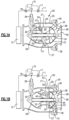
- a valving system 20 is illustrated in Figure 1A .
- a piston 21 slides on a central support tube 22.
- An extending arm 23 connects a radially outer piston stop portion 27 to a radially inner sliding portion 24.
- Inner sliding portion 24 is supported on a support tube 22.
- a housing 25 encloses the piston 21 and includes a plurality of arms 26 which are circumferentially spaced.
- a control tube 28 selectively controls an air supply either from an ambient source 11, or from a compressor 15 such as may be included in an associated gas turbine engine. Ambient air from line 11 may pass through a valve 17 to connection 16, into tube 28 and into passages 30/32 and outwardly through holes 34.
- a control 10 may open a valve 18, and close valve 17 to supply high pressure air from the compressor 15 through the passages 30/32 and holes 34. This air passes into a chamber 50 which is forward of a face 51 of the piston 21.
- Piston 21 has a forward end 36 which is shown spaced from a stop 38 on the housing in the position illustrated in Figure 1A . Another portion 39 of the stop on the housing 25 is also illustrated.
- control 10 closes valve 17 and opens valve 18.
- Valves 17 and 18 can also be replaced by a servo valve or a solenoid valve.
- pressurized air is delivered into the chamber 50. This acts on face 51 forcing the piston 21 to the left, such that end 36 is spaced from stop 38/39.
- a chamber 52 on an opposed side of face 51 from chamber 50 is communicating with ambient pressure through a tap 29.
- Control 10 will send pressure to chamber 50 to move the pistons to this position when it is desired to have air pass through chamber 54, and to an outlet 56. Again, one situation where this may be desirable is to vent the compressor 15 associated with a gas turbine engine such as at start up. Also, venting may be utilized when high temp bleed air is desired for other purposes, e.g. anti-ice valves.
- valve 20 closes valve 18 and opens valve 17 or other similar device as above.
- connection 30/32 and hole 34 receive ambient pressure into chamber 50.
- the pressurized air in chamber 54 behind a face 55 of the piston 21 drives the piston to a closed position such as shown in Figure 1B wherein end 36 abuts stops 38/39 and air will not flow from the inlet chamber 54 to the outlet 56.
- piston 21 of materials (such as Nickel based alloys, as examples Inconel ® or Haynes ® 282) which can withstand higher pressures and temperatures while maintaining high strength limits.
- materials such as Nickel based alloys, as examples Inconel ® or Haynes ® 282
- bushings 40 and 46 are mounted within the sliding portion 24.
- the guide tube 22 may be formed of high temperature/high strength material such as nickel alloys including Inconel ® 718 and Haynes ® 282. However, lower strength, good wear resistant materials may also be utilized such as Stellite 6B ® or Stellite 3 ® .
- the tube 22 may be coated with a chrome-carbide hardcoat, or other hardcoats to improve wear resistance.
- Stellite is a trademark for cobalt-based alloys, with significant proportions of chromium and tungsten.
- bushing 40 is received in a groove 42, and bushing 46 is received within a groove 44.
- Each of the bushings 40 and 46 have a secondary retention 48 abutting an end 150 of the sliding portion 24.
- bushings 40/46 are force fit onto grooves 42/49.
- High wear resistant material is typically harder to machine then the material that would otherwise form the piston 21.
- Stellite 6B ® or Stellite 3 ® may be utilized.
- Stellites may not be able to withstand the temperatures while maintaining a high enough strength limit for the pressures and loads applied.
- the bushings are disposed in a location of low stress only and as an effect of press fit are kept in a compressively loaded scenario with minimal tensile loads.
- the body of the piston 21 can otherwise be formed by materials which are suited for withstanding such challenges.
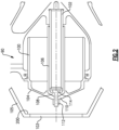
- Figure 2 shows another embodiment 90 wherein the piston 100 has a distinct forward face 104 selectively abutting a stop 200 on a housing 105 which includes the outlet 103.
- the valve 90 may otherwise operate as the Figure 1A-1C embodiment and be driven to abut the stop 200, or be withdrawn from the stop 200.
- inner sliding portion 106 is received on support tube 102.
- Sliding portion 106 includes a forward end 108 abutting a radially inner end 110 of the forward face 104. Forward face acts as the arm to connect the inner and outer portions.
- a bolt 114 is received on a threaded member 112 to force the section 110 against the section 108 and secure the inner sliding portion 106.
- the inner sliding portion 106 may be formed of a material having good wear resistance, whereas the remainder of the piston 100 may be formed of a material similar to that used for portion 27.
- Figure 3 shows yet another embodiment 120 wherein the piston 122 has the forward face 124 and an inner sliding portion 128 sliding on a fixed tube 126.
- the inner sliding portion 128 is welded to the remainder of the piston body.
- a stop 130 is shown abutting a radially inner end 132 of the forward face 124.
- Weld materials 134 and 136 weld the structure together. Again, the material for the sliding portion 128 may have good wear resistance whereas the material for the remainder of the piston body may be selected for resistance to high pressure temperatures.
- the radially inner sliding portions 106/128 can be read as a bushing.
- Figure 2 or 3 embodiments could be substituted in a valve arranged as in the Figure 1A-1C embodiment, and the bushings as shown in Figure 1A and 1B may be incorporated into a valve structure as in the Figure 2 or 3 embodiments.
- An inline valve under this disclosure could be said to include a sliding piston having a radially outer stop portion with a forward end, and a radially inner sliding portion connected to the radially outer stop portion by an arm.
- a housing includes an outer housing body surrounding the piston. The housing has a stop surface selectively in contact with the forward end of the radially outer stop portion of the piston to block flow for a housing inlet to a housing outlet.
- the radially inner sliding portion slides on a support tube.
- the radially inner sliding portion has a bushing formed of a first material having a better wear resistance than a second material forming the radially outer stop portion of the piston. The second material has a greater resistance to high temperature and pressure than the first material
- An inline valve under this disclosure could be said to include a sliding piston having a radially outer stop portion with a forward end, and a radially inner sliding portion connected to the radially outer stop portion by an arm.
- a housing includes an outer housing body surrounding the piston. The housing has a stop surface selectively in contact with the forward end of the radially outer stop portion of the piston to block flow for a housing inlet to a housing outlet.
- the radially inner sliding portion slides on a support tube and has a bushing formed of a first material having a better wear resistance than a second material forming the radially outer stop portion of the piston. The second material has a greater resistance to high temperature and pressure than the first material.
- a vent valve for a compressor associated with a gas turbine engine under this disclosure could be said to include a valve inlet to be connected to a compressor in a gas turbine engine.
- a sliding piston has a radially outer stop portion with a forward end, and a radially inner sliding portion is connected to the radially outer stop portion by an arm.
- a housing includes an outer housing body surrounding the piston, and the housing has a stop surface selectively in contact with the forward end of the radially outer stop portion of the piston to block flow for a housing inlet to a housing outlet.
- the radially inner sliding portion slides on a support tube, and has a bushing formed of a first material having a better wear resistance than a second material forming the radially outer stop portion of the piston.
- the second material has a greater resistance to high temperature and pressure than the first material.
- the first material is a cobalt based allow including chromium and tungsten, and the second material is a nickel alloy.
- An inline valve under this disclosure could alternatively be said to include a sliding piston having a radially outer stop portion with a forward end.
- a radially inner sliding portion is connected to the radially outer stop portion by an arm.
- a housing includes an outer housing body surrounding the piston. The housing has a stop surface selectively in contact with the forward end of the radially outer stop portion of the piston to block flow for a housing inlet to a housing outlet.
- the radially inner sliding portion slides on a support tube.
- the radially inner sliding portion has bushing means having a better wear resistance than a resistance means forming the radially outer stop portion of the piston.
- the resistance means has a greater resistance to high temperature and pressure than the bushing means.
- the bushing means is formed of a cobalt bared alloy including chromium and tungsten, and the resistance means is a nickel alloy.
Landscapes
- Engineering & Computer Science (AREA)
- General Engineering & Computer Science (AREA)
- Mechanical Engineering (AREA)
- Life Sciences & Earth Sciences (AREA)
- Sustainable Development (AREA)
- Physics & Mathematics (AREA)
- Fluid Mechanics (AREA)
- Sliding Valves (AREA)
Applications Claiming Priority (1)
| Application Number | Priority Date | Filing Date | Title |
|---|---|---|---|
| US17/508,485 US11982358B2 (en) | 2021-10-22 | 2021-10-22 | Inline pneumatic valve with internal bushing |
Publications (1)
| Publication Number | Publication Date |
|---|---|
| EP4191069A1 true EP4191069A1 (de) | 2023-06-07 |
Family
ID=83903429
Family Applications (1)
| Application Number | Title | Priority Date | Filing Date |
|---|---|---|---|
| EP22202790.6A Pending EP4191069A1 (de) | 2021-10-22 | 2022-10-20 | Pneumatisches inline-ventil mit interner buchse |
Country Status (2)
| Country | Link |
|---|---|
| US (1) | US11982358B2 (de) |
| EP (1) | EP4191069A1 (de) |
Citations (2)
| Publication number | Priority date | Publication date | Assignee | Title |
|---|---|---|---|---|
| US3521661A (en) * | 1967-07-28 | 1970-07-28 | Stewart Warner Corp | Hot gas valve |
| EP3246607A1 (de) * | 2016-05-19 | 2017-11-22 | Hamilton Sundstrand Corporation | In-line-absperrventile |
Family Cites Families (17)
| Publication number | Priority date | Publication date | Assignee | Title |
|---|---|---|---|---|
| US3092132A (en) * | 1961-05-15 | 1963-06-04 | Rotax Ltd | Compressed air or other gas control valves |
| US3529619A (en) * | 1969-07-09 | 1970-09-22 | Hercules Inc | Valve device |
| US3865128A (en) * | 1972-09-08 | 1975-02-11 | Vijay K Zadoo | Pressure regulating and shut-off valve |
| US3825026A (en) | 1973-06-01 | 1974-07-23 | Vapor Corp | Inline valve |
| GB1546022A (en) * | 1977-02-25 | 1979-05-16 | Coal Ind | Fluid operable valves |
| DE3610534A1 (de) * | 1986-03-27 | 1987-10-01 | Porsche Ag | Ventilfuehrung fuer ein abgasventil einer brennkraftmaschine |
| DE3610965A1 (de) * | 1986-04-02 | 1987-10-08 | Mokveld Valves Bv | Rueckschlagventil |
| WO1989011611A1 (en) | 1988-05-18 | 1989-11-30 | Valvtec Pty Ltd | Backflow preventer valve |
| US5012841A (en) * | 1989-08-24 | 1991-05-07 | Keystone International Holdings Corp. | Pressure reducing and conditioning valves |
| US5540252A (en) * | 1994-07-21 | 1996-07-30 | United Technologies Corporation | Pneumatically stabilized inline valve |
| US5477673A (en) * | 1994-08-10 | 1995-12-26 | Pratt & Whitney Canada Inc. | Handling bleed valve |
| US6122905A (en) * | 1998-02-13 | 2000-09-26 | Pratt & Whitney Canada Corp. | Compressor bleed valve |
| DE19828199C2 (de) * | 1998-06-25 | 2000-04-20 | Daimler Chrysler Ag | Absperrventil |
| US6981842B2 (en) * | 2003-07-22 | 2006-01-03 | Honeywell International, Inc. | Bleed valve system |
| US8910653B2 (en) * | 2012-11-08 | 2014-12-16 | Hamilton Sundstrand Corporation | Valve assembly |
| US9784184B2 (en) | 2015-03-16 | 2017-10-10 | Hamilton Sundstrand Corporation | Self-actuated, in-line bleed valve |
| US10865715B2 (en) | 2018-12-07 | 2020-12-15 | Raytheon Technologies Corporation | Passive stability bleed valve with adjustable reference pressure regulator and remote override capability |
-
2021
- 2021-10-22 US US17/508,485 patent/US11982358B2/en active Active
-
2022
- 2022-10-20 EP EP22202790.6A patent/EP4191069A1/de active Pending
Patent Citations (2)
| Publication number | Priority date | Publication date | Assignee | Title |
|---|---|---|---|---|
| US3521661A (en) * | 1967-07-28 | 1970-07-28 | Stewart Warner Corp | Hot gas valve |
| EP3246607A1 (de) * | 2016-05-19 | 2017-11-22 | Hamilton Sundstrand Corporation | In-line-absperrventile |
Also Published As
| Publication number | Publication date |
|---|---|
| US11982358B2 (en) | 2024-05-14 |
| US20230126388A1 (en) | 2023-04-27 |
Similar Documents
| Publication | Publication Date | Title |
|---|---|---|
| US6698712B2 (en) | Ball valve assembly | |
| US10228074B2 (en) | Pneumatic mixing valve | |
| US6446657B1 (en) | Aircraft air control valve apparatus | |
| US11746904B2 (en) | Reinforced sealing rings | |
| EP3643951B1 (de) | Verfahren zur modifizierung einer ventilanordnung | |
| CN204878988U (zh) | 致动器装置 | |
| US20070040136A1 (en) | Fluid control valve device | |
| JP2004162918A (ja) | 圧力バランス取りピストンを備える弁およびそれに関わる方法 | |
| JP2016506479A (ja) | 大きな流量容量のために流体力制御を行う電気油圧式の圧力低減及び解放バルブ | |
| US20170268659A1 (en) | Hydraulic Control Device for an Automatic Transmission | |
| US20150292525A1 (en) | Servo Valve | |
| KR20230088631A (ko) | 고압 가스 밀봉 | |
| CN107654288A (zh) | 涡轮机废气门 | |
| CN107061824A (zh) | 一种多功能瓶阀 | |
| US20210062922A1 (en) | Flow control valve having a sealing gasket with a secondary sealing surface | |
| EP3665407A1 (de) | Verstärkte dichtringe | |
| US11982358B2 (en) | Inline pneumatic valve with internal bushing | |
| CN110778741B (zh) | 单阀座双向密封结构及球阀 | |
| US10824172B1 (en) | Pneumatic controllers, pneumatically controlled inline valves, and methods of actuating inline valves | |
| US20150309515A1 (en) | Dual pressure shuttle valve | |
| US10859178B2 (en) | Bleed valves | |
| EP4060172A1 (de) | Bypassventilanordnung einer turboladerturbine | |
| US20220196154A1 (en) | Butterfly valve with vibration resistant mount | |
| US11143183B2 (en) | Gear pump bearing with hybrid pad shutoff | |
| EP4485119B1 (de) | Druckregelventil |
Legal Events
| Date | Code | Title | Description |
|---|---|---|---|
| PUAI | Public reference made under article 153(3) epc to a published international application that has entered the european phase |
Free format text: ORIGINAL CODE: 0009012 |
|
| STAA | Information on the status of an ep patent application or granted ep patent |
Free format text: STATUS: THE APPLICATION HAS BEEN PUBLISHED |
|
| AK | Designated contracting states |
Kind code of ref document: A1 Designated state(s): AL AT BE BG CH CY CZ DE DK EE ES FI FR GB GR HR HU IE IS IT LI LT LU LV MC ME MK MT NL NO PL PT RO RS SE SI SK SM TR |
|
| STAA | Information on the status of an ep patent application or granted ep patent |
Free format text: STATUS: REQUEST FOR EXAMINATION WAS MADE |
|
| 17P | Request for examination filed |
Effective date: 20231207 |
|
| RBV | Designated contracting states (corrected) |
Designated state(s): AL AT BE BG CH CY CZ DE DK EE ES FI FR GB GR HR HU IE IS IT LI LT LU LV MC ME MK MT NL NO PL PT RO RS SE SI SK SM TR |
|
| STAA | Information on the status of an ep patent application or granted ep patent |
Free format text: STATUS: EXAMINATION IS IN PROGRESS |
|
| 17Q | First examination report despatched |
Effective date: 20250624 |