EP3461253B1 - Sélection de voies vasculaires à partir d'images - Google Patents
Sélection de voies vasculaires à partir d'images Download PDFInfo
- Publication number
- EP3461253B1 EP3461253B1 EP17798882.1A EP17798882A EP3461253B1 EP 3461253 B1 EP3461253 B1 EP 3461253B1 EP 17798882 A EP17798882 A EP 17798882A EP 3461253 B1 EP3461253 B1 EP 3461253B1
- Authority
- EP
- European Patent Office
- Prior art keywords
- vascular
- path
- paths
- image
- processor
- Prior art date
- Legal status (The legal status is an assumption and is not a legal conclusion. Google has not performed a legal analysis and makes no representation as to the accuracy of the status listed.)
- Active
Links
- 230000002792 vascular Effects 0.000 title claims description 322
- 238000000034 method Methods 0.000 claims description 99
- 210000004204 blood vessel Anatomy 0.000 claims description 15
- 230000017531 blood circulation Effects 0.000 claims description 13
- 230000008859 change Effects 0.000 claims description 4
- 230000011218 segmentation Effects 0.000 description 38
- 230000006870 function Effects 0.000 description 30
- 238000004590 computer program Methods 0.000 description 18
- 230000033001 locomotion Effects 0.000 description 12
- 238000012545 processing Methods 0.000 description 11
- 210000005166 vasculature Anatomy 0.000 description 9
- 238000013459 approach Methods 0.000 description 8
- 238000010586 diagram Methods 0.000 description 8
- 238000003860 storage Methods 0.000 description 8
- 210000003484 anatomy Anatomy 0.000 description 7
- 238000003384 imaging method Methods 0.000 description 6
- 238000004458 analytical method Methods 0.000 description 5
- 238000010801 machine learning Methods 0.000 description 5
- 241000270295 Serpentes Species 0.000 description 4
- 238000001514 detection method Methods 0.000 description 4
- 230000008569 process Effects 0.000 description 4
- 230000008901 benefit Effects 0.000 description 3
- 239000008280 blood Substances 0.000 description 3
- 210000004369 blood Anatomy 0.000 description 3
- 230000000747 cardiac effect Effects 0.000 description 3
- 150000001875 compounds Chemical class 0.000 description 3
- 238000009792 diffusion process Methods 0.000 description 3
- 238000001914 filtration Methods 0.000 description 3
- 210000002216 heart Anatomy 0.000 description 3
- 239000000203 mixture Substances 0.000 description 3
- 230000003287 optical effect Effects 0.000 description 3
- 230000002829 reductive effect Effects 0.000 description 3
- 238000010521 absorption reaction Methods 0.000 description 2
- 230000009471 action Effects 0.000 description 2
- 238000013528 artificial neural network Methods 0.000 description 2
- 239000002872 contrast media Substances 0.000 description 2
- 238000012937 correction Methods 0.000 description 2
- 238000000326 densiometry Methods 0.000 description 2
- 238000000605 extraction Methods 0.000 description 2
- 230000001965 increasing effect Effects 0.000 description 2
- 239000004615 ingredient Substances 0.000 description 2
- 230000003993 interaction Effects 0.000 description 2
- 230000002452 interceptive effect Effects 0.000 description 2
- 230000000670 limiting effect Effects 0.000 description 2
- 238000004519 manufacturing process Methods 0.000 description 2
- 230000000877 morphologic effect Effects 0.000 description 2
- 239000013307 optical fiber Substances 0.000 description 2
- 230000000644 propagated effect Effects 0.000 description 2
- 239000000126 substance Substances 0.000 description 2
- 208000024891 symptom Diseases 0.000 description 2
- 230000007704 transition Effects 0.000 description 2
- 230000000007 visual effect Effects 0.000 description 2
- 230000001154 acute effect Effects 0.000 description 1
- 238000007792 addition Methods 0.000 description 1
- 210000000709 aorta Anatomy 0.000 description 1
- 210000001367 artery Anatomy 0.000 description 1
- 230000003190 augmentative effect Effects 0.000 description 1
- 230000006399 behavior Effects 0.000 description 1
- 238000012512 characterization method Methods 0.000 description 1
- 238000006243 chemical reaction Methods 0.000 description 1
- 238000007621 cluster analysis Methods 0.000 description 1
- 238000012790 confirmation Methods 0.000 description 1
- 238000010276 construction Methods 0.000 description 1
- 210000004351 coronary vessel Anatomy 0.000 description 1
- 230000001186 cumulative effect Effects 0.000 description 1
- 238000003066 decision tree Methods 0.000 description 1
- 230000003247 decreasing effect Effects 0.000 description 1
- 230000001419 dependent effect Effects 0.000 description 1
- 238000011161 development Methods 0.000 description 1
- 230000018109 developmental process Effects 0.000 description 1
- 238000003745 diagnosis Methods 0.000 description 1
- 238000005516 engineering process Methods 0.000 description 1
- 238000003709 image segmentation Methods 0.000 description 1
- 238000010348 incorporation Methods 0.000 description 1
- 230000001939 inductive effect Effects 0.000 description 1
- 230000002401 inhibitory effect Effects 0.000 description 1
- 238000002347 injection Methods 0.000 description 1
- 239000007924 injection Substances 0.000 description 1
- 238000007689 inspection Methods 0.000 description 1
- 210000005240 left ventricle Anatomy 0.000 description 1
- 238000005259 measurement Methods 0.000 description 1
- 238000012986 modification Methods 0.000 description 1
- 230000004048 modification Effects 0.000 description 1
- 210000004165 myocardium Anatomy 0.000 description 1
- 238000005457 optimization Methods 0.000 description 1
- 210000000056 organ Anatomy 0.000 description 1
- 230000000144 pharmacologic effect Effects 0.000 description 1
- 238000003825 pressing Methods 0.000 description 1
- 230000005855 radiation Effects 0.000 description 1
- 230000002787 reinforcement Effects 0.000 description 1
- 230000004233 retinal vasculature Effects 0.000 description 1
- 238000010845 search algorithm Methods 0.000 description 1
- 239000004065 semiconductor Substances 0.000 description 1
- 238000012706 support-vector machine Methods 0.000 description 1
- 238000012360 testing method Methods 0.000 description 1
- 210000003462 vein Anatomy 0.000 description 1
- 238000012800 visualization Methods 0.000 description 1
Images


Classifications
-
- A—HUMAN NECESSITIES
- A61—MEDICAL OR VETERINARY SCIENCE; HYGIENE
- A61B—DIAGNOSIS; SURGERY; IDENTIFICATION
- A61B6/00—Apparatus for radiation diagnosis, e.g. combined with radiation therapy equipment
- A61B6/50—Clinical applications
- A61B6/504—Clinical applications involving diagnosis of blood vessels, e.g. by angiography
-
- A—HUMAN NECESSITIES
- A61—MEDICAL OR VETERINARY SCIENCE; HYGIENE
- A61B—DIAGNOSIS; SURGERY; IDENTIFICATION
- A61B6/00—Apparatus for radiation diagnosis, e.g. combined with radiation therapy equipment
- A61B6/48—Diagnostic techniques
- A61B6/481—Diagnostic techniques involving the use of contrast agents
-
- A—HUMAN NECESSITIES
- A61—MEDICAL OR VETERINARY SCIENCE; HYGIENE
- A61B—DIAGNOSIS; SURGERY; IDENTIFICATION
- A61B6/00—Apparatus for radiation diagnosis, e.g. combined with radiation therapy equipment
- A61B6/52—Devices using data or image processing specially adapted for radiation diagnosis
- A61B6/5211—Devices using data or image processing specially adapted for radiation diagnosis involving processing of medical diagnostic data
- A61B6/5217—Devices using data or image processing specially adapted for radiation diagnosis involving processing of medical diagnostic data extracting a diagnostic or physiological parameter from medical diagnostic data
-
- G—PHYSICS
- G06—COMPUTING; CALCULATING OR COUNTING
- G06T—IMAGE DATA PROCESSING OR GENERATION, IN GENERAL
- G06T7/00—Image analysis
- G06T7/0002—Inspection of images, e.g. flaw detection
- G06T7/0012—Biomedical image inspection
-
- G—PHYSICS
- G06—COMPUTING; CALCULATING OR COUNTING
- G06T—IMAGE DATA PROCESSING OR GENERATION, IN GENERAL
- G06T7/00—Image analysis
- G06T7/10—Segmentation; Edge detection
- G06T7/11—Region-based segmentation
-
- G—PHYSICS
- G06—COMPUTING; CALCULATING OR COUNTING
- G06T—IMAGE DATA PROCESSING OR GENERATION, IN GENERAL
- G06T7/00—Image analysis
- G06T7/10—Segmentation; Edge detection
- G06T7/12—Edge-based segmentation
-
- G—PHYSICS
- G06—COMPUTING; CALCULATING OR COUNTING
- G06T—IMAGE DATA PROCESSING OR GENERATION, IN GENERAL
- G06T7/00—Image analysis
- G06T7/10—Segmentation; Edge detection
- G06T7/149—Segmentation; Edge detection involving deformable models, e.g. active contour models
-
- G—PHYSICS
- G16—INFORMATION AND COMMUNICATION TECHNOLOGY [ICT] SPECIALLY ADAPTED FOR SPECIFIC APPLICATION FIELDS
- G16H—HEALTHCARE INFORMATICS, i.e. INFORMATION AND COMMUNICATION TECHNOLOGY [ICT] SPECIALLY ADAPTED FOR THE HANDLING OR PROCESSING OF MEDICAL OR HEALTHCARE DATA
- G16H10/00—ICT specially adapted for the handling or processing of patient-related medical or healthcare data
- G16H10/60—ICT specially adapted for the handling or processing of patient-related medical or healthcare data for patient-specific data, e.g. for electronic patient records
-
- G—PHYSICS
- G16—INFORMATION AND COMMUNICATION TECHNOLOGY [ICT] SPECIALLY ADAPTED FOR SPECIFIC APPLICATION FIELDS
- G16H—HEALTHCARE INFORMATICS, i.e. INFORMATION AND COMMUNICATION TECHNOLOGY [ICT] SPECIALLY ADAPTED FOR THE HANDLING OR PROCESSING OF MEDICAL OR HEALTHCARE DATA
- G16H50/00—ICT specially adapted for medical diagnosis, medical simulation or medical data mining; ICT specially adapted for detecting, monitoring or modelling epidemics or pandemics
- G16H50/30—ICT specially adapted for medical diagnosis, medical simulation or medical data mining; ICT specially adapted for detecting, monitoring or modelling epidemics or pandemics for calculating health indices; for individual health risk assessment
-
- G—PHYSICS
- G06—COMPUTING; CALCULATING OR COUNTING
- G06T—IMAGE DATA PROCESSING OR GENERATION, IN GENERAL
- G06T2207/00—Indexing scheme for image analysis or image enhancement
- G06T2207/20—Special algorithmic details
- G06T2207/20076—Probabilistic image processing
-
- G—PHYSICS
- G06—COMPUTING; CALCULATING OR COUNTING
- G06T—IMAGE DATA PROCESSING OR GENERATION, IN GENERAL
- G06T2207/00—Indexing scheme for image analysis or image enhancement
- G06T2207/20—Special algorithmic details
- G06T2207/20092—Interactive image processing based on input by user
- G06T2207/20096—Interactive definition of curve of interest
-
- G—PHYSICS
- G06—COMPUTING; CALCULATING OR COUNTING
- G06T—IMAGE DATA PROCESSING OR GENERATION, IN GENERAL
- G06T2207/00—Indexing scheme for image analysis or image enhancement
- G06T2207/30—Subject of image; Context of image processing
- G06T2207/30004—Biomedical image processing
- G06T2207/30101—Blood vessel; Artery; Vein; Vascular
Definitions
- the present disclosure relates in general to the field of anatomical segmentation and more particularly, to manually assisted segmentation of branched vascular anatomy.
- Vascular segmentation and feature identification is a preliminary stage of image-based measurement of vascular state. Though many stages of vascular segmentation and feature identification can be performed based primarily on automated analysis, relevant image features are often of low contrast and/or embedded in a complex environment comprising elements of ambiguous geometry and extraneous features. Human supervision may be introduced into the workflow to make corrections and help ensure quality of results, resulting in a semi-automated process, for example as in the Livewire and related procedures (discussed, for example, in Ryan Dickie, et al.; Live-vessel: Interactive vascular image segmentation with simultaneous extraction of optimal medial and boundary paths. Technical report TR 2009-23, School of Computing Science, Simon Fraser University, Burnaby, BC, Canada, November 2009 ).
- a method of segmenting a vascular image into vascular paths for defining paths of blood flow includes defining first and second targeted vascular path end regions within the vascular image, identifying the positions of vascular portions in the vascular image, and automatically generating a plurality of vascular path options from the identified vascular portions, each vascular path option defining a potential vascular path which extends between the first and second targeted vascular path end regions.
- the method may also include displaying the plurality of vascular path options registered to the vascular image for selection by a user, each of the displayed vascular path options including the first and second targeted vascular path end regions.
- the example method may further include receiving a path option selected by the user for defining a path of blood flow.
- the plurality of paths are automatically generated based on a first set of criteria, and the path option selected by the user is selected based on a second set of criteria.
- the predetermining comprises ranking the vascular path options in an order, based on assessment of a likelihood that each vascular path option corresponds to an actual path of blood flow in blood vessels imaged in the vascular image.
- the predetermining comprises applying a cost function which assigns numerical costs to one or more features related to the vascular path options.
- the cost function assigns numerical costs based on features of a plurality of vascular segment centerlines from which the vascular path option is concatenated.
- the features of the plurality of vascular segment centerlines include one or more from the group consisting of centerline orientation, centerline offset, and a count of centerlines extending from a nodal region.
- the cost function assigns numerical costs based on features of the vascular image over which the vascular path option extends.
- the features of the vascular image include one or more of the group consisting of: continuity of vascular segment image intensity, continuity of vascular segment image width, and the position of a relative change in vascular intensity with respect to a nodal region from which three or more vascular segments extend.
- the predetermining comprises applying a cost function which assigns numerical costs based on an estimated relative position of a vascular segment image in depth, relative to an axis extending perpendicular to a plane of the vascular image.
- the presenting comprises presenting the plurality of vascular path options in a sequential order determined by the order of selection.
- the presenting comprises presenting the plurality of vascular path options simultaneously, and the order of selection corresponds to an order in which the vascular path options are displayed as active for selection.
- each vascular path option defines a vascular path which extends through an image region between the first and second targeted vascular path end regions, ending at a vascular region of the image which is nearest to one of the first and second targeted vascular path end positions.
- a method of editing a vascular path to more accurately delineate a segmentation of a blood vessel in a vascular image includes receiving an indication of a selected region along the segmentation of the blood vessel, defining an energy functional defined as a function of position along the segmentation of the blood vessel, wherein non-zero regions of the energy functional are set based on the position of the selected region.
- the method may also include moving regions of the segmentation in accordance with energy minimization within the non-zero regions of the energy functional.
- energy functional values in the non-zero regions are set based on features of the underlying vascular image.
- energy functional values in the non-zero regions are set based on movement of a user-controlled position indication.
- the user-controlled position indication comprises the indication of the selected region.
- a user interface for semi-automatic segmentation of a vascular path comprising: at least one interface module operable to present an automatically generated default vascular path extending between two target end points; at least one interface module operable to present at least one additional automatically generated vascular path extending between the two target end points.
- the user interface further comprises at least one interface module allowing definition of at least one way point, and operable to present an automatically generated vascular path extending between the two target end points via the at least one way point.
- the user interface further comprises at least one interface module operable to modify a previously defined vascular path by dragging a portion of the vascular path to a new location.
- aspects of the present disclosure may be embodied as a system, a method or a computer program product. Accordingly, aspects of the present disclosure may take the form of an entirely hardware embodiment, an entirely software embodiment (including firmware, resident software, micro-code, etc .) or an embodiment combining software and hardware aspects that may all generally be referred to herein as a "circuit," "module” or “system.” Furthermore, some embodiments of the present disclosure may take the form of a computer program product embodied in one or more computer readable medium(s) having computer readable program code embodied thereon. Implementation of the method and/or system of some embodiments of the disclosure can involve performing and/or completing selected tasks manually, automatically, or a combination thereof. Moreover, according to actual instrumentation and equipment of some embodiments of the method and/or system of the disclosure, several selected tasks could be implemented by hardware, by software or by firmware and/or by a combination thereof, e.g., using an operating system.
- a data processor such as a computing platform for executing a plurality of instructions.
- the data processor includes a volatile memory for storing instructions and/or data and/or a non-volatile storage, for example, a magnetic hard-disk and/or removable media, for storing instructions and/or data.
- a network connection may be provided.
- a display and/or a user input device such as a keyboard or mouse may also be provided.
- the computer readable medium may be a computer readable signal medium or a computer readable storage medium.
- a computer readable storage medium may be, for example, but not limited to, an electronic, magnetic, optical, electromagnetic, infrared, or semiconductor system, apparatus, or device, or any suitable combination of the foregoing.
- a computer readable storage medium may be any tangible medium that can contain, or store a program for use by or in connection with an instruction execution system, apparatus, or device.
- a computer readable signal medium may include a propagated data signal with computer readable program code embodied therein, for example, in baseband or as part of a carrier wave. Such a propagated signal may take any of a variety of forms, including, but not limited to, electro-magnetic, optical, or any suitable combination thereof.
- a computer readable signal medium may be any computer readable medium that is not a computer readable storage medium and that can communicate, propagate, or transport a program for use by or in connection with an instruction execution system, apparatus, or device.
- Program code embodied on a computer readable medium and/or data used thereby may be transmitted using any appropriate medium, including but not limited to wireless, wireline, optical fiber cable, RF, etc., or any suitable combination of the foregoing.
- Computer program code for carrying out operations for some embodiments of the present disclosure may be written in any combination of one or more programming languages, including an object oriented programming language such as Java, Smalltalk, C++ or the like and conventional procedural programming languages, such as the "C" programming language or similar programming languages.
- the program code may execute entirely on the user's computer, partly on the user's computer, as a stand-alone software package, partly on the user's computer and partly on a remote computer or entirely on the remote computer or server.
- the remote computer may be connected to the user's computer through any type of network, including a local area network (LAN) or a wide area network (WAN), or the connection may be made to an external computer (for example, through the Internet using an Internet Service Provider).
- LAN local area network
- WAN wide area network
- Internet Service Provider for example, AT&T, MCI, Sprint, EarthLink, MSN, GTE, etc.
- These computer program instructions may also be stored in a computer readable medium that can direct a computer, other programmable data processing apparatus, or other devices to function in a particular manner, such that the instructions stored in the computer readable medium produce an article of manufacture including instructions which implement the function/act specified in the flowchart and/or block diagram block or blocks.
- the computer program instructions may also be loaded onto a computer, other programmable data processing apparatus, or other devices to cause a series of operational steps to be performed on the computer, other programmable apparatus or other devices to produce a computer implemented process such that the instructions which execute on the computer or other programmable apparatus provide processes for implementing the functions/acts specified in the flowchart and/or block diagram block or blocks.
- the present disclosure in some embodiments thereof, relates to the field of anatomical segmentation and more particularly, to manually assisted segmentation of branched vascular anatomy.
- a broad aspect of some embodiments of the current disclosure relates to methods for combining manual and automatic segmentation techniques, which potentially allows for efficient, reliable vascular tree generation.
- Vascular segmentation is an early step in the characterization of vascular anatomy and function from medical image data for a range of applications, including studies of blood flow.
- automatic segmentation methods typically display degraded performance as requirements become more stringent.
- contrast agents are limited in their usable concentration; injectable contrast agents quickly dilute, limiting available imaging time.
- radiation doses used in some types of imaging are preferably kept to a minimum necessary for reliable visualization.
- imaging quality rapidly degrades with decreased vascular diameter, as the signal intensity approaches the limit of background noise, or even quantum noise inherent to the signal itself.
- vasculature itself is highly complicated in form. This potentially gives rise, particularly in 2-D images, to many cases of ambiguous structure; difficult to resolve to a particular branch structure by inspection at the level of local features.
- Global feature detection is difficult to address by general automatic methods, as interpreting such features potentially relies on particularities of the constraints applicable for a particular structure and/or imaging method.
- Semi-automatic segmentation methods seek to address limitations of purely automatic segmentation methods by augmenting them with human judgement and/or control.
- human intervention is expensive in terms of time, money, and/or availability.
- a goal in some semi-automatic segmentation methods is to reduce human time and/or effort spent in supervising automatic segmentation.
- the goal in some embodiments of the disclosure, may be to bring human intervention in semi-automatic segmentation to the lowest achievable level which is consistent with results of sufficiently quality for the use to which they are applied.
- preferred methods for semi-automatic segmentation may include features which are specific to application in particular problem domains.
- An aspect of some embodiments of the present disclosure relates to cascading methods for semi-automatic vascular segmentation of angiographic images. More particularly, in some embodiments, the aspect relates to cascading methods for semi-automatic segmentation of angiographic images while working within the constraints of producing results in real-time. Optionally, segmentation is completed while a catheter procedure, which may be been used to produce the images, is still underway, while leaving sufficient time for subsequent analysis, e.g ., analysis leading to diagnosis and/or treatment planning.
- the manually supervised operations of the semi-automatic vascular segmentation are structured to cascade through an increasingly attention-demanding set of user operations, where the cascading is stopped once the user is satisfied that a sufficient quality of result has been obtained.
- the cascade is structured so that more likely options are presented earlier and/or with greater emphasis, potentially reducing time and/or effort spent by a user in making selections.
- the order of operations is selected to emphasize getting "close enough" results with minimum input, while also providing an opportunity for the correction of errors in automatically identified results as necessary.
- the method optionally starts with the definition of two vascular path end regions (e.g ., regions within some maximum distance from a selection point); after which a most-likely and automatically detected path is presented to the user for acceptance or rejection.
- two vascular path end regions e.g ., regions within some maximum distance from a selection point
- a most-likely and automatically detected path is presented to the user for acceptance or rejection.
- most-likely e.g ., a suitable cost function
- a plurality of vascular path end region pairs are defined initially, and a corresponding plurality of default options are presented simultaneously, and user interaction is limited still further to correcting defaults.
- definition of one of the endpoints is simplified by defining at least one endpoint at a root position of the vascular tree, positioned such that it may be considered to be at one end of any vascular path leading back from one of its branches.
- definition of a plurality of vascular terminal positions is based on fully automatic detection (e.g ., positions where a vascular skeleton defining vascular centerlines naturally ends), or a semi-automatic method such as positions where a selection line swept out by the user intersects segments of an automatically detected vascular skeletonization.
- a default path is not accepted, in some embodiments, then decreasingly likely (higher cost function scored), automatically suggested paths are optionally presented as available. For example, the user can use a scroll wheel or other control to quickly show alternative paths that extend between some pair of target vascular path end regions.
- the user is provided with a user interface tool which is operable to define a vascular path based on the definition of one or more additional waypoints.
- one or more editing tools are optionally provided, which allow a nearly-acceptable presented alternative to be modified.
- a path may be cut, extended, and/or merged with a portion of another existing path.
- a path is optionally edited along its length, for example, by retracing, redefinition of anchor points, and/or dragging of erroneously segments regions into their correct position.
- a target of the semi-automatic vascular segmentation is the production of one or more vascular paths corresponding to anatomically valid paths of blood flow.
- a vascular path comprises a numerically stored sequence of positions corresponding to vascular image positions.
- the vascular path comprises a vascular center-line.
- the vascular path is defined at one end by a root position, located at the path end, which is for example, within the least-branched vessel the path traverses.
- the vascular path is optionally defined by a terminal position, which is, for example, located within the most-branched vessel the path traverses.
- vascular paths are defined by the concatenation of one or more vascular segments.
- vascular segments are defined by one or more methods, at one or more levels of fidelity.
- a vascular segment may be defined within a skeletonized representation of a vascular image (e.g., a binary pixel-array representation which extends through the detected extent of the vasculature with a one-pixel width).
- a vascular segment optionally comprises a sequence of pixel locations extending between two pixels which mark its end points. The end points are optionally selected by any convenient method, even arbitrarily ( e.g ., by breaking the skeleton into segments of at most N pixels in length).
- vascular segment end points are defined at branches and/or crossings (e .g. , skeleton pixels from which branches lead in at least three directions), and/or at free ends (e.g ., skeleton pixels from which only one branch leads).
- vascular paths are defined separately from one another.
- vascular paths are defined by their different extents along a branched vascular tree (e.g., defined by a particular path of traversing the branches of vascular tree; optionally a vascular tree defined as a set of linked vascular segments).
- a vascular tree is defined by the merger of a set of vascular paths, e.g., paths which share a common vascular segment are also considered to share a common root segment.
- An aspect of some embodiments of the present disclosure relates to methods of selecting vascular paths based on the ordered presentation of automatically generated vascular path options.
- a plurality of path routes extending along detected vascular segments are generated for a pair of end regions.
- the generated path routes are those which reach to segment points which are within some region; optionally the region is defined, for example, as the region within some maximum distance from an end-point. This distinction is relevant, for example, in case one of the end points is not itself on a segment.
- the plurality of path routes is presented as a range of vascular path options in a pre-determined order.
- the pre-determined order is based on a cost function constructed to rank path routes according to criteria (optionally, heuristic criteria) that assign more-likely actual paths of blood flow between two end points a lower cost value than less-likely actual paths of blood flow.
- path routes are presented along with image data from which they derive, for example, as graphical overlays on the image.
- image data is presented as an animated sequence of images, e.g. , images between which the vasculature moves slightly, and/or is viewed from a different angle. Potentially, these differences harness visual capabilities more particular to the user than to the automatic detection algorithm, for example, by emphasizing connectedness among portions of the vasculature which move together.
- cost function criteria include aspects of vascular continuity, vascular branching anatomy, criteria based on the three-dimensional shape of an organ which the vasculature perfuses, vascular image opacity, and/or other criteria.
- automatic segmentation results potentially do not unambiguously distinguish which path, among a plurality of alternative vascular paths between two vascular positions, corresponds to an actual path of blood flow.
- 3-D vascular structures e.g ., vascular structure that is typically visualized extending through two or more layers of depth
- branches of the same vascular tree may appear to cross over each other.
- same-tree crossover is seldom observed in structures which are typically imaged within a single focal plane, such as inner retinal vasculature, ambiguities may arise in cases where distinguishing between venous and arterial structures is difficult.
- dynamic path extending methods such as Livewire, partially mitigate automatic segmentation ambiguities by allowing the definition of waypoints that can be set to force the automatic result into the correct segmentation.
- this is potentially more time-consuming than simply defining start and end points.
- An aspect of some embodiments of the present disclosure relates to methods of editing vascular paths by dragging an erroneously segmented region into alignment with a more correctly segmented position.
- the method comprises receiving an indication of a selected region along the segmentation of the blood vessel.
- the indication comprises a screen coordinate point selection, for example, by pressing a button in conjunction with a particular position of a screen cursor, and/or a gesture input to a touch screen.
- the indication comprises directly selecting an erroneously segmented region.
- the method comprises assigning motion susceptibility characteristics to a segmentation path region surrounding the selected region that enable it to be moved, preferably while maintaining the remainder of the segmentation in a state which is not susceptible to movement.
- the assigning of susceptibility to motion comprises defining an energy functional defined as a function of position along the segmentation of the blood vessel.
- non-zero regions of the energy functional are set based on the position of the selected region.
- the method comprises moving regions of the segmentation in accordance with energy minimization within the non-zero regions of the energy functional.
- motion of the motion-susceptible portion of the segmentation path region is in coordination with movement of a cursor.
- motion of the motion-susceptible portion is at least partially governed by values and/or gradients of image intensity in vicinity of the selected region, such that the selected region behaves as though attracted to vascular regions as it moves.
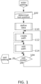
- Figure 1 is a schematic flowchart of a method of defining vascular centerline paths on an angiographic image, according to some exemplary embodiments of the present disclosure.
- an editing mode of a computer program configured for interactive vascular path definition via user interaction through a user interface is activated.
- a root position (corresponding, for example, to root positions 401, 501 of Figures 4A-4F and 5A-5F ) is defined.
- the root position is the vascular position visible in the image which is topologically nearest to the region where blood enters or exits the heart. In the coronary arteries, for example, the root position is topologically nearest to the region where blood exits the left ventricle into the aorta.
- the root position is manually defined, for example, by clicking on or touching (via a user interface device) a point in the image; and/or by selecting, moving, and/or confirming an automatically defined root position.
- automatic detection of one or more candidates for the root position is performed, for example, based on the timing and/or location of dye appearance in an image time series immediately after injection; and/or based on morphological criteria such as vascular thickness, branch order and/or orientation, etc.
- the defined root position is used as an input for the definition of path data including listing of alternative path options and path option costs, for example as described in relation to Figure 2 .
- a vascular path representing a path of continuous vascular connection between some point in a vascular tree image and the root position is optionally defined (and/or selected, for example, based on the listing of path alternative path options and path option costs defined at block 110 ). Examples of the implementation of details of block 112 are described in relation to Figure 3A .
- vascular path representing a previously defined path of continuous vascular connection between some point in a vascular tree image and the root position is optionally edited. Examples of the implementation of details of block 114 are described in relation to Figure 3B .
- FIG. 2 is a schematic flowchart of a method of generating vascular path options from a vascular image, according to some exemplary embodiments of the present disclosure.
- vascular skeleton graph 206 is split into branches.
- the vascular skeleton graph is derived from image processing of an angiographic image. Images 400 of Figures 4A-4F and 500 of Figures 5A-5F are examples of the source images from which the vascular skeleton graph is derived.
- the vascular skeleton graph is comprised of vascular centerlines. An example of the extraction of vascular centerlines (which in some embodiments uses anisotropic diffusion, Frangi filtering, and hysteresis thresholding, followed by binary thinning) is described, for example, in relation to block 20 of Figure 14 of International Patent Publication No.
- WO2014/111927 to the applicant, filed on January 15, 2014 .
- the basis of the method used is similar to that introduced by Weickert in "A Scheme for Coherence-Enhancing Diffusion Filtering with Optimized Rotation Invariance” and/or “Anisotropic Diffusion in Image Processing” (Thesis 1996 ).
- the vascular skeleton graph 206 is split into branches.
- this comprises noting pixels at which three or more skeleton segments converge (e.g., pixels with three or more neighbors; optionally, short spurs are excluded from consideration), and assigning these points to be path breaks.
- branches connect to which (connection may be merely apparent, as the branches may also cross one another and/or approach closely enough to appear to merge).
- the result of the operations of block 208 is branch list 210.
- branch list 210 are potentially linked into loops, either due to the actual underlying anatomy (for example, the development of shunting vessels), and/or due to apparent connection arising from vascular near approaches and/or crossings at the provided angle and/or resolution of the image.
- branches preserved in the branch list are only those for which a continuously connected route exists to a root position (e.g ., root positions 401, 501 of Images 4A-4F and 5A-5F ) on the vascular tree.
- a root position e.g ., root positions 401, 501 of Images 4A-4F and 5A-5F
- the root position is determined, for example, as described in relation to block 102 of Figure 1 .
- paths leading from each branch to the defined root position are calculated, for example, by use of a search algorithm.
- a search algorithm there is more than one such path available, for example due to crossings, close approaches, or other ambiguities present in the image, as previously mentioned.
- Paths that internally include the same vascular segment more than once are optionally excluded from this list (to avoid paths that loop and/or double back on themselves).
- the data structure resulting from the operations of block 212 comprises path list 214.
- path list 214 comprises each non-excluded path identified that extends between the root position and each vascular skeleton segment.
- path costs for each path in path list 214 are calculated to produce a path cost list 218.
- Path cost list 218, in some embodiments, is structured so that members of a potential plurality of paths in path list 214 reaching from any vascular segment to the root can be rank ordered for likelihood of being an actual path of blood flow. Use of path list 214 and/or path cost list 218 is described further in connection with operations of block 112 of Figure 1 , for example as detailed in relation to Figure 3A .
- Path cost criteria are optionally evaluated, for example, to receiving a binary value (0 or 1, for example), a ranked value, and/or a score on a continuous scale. Path cost criteria optionally add, multiply, or are otherwise combined into an overall cost function.
- results of machine learning are used to assign criteria cost values, and/or contribution to overall cost relative to other criteria.
- a machine learning technique comprises one or more implementations of decision tree learning, association rule learning, an artificial neural network, inductive logic programming, a support vector machine, cluster analysis, Bayesian networks, reinforcement learning, representation learning, similarity and metric learning, and/or a technique related to machine learning.
- the machine learning is optionally based on a set of angiographic images which have been separately marked for vascular tree morphology, and/or based on results of self-learning.
- path costs recorded in the path cost list 218 are calculated with respect to one or more of the following considerations and/or criteria.
- vascular skeleton segment connection points are referred to as nodes.
- Nodes may be defined as single pixels, or optionally, as regions of larger size (e.g., a radius of 2, 3, 4, 5 or more pixels) within which three or more vascular skeleton segments meet.
- the overall cost function which is applicable to a node depends at least in part on a node type classification.
- the vascular skeleton will show four branches arising from approximately the region of a central node.
- the corresponding vascular skeleton is optionally analyzed as defining a crossing-type node.
- the nodes is optionally defined as a junction node from which three vascular skeleton branches arise. Cost function criteria applicable to these two basic node types are optionally differently assigned.
- junction orders there are other junction orders which can appear in the path list.
- a bifurcation may happen to be at the same position as a vascular crossing point.
- Another situation which potentially arises is where two junction nodes appear so close to one another that they could also be analyzed as four-branched node.
- skeletonization artifacts potentially introduce a slight offset to the same blood vessel on either side of a crossing, making it appear more like two adjacent junction-type nodes.
- Three- and four-branched nodes can also arise where a terminal vascular segment (that is, a vascular segment which is the last segment visible in the image on its branch) happens to have a free end located at or near the position of another vascular segment.
- nodes comprising five, six, or more segments are analyzed as being composed of a suitable combination of junction nodes, crossing nodes, and/or free-end terminations.
- morphological criteria besides branch counts are used in node classification for purposes of cost function assignment.
- some close sequential bifurcations comprise just one continuously oriented pair of segments, while the other two segments run at a relative sharp angle (e.g ., about 90°) relative to one another.
- bifurcation angles typically (though not exclusively) display forward-direction (in the direction of arterial flow) acute angles.
- Backward-branching oblique angles are more likely to signify a crossing-type node.
- regions of vascular crossings may appear as regions of increased radiopacity (due to the cumulative contribution of two overlapping vascular thicknesses), compared to regions of vascular branching.
- r p 3 r d 1 3 + r d 2 3 r d 3 3 + ⁇ + r d n 3 ; with r p 3 being the radius of the parent (trunk) branch, and r d 1 3 , r d 2 3 , r d 3 3 ... r d n 3 being the radii of the respective child branches.
- a vascular segment combination which satisfies Murray's principle at some node is assigned a higher probability of representing a branching-type node, with remaining segments assigned higher probabilities of being free-end terminations, or participants in crossing-type node structures.
- the appropriate cost function for the node is dependent on which analysis of the node-type is correct.
- node-type determination is subject to probabilistic assignment; e.g ., a node is assigned an 80% chance of being a crossing of two vessels, a 15% chance of being a double bifurcation (or trifurcation), and a 5% chance of being a bifurcation in the region of the free end of a terminal vascular segment.
- junction-type and crossing-type nodes there is no explicit classification made in the cost function between junction-type and crossing-type nodes (or free ends, or combinations of any of these types); rather, heuristics are adopted which operate on the basic relative vascular morphologies as such. This approach may be suitable, for example, for certain types of machine learning-based implementations like artificial neural networks. Nevertheless, node type provides a convenient organizing concept for purposes of explaining further vascular path cost function criteria.
- continuity of vascular morphology at nodes is used as a basis of cost function value assignment.
- the convergence of four vascular skeleton branches considered as a potential crossing-type node is optionally analyzed as defining an a priori choice of three directions to continue in (exit-side) from some fourth direction of approach (entrance-side).
- one or more criteria relating to continuity of morphology are applied to determine which exit-side branch is the branch of most likely continuation from a given entrance-side.
- vascular radius wherein the exit-side vascular branch, which is most similar in radius to the entrance-side, receives the correspondingly lowest cost assignment.
- vascular radius is measured as half the apparent width of a filled lumen in the image.
- continuity of image intensity values (which is partially, but not only, a function of radius) is also taken into account, e.g., by direct comparison of intensity values.
- principles of densitometry are applied: for example, the blood vessel is modeled as cylinder of a certain radius filled with a substance having a particular concentration and/or coefficient of absorption; and the cost function is based jointly on continuity of radius and absorption properties that satisfy observed intensity values in the image.
- continuity of direction is a criterion: the exit-side vascular segment that is most similar in direction to the entrance-side segment optionally receives the correspondingly lowest cost assignment as its continuation. It is noted that densitometry differences can also arise based on the orientation of blood vessels in the direction perpendicular to the plane of the image; e.g., a blood vessel appears darker when seen more nearly end-on. Thus, continuity of vascular intensity values is optionally a proxy for continuity of vascular direction in this dimension.
- these criteria include one or more further refinements.
- a criterion of direction applied to a junction may optionally comprise a cost assignment based on the continuing rate and/or direction of angle change before and after a node (e.g ., continuation between two segments having a more similar radius of curvature receives a lower cost assignment). This is potentially of particular relevance for vascular segments that are rounding a bulge of the 3-D heart surface through a portion of the vascular image.
- a criterion of the cost function favors paths along which vascular width monotonically changes (e.g ., increasing in the direction of the root).
- paths from segments A, B, C, D meeting at a junction are treated as "entangled", such that a low cost for a path leading from A ⁇ B corresponding lowers the cost of the path C ⁇ D relative to alternative path C -> B.
- a definitive indication by a user during some stage of vascular tree drawing that path A -> B is a preferred path of vascular flow is similarly entangled to lowering the cost assignment of path C ⁇ D compared to C ⁇ B.
- bifurcation is typical.
- a greater branch number such as trifurcation, is treated as being composed of adjacent bifurcations.
- a junction node at which there is an a priori choice of two directions to continue in (exit-side) from any third direction of approach (entrance-side).
- the heuristic is adopted that the exit-side branch which requires the minimal change in direction through the junction node receives the lower cost assignment.
- cost scoring based on vascular radius similarity is reduced in its influence on the cost function (e.g ., by lower weighting) when a three-way junction node is detected, to account for two thin branches being potentially nearer in size to each other than their mutual trunk.
- radius-based cost functions are assigned in a different way for branching-type nodes; e.g., the thickest vascular segment (which generally lies in the direction of the root position) is given the lowest cost score for both of the two thinner branches.
- a cost score assignment is more particularly based on Murray's principle, wherein paths that better satisfy this theoretical relationship are given correspondingly lower cost scores.
- paths using vascular segments which run in relatively straight and/or continuously arcing lines are optionally scored with lower costs. This is a potential advantage for favoring image features that are "more vascular" in character, as opposed to image features which might end up in the vascular skeleton, but are actually non-vascular in origin. Cost is optionally calculated, for example, based on the total area under the curve (above or below zero) of the derivative of the angle of local vascular segment orientation.
- vascular position in three dimensions is estimated.
- use of this information is part of node classification, and/or used in continuity/consistency cost scoring.
- a vascular tree is known a priori to extend across a three-dimensionally curved surface, such as a surface defined by the shape of the heart muscle.
- parameters of this curved surface are derived from an image shadow delineating boundaries of the shape being followed.
- shapes and/or intensities of the vessels themselves identify shape boundaries. For example, as blood vessels curve to be oriented more inwardly/outwardly from the plane of the image, they potentially begin to appear more radiopaque at some boundary limit as they present a longer absorbing cross-section.
- Vessel rounding a curve in the third dimension may appear to first approach, and then bend away from, some boundary limit in the 2-D image.
- a shell is modeled as comprising two portions, generally occupying different depths, but joined together at such a boundary limit.
- vascular segments are scored for their likely position on the overlying or underlying portion of the shell, while treating the boundary limit as a transition zone. Paths which require abrupt transitions between two different shell portions (particularly away from the boundary limit), are optionally given a higher cost value.
- vessels of the same type which occupy the same anatomical plane may assumed, in some embodiments, to be relatively unlikely to cross over one another.
- a crossing-type node is identified with high probability (additionally or alternatively, where consistency and continuity suggests a vascular crossing with relatively low associated path cost)
- this is also used to increase the estimated likelihood that the two different vessels occupy two separated shell portions.
- other vascular segments which directly contact them are also correspondingly more likely to be in the same shell portion, information which is optionally used to disambiguate assignment of path costs across nearby nodes.
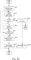
- Figure 3A is a schematic flowchart of a method for selecting and/or defining a particular vascular path option, according to some exemplary embodiments of the present disclosure.
- the operations of Figure 3A correspond to operations occurring within block 112 of Figure 1 .
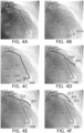
- Figures 4A-4F schematically illustrate selection of vascular path options, according to some exemplary embodiments of the present disclosure.
- Figure 4A shows angiographic image 400 illustrating a portion of a vascular tree 402 (a cardiac vasculature, in the example), including a currently defined root position 401. Contrast of angiographic image 400 is reduced in Figures 4B-4F to make other elements more visible.
- Accepted path list 324 optionally includes paths selected from path list 214, edited paths based on paths in path list 214, and/or paths generated de novo, for example, on the basis of user input.
- path cost list 214 is used in determining default selections from path list 214, and/or an order presentation of additional selections from path list 214, as needed.
- path list 214 potentially comprises a number of vascular paths which are "true" vascular paths in the sense that they are isomorphic with a vascular path that blood follows in the actual patient anatomy in flowing between the root position 401 and the distal end of the vascular path.
- path cost list 218 optionally provides a basis for preferring some vascular paths to others, there may nevertheless be cases where circumstances lead to the true vascular path being less preferred.
- the true vascular path may not even be available in path list 214; for example, due to contrast dropouts and/or other artifacts which may affect the vascular skeletonization.
- a path terminus is indicated (e.g., by a user).
- indication of the path terminus comprises a "hover" cursor input event (e.g ., cursor 405 moved into the vicinity of a potential vascular path, and paused long enough to be detected for processing; a long touch on a touch screen, etc. ) .
- another input event indicates the path terminus: for example, a screen tap.
- the user indication is referred to a region (e.g., a pixel) on the closest available segment which is represented in path list 214.
- the user indication is referred to the region of the segment which is closest to the position of the indication.
- vascular path 407 of Figure 4B extends to a path terminus 407A in the vicinity of cursor 405 at one position.
- cursor 405 is moved as shown in Figure 4C , a different vascular path comprising vascular path 408 appended to vascular path 407 is shown instead, again terminating at path terminus 408A in the vicinity of cursor 405.
- the user indication is referred to the terminal of the segment which is furthest from the root position 401.
- one or more candidate path termini are detected automatically (for example, at the free ends of vascular skeleton segments which are in continuous connection with the root position 401 ).
- a plurality of path termini are optionally indicated by a user as part of a single input action, e.g., by dragging out a path (by cursor movement, touch input, or otherwise) which crosses among several candidate path termini; the indicated termini being taken as the positions at which the dragged out path intersects segments of the vascular skeleton.
- a user is optionally presented with the option to step through candidate path termini (e.g., by a sequence of key presses, finger drags across a touch input screen, scroll wheel movements, or another input), and a selected terminus becomes an indicated path terminus.
- initial paths are defined (and optionally accepted as members of the accepted path list by default) for each of the plurality of candidate path termini.
- the lowest cost available path (based on path cost list 218 ) from path list 214 that is among those reaching to the indicated path terminus is initially selected for presentation to the user.
- the presentation is differentiated as being active for current definition; for example highlighted with special coloration and/or thickness.
- paths from path list 214 are optionally the basis of what is presented, in some embodiments, the actual path shown is derived from an entry in path list 214 by application of an active contour or dynamic "snake" algorithm, for example as described herein.
- a user determines if the correct path (suitable for use as a "true" vascular path) has been displayed or not. If yes, then the flowchart optionally proceeds with the user issuing a confirmation input (for example, a double click, screen tap, key press, or other input) at block 316. The currently selected path is then added to the accepted path list 324, and the flowchart exits block 112 of Figure 1 .
- accepted paths remain displayed; optionally indicated as deselected, for example, by being drawn thinner, with lower contrast, or by another visual indication.
- Figure 4D shows the concatenation of paths 407 and 408 drawn as a member of the accepted path list 324.
- FIG. 4E- 4F For the new position of cursor 405, a corresponding new path option 409 is shown.
- This sequence continues in Figures 4E- 4F, in which new paths 411 and 414 are created.
- each new path is drawn as extending all the way back to root position 401.
- the display is extended only back as far as the first contact with a previously accepted vascular path.
- paths are stored in accepted path list 324 as complete paths extending between terminus and root position, as incremental additions to a vascular tree structure, and/or in another format.
- the flowchart continues; optionally to an option selection event at block 314.
- the option selection event comprises movement of a scroll wheel, a touch screen gesture (for example, a sliding motion), a key press, or another user input event.
- this selection is interpreted in software as indicating that the current path display should move to another candidate ( e . g . the next candidate available in order of cost as defined in path cost list 218 ).
- a plurality of vascular path candidates are presented simultaneously for a single pair of end points, and the selection is used to indicate which candidate should be drawn as actively selected.
- a potential advantage of this variant is to allow more rapid realization that no suitable candidate is available, and/or to allow simultaneous comparison of available options.
- the user may decide that no pre-defined path of path list 214 is suitable for the currently indicated path terminus, and proceed to block 320 in order to define a new path manually. Otherwise, in some embodiments, the flowchart returns to block 311, at which the newly selected path candidate is shown.
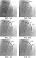
- Figures 5A-5C schematically illustrate selection from among alternative vascular path options, according to some exemplary embodiments of the present disclosure.
- Figure 5A shows angiographic image 500 illustrating a portion of a vascular tree 502 (a cardiac vasculature, in the example), including a currently defined root position 501. Contrast of angiographic image 500 is reduced in Figures 5B-5F to make other elements more visible.
- Figure 5B several previously defined paths 507 are shown. Cursor 505 is shown hovering directly over a vascular location, but the suggested path 509 instead terminates some distance away from the cursor on another vascular location.
- a user has indicated that the next candidate vascular path 511 should be shown, but this vascular path also fails to show what the user intends to add to the accepted path list.
- Figures 5D-5E schematically illustrate a method of manually defining a vascular path option, according to some exemplary embodiments of the present disclosure.
- Figure 5D shows a selection formed by a sequence of position indications (clicks made at different positions of cursor 505, for example), with a line segment drawn between each indication.
- the user has made position indications generally along the intended vascular path.
- root position 501 is considered part of the position indications.
- the user has ended the sequence of position indications (for example, with a double click).
- this results in the operations of block 322, in which the position indications are used to create a new path definition by a form of fitting between them, for example, as described in relation to an active contour algorithm herein.
- the resulting vascular path is optionally added to the accepted path list; and the flowchart of Figure 3A exits from block 112.
- another method of manually defining a vascular path is used, for example, a variation of the Livewire technique, in which a segment position is optionally drawn live as between clicks defining waypoints ("growing" to meet the cursor position from a previous anchor point), rather than all at once after all waypoints are initially defined.
- an active contour method also commonly referred to as a "snake” dynamics method (Kaas et al. 1987) is implemented.
- E int c s 1 2 ⁇ s dx ds + dy ds 2 + ⁇ s d 2 x ds 2 + d 2 y ds 2 2
- GGVF field As a force field, there is calculated in some embodiments the GGVF field (Xu and Prince, 1998) over a Frangi-filtered grayscale image (Frangi et al., 1998), although in general any force field can be used.
- the initial input may be taken from a concatenation of pixels in vascular skeleton segments that connect along a selected path.
- coordinates actually used in the path are repositioned to fall at uniform intervals along the vascular path length (actual center-to-center distances of pixels themselves may be non-uniform due to alternating movements in diagonal and cardinal directions).
- the active contour method iterates, the vascular path positions are drawn into new positions according to the various force and field terms used. Once the path anneals to a sufficiently stable configuration, the force terms are set to zero, and the process stops.
- the forces acting on the anchor points are set to zero (e.g., ⁇ ( s ) , ⁇ ( s ) , and ⁇ ( s ) are set to zero), so that these point remain fixed.
- Points interpolated between them (which may initially be provided as straight lines, by spline interpolation, or by another method) are then subjected to non-zero forces (e.g., ⁇ ( s ) , ⁇ ( s ) and ⁇ ( s ) are set to non-zero values) through a number of iterations of numerically minimizing the energy functionals of (EQU. 2 and EQU. 3) until a sufficiently stable configuration is reached.
- non-zero forces e.g., ⁇ ( s ) , ⁇ ( s ) and ⁇ ( s ) are set to non-zero values
- Figure 3B is a schematic flowchart of a method of manually editing a vascular path, according to some exemplary embodiments of the present disclosure.
- Figure 3B represents an embodiment of the path editing operations of block 114 of Figure 1 .
- Figures 5E-5F schematically illustrate manual editing of a vascular path option, according to some exemplary embodiments of the present disclosure.
- a user makes a position selection along length s of a displayed vascular path (which, in some embodiments, is a path from accepted path list 324 ).
- the position selection comprises a button press at some selected position of a cursor, a gesture on a touch screen, or another input method.
- the position selection is taken to define a dragging point, e.g., dragging point 519A of Figure 5E .
- energy terms of ⁇ ( s ) , ⁇ ( s ) and/or ⁇ ( s ) are set to non-zero only for s within a restricted vicinity of the dragging point.
- the external force field of EQU. 3 is defined to comprise an attractor to the current cursor position, or another position defined by further user interface actions by which the user drags the dragging point to a new location.
- the energy functionals of (EQU. 2 and EQU. 3) are numerically minimized, which may result in the displayed vascular path (e.g., path 517 of Figures 5E-5F ) being displaced around the location of the dragging point.
- display of the vascular path 517 is updated.
- the system determines whether or not the dragging operation is to be ended; for example, based on user input (e.g . release of a button or termination of a touch screen gesture). If not, at block 350 in some embodiments, the user optionally drags the dragging point to a new location, for example, location 519B of Figure 5F . Otherwise, the edited path 517 is updated in the accepted path list 324, and the flow chart ends (optionally, exiting block 114 of Figure 1 ). It should be understood that in some embodiments, the accepted path list is additionally or alternatively updated dynamically during the dragging operation itself.
- Figure 6 schematically illustrates a display 620 of path definitions made concurrently on a plurality of different vascular image views 400, 500, 600, 610, according to some exemplary embodiments of the present disclosure.
- vascular image views 400, 500, 600, 610 each present views from different angles of the same vasculature (e.g ., a region of a cardiac vasculature).
- Partially defined vascular path groups 620, 622, and 624 are shown for views 400, 500, and 600.
- homology among vascular image features is established at least in part on the basis of structures identified in one or more of the vascular skeleton graph 216, the branch list 210, the path list 214, and or the accepted path list 324.
- the accepted path allows identification of homologous vascular features, optionally without detailed 3-D information: for example, based on considerations of branch numbers and/or positions; root positions 611, 601, 501, 401; and/or relative vascular length.
- basic 3-D information for example, angle of view specified within about 45°, 90°, or another greater or lesser amount
- fuller 3-D information is available, for example, vascular centerline positions reconstructed based on stereoscopic projection from two or more images into a common 3-D frame of reference (for example as described in International Patent Publication No. WO2014/111930 to the applicant, filed January 15, 2014 .
- vascular paths generated with respect to one image view are transformed so that they can be superimposed on one or more alternative image views, based on the reconstructed 3-D frame of reference.
- transforms of vascular skeleton graphs 216, branch list 210, and/or path list 214 are performed, for example to assist in validating image processing results.
- missing segment portions in path and/or skeleton data from one image can be filled in from data available in views taken from another image.
- spurious segment portions in one image view are optionally identified, for example, based on their absence and/or lack of connection to the root position in other image views.
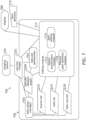
- FIG. 7 is a schematic diagram of software modules and data structures 700 implemented in a system 702 for semi-automated segmentation of vascular paths, according to some exemplary embodiments of the present disclosure.
- Blocks 206, 210, 214, and 218, in some embodiments, comprise data structures generated and/or used by the software modules of the system 702. They correspond, for example, to the correspondingly numbered blocks of Figure 2 .
- Vascular images 701 are provided from an imaging device 750, which is optionally part of the system 702.
- system 702 is stand-alone, or stand-apart from the imaging device 750, with the images are provided, for example, via a remote network connection.
- Block 703 comprises a vascular skeletonizer, configured for producing a skeletonized representation of vascular segments (skeleton graph), for example as described in relation to block 206 of Figure 2 .
- Block 705 comprises a path option manager.
- path option manager 705 comprises software functions for implementing operations of blocks 208, 212, and/or 216 of Figure 2 .
- Editing module 710 comprises sub-modules for handling, for example, operations described in connection with Figures 1 , 3A , and/or 3B .
- option presentation module 712 and/or manual path definition module 716 implement block 112.
- path editing module 714 implements block 114.
- system 702 additionally comprises display 760 and/or input device(s) 770.
- compositions, method or structure may include additional ingredients, steps and/or parts, but only if the additional ingredients, steps and/or parts do not materially alter the basic and novel characteristics of the claimed composition, method or structure.
- a compound or “at least one compound” may include a plurality of compounds, including mixtures thereof.
- method refers to manners, means, techniques and procedures for accomplishing a given task including, but not limited to, those manners, means, techniques and procedures either known to, or readily developed from known manners, means, techniques and procedures by practitioners of the chemical, pharmacological, biological, biochemical and medical arts.
- treating includes abrogating, substantially inhibiting, slowing or reversing the progression of a condition, substantially ameliorating clinical or aesthetical symptoms of a condition or substantially preventing the appearance of clinical or aesthetical symptoms of a condition.
Claims (13)
- Procédé informatisé de segmentation d'une image vasculaire (400, 500, 600, 701) dans des trajets vasculaires pour définir des trajets de circulation sanguine, le procédé comprenant :la réception, dans un processeur (702), de l'image vasculaire ;la définition, par l'intermédiaire du processeur (702), de première et deuxième régions d'extrémité de trajet vasculaire ciblées dans l'image vasculaire ;segmenter, via le processeur (702), l'image vasculaire pour identifier les positions des parties vasculaires dans l'image vasculaire ;la génération automatique, par l'intermédiaire du processeur (702), d'une pluralité de trajets vasculaires à partir des parties vasculaires identifiées, chaque trajet vasculaire définissant un trajet vasculaire potentiel qui s'étend entre les première et deuxième régions d'extrémité de trajet vasculaire ciblées ;la prédétermination, par l'intermédiaire du processeur, un d'ordre de sélection pour les trajets vasculaires par classement des trajets vasculaires, dans un ordre, sur la base de l'évaluation d'une probabilité que chaque trajet vasculaire correspond à un trajet vasculaire réel de circulation sanguine dans les vaisseaux sanguins imagés dans l'image vasculaire par application d'une fonction de coût qui attribue des coûts numériques à une ou plusieurs caractéristiques liées aux trajets vasculaires ;l'affichage, par l'intermédiaire du processeur (702), de la pluralité de trajets vasculaires enregistrés sur l'image vasculaire en tant qu'options de trajet suggérées pour sélection par un utilisateur par l'intermédiaire d'une interface utilisateur (760, 770), chacun des trajets vasculaires affichés comprenant les première et deuxième régions d'extrémité de trajet vasculaire ciblées ; etla réception, dans le processeur (702), du trajet vasculaire que l'utilisateur a sélectionné pour définir un trajet de circulation sanguine ;l'ajustement, par l'intermédiaire du processeur, des coûts attribués aux trajets vasculaires pour d'autres régions d'extrémité de trajet vasculaire ciblées sur la base de la sélection du trajet vasculaire ; etl'ajustement, la suppression ou l'ajout, par l'intermédiaire du processeur (702), des trajets vasculaires pour d'autres régions d'extrémité de trajet vasculaire ciblées qui sont situées dans l'image vasculaire sur la base du coût ajusté respectif des trajets vasculaires pour d'autres régions d'extrémité de trajet vasculaire ciblées.
- Procédé selon la revendication 1, dans lequel la pluralité de trajets sont générés automatiquement sur la base d'un premier ensemble de critères, et le trajet vasculaire sélectionnée par l'utilisateur est sélectionné sur la base d'un deuxième ensemble de critères.
- Procédé selon la revendication 1, dans lequel la fonction de coût attribue des coûts numériques sur la base de caractéristiques d'une pluralité d'axes de segment vasculaire à partir desquels le trajet vasculaire est concaténé.
- Procédé selon la revendication 3, dans lequel les caractéristiques de la pluralité d'axes de segment vasculaire comprennent l'un ou plusieurs dans le groupe constitué de l'orientation de l'axe, le décalage de l'axe et un nombre d'axes s'étendant depuis une région nodale.
- Procédé selon la revendication 1, dans lequel la fonction de coût attribue en outre des coûts numériques sur la base de caractéristiques de l'image vasculaire sur laquelle le trajet vasculaire s'étend.
- Procédé selon la revendication 5, dans lequel les caractéristiques de l'image vasculaire comprennent l'un ou plusieurs dans le groupe constitué de : la continuité de l'intensité de l'image du segment vasculaire, la continuité de la largeur de l'image du segment vasculaire et la position d'un changement relatif de l'intensité vasculaire par rapport à une région nodale depuis laquelle trois segments vasculaires ou plus s'étendent.
- Procédé selon la revendication 1, dans lequel la prédétermination comprend l'application de la fonction de coût pour attribuer en outre des coûts numériques sur la base d'une position relative estimée d'une image de segment vasculaire en profondeur, par rapport à un axe s'étendant perpendiculairement à un plan de l'image vasculaire.
- Procédé selon la revendication 1, dans lequel l'affichage comprend la présentation de la pluralité de trajets vasculaires dans un ordre séquentiel déterminé par l'ordre de sélection.
- Procédé selon la revendication 1, dans lequel l'affichage comprend la présentation de la pluralité de trajets vasculaires simultanément, et l'ordre de sélection correspond à un ordre dans lequel les trajets vasculaires sont affichés comme étant actifs pour la sélection.
- Procédé selon la revendication 1, dans lequel chaque voie vasculaire s'étend à travers une région d'image entre les première et deuxième régions d'extrémité de trajet vasculaire ciblées, se terminant au niveau d'une région vasculaire de l'image qui est la plus proche de l'une des première et deuxième positions d'extrémité de trajet vasculaire ciblées.
- Procédé selon la revendication 1, comprenant en outre :la réception, dans le processeur (702), d'une indication qu'aucun de la pluralité de trajets vasculaires n'est acceptable ; etl'étape consistant à permettre, par l'intermédiaire du processeur (702) et de l'interface utilisateur (760, 770), qu'un nouveau trajet vasculaire soit défini ou dessiné manuellement par l'utilisateur par rapport à l'image vasculaire.
- Procédé selon la revendication 11, dans lequel l'étape consistant à permettre que le nouveau chemin vasculaire soit défini ou dessiné comprend la réception, dans le processeur (702) depuis l'interface utilisateur (760, 770), d'une indication du nouveau trajet vasculaire sur la base de la sélection séquentielle par l'utilisateur d'au moins certaines des positions de parties vasculaires,
dans lequel au moins certaines des positions de parties vasculaires comprennent des segments individuels reliés à un noeud comprenant au moins l'un parmi des vaisseaux croisés, une bifurcation, une double bifurcation, une trifurcation ou une extrémité libre. - Procédé selon la revendication 1, comprenant en outre le stockage, par l'intermédiaire du processeur (702), de la pluralité de trajets vasculaires dans une liste de trajets ; et
après sélection du trajet vasculaire, l'étape consistant à amener, par l'intermédiaire du processeur (702), les autres de la pluralité de trajets vasculaires pour les première et deuxième régions d'extrémité de trajet vasculaire ciblées à être rejetés ou désignés comme étant des faux trajets.
Priority Applications (1)
| Application Number | Priority Date | Filing Date | Title |
|---|---|---|---|
| EP23184283.2A EP4241694A3 (fr) | 2016-05-16 | 2017-05-16 | Sélection de voies vasculaires à partir d'images |
Applications Claiming Priority (2)
| Application Number | Priority Date | Filing Date | Title |
|---|---|---|---|
| US201662336848P | 2016-05-16 | 2016-05-16 | |
| PCT/IL2017/050544 WO2017199246A1 (fr) | 2016-05-16 | 2017-05-16 | Sélection vasculaire à partir d'images |
Related Child Applications (1)
| Application Number | Title | Priority Date | Filing Date |
|---|---|---|---|
| EP23184283.2A Division EP4241694A3 (fr) | 2016-05-16 | 2017-05-16 | Sélection de voies vasculaires à partir d'images |
Publications (3)
| Publication Number | Publication Date |
|---|---|
| EP3461253A1 EP3461253A1 (fr) | 2019-04-03 |
| EP3461253A4 EP3461253A4 (fr) | 2020-09-09 |
| EP3461253B1 true EP3461253B1 (fr) | 2023-08-09 |
Family
ID=60325778
Family Applications (2)
| Application Number | Title | Priority Date | Filing Date |
|---|---|---|---|
| EP17798882.1A Active EP3461253B1 (fr) | 2016-05-16 | 2017-05-16 | Sélection de voies vasculaires à partir d'images |
| EP23184283.2A Pending EP4241694A3 (fr) | 2016-05-16 | 2017-05-16 | Sélection de voies vasculaires à partir d'images |
Family Applications After (1)
| Application Number | Title | Priority Date | Filing Date |
|---|---|---|---|
| EP23184283.2A Pending EP4241694A3 (fr) | 2016-05-16 | 2017-05-16 | Sélection de voies vasculaires à partir d'images |
Country Status (5)
| Country | Link |
|---|---|
| US (3) | US10441235B2 (fr) |
| EP (2) | EP3461253B1 (fr) |
| JP (3) | JP7099963B2 (fr) |
| IL (1) | IL263066B2 (fr) |
| WO (1) | WO2017199246A1 (fr) |
Families Citing this family (13)
| Publication number | Priority date | Publication date | Assignee | Title |
|---|---|---|---|---|
| IL263065B1 (en) | 2016-05-16 | 2024-04-01 | Cathworks Ltd | Vascular evaluation system |
| JP7099963B2 (ja) | 2016-05-16 | 2022-07-12 | キャスワークス リミテッド | 画像からの血管の選択方法 |
| WO2019174971A1 (fr) | 2018-03-14 | 2019-09-19 | Koninklijke Philips N.V. | Bordures anatomiques alternatives de vaisseaux sanguins et dispositifs, systèmes et procédés associés |
| US11308362B2 (en) * | 2019-03-26 | 2022-04-19 | Shenzhen Keya Medical Technology Corporation | Method and system for generating a centerline for an object, and computer readable medium |
| US20220172368A1 (en) * | 2019-04-01 | 2022-06-02 | Cathworks Ltd. | Methods and apparatus for angiographic image selection |
| WO2021015232A1 (fr) * | 2019-07-25 | 2021-01-28 | 富士フイルム株式会社 | Dispositif, procédé et programme d'apprentissage, dispositif, procédé et programme d'extraction de structure graphique et modèle d'extraction appris |
| US11200976B2 (en) * | 2019-08-23 | 2021-12-14 | Canon Medical Systems Corporation | Tracking method and apparatus |
| GB2588102B (en) * | 2019-10-04 | 2023-09-13 | Darkvision Tech Ltd | Surface extraction for ultrasonic images using path energy |
| KR102395873B1 (ko) * | 2020-06-02 | 2022-05-10 | 주식회사 메디픽셀 | 자동으로 혈관 영상을 처리하는 방법 및 장치 |
| KR102399510B1 (ko) * | 2020-06-02 | 2022-05-19 | 주식회사 메디픽셀 | 사용자 입력에 기초하여 혈관 영상을 처리하는 방법 및 장치 |
| CN113837985B (zh) * | 2020-06-24 | 2023-11-07 | 上海博动医疗科技股份有限公司 | 用于血管造影图像处理的训练方法和装置、自动处理方法和装置 |
| KR102521660B1 (ko) * | 2020-11-30 | 2023-04-14 | 주식회사 메디픽셀 | 복수의 예측 결과를 활용한 혈관 영상 추출 방법 및 장치 |
| KR102425857B1 (ko) * | 2021-07-01 | 2022-07-29 | 주식회사 메디픽셀 | 혈관 분할에 기초하여 혈관 영상을 처리하는 방법 및 장치 |
Family Cites Families (214)
| Publication number | Priority date | Publication date | Assignee | Title |
|---|---|---|---|---|
| US5150292A (en) | 1989-10-27 | 1992-09-22 | Arch Development Corporation | Method and system for determination of instantaneous and average blood flow rates from digital angiograms |
| DE69522844T2 (de) * | 1994-02-16 | 2002-05-16 | Koninkl Philips Electronics Nv | Bildverarbeitungsverfahren zur örtlichen Bestimmung des Zentrums und der Objekte, die sich gegen einen Hintergrund abheben, und Vorrichtung zur Durchführung des Verfahrens |
| JPH08131429A (ja) | 1994-11-11 | 1996-05-28 | Toshiba Corp | 管状体像再生方法およびその装置 |
| US5638823A (en) | 1995-08-28 | 1997-06-17 | Rutgers University | System and method for noninvasive detection of arterial stenosis |
| US6047080A (en) | 1996-06-19 | 2000-04-04 | Arch Development Corporation | Method and apparatus for three-dimensional reconstruction of coronary vessels from angiographic images |
| US6236878B1 (en) | 1998-05-22 | 2001-05-22 | Charles A. Taylor | Method for predictive modeling for planning medical interventions and simulating physiological conditions |
| US6525737B1 (en) | 1998-08-20 | 2003-02-25 | Apple Computer, Inc. | Graphics processor with pipeline state storage and retrieval |
| US6605053B1 (en) | 1999-09-10 | 2003-08-12 | Percardia, Inc. | Conduit designs and related methods for optimal flow control |
| AU7443200A (en) | 1999-09-22 | 2001-04-24 | Florence Medical Ltd. | A method and system for determination of ffr based on flow rate measurements |
| IL144140A0 (en) | 1999-11-19 | 2002-05-23 | Gen Electric | Method and apparatus for reformatting tubular volumetric bodies |
| US6842638B1 (en) | 2001-11-13 | 2005-01-11 | Koninklijke Philips Electronics N.V. | Angiography method and apparatus |
| US6589176B2 (en) | 2001-12-05 | 2003-07-08 | Koninklijke Philips Electronics N.V. | Ultrasonic image stabilization system and method |
| JP2003331088A (ja) | 2002-05-09 | 2003-11-21 | Tokyo Gas Co Ltd | 温室効果ガス削減最適化システム、温室効果ガス削減最適化方法、管理サーバ、プログラム及び記録媒体 |
| JP2005528157A (ja) | 2002-06-04 | 2005-09-22 | コーニンクレッカ フィリップス エレクトロニクス エヌ ヴィ | 回転血管造影法に基づく冠状動脈構造のハイブリッド3d再構成 |
| US7020510B2 (en) | 2002-07-25 | 2006-03-28 | Koninklijke Philips Electronics, N.V. | Optimal view map V.0.01 |
| DE60204883T3 (de) | 2002-09-05 | 2013-10-24 | Gambro Lundia Ab | Steuerung für eine Blutbehandlungsvorrichtung |
| US7113623B2 (en) | 2002-10-08 | 2006-09-26 | The Regents Of The University Of Colorado | Methods and systems for display and analysis of moving arterial tree structures |
| US7697972B2 (en) | 2002-11-19 | 2010-04-13 | Medtronic Navigation, Inc. | Navigation system for cardiac therapies |
| US7574026B2 (en) | 2003-02-12 | 2009-08-11 | Koninklijke Philips Electronics N.V. | Method for the 3d modeling of a tubular structure |
| US7155046B2 (en) | 2003-02-12 | 2006-12-26 | Pie Medical Imaging Bv | Method of determining physical parameters of bodily structures |
| JP4421203B2 (ja) | 2003-03-20 | 2010-02-24 | 株式会社東芝 | 管腔状構造体の解析処理装置 |
| AU2004251360A1 (en) | 2003-06-25 | 2005-01-06 | Siemens Medical Solutions Usa, Inc. | Automated regional myocardial assessment for cardiac imaging |
| JP4644670B2 (ja) | 2003-08-21 | 2011-03-02 | コーニンクレッカ フィリップス エレクトロニクス エヌ ヴィ | 3次元の血管モデルを生成する装置及び方法 |
| CN1929781A (zh) | 2003-08-21 | 2007-03-14 | 依斯克姆公司 | 用于脉管斑块检测和分析的自动化方法和系统 |
| US8090164B2 (en) | 2003-08-25 | 2012-01-03 | The University Of North Carolina At Chapel Hill | Systems, methods, and computer program products for analysis of vessel attributes for diagnosis, disease staging, and surgical planning |
| JP4177217B2 (ja) * | 2003-09-24 | 2008-11-05 | アロカ株式会社 | 超音波診断装置 |
| WO2005058137A2 (fr) | 2003-12-12 | 2005-06-30 | University Of Washington | Systeme de guidage et d'interface en 3d pour catheterscope |
| US8010175B2 (en) | 2004-05-05 | 2011-08-30 | Siemens Medical Solutions Usa, Inc. | Patient-specific coronary territory mapping |
| US20060036167A1 (en) * | 2004-07-03 | 2006-02-16 | Shina Systems Ltd. | Vascular image processing |
| US7339585B2 (en) | 2004-07-19 | 2008-03-04 | Pie Medical Imaging B.V. | Method and apparatus for visualization of biological structures with use of 3D position information from segmentation results |
| WO2006020792A2 (fr) | 2004-08-10 | 2006-02-23 | The General Hospital Corporation | Methodes et appareil de simulation d'interventions endovasculaires et endoluminales |
| WO2006056954A2 (fr) * | 2004-11-29 | 2006-06-01 | Koninklijke Philips Electronics N.V. | Segmentation de vaisseau a plusieurs composants |
| EP1846753B1 (fr) | 2005-02-04 | 2012-11-07 | Koninklijke Philips Electronics N.V. | Systeme de determination de la geometrie vasculaire et des caracteristiques de circulation |
| EP1903944B1 (fr) | 2005-06-24 | 2017-04-19 | Volcano Corporation | Co-registration de donnees d'images graphiques representant des elements vasculaires tridimensionnels |
| US7711165B2 (en) * | 2005-07-28 | 2010-05-04 | Siemens Medical Solutions Usa, Inc. | System and method for coronary artery segmentation of cardiac CT volumes |
| CN101317194A (zh) | 2005-08-17 | 2008-12-03 | 皇家飞利浦电子股份有限公司 | 用于自动4d冠脉建模和运动矢量场估计的方法和设备 |
| US7970187B2 (en) | 2005-09-06 | 2011-06-28 | Pie Medical Imaging B.V. | Method, apparatus and computer program for contour detection of vessels using x-ray densitometry |
| US8538508B2 (en) | 2005-12-09 | 2013-09-17 | Siemens Aktiengesellschaft | Method and apparatus for ECG-synchronized optically-based image acquisition and transformation |
| WO2007066249A2 (fr) | 2005-12-09 | 2007-06-14 | Koninklijke Philips Electronics, N.V. | Analyse et visualisation de debit basees sur modele |
| US7864997B2 (en) | 2006-04-28 | 2011-01-04 | Pie Medical Imaging B.V. | Method, apparatus and computer program product for automatic segmenting of cardiac chambers |
| JP5379960B2 (ja) | 2006-05-12 | 2013-12-25 | 株式会社東芝 | 3次元画像処理装置及び再構成領域指定方法 |
| JP5247707B2 (ja) * | 2006-10-03 | 2013-07-24 | コーニンクレッカ フィリップス エレクトロニクス エヌ ヴィ | モデルベースの冠状動脈中心線の位置決め |
| US7953266B2 (en) * | 2007-02-06 | 2011-05-31 | Siemens Medical Solutions Usa, Inc. | Robust vessel tree modeling |
| US9968256B2 (en) | 2007-03-08 | 2018-05-15 | Sync-Rx Ltd. | Automatic identification of a tool |
| US11064964B2 (en) | 2007-03-08 | 2021-07-20 | Sync-Rx, Ltd | Determining a characteristic of a lumen by measuring velocity of a contrast agent |
| WO2010058398A2 (fr) | 2007-03-08 | 2010-05-27 | Sync-Rx, Ltd. | Traitement d'image et activation d'outil pour procédures médicales |
| US8331314B2 (en) | 2007-04-20 | 2012-12-11 | Telefonaktiebolaget L M Ericsson (Publ) | Dormant session management associated with handover |
| US8073224B2 (en) | 2007-07-09 | 2011-12-06 | Siemens Aktiengesellschaft | System and method for two-dimensional visualization of temporal phenomena and three dimensional vessel reconstruction |
| CN102172330B (zh) | 2007-07-10 | 2013-03-27 | 株式会社东芝 | X射线摄影装置以及图像处理显示装置 |
| US8086000B2 (en) | 2007-08-27 | 2011-12-27 | Pie Medical Imaging B.V. | Method, apparatus and computer program for quantitative bifurcation analysis on angiographic images |
| US20100298719A1 (en) | 2007-10-31 | 2010-11-25 | Samuel Alberg Kock | Method for calculating pressures in a fluid stream through a tube section, especially a blood vessel with atherosclerotic plaque |
| US9445772B2 (en) | 2007-12-31 | 2016-09-20 | St. Jude Medical, Atrial Fibrillatin Division, Inc. | Reduced radiation fluoroscopic system |
| CN102982716B (zh) | 2008-03-28 | 2015-01-21 | 泰尔茂株式会社 | 生物体组织立体模型及其制造方法 |
| US8079711B2 (en) * | 2008-04-24 | 2011-12-20 | Carl Zeiss Meditec, Inc. | Method for finding the lateral position of the fovea in an SDOCT image volume |
| US8145293B2 (en) * | 2008-06-16 | 2012-03-27 | Siemens Medical Solutions Usa, Inc. | Adaptive medical image acquisition system and method |
| US8062513B2 (en) | 2008-07-09 | 2011-11-22 | Baxter International Inc. | Dialysis system and machine having therapy prescription recall |
| US8200466B2 (en) | 2008-07-21 | 2012-06-12 | The Board Of Trustees Of The Leland Stanford Junior University | Method for tuning patient-specific cardiovascular simulations |
| US8155411B2 (en) | 2008-07-22 | 2012-04-10 | Pie Medical Imaging B.V. | Method, apparatus and computer program for quantitative bifurcation analysis in 3D using multiple 2D angiographic images |
| US8582854B2 (en) * | 2008-09-15 | 2013-11-12 | Siemens Aktiengesellschaft | Method and system for automatic coronary artery detection |
| EP2163272B1 (fr) | 2008-09-15 | 2014-06-25 | B. Braun Avitum AG | Dispositif pour prédire rapidement le paramètre Kt/V dans les traitements de substitution des reins |
| WO2010033971A1 (fr) | 2008-09-22 | 2010-03-25 | Dtherapeutics, Llc | Dispositifs, systèmes et procédés de détermination d'une réserve de débit fractionnaire |
| AU2009300538B2 (en) | 2008-10-01 | 2015-12-10 | Irumedi Co., Ltd. | Cardiovascular analyzer |
| CN102202576B (zh) | 2008-10-10 | 2015-04-08 | 皇家飞利浦电子股份有限公司 | 用于为了在微创的x射线引导的介入中减少x射线剂量而产生覆盖经分割的目标结构或病变的减小视场的、具有自动快门适应的血管造影图像采集系统和方法 |
| US10362962B2 (en) | 2008-11-18 | 2019-07-30 | Synx-Rx, Ltd. | Accounting for skipped imaging locations during movement of an endoluminal imaging probe |
| US20100125197A1 (en) | 2008-11-18 | 2010-05-20 | Fishel Robert S | Method and apparatus for addressing vascular stenotic lesions |
| WO2010071896A2 (fr) | 2008-12-19 | 2010-06-24 | Piedmont Healthcare, Inc. | Système et procédé pour une quantification du calcium dans une artère coronaire spécifique d'une lésion |
| WO2010099016A1 (fr) | 2009-02-25 | 2010-09-02 | Worcester Polytechnic Institute | Génération automatique de modèle vasculaire sur la base d'interactions fluide-structure (fsi) |
| EP2429399A4 (fr) | 2009-03-06 | 2013-04-10 | Bio Tree Systems Inc | Procédés et appareil d'analyse vasculaire |
| US8560968B1 (en) | 2009-03-26 | 2013-10-15 | Vinod Nair | Method and apparatus for evaluating a heart patient |
| US9679389B2 (en) * | 2009-05-19 | 2017-06-13 | Algotec Systems Ltd. | Method and system for blood vessel segmentation and classification |
| US20180344174A9 (en) | 2009-09-23 | 2018-12-06 | Lightlab Imaging, Inc. | Lumen Morphology and Vascular Resistance Measurements Data Collection Systems, Apparatus and Methods |
| JP5721721B2 (ja) | 2009-09-23 | 2015-05-20 | ライトラボ・イメージング・インコーポレーテッド | 管腔形態および血管抵抗測定データ収集のシステム、装置および方法 |
| US8315355B2 (en) | 2009-10-28 | 2012-11-20 | Siemens Aktiengesellschaft | Method for operating C-arm systems during repeated angiographic medical procedures |
| US8934686B2 (en) * | 2009-11-26 | 2015-01-13 | Algotec Systems Ltd. | User interface for selecting paths in an image |
| EP2333914A3 (fr) | 2009-12-09 | 2017-12-13 | Canon Kabushiki Kaisha | Appareil de source lumineuse et appareil de capture d'images l'utilisant |
| US8224056B2 (en) | 2009-12-15 | 2012-07-17 | General Electronic Company | Method for computed tomography motion estimation and compensation |
| JP5539778B2 (ja) | 2010-03-31 | 2014-07-02 | 富士フイルム株式会社 | 血管表示制御装置、その作動方法およびプログラム |
| US20120177275A1 (en) | 2010-04-20 | 2012-07-12 | Suri Jasjit S | Coronary Artery Disease Prediction using Automated IMT |
| US20140142398A1 (en) | 2010-06-13 | 2014-05-22 | Angiometrix Corporation | Multifunctional guidewire assemblies and system for analyzing anatomical and functional parameters |
| US8867801B2 (en) | 2010-07-13 | 2014-10-21 | Siemens Aktiengesellschaft | Method for determining properties of a vessel in a medical image |
| US8157742B2 (en) | 2010-08-12 | 2012-04-17 | Heartflow, Inc. | Method and system for patient-specific modeling of blood flow |
| US8315812B2 (en) | 2010-08-12 | 2012-11-20 | Heartflow, Inc. | Method and system for patient-specific modeling of blood flow |
| KR101014879B1 (ko) | 2010-08-13 | 2011-02-15 | 김지훈 | 그물조직사를 함유하는 휨 방지용 고무 매트 및 그 제조 방법 |
| EP2559001B1 (fr) | 2010-09-02 | 2018-07-11 | Pie Medical Imaging BV | Procédé et appareil pour une analyse quantitative d'un arbre d'organes tubulaires se divisant récursivement |
| US9119540B2 (en) | 2010-09-16 | 2015-09-01 | Siemens Aktiengesellschaft | Method and system for non-invasive assessment of coronary artery disease |
| US9107639B2 (en) | 2011-03-15 | 2015-08-18 | Medicinsk Bildteknik Sverige Ab | System for synchronously visualizing a representation of first and second input data |
| US10186056B2 (en) | 2011-03-21 | 2019-01-22 | General Electric Company | System and method for estimating vascular flow using CT imaging |
| EP2525328B1 (fr) | 2011-05-19 | 2017-10-18 | Pie Medical Imaging BV | Procédé et appareil permettant de déterminer des images de projection optimales |
| BR112013031673A2 (pt) | 2011-06-13 | 2016-12-06 | Angiometrix Corp | dispositivo de fio-guia configurado para avaliar um ou mais lúmens corporais vasculares |
| US9314584B1 (en) | 2011-06-27 | 2016-04-19 | Bayer Healthcare Llc | Method and apparatus for fractional flow reserve measurements |
| US9974508B2 (en) | 2011-09-01 | 2018-05-22 | Ghassan S. Kassab | Non-invasive systems and methods for determining fractional flow reserve |
| EP2570079B1 (fr) | 2011-09-13 | 2017-06-14 | Pie Medical Imaging BV | Procédé et appareil pour déterminer la reconstruction 3D optimale d'un objet |
| US8948487B2 (en) | 2011-09-28 | 2015-02-03 | Siemens Aktiengesellschaft | Non-rigid 2D/3D registration of coronary artery models with live fluoroscopy images |
| JP5748636B2 (ja) * | 2011-10-26 | 2015-07-15 | 富士フイルム株式会社 | 画像処理装置および方法並びにプログラム |
| US10162932B2 (en) | 2011-11-10 | 2018-12-25 | Siemens Healthcare Gmbh | Method and system for multi-scale anatomical and functional modeling of coronary circulation |
| WO2013074800A1 (fr) | 2011-11-16 | 2013-05-23 | Volcano Corporation | Système et procédé de mesure médicale |
| US20130158476A1 (en) | 2011-12-15 | 2013-06-20 | Eric S. Olson | System and method for synchronizing physical and visualized movements of a medical device and viewing angles among imaging systems |
| RU2627147C2 (ru) | 2012-01-06 | 2017-08-03 | Конинклейке Филипс Н.В. | Отображение в реальном времени видов сосудистой сети для оптимального перемещения устройства |
| US10034614B2 (en) | 2012-02-29 | 2018-07-31 | General Electric Company | Fractional flow reserve estimation |
| US10373700B2 (en) | 2012-03-13 | 2019-08-06 | Siemens Healthcare Gmbh | Non-invasive functional assessment of coronary artery stenosis including simulation of hyperemia by changing resting microvascular resistance |
| US8548778B1 (en) | 2012-05-14 | 2013-10-01 | Heartflow, Inc. | Method and system for providing information from a patient-specific model of blood flow |
| US20130324842A1 (en) | 2012-05-29 | 2013-12-05 | The Johns Hopkins University | Method for Estimating Pressure Gradients and Fractional Flow Reserve from Computed Tomography Angiography: Transluminal Attenuation Flow Encoding |
| RU2638007C2 (ru) | 2012-06-01 | 2017-12-08 | Конинклейке Филипс Н.В. | Средство выделения сегментации |
| JP6134789B2 (ja) | 2012-06-26 | 2017-05-24 | シンク−アールエックス,リミティド | 管腔器官における流れに関連する画像処理 |
| US9247918B2 (en) | 2012-07-09 | 2016-02-02 | Siemens Aktiengesellschaft | Computation of hemodynamic quantities from angiographic data |
| JP6181180B2 (ja) | 2012-08-03 | 2017-08-16 | ボルケーノ コーポレイション | 脈管を評価するためのシステム |
| CN104582572B (zh) | 2012-08-16 | 2018-04-13 | 东芝医疗系统株式会社 | 图像处理装置、医用图像诊断装置以及血压监视器 |
| US10398386B2 (en) | 2012-09-12 | 2019-09-03 | Heartflow, Inc. | Systems and methods for estimating blood flow characteristics from vessel geometry and physiology |
| EP2709059B1 (fr) | 2012-09-17 | 2014-11-05 | Pie Medical Imaging BV | Procédé et appareil pour des mesures quantitatives sur des séquences d'images, en particulier des images angiographiques |
| US20140086461A1 (en) | 2012-09-25 | 2014-03-27 | The Johns Hopkins University | Method and system for determining time-based index for blood circulation from angiographic imaging data |
| US20140100454A1 (en) | 2012-10-05 | 2014-04-10 | Volcano Corporation | Methods and systems for establishing parameters for three-dimensional imaging |
| US11272845B2 (en) | 2012-10-05 | 2022-03-15 | Philips Image Guided Therapy Corporation | System and method for instant and automatic border detection |
| US9675301B2 (en) | 2012-10-19 | 2017-06-13 | Heartflow, Inc. | Systems and methods for numerically evaluating vasculature |
| US10210956B2 (en) | 2012-10-24 | 2019-02-19 | Cathworks Ltd. | Diagnostically useful results in real time |
| US9858387B2 (en) | 2013-01-15 | 2018-01-02 | CathWorks, LTD. | Vascular flow assessment |
| US9814433B2 (en) | 2012-10-24 | 2017-11-14 | Cathworks Ltd. | Creating a vascular tree model |
| EP2943902B1 (fr) | 2012-10-24 | 2020-03-11 | CathWorks Ltd. | Système et procédé de mesure automatisée pour l'évaluation d'insuffisance coronaire |
| US10595807B2 (en) | 2012-10-24 | 2020-03-24 | Cathworks Ltd | Calculating a fractional flow reserve |
| JP6334902B2 (ja) | 2012-11-30 | 2018-05-30 | キヤノンメディカルシステムズ株式会社 | 医用画像処理装置 |
| JP6305742B2 (ja) | 2012-11-30 | 2018-04-04 | キヤノンメディカルシステムズ株式会社 | 医用画像診断装置、表示方法 |
| EP2757528B1 (fr) | 2013-01-22 | 2015-06-24 | Pie Medical Imaging BV | Procédé et appareil de suivi d'objets dans une zone cible d'un organe en mouvement |
| US9042613B2 (en) | 2013-03-01 | 2015-05-26 | Heartflow, Inc. | Method and system for determining treatments by modifying patient-specific geometrical models |
| US9424395B2 (en) | 2013-03-04 | 2016-08-23 | Heartflow, Inc. | Method and system for sensitivity analysis in modeling blood flow characteristics |
| US8824752B1 (en) | 2013-03-15 | 2014-09-02 | Heartflow, Inc. | Methods and systems for assessing image quality in modeling of patient anatomic or blood flow characteristics |
| US9430827B2 (en) | 2013-05-31 | 2016-08-30 | Siemens Aktiengesellschaft | Segmentation of a calcified blood vessel |
| US9406141B2 (en) | 2013-05-31 | 2016-08-02 | Siemens Aktiengesellschaft | Segmentation of a structure |
| CN104282009B (zh) * | 2013-07-02 | 2017-10-27 | 上海联影医疗科技有限公司 | 一种冠脉的提取方法 |
| US9805463B2 (en) | 2013-08-27 | 2017-10-31 | Heartflow, Inc. | Systems and methods for predicting location, onset, and/or change of coronary lesions |
| US9589349B2 (en) | 2013-09-25 | 2017-03-07 | Heartflow, Inc. | Systems and methods for controlling user repeatability and reproducibility of automated image annotation correction |
| EP3954298A3 (fr) | 2013-10-24 | 2022-03-16 | Cathworks Ltd. | Détermination de caractéristiques vasculaires au moyen d'une modélisation par correspondance d'un arbre vasculaire |
| EP2873371B1 (fr) | 2013-11-13 | 2022-12-21 | Pie Medical Imaging BV | Procédé et système permettant d'enregistrer des images intravasculaires |
| EP3076854B1 (fr) | 2013-12-04 | 2022-04-20 | Koninklijke Philips N.V. | Estimation de paramètre ffr local et visualisation d'une analyse de sténose fonctionnelle améliorée |
| DE102014201134B4 (de) | 2014-01-22 | 2017-04-06 | Siemens Healthcare Gmbh | Verfahren und Vorrichtung zur Erzeugung eines 2-D-Projektionsbildes eines Gefäßsystems nebst korrespondierenden Gegenständen |
| NL2012324C2 (en) | 2014-02-25 | 2015-08-26 | Medis Associated B V | Method and device for determining a geometrical parameter of a blood vessel. |
| JP6262027B2 (ja) | 2014-03-10 | 2018-01-17 | 東芝メディカルシステムズ株式会社 | 医用画像処理装置 |
| US8917925B1 (en) | 2014-03-28 | 2014-12-23 | Heartflow, Inc. | Systems and methods for data and model-driven image reconstruction and enhancement |
| EP3125764B1 (fr) | 2014-03-31 | 2023-03-22 | Koninklijke Philips N.V. | Appareil de traitement de données cardiaques d'un être vivant |
| US9087147B1 (en) | 2014-03-31 | 2015-07-21 | Heartflow, Inc. | Systems and methods for determining blood flow characteristics using flow ratio |
| US9773219B2 (en) | 2014-04-01 | 2017-09-26 | Heartflow, Inc. | Systems and methods for using geometry sensitivity information for guiding workflow |
| US9058692B1 (en) | 2014-04-16 | 2015-06-16 | Heartflow, Inc. | Systems and methods for image-based object modeling using multiple image acquisitions or reconstructions |
| US9514530B2 (en) | 2014-04-16 | 2016-12-06 | Heartflow, Inc. | Systems and methods for image-based object modeling using multiple image acquisitions or reconstructions |
| WO2015171276A1 (fr) | 2014-05-05 | 2015-11-12 | Siemens Aktiengesellschaft | Procédé et système d'évaluation fonctionnelle non invasive de la sténose d'artères coronaires par calculs d'écoulement dans des modèles anatomiques malade et normal hypothétique |
| JP6653667B2 (ja) | 2014-05-06 | 2020-02-26 | コーニンクレッカ フィリップス エヌ ヴェKoninklijke Philips N.V. | 血管評価のためのデバイス、システム及び方法 |
| US9754082B2 (en) | 2014-05-30 | 2017-09-05 | Heartflow, Inc. | Systems and methods for reporting blood flow characteristics |
| DE102014210591B4 (de) | 2014-06-04 | 2022-09-22 | Siemens Healthcare Gmbh | Fluiddynamische Analyse eines Gefäßbaums mittels Angiographie |
| US10043271B2 (en) | 2014-06-19 | 2018-08-07 | Koninklijke Philips N.V. | Determining an effective cross-sectional area of a cardiovascular structure |
| DE102014213408B4 (de) | 2014-07-10 | 2018-10-25 | Siemens Healthcare Gmbh | Verfahren zur Ermittlung eines dreidimensionalen Modelldatensatzes eines wenigstens ein Gefäßsegment umfassenden Blutgefäßsystems |
| RU2695262C2 (ru) | 2014-07-18 | 2019-07-22 | Конинклейке Филипс Н.В. | Оценка стеноза |
| US9888968B2 (en) | 2014-07-22 | 2018-02-13 | Siemens Healthcare Gmbh | Method and system for automated therapy planning for arterial stenosis |
| US9195801B1 (en) | 2014-08-05 | 2015-11-24 | Heartflow, Inc. | Systems and methods for treatment planning based on plaque progression and regression curves |
| US10658085B2 (en) | 2014-08-29 | 2020-05-19 | Knu-Industry Coorporation Foundation | Method for determining patient-specific blood vessel information |
| EP3218829B1 (fr) | 2014-11-14 | 2020-10-28 | Koninklijke Philips N.V. | Interface de planification d'intervention coronarienne percutanée (pci) et dispositifs, systèmes et procédés associés |
| US9349178B1 (en) | 2014-11-24 | 2016-05-24 | Siemens Aktiengesellschaft | Synthetic data-driven hemodynamic determination in medical imaging |
| US11141123B2 (en) | 2014-12-02 | 2021-10-12 | Koninklijke Philips N.V. | Fractional flow reserve determination |
| WO2016092420A1 (fr) | 2014-12-08 | 2016-06-16 | Koninklijke Philips N.V. | Dispositifs, systèmes et procédés d'évaluation de vaisseau sanguin et recommandation d'intervention |
| US9646361B2 (en) | 2014-12-10 | 2017-05-09 | Siemens Healthcare Gmbh | Initialization independent approaches towards registration of 3D models with 2D projections |
| US9713424B2 (en) | 2015-02-06 | 2017-07-25 | Richard F. Spaide | Volume analysis and display of information in optical coherence tomography angiography |
| US10478130B2 (en) | 2015-02-13 | 2019-11-19 | Siemens Healthcare Gmbh | Plaque vulnerability assessment in medical imaging |
| EP3062248A1 (fr) | 2015-02-27 | 2016-08-31 | Pie Medical Imaging BV | Procédé et appareil d'analyse de flux quantitative |
| US10405925B2 (en) | 2015-04-02 | 2019-09-10 | Heartflow, Inc. | Systems and methods for determining and visualizing a functional relationship between a vascular network and perfused tissue |
| JP2016198262A (ja) | 2015-04-09 | 2016-12-01 | 東芝メディカルシステムズ株式会社 | X線診断装置 |
| EP3937186A1 (fr) | 2015-04-10 | 2022-01-12 | HeartFlow, Inc. | Système et procédé pour une génération d'arbre vasculaire à l'aide d'informations précédentes d'articulation |
| WO2016168474A1 (fr) | 2015-04-17 | 2016-10-20 | Heartflow, Inc. | Systèmes et procédés pour l'évaluation de la fonction du tissu sur la base d'une maladie vasculaire |
| US9839483B2 (en) | 2015-04-21 | 2017-12-12 | Heartflow, Inc. | Systems and methods for risk assessment and treatment planning of arterio-venous malformation |
| EP3086287B1 (fr) | 2015-04-24 | 2017-10-11 | Pie Medical Imaging BV | Analyse d'un flux de données d'image mr 4d |
| CN107615335A (zh) | 2015-05-12 | 2018-01-19 | 新加坡保健服务集团有限公司 | 医学图象处理方法和系统 |
| US9934566B2 (en) | 2015-07-14 | 2018-04-03 | Siemens Healthcare Gmbh | 3-D vessel tree surface reconstruction method |
| US9785748B2 (en) | 2015-07-14 | 2017-10-10 | Heartflow, Inc. | Systems and methods for estimating hemodynamic forces acting on plaque and monitoring patient risk |
| EP3128481B1 (fr) | 2015-08-04 | 2019-12-18 | Pie Medical Imaging BV | Procédé et appareil destinés à améliorer une reconstruction 3d+temps |
| JP6738406B2 (ja) | 2015-08-05 | 2020-08-12 | コーニンクレッカ フィリップス エヌ ヴェKoninklijke Philips N.V. | 介入血行動態測定のための支援装置及び方法 |
| US10238454B2 (en) | 2015-08-05 | 2019-03-26 | Friedrich Boettner | Fluoroscopy-based technique to measure intraoperative cup anteversion |
| US11253217B2 (en) | 2015-09-16 | 2022-02-22 | Koninklijke Philips N.V. | Apparatus for vessel characterization |
| US10517678B2 (en) | 2015-10-02 | 2019-12-31 | Heartflow, Inc. | System and method for diagnosis and assessment of cardiovascular disease by comparing arterial supply capacity to end-organ demand |
| WO2017083401A1 (fr) | 2015-11-10 | 2017-05-18 | Heartflow, Inc. | Systèmes et procédés pour la modélisation anatomique au moyen d'information dérivée d'un acte médical |
| CN105326486B (zh) | 2015-12-08 | 2017-08-25 | 博动医学影像科技(上海)有限公司 | 血管压力差与血流储备分数的计算方法及系统 |
| JP2019511931A (ja) | 2015-12-29 | 2019-05-09 | コーニンクレッカ フィリップス エヌ ヴェKoninklijke Philips N.V. | 輪郭シグネチャを用いた手術画像獲得デバイスの位置合わせ |
| CN108496205B (zh) | 2015-12-30 | 2023-08-15 | 皇家飞利浦有限公司 | 身体部分的三维模型 |
| WO2017114916A1 (fr) | 2015-12-30 | 2017-07-06 | Koninklijke Philips N.V. | Représentation synthétique d'une structure vasculaire |
| US10733792B2 (en) | 2016-02-11 | 2020-08-04 | Pie Medical Imaging B.V. | Method and apparatus for user guidance for the choice of a two-dimensional angiographic projection |
| EP3206183A1 (fr) | 2016-02-11 | 2017-08-16 | Pie Medical Imaging BV | Procédé et appareil de guidage d'utilisateur pour le choix d'une projection angiographie bidimensionnelle |
| EP3420483B1 (fr) | 2016-02-26 | 2020-07-22 | HeartFlow, Inc. | Systèmes et procédés d'identification et de modélisation de vaisseaux non résolus dans des modèles hémodynamiques spécifiques au patient basés sur des images |
| JP6718975B2 (ja) | 2016-03-16 | 2020-07-08 | ハートフロー, インコーポレイテッド | 冠動脈において健全な管腔径を推定し狭窄を定量化するためのシステム及び方法 |
| EP3242142A1 (fr) | 2016-05-02 | 2017-11-08 | Pie Medical Imaging BV | Procédé et appareil pour déterminer automatiquement les directions d'un codage de vitesse |
| US20170325770A1 (en) | 2016-05-13 | 2017-11-16 | General Electric Company | Methods for personalizing blood flow models |
| IL263065B1 (en) | 2016-05-16 | 2024-04-01 | Cathworks Ltd | Vascular evaluation system |
| JP7099963B2 (ja) | 2016-05-16 | 2022-07-12 | キャスワークス リミテッド | 画像からの血管の選択方法 |
| NL2016787B1 (en) | 2016-05-17 | 2017-11-21 | Medis Ass B V | Method and apparatus for reconstructing a three-dimensional representation of a target volume inside an animal or human body. |
| US20170337682A1 (en) | 2016-05-18 | 2017-11-23 | Siemens Healthcare Gmbh | Method and System for Image Registration Using an Intelligent Artificial Agent |
| DE102016210003B4 (de) | 2016-06-07 | 2018-03-08 | Siemens Healthcare Gmbh | Erstellung eines dreidimensionalen Abbilds eines Körperteils durch ein Röntgengerät und hierfür geeignetes Röntgengerät |
| US10363018B2 (en) | 2016-07-19 | 2019-07-30 | Toshiba Medical Systems Corporation | Medical processing apparatus and medical processing method |
| EP3293652A1 (fr) * | 2016-09-13 | 2018-03-14 | Ebit srl | Flux de travail de rapport structuré pour radiologie d'intervention utilisant des atlas anatomiques |
| CN110168613B (zh) | 2016-09-20 | 2023-02-21 | 哈特弗罗公司 | 用于使用降阶模型和机器学习估计血流特性的系统和方法 |
| EP3518751A1 (fr) | 2016-09-30 | 2019-08-07 | Koninklijke Philips N.V. | Appareil pour déterminer un indice fonctionnel pour une évaluation de sténose |
| DE102016222102A1 (de) | 2016-11-10 | 2018-05-17 | Siemens Healthcare Gmbh | Behandlungsplanung für eine Stenose in einem Gefäßsegment anhand einer virtuellen hämodynamischen Analyse |
| EP3544512B1 (fr) | 2016-11-22 | 2022-09-14 | Koninklijke Philips N.V. | Normalisation d'arbres vasculaires pour simulation biophysique et/ou simulation d'extension des parties élaguées |
| US10163209B2 (en) | 2016-11-23 | 2018-12-25 | Toshiba Medical Systems Corporation | Medical image processing apparatus, medical image processing method, and X-ray CT apparatus |
| DE102017221276A1 (de) | 2016-11-28 | 2018-05-30 | Toshiba Medical Systems Corporation | Medizinische Bildverarbeitungsvorrichtung, Röntgen-CT Vorrichtung und medizinisches Bildverarbeitungsverfahren |
| EP4145391A1 (fr) | 2016-12-23 | 2023-03-08 | HeartFlow, Inc. | Systèmes et procédés de segmentation probabiliste dans un traitement d'image anatomique |
| WO2018119366A1 (fr) | 2016-12-23 | 2018-06-28 | Heartflow, Inc. | Apprentissage machine de paramètres de modèle anatomique |
| WO2018156961A1 (fr) | 2017-02-24 | 2018-08-30 | Heartflow, Inc. | Systèmes et méthodes pour identifier des caractéristiques de flux sanguin pertinentes sur le plan anatomique chez un patient |
| US11017531B2 (en) | 2017-03-09 | 2021-05-25 | Cathworks Ltd | Shell-constrained localization of vasculature |
| EP3378403A1 (fr) | 2017-03-20 | 2018-09-26 | Koninklijke Philips N.V. | Imagerie par injection de contraste |
| US20210334963A1 (en) | 2017-03-24 | 2021-10-28 | Pie Medical Imaging B.V. | Method and system for assessing vessel obstruction based on machine learning |
| US10176575B2 (en) | 2017-03-24 | 2019-01-08 | Pie Medical Imaging B.V. | Method and system for assessing vessel obstruction based on machine learning |
| EP3382641A1 (fr) | 2017-03-30 | 2018-10-03 | Koninklijke Philips N.V. | Impression d'injection de contraste |
| JP7426824B2 (ja) | 2017-03-31 | 2024-02-02 | コーニンクレッカ フィリップス エヌ ヴェ | 非侵襲的イメージングベースのffrのインタラクションモニタリング |
| EP3384850A1 (fr) | 2017-04-05 | 2018-10-10 | Koninklijke Philips N.V. | Procédé et appareil de détermination de paramètre fonctionnel physiologique |
| WO2018184779A1 (fr) | 2017-04-06 | 2018-10-11 | Koninklijke Philips N.V. | Métrique de coronaropathie basée sur l'estimation de la résistance microvasculaire myocardique à partir d'un signal ecg |
| CN110612063B (zh) | 2017-04-06 | 2023-09-29 | 皇家飞利浦有限公司 | 标准化冠状动脉疾病度量 |
| JP7313284B2 (ja) | 2017-04-06 | 2023-07-24 | コーニンクレッカ フィリップス エヌ ヴェ | 冠血流予備量比シミュレーションパラメータのカスタマイズ、キャリブレーション、及び/又はトレーニング |
| JP7157765B2 (ja) | 2017-05-09 | 2022-10-20 | ハートフロー, インコーポレイテッド | 画像解析における解剖学的構造のセグメンテーションのためのシステム及び方法 |
| EP3403582B1 (fr) | 2017-05-15 | 2023-06-07 | Pie Medical Imaging BV | Procédé et appareil permettant de déterminer la vitesse du sang dans des images d'angiographie par rayons x |
| CN108830848B (zh) | 2018-05-25 | 2022-07-05 | 深圳科亚医疗科技有限公司 | 利用计算机确定血管上的血管状况参数的序列的装置和系统 |
| CN112116615B (zh) | 2019-11-19 | 2023-12-05 | 苏州润迈德医疗科技有限公司 | 根据血管中心线获取血管轮廓线的方法和装置 |
-
2017
- 2017-05-16 JP JP2018561035A patent/JP7099963B2/ja active Active
- 2017-05-16 EP EP17798882.1A patent/EP3461253B1/fr active Active
- 2017-05-16 EP EP23184283.2A patent/EP4241694A3/fr active Pending
- 2017-05-16 IL IL263066A patent/IL263066B2/en unknown
- 2017-05-16 WO PCT/IL2017/050544 patent/WO2017199246A1/fr unknown
-
2018
- 2018-04-20 US US15/959,024 patent/US10441235B2/en active Active
-
2019
- 2019-10-14 US US16/600,871 patent/US11160524B2/en active Active
-
2021
- 2021-11-01 US US17/516,319 patent/US11937963B2/en active Active
-
2022
- 2022-06-30 JP JP2022105349A patent/JP7404450B2/ja active Active
-
2023
- 2023-12-13 JP JP2023210617A patent/JP2024037879A/ja active Pending
Also Published As
| Publication number | Publication date |
|---|---|
| JP7404450B2 (ja) | 2023-12-25 |
| EP3461253A1 (fr) | 2019-04-03 |
| US11160524B2 (en) | 2021-11-02 |
| JP2024037879A (ja) | 2024-03-19 |
| IL263066B2 (en) | 2023-09-01 |
| IL263066A (en) | 2018-12-31 |
| WO2017199246A1 (fr) | 2017-11-23 |
| US20180235561A1 (en) | 2018-08-23 |
| US20200037973A1 (en) | 2020-02-06 |
| JP7099963B2 (ja) | 2022-07-12 |
| EP3461253A4 (fr) | 2020-09-09 |
| IL263066B1 (en) | 2023-05-01 |
| EP4241694A2 (fr) | 2023-09-13 |
| US11937963B2 (en) | 2024-03-26 |
| US20220047236A1 (en) | 2022-02-17 |
| EP4241694A3 (fr) | 2023-12-20 |
| JP2019521733A (ja) | 2019-08-08 |
| JP2022133358A (ja) | 2022-09-13 |
| US10441235B2 (en) | 2019-10-15 |
Similar Documents
| Publication | Publication Date | Title |
|---|---|---|
| US11937963B2 (en) | Vascular selection from images | |
| US7583829B2 (en) | Method and apparatus for embolism analysis | |
| JP2020191130A (ja) | 自動医療画像注釈の検証及び修正のためのシステム及び方法 | |
| JP5263995B2 (ja) | ネットワーク構築装置および方法ならびにプログラム | |
| JP2023138502A (ja) | X線画像特徴検出および位置合わせのシステムおよび方法 | |
| Manniesing et al. | Vessel axis tracking using topology constrained surface evolution | |
| US9406141B2 (en) | Segmentation of a structure | |
| EP3497669B1 (fr) | Procédé de détection automatique d'artères systémiques dans un champ de visé arbitraire en angiographie par tomographie assistée par ordinateur (cta) | |
| WO2017047819A1 (fr) | Dispositif d'analyse de forme de vaisseau sanguin, procédé pour ce dernier, et programme logiciel informatique pour ce dernier | |
| Chi et al. | Segmentation of liver vasculature from contrast enhanced CT images using context-based voting | |
| CN105184086A (zh) | 用于冠状动脉中改进的血液动力学计算的方法及系统 | |
| Xu et al. | An improved algorithm for vessel centerline tracking in coronary angiograms | |
| Wang et al. | Interactive retinal vessel extraction by integrating vessel tracing and graph search | |
| Zhang et al. | X-ray coronary centerline extraction based on C-UNet and a multifactor reconnection algorithm | |
| Zhao et al. | Deep feature regression (DFR) for 3D vessel segmentation | |
| Alom et al. | Automatic slice growing method based 3D reconstruction of liver with its vessels | |
| Diepenbrock et al. | From imprecise user input to precise vessel segmentations | |
| Jin et al. | Curve skeletonization using minimum-cost path | |
| Rahman et al. | An algorithm for extracting centerline of the aorta from CT/MR 3D images | |
| Downe | Predictive analysis of coronary plaque morphology and composition on a one year timescale | |
| Fritzsche | Computer vision algorithms for retinal vessel width change detection and quantification | |
| Lalinia et al. | Coronary Vessel Segmentation in X-ray Angiography Images using Edge-based Tracking Method | |
| Kaftan et al. | Pulmonary vessel segmentation for multislice CT data: methods and applications | |
| Abdul-Ameer | 3D-shape formation of blood vessels based on computer aided design system | |
| Macdonald | Semi-automated CT image segmentation program for the easy calculation of cerebrospinal fluid (csf) and brain tissue |
Legal Events
| Date | Code | Title | Description |
|---|---|---|---|
| STAA | Information on the status of an ep patent application or granted ep patent |
Free format text: STATUS: THE INTERNATIONAL PUBLICATION HAS BEEN MADE |
|
| PUAI | Public reference made under article 153(3) epc to a published international application that has entered the european phase |
Free format text: ORIGINAL CODE: 0009012 |
|
| STAA | Information on the status of an ep patent application or granted ep patent |
Free format text: STATUS: REQUEST FOR EXAMINATION WAS MADE |
|
| 17P | Request for examination filed |
Effective date: 20181212 |
|
| AK | Designated contracting states |
Kind code of ref document: A1 Designated state(s): AL AT BE BG CH CY CZ DE DK EE ES FI FR GB GR HR HU IE IS IT LI LT LU LV MC MK MT NL NO PL PT RO RS SE SI SK SM TR |
|
| AX | Request for extension of the european patent |
Extension state: BA ME |
|
| STAA | Information on the status of an ep patent application or granted ep patent |
Free format text: STATUS: REQUEST FOR EXAMINATION WAS MADE |
|
| DAV | Request for validation of the european patent (deleted) | ||
| DAX | Request for extension of the european patent (deleted) | ||
| RIC1 | Information provided on ipc code assigned before grant |
Ipc: G06T 7/12 20170101AFI20200424BHEP Ipc: A61B 5/02 20060101ALI20200424BHEP Ipc: G06T 7/00 20170101ALI20200424BHEP Ipc: G06T 7/149 20170101ALI20200424BHEP Ipc: A61B 6/00 20060101ALI20200424BHEP |
|
| REG | Reference to a national code |
Ref country code: DE Ref legal event code: R079 Ref document number: 602017072512 Country of ref document: DE Free format text: PREVIOUS MAIN CLASS: A61B0005020000 Ipc: G06T0007120000 Ref country code: DE Ref legal event code: R079 Free format text: PREVIOUS MAIN CLASS: A61B0005020000 Ipc: G06T0007120000 |
|
| RIC1 | Information provided on ipc code assigned before grant |
Ipc: A61B 6/00 20060101ALI20200730BHEP Ipc: G06T 7/149 20170101ALI20200730BHEP Ipc: A61B 5/02 20060101ALI20200730BHEP Ipc: G06T 7/12 20170101AFI20200730BHEP Ipc: G06T 7/00 20170101ALI20200730BHEP |
|
| A4 | Supplementary search report drawn up and despatched |
Effective date: 20200806 |
|
| 111Z | Information provided on other rights and legal means of execution |
Free format text: AL AT BE BG CH CY CZ DE DK EE ES FI FR GB GR HR HU IE IS IT LT LU LV MC MK MT NL NO PL PT RO RS SE SI SK SM TR Effective date: 20220805 |
|
| GRAP | Despatch of communication of intention to grant a patent |
Free format text: ORIGINAL CODE: EPIDOSNIGR1 |
|
| STAA | Information on the status of an ep patent application or granted ep patent |
Free format text: STATUS: GRANT OF PATENT IS INTENDED |
|
| INTG | Intention to grant announced |
Effective date: 20230220 |
|
| GRAS | Grant fee paid |
Free format text: ORIGINAL CODE: EPIDOSNIGR3 |
|
| GRAA | (expected) grant |
Free format text: ORIGINAL CODE: 0009210 |
|
| STAA | Information on the status of an ep patent application or granted ep patent |
Free format text: STATUS: THE PATENT HAS BEEN GRANTED |
|
| AK | Designated contracting states |
Kind code of ref document: B1 Designated state(s): AL AT BE BG CH CY CZ DE DK EE ES FI FR GB GR HR HU IE IS IT LI LT LU LV MC MK MT NL NO PL PT RO RS SE SI SK SM TR |
|
| REG | Reference to a national code |
Ref country code: GB Ref legal event code: FG4D |
|
| REG | Reference to a national code |
Ref country code: CH Ref legal event code: EP |
|
| REG | Reference to a national code |
Ref country code: DE Ref legal event code: R096 Ref document number: 602017072512 Country of ref document: DE |
|
| REG | Reference to a national code |
Ref country code: IE Ref legal event code: FG4D |
|
| REG | Reference to a national code |
Ref country code: NL Ref legal event code: FP |
|
| REG | Reference to a national code |
Ref country code: LT Ref legal event code: MG9D |
|
| REG | Reference to a national code |
Ref country code: AT Ref legal event code: MK05 Ref document number: 1598377 Country of ref document: AT Kind code of ref document: T Effective date: 20230809 |
|
| PG25 | Lapsed in a contracting state [announced via postgrant information from national office to epo] |
Ref country code: GR Free format text: LAPSE BECAUSE OF FAILURE TO SUBMIT A TRANSLATION OF THE DESCRIPTION OR TO PAY THE FEE WITHIN THE PRESCRIBED TIME-LIMIT Effective date: 20231110 |
|
| PG25 | Lapsed in a contracting state [announced via postgrant information from national office to epo] |
Ref country code: IS Free format text: LAPSE BECAUSE OF FAILURE TO SUBMIT A TRANSLATION OF THE DESCRIPTION OR TO PAY THE FEE WITHIN THE PRESCRIBED TIME-LIMIT Effective date: 20231209 |
|
| PG25 | Lapsed in a contracting state [announced via postgrant information from national office to epo] |
Ref country code: SE Free format text: LAPSE BECAUSE OF FAILURE TO SUBMIT A TRANSLATION OF THE DESCRIPTION OR TO PAY THE FEE WITHIN THE PRESCRIBED TIME-LIMIT Effective date: 20230809 Ref country code: RS Free format text: LAPSE BECAUSE OF FAILURE TO SUBMIT A TRANSLATION OF THE DESCRIPTION OR TO PAY THE FEE WITHIN THE PRESCRIBED TIME-LIMIT Effective date: 20230809 Ref country code: PT Free format text: LAPSE BECAUSE OF FAILURE TO SUBMIT A TRANSLATION OF THE DESCRIPTION OR TO PAY THE FEE WITHIN THE PRESCRIBED TIME-LIMIT Effective date: 20231211 Ref country code: NO Free format text: LAPSE BECAUSE OF FAILURE TO SUBMIT A TRANSLATION OF THE DESCRIPTION OR TO PAY THE FEE WITHIN THE PRESCRIBED TIME-LIMIT Effective date: 20231109 Ref country code: LV Free format text: LAPSE BECAUSE OF FAILURE TO SUBMIT A TRANSLATION OF THE DESCRIPTION OR TO PAY THE FEE WITHIN THE PRESCRIBED TIME-LIMIT Effective date: 20230809 Ref country code: LT Free format text: LAPSE BECAUSE OF FAILURE TO SUBMIT A TRANSLATION OF THE DESCRIPTION OR TO PAY THE FEE WITHIN THE PRESCRIBED TIME-LIMIT Effective date: 20230809 Ref country code: IS Free format text: LAPSE BECAUSE OF FAILURE TO SUBMIT A TRANSLATION OF THE DESCRIPTION OR TO PAY THE FEE WITHIN THE PRESCRIBED TIME-LIMIT Effective date: 20231209 Ref country code: HR Free format text: LAPSE BECAUSE OF FAILURE TO SUBMIT A TRANSLATION OF THE DESCRIPTION OR TO PAY THE FEE WITHIN THE PRESCRIBED TIME-LIMIT Effective date: 20230809 Ref country code: GR Free format text: LAPSE BECAUSE OF FAILURE TO SUBMIT A TRANSLATION OF THE DESCRIPTION OR TO PAY THE FEE WITHIN THE PRESCRIBED TIME-LIMIT Effective date: 20231110 Ref country code: FI Free format text: LAPSE BECAUSE OF FAILURE TO SUBMIT A TRANSLATION OF THE DESCRIPTION OR TO PAY THE FEE WITHIN THE PRESCRIBED TIME-LIMIT Effective date: 20230809 Ref country code: AT Free format text: LAPSE BECAUSE OF FAILURE TO SUBMIT A TRANSLATION OF THE DESCRIPTION OR TO PAY THE FEE WITHIN THE PRESCRIBED TIME-LIMIT Effective date: 20230809 |
|
| PG25 | Lapsed in a contracting state [announced via postgrant information from national office to epo] |
Ref country code: PL Free format text: LAPSE BECAUSE OF FAILURE TO SUBMIT A TRANSLATION OF THE DESCRIPTION OR TO PAY THE FEE WITHIN THE PRESCRIBED TIME-LIMIT Effective date: 20230809 |