EP3460106B1 - Automatischer hilfskran zur aufrechterhaltung einer elektrolyseanlage - Google Patents
Automatischer hilfskran zur aufrechterhaltung einer elektrolyseanlage Download PDFInfo
- Publication number
- EP3460106B1 EP3460106B1 EP16891325.9A EP16891325A EP3460106B1 EP 3460106 B1 EP3460106 B1 EP 3460106B1 EP 16891325 A EP16891325 A EP 16891325A EP 3460106 B1 EP3460106 B1 EP 3460106B1
- Authority
- EP
- European Patent Office
- Prior art keywords
- electrode
- electrolysis
- electrodes
- crane
- installation according
- Prior art date
- Legal status (The legal status is an assumption and is not a legal conclusion. Google has not performed a legal analysis and makes no representation as to the accuracy of the status listed.)
- Active
Links
Images

Classifications
-
- B—PERFORMING OPERATIONS; TRANSPORTING
- B66—HOISTING; LIFTING; HAULING
- B66C—CRANES; LOAD-ENGAGING ELEMENTS OR DEVICES FOR CRANES, CAPSTANS, WINCHES, OR TACKLES
- B66C17/00—Overhead travelling cranes comprising one or more substantially horizontal girders the ends of which are directly supported by wheels or rollers running on tracks carried by spaced supports
- B66C17/06—Overhead travelling cranes comprising one or more substantially horizontal girders the ends of which are directly supported by wheels or rollers running on tracks carried by spaced supports specially adapted for particular purposes, e.g. in foundries, forges; combined with auxiliary apparatus serving particular purposes
-
- C—CHEMISTRY; METALLURGY
- C25—ELECTROLYTIC OR ELECTROPHORETIC PROCESSES; APPARATUS THEREFOR
- C25C—PROCESSES FOR THE ELECTROLYTIC PRODUCTION, RECOVERY OR REFINING OF METALS; APPARATUS THEREFOR
- C25C1/00—Electrolytic production, recovery or refining of metals by electrolysis of solutions
- C25C1/16—Electrolytic production, recovery or refining of metals by electrolysis of solutions of zinc, cadmium or mercury
-
- C—CHEMISTRY; METALLURGY
- C25—ELECTROLYTIC OR ELECTROPHORETIC PROCESSES; APPARATUS THEREFOR
- C25C—PROCESSES FOR THE ELECTROLYTIC PRODUCTION, RECOVERY OR REFINING OF METALS; APPARATUS THEREFOR
- C25C7/00—Constructional parts, or assemblies thereof, of cells; Servicing or operating of cells
- C25C7/06—Operating or servicing
Definitions
- Electrolysis installations include electrolysis cells with pairs of electrodes, cathode and anode, and a tank with a solution in which the electrodes are submerged subjected to a continuous electrical voltage difference in order to produce electrolysis. Electrolysis enables obtaining for example zinc, copper, nickel, cadmium or cobalt deposited in the cathode from the salts of the solution.
- electrodes are plate-shaped, arranged in rows in the tank such that the anodes and cathodes alternate and the cells are connected electrically in series.
- an electrode head holds each electrode.
- the electrode head comprises an electrode rod of an electrically conductive material, usually copper, and during electrolysis, the electrode head holds the electrode in the tank, vertically and in the longitudinal direction of the rod.
- each rod is arranged abutting in electrical contact on equipotential rails, usually made of copper, that extend to the sides of the tank and perpendicularly to the electrodes.
- An electrode unit comprises an assembly of the electrode and the electrode head.
- the electrode units are positioned in the tank as close as possible to each other in order to increase the productivity of the installation, but avoiding the risk of a short circuit.
- the electrode head comprises handling means for facilitating the extraction or the insertion of the electrode in the tank, or the transport thereof by means of a crane or a bridge crane of the installation, for example in the form of hooks or gripping lugs.
- Patent EP 1492906 describes this type of arrangement in an electrolysis installation.
- the installation includes a main overhead crane and an auxiliary crane.
- the auxiliary crane is used for housekeeping cell house duties to warranty the exclusive permanent duty and preventive maintenance of the main crane.
- said document does not specify whether the extraction, removal and replacement of the electrodes as well as the repositioning of new electrodes is carried out by means of the auxiliary crane. It does further not specify whether the at least one sensor remains static with respect to the electrolysis tank.
- Patent document US4028211 discloses an apparatus for automatically replacing anodes and cathodes disposed alternately in an electrolytic cell used for the electrolytic refining of a metal.
- Document US2006049054 discloses a process for changing an anode of a cell for the production of aluminum by fused bath electrolysis including a plurality of anodes.
- PCT application number WO2013160542 concerns a transfer apparatus configured to lift and lower anode plates and cathode plates moved to a position above an electrolytic cell to place the anode and cathode plates into the electrolytic cell and to remove the anode and cathode plates from the electrolytic cell.
- Another PCT application in this case with number WO2014104896 , describes a system and method for post-cleaning of electrolyte from a used carbon anode in aluminum production.
- Patent document number CH592164 discloses an electrolytic installation for the production of primary aluminum that includes electrolytic cells assembled above ground level, equipment for the main productive operations arranged on guide rails in the floor, and auxiliary equipment for maintenance, cleaning, etc. suspended from overhead from cranes and/or beams, so that there is no interference between the two sets of equipment.
- Chinese patent document number CN203845728 provides an auxiliary device for mounting a cathode in an electrolytic cell.
- the present invention relates to an electrolysis installation comprising a main crane for operating the installation and an automatic auxiliary crane for maintenance in an electrolytic cell house.
- the function of the Automatic Auxiliary Bridge Crane object of this invention for Handling, inspection and maintenance of Electrodes is that of identifying anomalies in the electrodes located in the tanks, such as increase in temperature, anomalous electrical contacts and faults in the morphology of the metal deposited in the electrodes, and enabling extraction, removal and replacement of the anomalous electrodes from the electrolytic tanks of the plant to the repair and replacement area. Once these electrodes have been removed, the load of the tank will be incomplete and this crane will be in charge of repositioning new electrodes, inserting them in their operating positions.
- the invention is particularly applicable in a zinc electrolysis installation.
- the electrode units of the electrolysis system can present and/or cause failures during electrolysis, such as short circuits, electrical contacts of the electrolysis rods with the anomalous equipotential rails or faults in the metal deposited in the electrodes especially on the surface of the cathodes in electrowinning processes. These failures can damage the electrodes, the electrode units and the electrolysis installation, ultimately reducing the productivity of the installation.
- This known maintenance method has the drawback that the use of the crane or bridge crane for the procedure implies the stoppage of normal operations and less preventive maintenance time of the crane of the installation during the time needed to resolve the failures, since the crane or bridge crane is no longer available, consequently implying a reduction in the productivity of the installation.
- the present invention aims to provide a maintenance method that enables increasing the productivity of the installation.
- the present invention provides a maintenance method of an electrolysis installation as set forth in claim 1 and explained below. Furthermore, the dependent claims reflect advantageous embodiments as disclosed below.
- the invention comprises both the maintenance method of an electrolysis installation and the electrolysis installation.
- Said electrolysis installation in turn comprises a main crane for operating the installation and an automatic auxiliary crane for maintenance of the electrolysis installation.
- the maintenance method of an electrolysis installation comprises the stages of:
- the maintenance method according to the invention comprises repositioning or removing the faulty electrode unit from the tank and/or inserting the spare electrode unit into the gap by means of an automatic auxiliary crane or bridge crane of the installation.
- the crane used conventionally for normal operations of the installation is called the main crane in order to distinguish it from the auxiliary crane.
- the use of the automatic auxiliary crane allows increasing productivity of the installation since it enables using the main crane for the normal operations of the installation while being able to proceed with the handling, repositioning or replacing of the faulty electrode units.
- the execution of the maintenance method of the installation enables eliminating any short circuits that may occur, inserting electrodes in the gaps of the tank due to the removal of those that were faulty, reducing the time needed to resolve the problems or anomalies that can occur frequently in the electrolysis installation, such as, for example, poor contact between the electrodes and the equipotential rail or a fault in the surface of the metal deposited in the electrode.
- the stage of detecting the faulty electrode unit, repositioning or removing the same and/or inserting the spare electrode unit is carried out automatically, at least partially, that is, at least in some stages. This way, the productivity of the installation is further improved as the processing time for each stage can be reduced.
- the invention anticipates the use of a detection system having at least one sensor for checking the status of the electrodes, such as electrode temperature sensors, electrode voltage drop sensors, display sensors of the metal deposited on the electrode and/or electrode weight sensors
- a detection system having at least one sensor for checking the status of the electrodes, such as electrode temperature sensors, electrode voltage drop sensors, display sensors of the metal deposited on the electrode and/or electrode weight sensors
- the detection system comprises at least one sensor that remains static with respect to the electrolysis tank.
- a control unit of the installation can be used, programmed to receive information from the detection system, process said information and command the auxiliary crane to reposition or remove the faulty electrode unit and/or insert the spare electrode unit.
- the electrolysis installation comprises a main crane for operating the installation and an automatic auxiliary crane used in the maintenance method according to the invention, for repositioning the faulty electrode unit (anode or cathode unit) in the tank or removing it from the tank leaving a gap therein, and/or inserting the spare electrode unit in the gap.
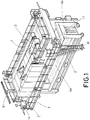
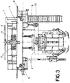
- Said automatic auxiliary crane comprises: A Main Structure (1), made up of two box girders and two headwalls joined thereto, as well as a grid floor, gangway and railing for supporting and maintaining equipment.
- a Longitudinal Translation System (2) made up of two motors and four wheels, that enable translation with respect to the electrolysis tanks of the installation, in a direction perpendicular to the longitudinal direction of the electrolysis rods on rails (8) abutting on rail beams (9)
- a Main Lifting System (3) mainly made up of a lifting geared motor and two drums.
- An Electrode Collection System (4) made up of A Load-bearing structure of the electrode collection trolley (4a) and a centering and guiding System (4b), centering the crane and guiding the load-bearing structure of the electrode collection trolley (4a).
- An Anti-Oscillation System A Contact Temperature Checking System
- An Electrode Voltage Checking System A Morphological Analysis System of the deposited metal
- An Auxiliary Lifting Mechanism A Feeding System (6) An Electrical Installation, a Control System and an Air Conditioning and Cabinet Pressurization System (7).
- the supports (9) and rails (8) of the main bridge corresponding to the bridge crane of the main crane can be used, thus minimizing the cost of the auxiliary bridge and thereby the operational costs of the maintenance method.
- the automatic auxiliary crane can accommodate auxiliary means for the operation thereof in order to carry out the method, such as a control unit or PLC for controlling the movements of the auxiliary bridge, electrical systems, refrigeration equipment and pressurization equipment.
- the automatic auxiliary bridge can also have access platforms for maintenance and supervision of said means. Access to these platforms from the transit areas of the electrolysis installation can be carried out by means of a ladder (10).
- the full extent of travel of the auxiliary crane is limited in one direction by the stops of the rails, while in the other direction it is limited by the proximity of the main crane.
- the drive of the wheels (11) of the headwalls for moving the auxiliary bridge can be carried out by means of an independent electric motor for each drive wheel that acts through an appropriate reducer and is commanded by means of a converter that makes it possible to use the appropriate translation and approximation speeds.
- the motors can also incorporate brakes, preferably electrically driven brakes.
- the displacement system of the described auxiliary bridge enables ensuring a positioning with respect to the electrolysis cells that is sufficiently precise to carry out the maintenance method according to the invention.
- position detectors can be used on the parts of the crane with respect to which they move, such as markings.
- the electrode collection system (4) comprises: A load-bearing structure of the electrode collection trolley (4a), and the centering and guiding system (4b). Both elements will have relative movements between them during the lifting and lowering strokes.
- the load-bearing structure of the electrode collection trolley (4a) which is in charge of handling the electrodes, comprises: A frame that supports both the electrode collection trolley (4c) itself and the guide frame when it is lifted.
- This Frame incorporates four guide elements at the ends thereof that will enable the relative vertical movement of the Electrode Collection Trolley along the guides that the Guiding Structure will be equipped with.
- the electrode collection trolley (4c) in charge of handling the electrodes consisting of a frame on four wheels, two of which are motorized, which has four sets of opening and closing mechanisms of the electrode collection lugs.
- the centering and guiding system (4b) is positioned on the upper part of the tank, ensuring the correct position of the Electrode Collection Trolley with respect to the electrodes for their handling.
- the load-bearing structure of the electrode collection trolley (4a) will be in charge of the vertical movements of the centering and guiding system (4b) when dragging it in the vertical movements thereof, when abutting with it.
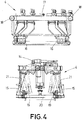
- the electrode collection trolley (4c), as shown in detail in Figure 4 is configured for managing the electrode units, comprising a frame (17) on four wheels (18), two of which are motorized, which has opening and closing means (14) of the tilting gripping arms (21) with electrode collection lugs (15). These lugs have a coupling hole (16) adapted to engage with the gripping means (19) provided in electrode heads (20) of the installation, thus enabling management and handling thereof.
- the tilting gripping arms (21) can be built with two rotating arms that support the collection lugs (15), for example, driven in a coordinated manner by a single linear actuator that make up the opening and closing means (14). The use of two types of collection lugs (15) is anticipated, some for anodes and others for cathodes.
- the electrode collection trolley (4c) can incorporate laser detectors, each corresponding to the position of a collection lug, which enable identifying the presence of the electrode in the support thereof on the electrolysis rod, identifying both the number of electrodes present and the correct polarity thereof.
- a suitable detector system can be incorporated.
- the different elements of the auxiliary crane must be adequately protected against acid mist corrosion, especially found in zinc electrolysis installations, for example, by means of specific acid-proof paint.
- the detection system for detecting faulty electrode units may include a detection system with an electrode temperature sensor system, an electrode voltage drop checking system, a system for analyzing the morphology of the metal deposited on the electrodes and/or a system for balancing or checking the weight of the electrodes.
- the temperature sensor system may include as many sensors as electrodes in the tank.
- the electrode voltage drop checking system includes voltage drop sensors, which can include as many voltage probes as the number of cathodes plus a probe, for measuring the voltage between the electrode rod and the electrolysis rail on which it abuts.
- the system for analyzing the morphology of the metal can comprise fixed cameras intended to take pictures of the surface of the metal deposited on the electrode. These pictures can be analyzed manually by an operator in order to assess possible faults in the deposition or automatically by means of image analysis systems. The pictures have sufficient resolution to enable a global analysis of the electrode and the processing thereof so that they can serve as a basis for comparative and statistical analyses.
- a control unit can be used programmed to detect information from the sensors on the state of the electrode units, process said information and command the auxiliary crane through displacements of the crane and the components thereof, such as translation of the automatic auxiliary crane, lifting and lowering of the electrode collection system, the auxiliary hoist, the electrode collection trolley or the electrode collection lugs.
- the control unit can also enable partially automatic or semi-automatic control, allowing one or several of the stages of the method to be carried out manually by an operator.
Landscapes
- Chemical & Material Sciences (AREA)
- Engineering & Computer Science (AREA)
- Chemical Kinetics & Catalysis (AREA)
- Electrochemistry (AREA)
- Materials Engineering (AREA)
- Metallurgy (AREA)
- Organic Chemistry (AREA)
- Mechanical Engineering (AREA)
- Electrolytic Production Of Metals (AREA)
- Electrolytic Production Of Non-Metals, Compounds, Apparatuses Therefor (AREA)
Claims (16)
- Wartungsmethode einer Elektrolyseanlage, die die folgenden Schritte umfasst:- Identifizierung von Anomalien in den Elektroden, die in den Behältern angeordnet sind, wie zum Beispiel einen Temperaturanstieg, anomale elektrische Kontakte und Fehler in der Morphologie des in den Elektroden abgeschiedenen Metalls mittels eines Detektionssystems mit mindestens einem Sensor;- Herausstrennen, Entfernen und Ersetzen der anomalen Elektroden, indem diese aus den Elektrolysebehältern der Einrichtung in den Reparatur- und Ersatzbereich gebracht werden; und- Repositionierung neuer Elektroden durch Einsetzen in ihre Betriebspositionen, dadurch gekennzeichnet, dass die Schritte des Heraustrennens, Entfernens, Ersetzens und der Repositionierung mittels eines Hilfskrans durchgeführt werden, der sich von dem Hauptkran unterscheidet, der für den Betrieb der Anlage verwendet wird, und wobei der mindestens eine Sensor in Bezug auf den Elektrolysetank statisch bleibt.
- Wartungsmethode einer Elektrolyseanlage nach Anspruch 1, dadurch gekennzeichnet, dass der Schritt des Erkennens von Anomalien in den Elektroden, des Heraustrennens, Entfernens und Ersetzens der Elektroden sowie des Repositionierens neuer Elektroden automatisch durchgeführt wird.
- Wartungsmethode einer Elektrolyseanlage nach einem der Ansprüche 1 oder 2, dadurch gekennzeichnet, dass der mindestens eine Sensor aus der Gruppe die aus einem Elektroden-Temperatursensor, einem Elektroden-Spannungsabfallsensor, einem System zur Analyse der Morphologie des auf den Elektroden abgeschiedenen Metalls, einem Elektroden-Gewichtssensor und einer Kombination der genannten, besteht, ausgewählt ist.
- Wartungsmethode einer Elektrolyseanlage nach Anspruch 3, dadurch gekennzeichnet, dass es die Verwendung einer Steuereinheit umfasst, die programmiert ist, um automatisch Informationen von dem Detektionssystem zu empfangen, diese Informationen verarbeiten und dem Hilfskran zu befehlen, die fehlerhafte Elektrodeneinheit zu versetzen oder zu entfernen und/oder die Ersatzelektrodeneinheit einzusetzen.
- Wartungsmethode einer Elektrolyseanlage nach Anspruch 4, dadurch gekennzeichnet, dass der Brückenkran des Hilfskrans zum Versetzen oder Entfernen der fehlerhaften Elektrodeneinheit und zum Einsetzen der Ersatzelektrodeneinheit in die Lücke ein Elektrodeneinheitensammelsystem mit einem Elektrodeneinheitensammelwagen umfasst.
- Elektrolyseanlage mit einem Hauptkran zum Betreiben der Anlage und einem automatischen Hilfskran zu deren Wartung, dadurch gekennzeichnet, dass der automatische Hilfskran Folgendes umfasst:- eine Hauptstruktur (1), die aus zwei Kastenträgern und zwei damit verbundenen Stirnwänden sowie einem Gitterboden, einem Laufsteg und einem Geländer zum Tragen und Warten von Ausrüstung besteht;- einem Längsverschiebungssystem (2), das aus zwei Motoren besteht, die auf Rädern angetrieben sind und eine Verschiebung in Bezug auf die Elektrolysebehälter der Anlage in einer Richtung senkrecht zur Längsrichtung der Elektrolyse-Stäbe auf Schienen (8) ermöglichen, die auf Schienenträgern (9) aufliegen;- ein Haupthubsystem (3), das im Wesentlichen aus einem Hubgetriebemotor und zwei Trommeln besteht; und- ein Elektrodensammelsystem (4), das eine lasttragende Struktur des Elektrodensammelwagens (4a) und ein Zentrier- und Führungssystem (4b) umfasst, wobei beide Elemente während der Hub- und Senkhübe Relativbewegungen zueinander aufweisen.
- Elektrolyseanlage nach Anspruch 6, dadurch gekennzeichnet, dass ein Elektrodensammelwagen (4c) die Elektrodeneinheiten handhabt und einen Rahmen (17) auf vier Rädern (18), von denen zwei motorisiert sind, umfasst, der Öffnungs- und Schließmitteln (14) eines kippbaren Greifarms (21) mit Elektrodensammellaschen (15) aufweist, wobei diese Laschen mit einem Kupplungsloch (16) versehen sind, das geeignet ist, in Greifmittel (19) einzugreifen, die in Elektrodenköpfen (20) der Anlage vorgesehen sind, wodurch deren Verwaltung und Handhabung ermöglicht wird.
- Elektrolyseanlage nach Anspruch 7, dadurch gekennzeichnet, dass die kippbaren Greifarme (21) mit zwei drehbaren Armen ausgeführt sind, die die Sammellaschen (15) tragen und die koordiniert von einem einzigen Linearantrieb angetrieben werden und die Öffnungs- und Schließmittel (14) bilden.
- Elektrolyseanlage nach einem der Ansprüche 6 bis 8, dadurch gekennzeichnet, dass zwei Arten von Sammellaschen (15) verwendet werden, eine für Anoden und die andere für Kathoden.
- Elektrolyseanlage nach einem der Ansprüche 6 bis 9, dadurch gekennzeichnet, dass das Vorhandensein einer Elektrode oder einer Lücke in dem Elektrolysebehälter mittels Laserdetektoren erkannt wird, die jeweils mit der Position einer Sammelasche korrespondieren und es ermöglichen, das Vorhandensein einer Elektrode in deren Halterung an dem Elektrolysestab zu erkennen, wobei sowohl die Anzahl der vorhandenen Elektroden als auch deren korrekte Polarität erkannt werden, wobei diese Elemente in dem Elektrodensammelwagen (4c) angeordnet sind.
- Elektrolyseanlage nach einem der Ansprüche 6 bis 10, dadurch gekennzeichnet, dass sie zur Steuerung des Absenkens des Elektrodensammelsystems (4) in Richtung der Elektrolysezelle ein Detektorsystem enthält, wobei sie ferner weitere Schutzvorrichtungen, wie z. B. Antischwingungsvorrichtungen, enthält, um ein Schwingen oder Bewegen, der Elektrodeneinheiten während der Hebe- und Senkbewegungen in Bezug auf den Sammelwagen zu verhindern.
- Elektrolyseanlage nach einem der Ansprüche 6 bis 11, dadurch gekennzeichnet, dass sie weiterhin Folgendes umfasst:- ein Erkennungssystem zum Erkennen fehlerhafter Elektrodeneinheiten mit einem Elektroden-Temperatursensorsystem,- ein Elektroden-Spannungsabfall-Kontrollsystem- ein System zum Analysieren des auf den Elektroden abgeschiedenen Metalls und/oder- ein System zum Ausgleichen oder Überprüfen des Gewichts der Elektroden.
- Elektrolyseanlage nach Anspruch 12, dadurch gekennzeichnet, dass das Temperatursensorsystem so viele Sensoren wie Elektroden im Elektrolysebehälter umfassen kann.
- Elektrolyseanlage nach Anspruch 12, dadurch gekennzeichnet, dass das Elektroden-Spannungsabfall-Kontrollsystem Spannungsabfallsensoren umfasst, die so viele Spannungssonden wie die Anzahl der Kathoden plus eine Sonde umfassen können, um die Spannung zwischen dem Elektrodenstab und der Elektrolyseschiene, an der er anliegt, zu messen.
- Elektrolyseanlage nach Anspruch 12, dadurch gekennzeichnet, dass das System zur Analyse des abgeschiedenen Metalls feststehende Kameras umfasst, die dazu bestimmt sind, Bilder von der Oberfläche des auf der Elektrode abgeschiedenen Metalls aufzunehmen, die manuell von einem Bediener oder automatisch mit Hilfe von Bildanalysesystemen analysiert werden, um mögliche Fehler in der Abscheidung zu beurteilen.
- Elektrolyseanlage nach einem der Ansprüche 6 bis 15, dadurch gekennzeichnet, dass sie eine Steuereinheit aufweist, die programmiert ist, um Informationen von Sensoren über den Zustand der Elektrodeneinheiten zu erfassen, diese Informationen zu verarbeiten und den Hilfskran durch Verschiebungen des Krans und jeder der Komponenten des Hilfskrans, wie zum Beispiels die Verschiebung des gesamten Krans, das Anheben des Elektrodensammelsystems (4), das aus der lasttragenden Struktur des Elektrodensammelwagens (4a), dem Zentrier- und Führungssystem (4b), dem Elektrodensammelwagen (4c) und einem Hilfshubmechanismus (5) besteht, zu steuern.
Applications Claiming Priority (1)
| Application Number | Priority Date | Filing Date | Title |
|---|---|---|---|
| PCT/ES2016/070126 WO2017144741A1 (es) | 2016-02-25 | 2016-02-25 | Grua auxiliar automática para mantenimiento de una instalación de electrolisis |
Publications (3)
| Publication Number | Publication Date |
|---|---|
| EP3460106A1 EP3460106A1 (de) | 2019-03-27 |
| EP3460106A4 EP3460106A4 (de) | 2020-04-15 |
| EP3460106B1 true EP3460106B1 (de) | 2021-06-23 |
Family
ID=59685901
Family Applications (1)
| Application Number | Title | Priority Date | Filing Date |
|---|---|---|---|
| EP16891325.9A Active EP3460106B1 (de) | 2016-02-25 | 2016-02-25 | Automatischer hilfskran zur aufrechterhaltung einer elektrolyseanlage |
Country Status (5)
| Country | Link |
|---|---|
| EP (1) | EP3460106B1 (de) |
| ES (1) | ES2890827T3 (de) |
| MX (1) | MX2017000943A (de) |
| RU (1) | RU2018133681A (de) |
| WO (1) | WO2017144741A1 (de) |
Families Citing this family (2)
| Publication number | Priority date | Publication date | Assignee | Title |
|---|---|---|---|---|
| CN113814650B (zh) * | 2021-09-23 | 2024-01-26 | 华能荆门热电有限责任公司 | 等离子阴阳极安装辅助装置及维护检修方法 |
| CN119530890B (zh) * | 2025-01-22 | 2025-04-25 | 包头铝业有限公司 | 一种铝电解槽ptm阳极自动换极装置与方法 |
Family Cites Families (6)
| Publication number | Priority date | Publication date | Assignee | Title |
|---|---|---|---|---|
| CH592164A5 (en) * | 1972-09-28 | 1977-10-14 | Zannini Gianfranco | Electrolytic plant for primary aluminium prodn. - is laid out above ground to separate productive from ancillary processes |
| JPS5296904A (en) * | 1976-02-10 | 1977-08-15 | Mitsui Mining & Smelting Co | Apparatus for automatic replacement of plate electrode in electrolysis of metals |
| FR2874934B1 (fr) * | 2004-09-08 | 2007-09-07 | Ecl Soc Par Actions Simplifiee | Procede de changement d'anode dans une cellule de production d'aluminium par electrolyse incluant un ajustement de la position de l'anode et dispositif pour le mettre en oeuvre |
| FI124617B (en) * | 2012-04-23 | 2014-11-14 | Outotec Oyj | transfer System |
| NO336059B1 (no) * | 2012-12-27 | 2015-05-04 | Sinvent As | Fremgangsmåte og apparat for rensing av karbonanoder |
| CN203845728U (zh) * | 2014-05-26 | 2014-09-24 | 广西百色银海铝业有限责任公司 | 电解槽上用于安装阴极的辅助装置 |
-
2016
- 2016-02-25 RU RU2018133681A patent/RU2018133681A/ru not_active Application Discontinuation
- 2016-02-25 EP EP16891325.9A patent/EP3460106B1/de active Active
- 2016-02-25 ES ES16891325T patent/ES2890827T3/es active Active
- 2016-02-25 WO PCT/ES2016/070126 patent/WO2017144741A1/es not_active Ceased
- 2016-02-25 MX MX2017000943A patent/MX2017000943A/es unknown
Non-Patent Citations (1)
| Title |
|---|
| None * |
Also Published As
| Publication number | Publication date |
|---|---|
| RU2018133681A (ru) | 2020-03-25 |
| EP3460106A4 (de) | 2020-04-15 |
| MX2017000943A (es) | 2018-02-09 |
| EP3460106A1 (de) | 2019-03-27 |
| RU2018133681A3 (de) | 2020-03-25 |
| ES2890827T3 (es) | 2022-01-24 |
| WO2017144741A1 (es) | 2017-08-31 |
Similar Documents
| Publication | Publication Date | Title |
|---|---|---|
| EP2794958B1 (de) | Elektroraffinierungssystem zur gewinnung von gereinigtem metall aus einem unreinen nuklearen rohmaterial | |
| CA2523656C (en) | Process and apparatus for positioning replacement anodes in electrolytic cells | |
| EP2031097B1 (de) | System zum Abstreifen von Kathoden | |
| US20070295601A1 (en) | Anode Support Apparatus | |
| EP3460106B1 (de) | Automatischer hilfskran zur aufrechterhaltung einer elektrolyseanlage | |
| ZA200604323B (en) | A method and equipment for positioning when replacing anodes in an electrolysis cell | |
| RU2382834C2 (ru) | Устройство манипулирования крышками электролизера для производства алюминия электролизом | |
| JP2002012996A (ja) | 電解製錬における異常電極の自動検出方法 | |
| RU2370574C2 (ru) | Компактный модуль обслуживания, предназначенный для применения на заводах по производству алюминия электролизом | |
| JP3925983B2 (ja) | 電解製錬の異常検出方法及びそれを実施する異常検出システム | |
| JP4884439B2 (ja) | 不良陰極板の排除装置及び不良陰極板の排除方法 | |
| CN114622251A (zh) | 一种电解生产中短路异常的处理方法和系统 | |
| RU2699600C2 (ru) | Система для выполнения операций, связанных с использованием электролизеров в установке для производства алюминия посредством электролиза | |
| JP3189947B2 (ja) | 電解製錬の異常検出方法及びそれを実施する異常検出システム | |
| JP3784614B2 (ja) | 陰極板自動搬送入替装置 | |
| RU2375502C2 (ru) | Способ замены анода в электролизере по производству алюминия электролизом, включающий регулирование положения анода, и устройство для его осуществления | |
| RU2704395C1 (ru) | Система для мониторинга анодов, применяемая в электролитическом процессе | |
| JPH0941182A (ja) | 電解槽内の異常電極検出装置 | |
| CN111424293B (zh) | 一种剥锌设备阴极板自动运载和放置装置及其运行方法 | |
| CN112210799B (zh) | 包括运输阴极板和阳极板的升降设备的电解沉积生产线 | |
| US20250376780A1 (en) | Anode servicing assembly for an aluminium electrolysis plant, and methods for operating the same | |
| JP2023039600A (ja) | カソード絶縁治具およびカソード絶縁方法 | |
| AU2006227546A1 (en) | Anode support apparatus |
Legal Events
| Date | Code | Title | Description |
|---|---|---|---|
| STAA | Information on the status of an ep patent application or granted ep patent |
Free format text: STATUS: THE INTERNATIONAL PUBLICATION HAS BEEN MADE |
|
| PUAI | Public reference made under article 153(3) epc to a published international application that has entered the european phase |
Free format text: ORIGINAL CODE: 0009012 |
|
| STAA | Information on the status of an ep patent application or granted ep patent |
Free format text: STATUS: REQUEST FOR EXAMINATION WAS MADE |
|
| 17P | Request for examination filed |
Effective date: 20181126 |
|
| AK | Designated contracting states |
Kind code of ref document: A1 Designated state(s): AL AT BE BG CH CY CZ DE DK EE ES FI FR GB GR HR HU IE IS IT LI LT LU LV MC MK MT NL NO PL PT RO RS SE SI SK SM TR |
|
| AX | Request for extension of the european patent |
Extension state: BA ME |
|
| DAV | Request for validation of the european patent (deleted) | ||
| DAX | Request for extension of the european patent (deleted) | ||
| REG | Reference to a national code |
Ref country code: DE Ref legal event code: R079 Ref document number: 602016059816 Country of ref document: DE Free format text: PREVIOUS MAIN CLASS: C25C0007000000 Ipc: C25C0001160000 |
|
| A4 | Supplementary search report drawn up and despatched |
Effective date: 20200317 |
|
| RIC1 | Information provided on ipc code assigned before grant |
Ipc: B66C 17/06 20060101ALI20200311BHEP Ipc: C25C 1/16 20060101AFI20200311BHEP Ipc: C25C 7/06 20060101ALI20200311BHEP |
|
| STAA | Information on the status of an ep patent application or granted ep patent |
Free format text: STATUS: EXAMINATION IS IN PROGRESS |
|
| 17Q | First examination report despatched |
Effective date: 20200916 |
|
| GRAP | Despatch of communication of intention to grant a patent |
Free format text: ORIGINAL CODE: EPIDOSNIGR1 |
|
| STAA | Information on the status of an ep patent application or granted ep patent |
Free format text: STATUS: GRANT OF PATENT IS INTENDED |
|
| INTG | Intention to grant announced |
Effective date: 20210309 |
|
| GRAS | Grant fee paid |
Free format text: ORIGINAL CODE: EPIDOSNIGR3 |
|
| GRAA | (expected) grant |
Free format text: ORIGINAL CODE: 0009210 |
|
| STAA | Information on the status of an ep patent application or granted ep patent |
Free format text: STATUS: THE PATENT HAS BEEN GRANTED |
|
| AK | Designated contracting states |
Kind code of ref document: B1 Designated state(s): AL AT BE BG CH CY CZ DE DK EE ES FI FR GB GR HR HU IE IS IT LI LT LU LV MC MK MT NL NO PL PT RO RS SE SI SK SM TR |
|
| REG | Reference to a national code |
Ref country code: GB Ref legal event code: FG4D |
|
| REG | Reference to a national code |
Ref country code: CH Ref legal event code: EP |
|
| REG | Reference to a national code |
Ref country code: DE Ref legal event code: R096 Ref document number: 602016059816 Country of ref document: DE Ref country code: AT Ref legal event code: REF Ref document number: 1404395 Country of ref document: AT Kind code of ref document: T Effective date: 20210715 |
|
| REG | Reference to a national code |
Ref country code: IE Ref legal event code: FG4D |
|
| REG | Reference to a national code |
Ref country code: LT Ref legal event code: MG9D |
|
| PG25 | Lapsed in a contracting state [announced via postgrant information from national office to epo] |
Ref country code: FI Free format text: LAPSE BECAUSE OF FAILURE TO SUBMIT A TRANSLATION OF THE DESCRIPTION OR TO PAY THE FEE WITHIN THE PRESCRIBED TIME-LIMIT Effective date: 20210623 Ref country code: LT Free format text: LAPSE BECAUSE OF FAILURE TO SUBMIT A TRANSLATION OF THE DESCRIPTION OR TO PAY THE FEE WITHIN THE PRESCRIBED TIME-LIMIT Effective date: 20210623 Ref country code: HR Free format text: LAPSE BECAUSE OF FAILURE TO SUBMIT A TRANSLATION OF THE DESCRIPTION OR TO PAY THE FEE WITHIN THE PRESCRIBED TIME-LIMIT Effective date: 20210623 Ref country code: BG Free format text: LAPSE BECAUSE OF FAILURE TO SUBMIT A TRANSLATION OF THE DESCRIPTION OR TO PAY THE FEE WITHIN THE PRESCRIBED TIME-LIMIT Effective date: 20210923 |
|
| REG | Reference to a national code |
Ref country code: CH Ref legal event code: PK Free format text: BERICHTIGUNGEN |
|
| REG | Reference to a national code |
Ref country code: AT Ref legal event code: MK05 Ref document number: 1404395 Country of ref document: AT Kind code of ref document: T Effective date: 20210623 |
|
| RAP2 | Party data changed (patent owner data changed or rights of a patent transferred) |
Owner name: ZINCOBRE INGENIERIA, S.L. |
|
| RIN2 | Information on inventor provided after grant (corrected) |
Inventor name: LEFEVRE, YVES |
|
| PG25 | Lapsed in a contracting state [announced via postgrant information from national office to epo] |
Ref country code: GR Free format text: LAPSE BECAUSE OF FAILURE TO SUBMIT A TRANSLATION OF THE DESCRIPTION OR TO PAY THE FEE WITHIN THE PRESCRIBED TIME-LIMIT Effective date: 20210924 Ref country code: LV Free format text: LAPSE BECAUSE OF FAILURE TO SUBMIT A TRANSLATION OF THE DESCRIPTION OR TO PAY THE FEE WITHIN THE PRESCRIBED TIME-LIMIT Effective date: 20210623 Ref country code: RS Free format text: LAPSE BECAUSE OF FAILURE TO SUBMIT A TRANSLATION OF THE DESCRIPTION OR TO PAY THE FEE WITHIN THE PRESCRIBED TIME-LIMIT Effective date: 20210623 Ref country code: SE Free format text: LAPSE BECAUSE OF FAILURE TO SUBMIT A TRANSLATION OF THE DESCRIPTION OR TO PAY THE FEE WITHIN THE PRESCRIBED TIME-LIMIT Effective date: 20210623 |
|
| REG | Reference to a national code |
Ref country code: NL Ref legal event code: MP Effective date: 20210623 |
|
| REG | Reference to a national code |
Ref country code: NO Ref legal event code: T2 Effective date: 20210623 |
|
| REG | Reference to a national code |
Ref country code: ES Ref legal event code: FG2A Ref document number: 2890827 Country of ref document: ES Kind code of ref document: T3 Effective date: 20220124 |
|
| PG25 | Lapsed in a contracting state [announced via postgrant information from national office to epo] |
Ref country code: SK Free format text: LAPSE BECAUSE OF FAILURE TO SUBMIT A TRANSLATION OF THE DESCRIPTION OR TO PAY THE FEE WITHIN THE PRESCRIBED TIME-LIMIT Effective date: 20210623 Ref country code: SM Free format text: LAPSE BECAUSE OF FAILURE TO SUBMIT A TRANSLATION OF THE DESCRIPTION OR TO PAY THE FEE WITHIN THE PRESCRIBED TIME-LIMIT Effective date: 20210623 Ref country code: PT Free format text: LAPSE BECAUSE OF FAILURE TO SUBMIT A TRANSLATION OF THE DESCRIPTION OR TO PAY THE FEE WITHIN THE PRESCRIBED TIME-LIMIT Effective date: 20211025 Ref country code: RO Free format text: LAPSE BECAUSE OF FAILURE TO SUBMIT A TRANSLATION OF THE DESCRIPTION OR TO PAY THE FEE WITHIN THE PRESCRIBED TIME-LIMIT Effective date: 20210623 Ref country code: NL Free format text: LAPSE BECAUSE OF FAILURE TO SUBMIT A TRANSLATION OF THE DESCRIPTION OR TO PAY THE FEE WITHIN THE PRESCRIBED TIME-LIMIT Effective date: 20210623 Ref country code: AT Free format text: LAPSE BECAUSE OF FAILURE TO SUBMIT A TRANSLATION OF THE DESCRIPTION OR TO PAY THE FEE WITHIN THE PRESCRIBED TIME-LIMIT Effective date: 20210623 Ref country code: CZ Free format text: LAPSE BECAUSE OF FAILURE TO SUBMIT A TRANSLATION OF THE DESCRIPTION OR TO PAY THE FEE WITHIN THE PRESCRIBED TIME-LIMIT Effective date: 20210623 Ref country code: EE Free format text: LAPSE BECAUSE OF FAILURE TO SUBMIT A TRANSLATION OF THE DESCRIPTION OR TO PAY THE FEE WITHIN THE PRESCRIBED TIME-LIMIT Effective date: 20210623 |
|
| PG25 | Lapsed in a contracting state [announced via postgrant information from national office to epo] |
Ref country code: PL Free format text: LAPSE BECAUSE OF FAILURE TO SUBMIT A TRANSLATION OF THE DESCRIPTION OR TO PAY THE FEE WITHIN THE PRESCRIBED TIME-LIMIT Effective date: 20210623 |
|
| REG | Reference to a national code |
Ref country code: DE Ref legal event code: R097 Ref document number: 602016059816 Country of ref document: DE |
|
| PG25 | Lapsed in a contracting state [announced via postgrant information from national office to epo] |
Ref country code: DK Free format text: LAPSE BECAUSE OF FAILURE TO SUBMIT A TRANSLATION OF THE DESCRIPTION OR TO PAY THE FEE WITHIN THE PRESCRIBED TIME-LIMIT Effective date: 20210623 |
|
| PLBE | No opposition filed within time limit |
Free format text: ORIGINAL CODE: 0009261 |
|
| STAA | Information on the status of an ep patent application or granted ep patent |
Free format text: STATUS: NO OPPOSITION FILED WITHIN TIME LIMIT |
|
| 26N | No opposition filed |
Effective date: 20220324 |
|
| PG25 | Lapsed in a contracting state [announced via postgrant information from national office to epo] |
Ref country code: AL Free format text: LAPSE BECAUSE OF FAILURE TO SUBMIT A TRANSLATION OF THE DESCRIPTION OR TO PAY THE FEE WITHIN THE PRESCRIBED TIME-LIMIT Effective date: 20210623 |
|
| PG25 | Lapsed in a contracting state [announced via postgrant information from national office to epo] |
Ref country code: IT Free format text: LAPSE BECAUSE OF FAILURE TO SUBMIT A TRANSLATION OF THE DESCRIPTION OR TO PAY THE FEE WITHIN THE PRESCRIBED TIME-LIMIT Effective date: 20210623 |
|
| REG | Reference to a national code |
Ref country code: DE Ref legal event code: R119 Ref document number: 602016059816 Country of ref document: DE |
|
| PG25 | Lapsed in a contracting state [announced via postgrant information from national office to epo] |
Ref country code: MC Free format text: LAPSE BECAUSE OF FAILURE TO SUBMIT A TRANSLATION OF THE DESCRIPTION OR TO PAY THE FEE WITHIN THE PRESCRIBED TIME-LIMIT Effective date: 20210623 |
|
| REG | Reference to a national code |
Ref country code: BE Ref legal event code: MM Effective date: 20220228 |
|
| GBPC | Gb: european patent ceased through non-payment of renewal fee |
Effective date: 20220225 |
|
| PG25 | Lapsed in a contracting state [announced via postgrant information from national office to epo] |
Ref country code: LU Free format text: LAPSE BECAUSE OF NON-PAYMENT OF DUE FEES Effective date: 20220225 |
|
| PG25 | Lapsed in a contracting state [announced via postgrant information from national office to epo] |
Ref country code: FR Free format text: LAPSE BECAUSE OF NON-PAYMENT OF DUE FEES Effective date: 20220228 |
|
| PG25 | Lapsed in a contracting state [announced via postgrant information from national office to epo] |
Ref country code: IE Free format text: LAPSE BECAUSE OF NON-PAYMENT OF DUE FEES Effective date: 20220225 Ref country code: GB Free format text: LAPSE BECAUSE OF NON-PAYMENT OF DUE FEES Effective date: 20220225 Ref country code: DE Free format text: LAPSE BECAUSE OF NON-PAYMENT OF DUE FEES Effective date: 20220901 |
|
| PG25 | Lapsed in a contracting state [announced via postgrant information from national office to epo] |
Ref country code: BE Free format text: LAPSE BECAUSE OF NON-PAYMENT OF DUE FEES Effective date: 20220228 |
|
| PG25 | Lapsed in a contracting state [announced via postgrant information from national office to epo] |
Ref country code: HU Free format text: LAPSE BECAUSE OF FAILURE TO SUBMIT A TRANSLATION OF THE DESCRIPTION OR TO PAY THE FEE WITHIN THE PRESCRIBED TIME-LIMIT; INVALID AB INITIO Effective date: 20160225 |
|
| PG25 | Lapsed in a contracting state [announced via postgrant information from national office to epo] |
Ref country code: MK Free format text: LAPSE BECAUSE OF FAILURE TO SUBMIT A TRANSLATION OF THE DESCRIPTION OR TO PAY THE FEE WITHIN THE PRESCRIBED TIME-LIMIT Effective date: 20210623 Ref country code: CY Free format text: LAPSE BECAUSE OF FAILURE TO SUBMIT A TRANSLATION OF THE DESCRIPTION OR TO PAY THE FEE WITHIN THE PRESCRIBED TIME-LIMIT Effective date: 20210623 |
|
| PG25 | Lapsed in a contracting state [announced via postgrant information from national office to epo] |
Ref country code: TR Free format text: LAPSE BECAUSE OF FAILURE TO SUBMIT A TRANSLATION OF THE DESCRIPTION OR TO PAY THE FEE WITHIN THE PRESCRIBED TIME-LIMIT Effective date: 20210623 |
|
| PG25 | Lapsed in a contracting state [announced via postgrant information from national office to epo] |
Ref country code: MT Free format text: LAPSE BECAUSE OF FAILURE TO SUBMIT A TRANSLATION OF THE DESCRIPTION OR TO PAY THE FEE WITHIN THE PRESCRIBED TIME-LIMIT Effective date: 20210623 |
|
| REG | Reference to a national code |
Ref country code: CH Ref legal event code: U11 Free format text: ST27 STATUS EVENT CODE: U-0-0-U10-U11 (AS PROVIDED BY THE NATIONAL OFFICE) Effective date: 20260301 |
|
| PGFP | Annual fee paid to national office [announced via postgrant information from national office to epo] |
Ref country code: ES Payment date: 20260303 Year of fee payment: 11 |
|
| PGFP | Annual fee paid to national office [announced via postgrant information from national office to epo] |
Ref country code: NO Payment date: 20260119 Year of fee payment: 11 |
|
| PGFP | Annual fee paid to national office [announced via postgrant information from national office to epo] |
Ref country code: CH Payment date: 20260301 Year of fee payment: 11 |