EP3459902B1 - Hydraulic circuit for variable displacement motor - Google Patents
Hydraulic circuit for variable displacement motor Download PDFInfo
- Publication number
- EP3459902B1 EP3459902B1 EP18186259.0A EP18186259A EP3459902B1 EP 3459902 B1 EP3459902 B1 EP 3459902B1 EP 18186259 A EP18186259 A EP 18186259A EP 3459902 B1 EP3459902 B1 EP 3459902B1
- Authority
- EP
- European Patent Office
- Prior art keywords
- conduit
- valve
- motor
- cubic capacity
- actuator
- Prior art date
- Legal status (The legal status is an assumption and is not a legal conclusion. Google has not performed a legal analysis and makes no representation as to the accuracy of the status listed.)
- Active
Links
Images

Classifications
-
- B—PERFORMING OPERATIONS; TRANSPORTING
- B66—HOISTING; LIFTING; HAULING
- B66D—CAPSTANS; WINCHES; TACKLES, e.g. PULLEY BLOCKS; HOISTS
- B66D1/00—Rope, cable, or chain winding mechanisms; Capstans
- B66D1/28—Other constructional details
- B66D1/40—Control devices
- B66D1/48—Control devices automatic
-
- F—MECHANICAL ENGINEERING; LIGHTING; HEATING; WEAPONS; BLASTING
- F03—MACHINES OR ENGINES FOR LIQUIDS; WIND, SPRING, OR WEIGHT MOTORS; PRODUCING MECHANICAL POWER OR A REACTIVE PROPULSIVE THRUST, NOT OTHERWISE PROVIDED FOR
- F03C—POSITIVE-DISPLACEMENT ENGINES DRIVEN BY LIQUIDS
- F03C1/00—Reciprocating-piston liquid engines
- F03C1/003—Reciprocating-piston liquid engines controlling
- F03C1/005—Reciprocating-piston liquid engines controlling motor piston stroke control
-
- B—PERFORMING OPERATIONS; TRANSPORTING
- B66—HOISTING; LIFTING; HAULING
- B66D—CAPSTANS; WINCHES; TACKLES, e.g. PULLEY BLOCKS; HOISTS
- B66D1/00—Rope, cable, or chain winding mechanisms; Capstans
- B66D1/02—Driving gear
- B66D1/08—Driving gear incorporating fluid motors
-
- B—PERFORMING OPERATIONS; TRANSPORTING
- B66—HOISTING; LIFTING; HAULING
- B66D—CAPSTANS; WINCHES; TACKLES, e.g. PULLEY BLOCKS; HOISTS
- B66D1/00—Rope, cable, or chain winding mechanisms; Capstans
- B66D1/28—Other constructional details
- B66D1/40—Control devices
- B66D1/42—Control devices non-automatic
- B66D1/44—Control devices non-automatic pneumatic of hydraulic
-
- B—PERFORMING OPERATIONS; TRANSPORTING
- B66—HOISTING; LIFTING; HAULING
- B66D—CAPSTANS; WINCHES; TACKLES, e.g. PULLEY BLOCKS; HOISTS
- B66D1/00—Rope, cable, or chain winding mechanisms; Capstans
- B66D1/54—Safety gear
- B66D1/56—Adaptations of limit switches
-
- F—MECHANICAL ENGINEERING; LIGHTING; HEATING; WEAPONS; BLASTING
- F03—MACHINES OR ENGINES FOR LIQUIDS; WIND, SPRING, OR WEIGHT MOTORS; PRODUCING MECHANICAL POWER OR A REACTIVE PROPULSIVE THRUST, NOT OTHERWISE PROVIDED FOR
- F03C—POSITIVE-DISPLACEMENT ENGINES DRIVEN BY LIQUIDS
- F03C1/00—Reciprocating-piston liquid engines
-
- F—MECHANICAL ENGINEERING; LIGHTING; HEATING; WEAPONS; BLASTING
- F03—MACHINES OR ENGINES FOR LIQUIDS; WIND, SPRING, OR WEIGHT MOTORS; PRODUCING MECHANICAL POWER OR A REACTIVE PROPULSIVE THRUST, NOT OTHERWISE PROVIDED FOR
- F03C—POSITIVE-DISPLACEMENT ENGINES DRIVEN BY LIQUIDS
- F03C2/00—Rotary-piston engines
-
- F—MECHANICAL ENGINEERING; LIGHTING; HEATING; WEAPONS; BLASTING
- F16—ENGINEERING ELEMENTS AND UNITS; GENERAL MEASURES FOR PRODUCING AND MAINTAINING EFFECTIVE FUNCTIONING OF MACHINES OR INSTALLATIONS; THERMAL INSULATION IN GENERAL
- F16H—GEARING
- F16H61/00—Control functions within control units of change-speed- or reversing-gearings for conveying rotary motion ; Control of exclusively fluid gearing, friction gearing, gearings with endless flexible members or other particular types of gearing
- F16H61/38—Control of exclusively fluid gearing
- F16H61/40—Control of exclusively fluid gearing hydrostatic
- F16H61/42—Control of exclusively fluid gearing hydrostatic involving adjustment of a pump or motor with adjustable output or capacity
- F16H61/423—Motor capacity control by fluid pressure control means
-
- B—PERFORMING OPERATIONS; TRANSPORTING
- B66—HOISTING; LIFTING; HAULING
- B66D—CAPSTANS; WINCHES; TACKLES, e.g. PULLEY BLOCKS; HOISTS
- B66D2700/00—Capstans, winches or hoists
- B66D2700/03—Mechanisms with latches or braking devices in general for capstans, hoists or similar devices as well as braking devices actuated electrically or by fluid under pressure
- B66D2700/035—Fluid operated braking devices
Definitions
- the present invention relates to a device for supplying and modifying a cylinder cubic capacity of a hydraulic motor.
- An example of the use of a hydraulic motor with a variable cubic capacity is the activation of a winch for lifting or pulling a load.
- the cubic capacity of the motor can be reduced and the rotation speed increased, thus increasing the rotation speed of the winch.
- the cubic capacity so as to have greater torque.
- Motors with variable cubic capacity currently available are activated and controlled through devices that comprise a first conduit, for supplying and discharging an operating fluid to a side of the hydraulic motor, and a second conduit, for supplying and discharging the operating fluid to the opposite side of the motor.
- the supply to the first or to the second conduit activates the motor in one rotation direction or in the opposite direction.
- An actuator is provided for modifying a cubic capacity of the motor.
- Such an actuator is normally of the oil dynamic type, e.g. a piston.
- An increase conduit for increasing the cubic capacity of the motor is connected to the actuator for supplying operating fluid to a side of the actuator which produces an increase of the cubic capacity of the motor.
- a reduction conduit for reducing the cubic capacity of the motor is connected to the actuator for supplying operating fluid to the opposite side of the actuator, which produces a reduction of the cubic capacity of the motor.
- the cubic capacity modification of the motor can therefore be commanded by supplying the increase conduit or the reduction conduit with the operating fluid.
- the cubic capacity increase or reduction command is sent manually by an operator.
- the operator adjusts the cubic capacity of the motor in relation to the load to be moved. This implies that often the motor does not work under the best possible conditions, as the assessment of the load by the operator cannot be absolutely precise, with the exception of some limit situations, e.g. movement without a load, for which the minimum cubic capacity is used in order to have the maximum rotation speed, or movement with maximum load, for which the maximum cubic capacity is used.
- Document US 6 371 447 B1 discloses a device for supplying and modifying a cylinder cubic capacity of a hydraulic motor according to the preamble of claim 1.
- the aim of the present invention is to offer a device for supplying and modifying the cubic capacity of a hydraulic motor that makes it possible to overcome the limits of currently available devices.
- the main advantage of the device according to the present invention is that it allows the automatic adjustment of the cubic capacity of the motor, i.e. without requiring the intervention of an operator, based on the size of the load to which the motor is subjected.
- the device according to the present invention is used for supplying and modifying the cubic capacity of a hydraulic motor (M) of the rotary or piston type, with a variable cubic capacity.
- M hydraulic motor
- the device could however be used for motors of another type.
- the motor (M), in turn, may be used for commanding a lifting winch (W).
- the winch (W) comprises at least one winding drum onto which a rope is wound. The drum can rotate in the two rotation directions for winding and unwinding a rope between a maximum winding condition and a maximum unwinding condition.
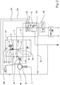
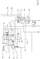
- the device according to the present invention comprises a first conduit (1), for supplying and discharging an operating fluid to a first side of the motor (M), and a second conduit (2) for supplying and discharging an operating fluid to a second side of the hydraulic motor (M).
- the supply of operating fluid to the first side of the motor (M), through the first conduit (1) produces the rotation in one direction of the motor (M), e.g. a rotation that produces the winding of the winch and the pulling of the load associated therewith.
- the operating fluid is discharged through the second side of the motor (M) and through the second conduit (2).
- the supply of operating fluid to the second side of the motor (M), through the second conduit (2) produces the rotation of the motor (M) in the opposite direction, e.g. a rotation that produces the unwinding of the winch and the release of the load associated therewith.
- a distributor is connected to the first conduit (1) and to the second conduit (2) for adjusting by command the supply and discharge of the operating fluid coming from one pump to one or another of the conduits (1,2), in a known way in the sector.
- the distributor is known in the sector and will therefore not be described in further detail.
- the device according to the present invention further comprises an actuator (3), provided to modify the cubic capacity of the motor (M).
- the actuator (3) is mechanically connected to a movable part of the motor (M) which, by moving, modifies the cubic capacity of the motor (M).
- Various types of actuators (3) and motors (M) with variable cubic capacity are known to a person skilled in the art and therefore will not be described in further detail, since the device according to the present invention can be used in any case.
- An increase conduit (31) for increasing the cubic capacity of the motor (M) is connected to the actuator (3).
- Such increase conduit (31) is provided for supplying operating fluid to a side of the actuator (3) which produces an increase of the cubic capacity of the motor (M).
- the actuator (3) is in the form of a cylinder, and the increase conduit (31) is connected to the shaft side of the actuator (3).
- a reduction conduit (32) for reducing the cubic capacity of the motor (M) is also connected to the actuator (3).
- Such reduction conduit is provided for supplying operating fluid to the opposite side of the actuator (3) which produces a reduction of the cubic capacity of the motor (M).
- the reduction conduit (32) is connected to the bottom side of the actuator (3).
- the device according to the present invention comprises a first piloting conduit (41), connected to a bistable valve (5) which is connected at the inlet to the first conduit (1) and to the second conduit (2).
- the first piloting conduit (41) is connected to the outlet of the bistable valve (5).
- the bistable valve (5) is provided with a floating element able to move between the outlet openings of the first conduit (1) and of the second conduit (2) due to the effect of the thrust produced by the operating fluid.
- the floating element In the event that the supply of operating fluid takes place through the first conduit (1), the floating element is pushed towards the outlet of the second conduit (2), causing the closure thereof.
- the piloting conduit (41) is supplied with the operating fluid.
- the first piloting conduit (41) is connected, at the outlet, to a first valve (6), whose characteristics and function will be described below.
- the device according to the present invention comprises a third conduit (11), connected at the inlet to the first conduit (1) and at the outlet to a union (12).
- the third conduit (11) is provided with a non-return valve that only allows the flow from the first conduit (1) towards the union (12).
- a fourth conduit (21) is also connected at the inlet to the second conduit (2) and at the outlet to the union (12).
- the fourth conduit (21) is provided with a non-return valve that only allows the flow from the second conduit (2) to the union (12).
- the union (12) is connected to the increase conduit (31); for producing, under certain conditions, the increase of cubic capacity of the motor (M).
- the operating fluid coming from the first conduit (1) or from the second conduit (2), through the union (12) is supplied to the increase conduit (31) and causes the displacement of the actuator (3) which commands the increase of cubic capacity of the motor (M).
- the device according to the present invention comprises a first valve (6) and a second valve (7), connected to each other through a channel (C).
- the first valve (6) can take a first operating position, in which it sets the union (12) in communication with the second valve (7) ( figures 1 and 2 ), and a second operating position, in which it occludes the union (12) ( figure 3 ).
- the first piloting conduit (41) is connected to the first valve (6) so as to displace it from the second position towards the first position.
- the first valve (6) is provided with a movable shutter, with three ways and two positions, which is piloted from the second position towards the first position by the pressure exerted by the operating fluid present in the first piloting conduit (41).
- An elastic means e.g. a spring, pushes the first valve (6) from the first position towards the second position.
- the elastic means or spring can be calibrated, i.e.
- the second valve (7) can take a first operating position, in which it occludes the union (12) ( figure 1 ), or it occludes the channel (C), and a second operating position ( figure 2 ), in which it sets the union (12) in communication with the reduction conduit (32).
- the second operating position of the second valve (7) the operating fluid, coming from the union (12), is supplied to the reduction conduit (32), passing through the first valve (6), the channel (C) and the second valve (7).
- a second piloting conduit (42) is connected to the union (12) and to the second valve (7) so as to displace the second valve from the second operating position to the first operating position.
- the second valve (7) is provided with a movable shutter, with three ways and two positions, which is piloted from the second position towards the first position by the pressure exerted by the operating fluid present in the second piloting conduit (42).
- An elastic means e.g. a spring, pushes the second valve (7) from the first position towards the second position.
- the elastic means or spring can be calibrated, i.e. it is possible to adjust the thrust exerted to a desired calibration value.
- the calibration value of the second valve (7) is greater than the calibration value of the first valve (6), as the second valve (7) has to move into its first operating position due to a greater pressure with respect to the pressure that activates the first valve (6).
- the operation of the device is as follows.
- the one shown in figure 3 can be considered, which illustrates the device in the absence of any command.
- the pressurised fluid is transmitted to the first conduit (1).
- the bistable valve (5) sets the first conduit (1) in communication with the first piloting conduit (41) which in turn receives the pressurised fluid. Due to the effect of the pressure in the first piloting conduit (41), the first valve (6) moves into its first operating position ( figure 1 ).
- the operating fluid, through the third conduit (11), is also supplied to the union (12) and to the second piloting conduit (42).
- the pressure inside the first conduit (1) is also high, just like the pressure inside the second piloting conduit (42), apart from any throttling or pressure reductions.
- the second valve (7) is brought into the first operating position ( figure 1 ), occluding the channel (C) and the union (12).
- the operating fluid present in the third conduit (11) is supplied to the increase conduit (31) of the actuator (3), which therefore causes an increase of the cubic capacity of the motor (M).
- the fluid present in the actuator (3) at the cubic capacity reduction side is discharged through the reduction conduit (32).
- the second valve (7) in the first position sets the reduction conduit (32) in connection with a discharge conduit.
- the pressure in the second piloting conduit (42) is also reduced. If the pressure in the second piloting conduit (42) drops below the calibration value of the second valve (7), the latter is brought into the second operating position, illustrated in figure 2 , in which it sets the union (12) in communication with the reduction conduit (32), through the first valve (6) and the channel (C). In such conditions the operating fluid is supplied to the reduction side of the actuator (3), so as to cause a reduction of the cubic capacity of the motor (M).
- Figures 1 and 2 show respectively a maximum load and maximum cubic capacity condition of the motor (M) and a minimum load and minimum cubic capacity condition of the motor (M).
- the first and the second valve (6,7) comprise proportional shutters, i.e. shutters that let through a flow rate of oil proportional to the displacement reached from the closed position. This makes the adjustment of the cubic capacity continuous for all the intermediate load values. Furthermore, the adjustment of the cubic capacity is gradual, to prevent any jolts to the load even in the presence of pressure peaks.
- the cubic capacity is preferable maximum, particularly for safety reasons.
- the motor (M) is at maximum cubic capacity and the winch (W) starts to be supplied with a load hanging, it is substantially certain that the winch will be able to support it.
- the winch is activated with the maximum load hanging starting from a minimum cubic capacity, the load would descend in a dangerous manner during the transition towards the maximum cubic capacity.
- the bistable valve (5) is connected to the first piloting conduit (41) through a conduit (51) which, advantageously, can be used to send the pressurised fluid to a safety brake (B) that acts on the winch (W).
- the brake (B) is activated by an actuator (L) which, through an elastic means, keeps the brake in the closed and locked position of the winch.
- the actuator (L) is activated in the open position of the brake (B) by means of the operating fluid coming from the first conduit (1) or from the second conduit (2) through the bistable valve (5).
- the conduit (51) connecting the bistable valve (5) to the first piloting conduit (41) is provided with a pressure reduction valve (52), so as to adjust the pressure to a desired value.
- the first conduit (1) may be provided with a load balancing and support valve (15).
- a load balancing and support valve (15) allows the free passage of fluid, through a one-directional passage, towards the motor (M), and in particular towards the first side or the winding side of the motor (M), which causes the winding of the winch (W).
- the balancing valve (15) remains closed, contributing to preventing the unwinding of the winch (W) due to the effect of the load.
- the balancing valve (15) is piloted to open by the operating fluid supplied to the second conduit (2).
- the device according to the present invention may also be provided with two limit switches (91,92). Both the switches comprise a two-way and two-position valve, held in the open position by an elastic means. Such valve is also connected to a mechanical element that is activated when the winch (W) nears a limit position.
- a first switch (91) is located along the first conduit (1) and is activated to close when the winch (W) nears the maximum winding position.
- a second switch (92) is located along the second conduit (2) and is activated to close when the winch (W) nears the maximum unwinding position.
- the second switch (92) is connected to the second conduit (2) through a first line (2a).
- a second line (2b) connects the second switch to the bistable valve (5).
Landscapes
- Engineering & Computer Science (AREA)
- Mechanical Engineering (AREA)
- General Engineering & Computer Science (AREA)
- Chemical & Material Sciences (AREA)
- Combustion & Propulsion (AREA)
- Physics & Mathematics (AREA)
- Fluid Mechanics (AREA)
- Fluid-Pressure Circuits (AREA)
Priority Applications (5)
| Application Number | Priority Date | Filing Date | Title |
|---|---|---|---|
| PL18186259T PL3459902T3 (pl) | 2017-09-25 | 2018-07-30 | Obwód hydrauliczny dla silnika o zmiennej wydajności |
| SM20200459T SMT202000459T1 (it) | 2017-09-25 | 2018-07-30 | Dispositivo per l'alimentazione e per la variazione di cilindrata di un motore idraulico |
| RS20200879A RS60619B1 (sr) | 2017-09-25 | 2018-07-30 | Hirdraulično kolo za motor sa varijabilnom radnom zapreminom |
| SI201830088T SI3459902T1 (sl) | 2017-09-25 | 2018-07-30 | Hidravlično vezje za variabilni motor |
| HRP20201145TT HRP20201145T1 (hr) | 2017-09-25 | 2020-07-22 | Hirdraulični strujni krug za motor sa varijabilnom radnom zapreminom |
Applications Claiming Priority (1)
| Application Number | Priority Date | Filing Date | Title |
|---|---|---|---|
| IT102017000106781A IT201700106781A1 (it) | 2017-09-25 | 2017-09-25 | Dispositivo per l’alimentazione e per la variazione di cilindrata di un motore idraulico. |
Publications (2)
| Publication Number | Publication Date |
|---|---|
| EP3459902A1 EP3459902A1 (en) | 2019-03-27 |
| EP3459902B1 true EP3459902B1 (en) | 2020-06-03 |
Family
ID=61024889
Family Applications (1)
| Application Number | Title | Priority Date | Filing Date |
|---|---|---|---|
| EP18186259.0A Active EP3459902B1 (en) | 2017-09-25 | 2018-07-30 | Hydraulic circuit for variable displacement motor |
Country Status (15)
| Country | Link |
|---|---|
| US (1) | US10865765B2 (it) |
| EP (1) | EP3459902B1 (it) |
| CN (1) | CN109555638B (it) |
| AU (1) | AU2019202041B2 (it) |
| DK (1) | DK3459902T3 (it) |
| ES (1) | ES2809744T3 (it) |
| HR (1) | HRP20201145T1 (it) |
| HU (1) | HUE049850T2 (it) |
| IT (1) | IT201700106781A1 (it) |
| PL (1) | PL3459902T3 (it) |
| PT (1) | PT3459902T (it) |
| RS (1) | RS60619B1 (it) |
| RU (1) | RU2746821C2 (it) |
| SI (1) | SI3459902T1 (it) |
| SM (1) | SMT202000459T1 (it) |
Families Citing this family (16)
| Publication number | Priority date | Publication date | Assignee | Title |
|---|---|---|---|---|
| CN112112867B (zh) * | 2020-08-25 | 2022-03-29 | 中联重科股份有限公司 | 液控式排气阀单元、液控排气式卷扬控制系统和卷扬机 |
| USD1013586S1 (en) | 2021-04-02 | 2024-02-06 | Manitou Italia S.R.L. | Protective grille for vehicle |
| CA206853S (en) | 2021-04-02 | 2023-07-20 | Manitou Italia Srl | Telescopic handler |
| USD982043S1 (en) | 2021-04-02 | 2023-03-28 | Manitou Italia S.R.L. | Ballast |
| USD1020812S1 (en) | 2021-11-18 | 2024-04-02 | Manitou Italia S.R.L. | Cabin for telescopic lifter |
| USD998835S1 (en) | 2021-11-18 | 2023-09-12 | Manitou Italia S.R.L. | Headlight for telescopic lifter |
| USD1005637S1 (en) | 2021-11-18 | 2023-11-21 | Manitou Italia S.R.L. | Turret for telescopic lifter |
| USD1060439S1 (en) | 2021-11-19 | 2025-02-04 | Manitou Italia S.R.L. | Console with hand controls for telescopic lifter |
| USD1048115S1 (en) | 2021-11-19 | 2024-10-22 | Manitou Italia S.R.L. | Cabin hood for a vehicle with a telescopic lifter |
| USD1026047S1 (en) | 2021-11-19 | 2024-05-07 | Manitou Italia S.R.L. | Visor for telescopic lifter |
| USD1070223S1 (en) | 2021-12-29 | 2025-04-08 | Manitou Italia S.R.L. | Part of cabin for telescopic lifter |
| USD1063289S1 (en) | 2021-12-29 | 2025-02-18 | Manitou Italia S.R.L. | Ladder for telescopic lifter |
| USD1103224S1 (en) | 2022-02-02 | 2025-11-25 | Manitou Italia S.R.L. | Handles for telescopic lifter |
| USD1086632S1 (en) | 2022-02-08 | 2025-07-29 | Manitou Italia S.R.L. | Cabin hood for a vehicle with a telescopic lifter |
| USD1060923S1 (en) | 2022-02-08 | 2025-02-04 | Manitou Italia S.R.L. | Platform for telescopic lifter |
| USD995578S1 (en) | 2022-02-08 | 2023-08-15 | Manitou Italia S.R.L. | Cabin for telescopic lifter |
Family Cites Families (15)
| Publication number | Priority date | Publication date | Assignee | Title |
|---|---|---|---|---|
| JPS57107666U (it) * | 1980-12-24 | 1982-07-02 | ||
| JPS61248899A (ja) * | 1985-04-23 | 1986-11-06 | 石川島播磨重工業株式会社 | 油圧駆動装置の巻上下速度制御装置 |
| JPS6283996A (ja) * | 1985-10-07 | 1987-04-17 | 川崎重工業株式会社 | 定馬力形液圧ウインチ制御装置 |
| SU1763350A1 (ru) * | 1990-04-02 | 1992-09-23 | Институт проблем надежности и долговечности машин АН БССР | Гидравлический привод лебедки |
| JP3508662B2 (ja) * | 1998-12-25 | 2004-03-22 | コベルコ建機株式会社 | 油圧駆動ウィンチの制御方法および同装置 |
| DE19913275A1 (de) * | 1999-03-24 | 2000-09-28 | Mannesmann Rexroth Ag | Hydraulische Steueranordnung zum Betreiben einer Winde im Fieren-, Hieven- und Mooring-Betrieb |
| JP3893857B2 (ja) * | 1999-11-25 | 2007-03-14 | コベルコクレーン株式会社 | 油圧駆動ウインチの制御装置 |
| EP1172325A3 (en) * | 2000-07-13 | 2002-04-17 | Kobelco Construction Machinery Co., Ltd. | Control device for hydraulic drive winch |
| DE10219849B4 (de) * | 2002-05-03 | 2004-03-25 | Brueninghaus Hydromatik Gmbh | Hydromotoreinheit |
| JP4208179B2 (ja) * | 2002-10-28 | 2009-01-14 | 株式会社小松製作所 | 油圧駆動車両 |
| JP5188444B2 (ja) * | 2009-04-23 | 2013-04-24 | カヤバ工業株式会社 | 作業機の液圧駆動装置 |
| JP5863561B2 (ja) * | 2012-05-15 | 2016-02-16 | 日立住友重機械建機クレーン株式会社 | 油圧ウインチの制御装置 |
| CN204125086U (zh) * | 2014-08-07 | 2015-01-28 | 辽宁瑞丰专用车制造有限公司 | 一种新式卷扬液压系统 |
| CN104632746B (zh) * | 2015-03-04 | 2017-11-24 | 徐州重型机械有限公司 | 切换阀、切换液压系统以及起重机 |
| DE102017200244A1 (de) * | 2017-01-10 | 2018-07-12 | Robert Bosch Gmbh | Hydrostatischer Axialkolbenmotor in Schrägachsenbauweise |
-
2017
- 2017-09-25 IT IT102017000106781A patent/IT201700106781A1/it unknown
-
2018
- 2018-07-30 SI SI201830088T patent/SI3459902T1/sl unknown
- 2018-07-30 DK DK18186259.0T patent/DK3459902T3/da active
- 2018-07-30 RS RS20200879A patent/RS60619B1/sr unknown
- 2018-07-30 PT PT181862590T patent/PT3459902T/pt unknown
- 2018-07-30 ES ES18186259T patent/ES2809744T3/es active Active
- 2018-07-30 HU HUE18186259A patent/HUE049850T2/hu unknown
- 2018-07-30 EP EP18186259.0A patent/EP3459902B1/en active Active
- 2018-07-30 SM SM20200459T patent/SMT202000459T1/it unknown
- 2018-07-30 PL PL18186259T patent/PL3459902T3/pl unknown
- 2018-08-01 US US16/051,963 patent/US10865765B2/en active Active
- 2018-08-29 CN CN201810994188.4A patent/CN109555638B/zh active Active
- 2018-09-24 RU RU2018133656A patent/RU2746821C2/ru active
-
2019
- 2019-03-25 AU AU2019202041A patent/AU2019202041B2/en active Active
-
2020
- 2020-07-22 HR HRP20201145TT patent/HRP20201145T1/hr unknown
Non-Patent Citations (1)
| Title |
|---|
| None * |
Also Published As
| Publication number | Publication date |
|---|---|
| CN109555638B (zh) | 2022-03-29 |
| HUE049850T2 (hu) | 2020-10-28 |
| EP3459902A1 (en) | 2019-03-27 |
| PL3459902T3 (pl) | 2020-11-02 |
| SI3459902T1 (sl) | 2020-08-31 |
| US10865765B2 (en) | 2020-12-15 |
| AU2019202041B2 (en) | 2024-03-21 |
| SMT202000459T1 (it) | 2020-11-10 |
| ES2809744T3 (es) | 2021-03-05 |
| US20190093625A1 (en) | 2019-03-28 |
| HRP20201145T1 (hr) | 2020-10-30 |
| CN109555638A (zh) | 2019-04-02 |
| RS60619B1 (sr) | 2020-09-30 |
| PT3459902T (pt) | 2020-07-31 |
| AU2019202041A1 (en) | 2019-04-18 |
| RU2018133656A3 (it) | 2020-07-13 |
| DK3459902T3 (da) | 2020-07-27 |
| RU2746821C2 (ru) | 2021-04-21 |
| RU2018133656A (ru) | 2020-03-25 |
| IT201700106781A1 (it) | 2019-03-25 |
Similar Documents
| Publication | Publication Date | Title |
|---|---|---|
| EP3459902B1 (en) | Hydraulic circuit for variable displacement motor | |
| US10859100B2 (en) | Hydraulic drive with fast stroke and load stroke | |
| CN111608999B (zh) | 致动器的流量控制 | |
| WO2017171021A1 (ja) | 油圧システム及び非常操作方法 | |
| JP7408897B2 (ja) | リフトトラックアタッチメントのためのハイブリッドクランプ力制御 | |
| JP3508662B2 (ja) | 油圧駆動ウィンチの制御方法および同装置 | |
| US20210309502A1 (en) | Synchronized hybrid clamp force controller for lift truck attachment | |
| DE102012012977A1 (de) | Hydraulischer Antrieb | |
| JP4603697B2 (ja) | ウインチを繰り出し運転、巻き上げ運転及び係留運転で駆動するための液圧式の制御装置 | |
| CA3037740A1 (en) | A device for supplying and modifying a cylinder cubic capacity of a hydraulic motor | |
| JP4702379B2 (ja) | 可変容量型油圧モータの制御装置 | |
| EP3752739B1 (en) | Apparatus for regulating the stroke of double-acting hydraulic actuators | |
| HK40006158A (en) | A device for supplying and modifying a cylinder cubic capacity of a hydraulic motor | |
| JP7603087B2 (ja) | リフトトラックアタッチメント用の同期されたハイブリッドクランプ力コントローラ | |
| CN213655278U (zh) | 控制装置和工作设备 | |
| JP6231630B1 (ja) | 鉄道車両用制振装置 | |
| HK40006158B (zh) | 用於供应和改变液压发动机的气缸立体容积的设备 | |
| EP2024266B1 (en) | Auto-controlled winch for handling loads on ships, crafts, boats, pontoons, platforms and similar in particular for lifeboats or other loads | |
| JPH07187585A (ja) | ウインチの速度制御方法、および速度制御システム | |
| DE102008038901B4 (de) | Antriebseinheit für ein Hebezeug mit reduziertem Druckmittelverbrauch | |
| JP2003268750A (ja) | ゲート開閉装置 | |
| JPH1179679A (ja) | 油圧駆動ウィンチの制御方法および同装置 | |
| EP4185779B1 (en) | Oleodynamic control device | |
| JP4127282B2 (ja) | 可変容量型油圧モータの制御装置 | |
| JP3292280B2 (ja) | クレーンの安全装置 |
Legal Events
| Date | Code | Title | Description |
|---|---|---|---|
| PUAI | Public reference made under article 153(3) epc to a published international application that has entered the european phase |
Free format text: ORIGINAL CODE: 0009012 |
|
| STAA | Information on the status of an ep patent application or granted ep patent |
Free format text: STATUS: THE APPLICATION HAS BEEN PUBLISHED |
|
| AK | Designated contracting states |
Kind code of ref document: A1 Designated state(s): AL AT BE BG CH CY CZ DE DK EE ES FI FR GB GR HR HU IE IS IT LI LT LU LV MC MK MT NL NO PL PT RO RS SE SI SK SM TR |
|
| AX | Request for extension of the european patent |
Extension state: BA ME |
|
| STAA | Information on the status of an ep patent application or granted ep patent |
Free format text: STATUS: REQUEST FOR EXAMINATION WAS MADE |
|
| 17P | Request for examination filed |
Effective date: 20190918 |
|
| RBV | Designated contracting states (corrected) |
Designated state(s): AL AT BE BG CH CY CZ DE DK EE ES FI FR GB GR HR HU IE IS IT LI LT LU LV MC MK MT NL NO PL PT RO RS SE SI SK SM TR |
|
| GRAP | Despatch of communication of intention to grant a patent |
Free format text: ORIGINAL CODE: EPIDOSNIGR1 |
|
| STAA | Information on the status of an ep patent application or granted ep patent |
Free format text: STATUS: GRANT OF PATENT IS INTENDED |
|
| RIC1 | Information provided on ipc code assigned before grant |
Ipc: B66D 1/48 20060101AFI20200107BHEP |
|
| INTG | Intention to grant announced |
Effective date: 20200123 |
|
| GRAS | Grant fee paid |
Free format text: ORIGINAL CODE: EPIDOSNIGR3 |
|
| GRAA | (expected) grant |
Free format text: ORIGINAL CODE: 0009210 |
|
| STAA | Information on the status of an ep patent application or granted ep patent |
Free format text: STATUS: THE PATENT HAS BEEN GRANTED |
|
| AK | Designated contracting states |
Kind code of ref document: B1 Designated state(s): AL AT BE BG CH CY CZ DE DK EE ES FI FR GB GR HR HU IE IS IT LI LT LU LV MC MK MT NL NO PL PT RO RS SE SI SK SM TR |
|
| REG | Reference to a national code |
Ref country code: GB Ref legal event code: FG4D |
|
| REG | Reference to a national code |
Ref country code: CH Ref legal event code: EP Ref country code: AT Ref legal event code: REF Ref document number: 1276822 Country of ref document: AT Kind code of ref document: T Effective date: 20200615 |
|
| REG | Reference to a national code |
Ref country code: DE Ref legal event code: R096 Ref document number: 602018005022 Country of ref document: DE |
|
| REG | Reference to a national code |
Ref country code: HR Ref legal event code: TUEP Ref document number: P20201145T Country of ref document: HR |
|
| REG | Reference to a national code |
Ref country code: FI Ref legal event code: FGE Ref country code: RO Ref legal event code: EPE |
|
| REG | Reference to a national code |
Ref country code: DK Ref legal event code: T3 Effective date: 20200722 |
|
| REG | Reference to a national code |
Ref country code: CH Ref legal event code: NV Representative=s name: BUGNION S.A., CH Ref country code: PT Ref legal event code: SC4A Ref document number: 3459902 Country of ref document: PT Date of ref document: 20200731 Kind code of ref document: T Free format text: AVAILABILITY OF NATIONAL TRANSLATION Effective date: 20200727 |
|
| REG | Reference to a national code |
Ref country code: SE Ref legal event code: TRGR |
|
| REG | Reference to a national code |
Ref country code: NL Ref legal event code: FP |
|
| REG | Reference to a national code |
Ref country code: NO Ref legal event code: T2 Effective date: 20200603 |
|
| REG | Reference to a national code |
Ref country code: EE Ref legal event code: FG4A Ref document number: E019576 Country of ref document: EE Effective date: 20200727 |
|
| REG | Reference to a national code |
Ref country code: HR Ref legal event code: ODRP Ref document number: P20201145T Country of ref document: HR Payment date: 20200728 Year of fee payment: 3 |
|
| REG | Reference to a national code |
Ref country code: GR Ref legal event code: EP Ref document number: 20200402098 Country of ref document: GR Effective date: 20201014 |
|
| REG | Reference to a national code |
Ref country code: LT Ref legal event code: MG4D |
|
| REG | Reference to a national code |
Ref country code: HU Ref legal event code: AG4A Ref document number: E049850 Country of ref document: HU |
|
| PG25 | Lapsed in a contracting state [announced via postgrant information from national office to epo] |
Ref country code: LT Free format text: LAPSE BECAUSE OF FAILURE TO SUBMIT A TRANSLATION OF THE DESCRIPTION OR TO PAY THE FEE WITHIN THE PRESCRIBED TIME-LIMIT Effective date: 20200603 |
|
| REG | Reference to a national code |
Ref country code: HR Ref legal event code: T1PR Ref document number: P20201145 Country of ref document: HR |
|
| PG25 | Lapsed in a contracting state [announced via postgrant information from national office to epo] |
Ref country code: LV Free format text: LAPSE BECAUSE OF FAILURE TO SUBMIT A TRANSLATION OF THE DESCRIPTION OR TO PAY THE FEE WITHIN THE PRESCRIBED TIME-LIMIT Effective date: 20200603 |
|
| PG25 | Lapsed in a contracting state [announced via postgrant information from national office to epo] |
Ref country code: AL Free format text: LAPSE BECAUSE OF FAILURE TO SUBMIT A TRANSLATION OF THE DESCRIPTION OR TO PAY THE FEE WITHIN THE PRESCRIBED TIME-LIMIT Effective date: 20200603 |
|
| PG25 | Lapsed in a contracting state [announced via postgrant information from national office to epo] |
Ref country code: SK Free format text: LAPSE BECAUSE OF FAILURE TO SUBMIT A TRANSLATION OF THE DESCRIPTION OR TO PAY THE FEE WITHIN THE PRESCRIBED TIME-LIMIT Effective date: 20200603 |
|
| REG | Reference to a national code |
Ref country code: DE Ref legal event code: R097 Ref document number: 602018005022 Country of ref document: DE |
|
| REG | Reference to a national code |
Ref country code: ES Ref legal event code: FG2A Ref document number: 2809744 Country of ref document: ES Kind code of ref document: T3 Effective date: 20210305 |
|
| PLBE | No opposition filed within time limit |
Free format text: ORIGINAL CODE: 0009261 |
|
| STAA | Information on the status of an ep patent application or granted ep patent |
Free format text: STATUS: NO OPPOSITION FILED WITHIN TIME LIMIT |
|
| 26N | No opposition filed |
Effective date: 20210304 |
|
| REG | Reference to a national code |
Ref country code: HR Ref legal event code: ODRP Ref document number: P20201145 Country of ref document: HR Payment date: 20210713 Year of fee payment: 4 |
|
| REG | Reference to a national code |
Ref country code: AT Ref legal event code: UEP Ref document number: 1276822 Country of ref document: AT Kind code of ref document: T Effective date: 20200603 |
|
| PG25 | Lapsed in a contracting state [announced via postgrant information from national office to epo] |
Ref country code: CY Free format text: LAPSE BECAUSE OF FAILURE TO SUBMIT A TRANSLATION OF THE DESCRIPTION OR TO PAY THE FEE WITHIN THE PRESCRIBED TIME-LIMIT Effective date: 20200603 |
|
| PG25 | Lapsed in a contracting state [announced via postgrant information from national office to epo] |
Ref country code: MK Free format text: LAPSE BECAUSE OF FAILURE TO SUBMIT A TRANSLATION OF THE DESCRIPTION OR TO PAY THE FEE WITHIN THE PRESCRIBED TIME-LIMIT Effective date: 20200603 |
|
| REG | Reference to a national code |
Ref country code: HR Ref legal event code: ODRP Ref document number: P20201145 Country of ref document: HR Payment date: 20220712 Year of fee payment: 5 |
|
| P01 | Opt-out of the competence of the unified patent court (upc) registered |
Effective date: 20230526 |
|
| REG | Reference to a national code |
Ref country code: HR Ref legal event code: ODRP Ref document number: P20201145 Country of ref document: HR Payment date: 20230711 Year of fee payment: 6 |
|
| REG | Reference to a national code |
Ref country code: HR Ref legal event code: ODRP Ref document number: P20201145 Country of ref document: HR Payment date: 20240709 Year of fee payment: 7 |
|
| PGFP | Annual fee paid to national office [announced via postgrant information from national office to epo] |
Ref country code: SM Payment date: 20250627 Year of fee payment: 8 |
|
| PGFP | Annual fee paid to national office [announced via postgrant information from national office to epo] |
Ref country code: SI Payment date: 20250709 Year of fee payment: 8 |
|
| PGFP | Annual fee paid to national office [announced via postgrant information from national office to epo] |
Ref country code: HU Payment date: 20250721 Year of fee payment: 8 |
|
| REG | Reference to a national code |
Ref country code: HR Ref legal event code: ODRP Ref document number: P20201145 Country of ref document: HR Payment date: 20250709 Year of fee payment: 8 |
|
| PGFP | Annual fee paid to national office [announced via postgrant information from national office to epo] |
Ref country code: LU Payment date: 20250724 Year of fee payment: 8 Ref country code: NL Payment date: 20250724 Year of fee payment: 8 |
|
| PGFP | Annual fee paid to national office [announced via postgrant information from national office to epo] |
Ref country code: FI Payment date: 20250724 Year of fee payment: 8 Ref country code: ES Payment date: 20250812 Year of fee payment: 8 Ref country code: PT Payment date: 20250709 Year of fee payment: 8 |
|
| PGFP | Annual fee paid to national office [announced via postgrant information from national office to epo] |
Ref country code: DE Payment date: 20250728 Year of fee payment: 8 Ref country code: DK Payment date: 20250725 Year of fee payment: 8 |
|
| PGFP | Annual fee paid to national office [announced via postgrant information from national office to epo] |
Ref country code: MC Payment date: 20250721 Year of fee payment: 8 Ref country code: GR Payment date: 20250722 Year of fee payment: 8 Ref country code: NO Payment date: 20250718 Year of fee payment: 8 |
|
| PGFP | Annual fee paid to national office [announced via postgrant information from national office to epo] |
Ref country code: IT Payment date: 20250728 Year of fee payment: 8 Ref country code: PL Payment date: 20250708 Year of fee payment: 8 Ref country code: TR Payment date: 20250711 Year of fee payment: 8 |
|
| PGFP | Annual fee paid to national office [announced via postgrant information from national office to epo] |
Ref country code: BG Payment date: 20250728 Year of fee payment: 8 Ref country code: BE Payment date: 20250724 Year of fee payment: 8 Ref country code: GB Payment date: 20250722 Year of fee payment: 8 |
|
| PGFP | Annual fee paid to national office [announced via postgrant information from national office to epo] |
Ref country code: HR Payment date: 20250709 Year of fee payment: 8 |
|
| PGFP | Annual fee paid to national office [announced via postgrant information from national office to epo] |
Ref country code: FR Payment date: 20250725 Year of fee payment: 8 Ref country code: AT Payment date: 20250718 Year of fee payment: 8 |
|
| PGFP | Annual fee paid to national office [announced via postgrant information from national office to epo] |
Ref country code: MT Payment date: 20250725 Year of fee payment: 8 Ref country code: CH Payment date: 20250801 Year of fee payment: 8 Ref country code: SE Payment date: 20250725 Year of fee payment: 8 |
|
| PGFP | Annual fee paid to national office [announced via postgrant information from national office to epo] |
Ref country code: IE Payment date: 20250718 Year of fee payment: 8 Ref country code: RS Payment date: 20250709 Year of fee payment: 8 Ref country code: EE Payment date: 20250806 Year of fee payment: 8 Ref country code: CZ Payment date: 20250714 Year of fee payment: 8 |
|
| PGFP | Annual fee paid to national office [announced via postgrant information from national office to epo] |
Ref country code: RO Payment date: 20250716 Year of fee payment: 8 |
|
| PGFP | Annual fee paid to national office [announced via postgrant information from national office to epo] |
Ref country code: IS Payment date: 20250729 Year of fee payment: 8 |