EP3458752B1 - Absperrventil, scr-system und verfahren zur leckagedetektion und/oder dosiermengenabweichungserkennung - Google Patents
Absperrventil, scr-system und verfahren zur leckagedetektion und/oder dosiermengenabweichungserkennung Download PDFInfo
- Publication number
- EP3458752B1 EP3458752B1 EP17713631.4A EP17713631A EP3458752B1 EP 3458752 B1 EP3458752 B1 EP 3458752B1 EP 17713631 A EP17713631 A EP 17713631A EP 3458752 B1 EP3458752 B1 EP 3458752B1
- Authority
- EP
- European Patent Office
- Prior art keywords
- valve
- pressure
- shut
- guide
- magnet
- Prior art date
- Legal status (The legal status is an assumption and is not a legal conclusion. Google has not performed a legal analysis and makes no representation as to the accuracy of the status listed.)
- Not-in-force
Links
Images



Classifications
-
- F—MECHANICAL ENGINEERING; LIGHTING; HEATING; WEAPONS; BLASTING
- F01—MACHINES OR ENGINES IN GENERAL; ENGINE PLANTS IN GENERAL; STEAM ENGINES
- F01N—GAS-FLOW SILENCERS OR EXHAUST APPARATUS FOR MACHINES OR ENGINES IN GENERAL; GAS-FLOW SILENCERS OR EXHAUST APPARATUS FOR INTERNAL-COMBUSTION ENGINES
- F01N11/00—Monitoring or diagnostic devices for exhaust-gas treatment apparatus
-
- F—MECHANICAL ENGINEERING; LIGHTING; HEATING; WEAPONS; BLASTING
- F01—MACHINES OR ENGINES IN GENERAL; ENGINE PLANTS IN GENERAL; STEAM ENGINES
- F01N—GAS-FLOW SILENCERS OR EXHAUST APPARATUS FOR MACHINES OR ENGINES IN GENERAL; GAS-FLOW SILENCERS OR EXHAUST APPARATUS FOR INTERNAL-COMBUSTION ENGINES
- F01N3/00—Exhaust or silencing apparatus having means for purifying, rendering innocuous, or otherwise treating exhaust
- F01N3/08—Exhaust or silencing apparatus having means for purifying, rendering innocuous, or otherwise treating exhaust for rendering innocuous
- F01N3/10—Exhaust or silencing apparatus having means for purifying, rendering innocuous, or otherwise treating exhaust for rendering innocuous by thermal or catalytic conversion of noxious components of exhaust
- F01N3/18—Exhaust or silencing apparatus having means for purifying, rendering innocuous, or otherwise treating exhaust for rendering innocuous by thermal or catalytic conversion of noxious components of exhaust characterised by methods of operation; Control
- F01N3/20—Exhaust or silencing apparatus having means for purifying, rendering innocuous, or otherwise treating exhaust for rendering innocuous by thermal or catalytic conversion of noxious components of exhaust characterised by methods of operation; Control specially adapted for catalytic conversion
- F01N3/206—Adding periodically or continuously substances to exhaust gases for promoting purification, e.g. catalytic material in liquid form, NOx reducing agents
- F01N3/2066—Selective catalytic reduction [SCR]
-
- F—MECHANICAL ENGINEERING; LIGHTING; HEATING; WEAPONS; BLASTING
- F16—ENGINEERING ELEMENTS AND UNITS; GENERAL MEASURES FOR PRODUCING AND MAINTAINING EFFECTIVE FUNCTIONING OF MACHINES OR INSTALLATIONS; THERMAL INSULATION IN GENERAL
- F16K—VALVES; TAPS; COCKS; ACTUATING-FLOATS; DEVICES FOR VENTING OR AERATING
- F16K15/00—Check valves
- F16K15/18—Check valves with actuating mechanism; Combined check valves and actuated valves
- F16K15/182—Check valves with actuating mechanism; Combined check valves and actuated valves with actuating mechanism
- F16K15/1825—Check valves with actuating mechanism; Combined check valves and actuated valves with actuating mechanism for check valves with flexible valve members
-
- F—MECHANICAL ENGINEERING; LIGHTING; HEATING; WEAPONS; BLASTING
- F16—ENGINEERING ELEMENTS AND UNITS; GENERAL MEASURES FOR PRODUCING AND MAINTAINING EFFECTIVE FUNCTIONING OF MACHINES OR INSTALLATIONS; THERMAL INSULATION IN GENERAL
- F16K—VALVES; TAPS; COCKS; ACTUATING-FLOATS; DEVICES FOR VENTING OR AERATING
- F16K31/00—Actuating devices; Operating means; Releasing devices
- F16K31/02—Actuating devices; Operating means; Releasing devices electric; magnetic
- F16K31/06—Actuating devices; Operating means; Releasing devices electric; magnetic using a magnet, e.g. diaphragm valves, cutting off by means of a liquid
- F16K31/0644—One-way valve
- F16K31/0655—Lift valves
-
- F—MECHANICAL ENGINEERING; LIGHTING; HEATING; WEAPONS; BLASTING
- F16—ENGINEERING ELEMENTS AND UNITS; GENERAL MEASURES FOR PRODUCING AND MAINTAINING EFFECTIVE FUNCTIONING OF MACHINES OR INSTALLATIONS; THERMAL INSULATION IN GENERAL
- F16K—VALVES; TAPS; COCKS; ACTUATING-FLOATS; DEVICES FOR VENTING OR AERATING
- F16K31/00—Actuating devices; Operating means; Releasing devices
- F16K31/02—Actuating devices; Operating means; Releasing devices electric; magnetic
- F16K31/06—Actuating devices; Operating means; Releasing devices electric; magnetic using a magnet, e.g. diaphragm valves, cutting off by means of a liquid
- F16K31/0644—One-way valve
- F16K31/0672—One-way valve the valve member being a diaphragm
-
- F—MECHANICAL ENGINEERING; LIGHTING; HEATING; WEAPONS; BLASTING
- F16—ENGINEERING ELEMENTS AND UNITS; GENERAL MEASURES FOR PRODUCING AND MAINTAINING EFFECTIVE FUNCTIONING OF MACHINES OR INSTALLATIONS; THERMAL INSULATION IN GENERAL
- F16K—VALVES; TAPS; COCKS; ACTUATING-FLOATS; DEVICES FOR VENTING OR AERATING
- F16K31/00—Actuating devices; Operating means; Releasing devices
- F16K31/12—Actuating devices; Operating means; Releasing devices actuated by fluid
- F16K31/126—Actuating devices; Operating means; Releasing devices actuated by fluid the fluid acting on a diaphragm, bellows, or the like
-
- F—MECHANICAL ENGINEERING; LIGHTING; HEATING; WEAPONS; BLASTING
- F16—ENGINEERING ELEMENTS AND UNITS; GENERAL MEASURES FOR PRODUCING AND MAINTAINING EFFECTIVE FUNCTIONING OF MACHINES OR INSTALLATIONS; THERMAL INSULATION IN GENERAL
- F16K—VALVES; TAPS; COCKS; ACTUATING-FLOATS; DEVICES FOR VENTING OR AERATING
- F16K31/00—Actuating devices; Operating means; Releasing devices
- F16K31/12—Actuating devices; Operating means; Releasing devices actuated by fluid
- F16K31/126—Actuating devices; Operating means; Releasing devices actuated by fluid the fluid acting on a diaphragm, bellows, or the like
- F16K31/1262—Actuating devices; Operating means; Releasing devices actuated by fluid the fluid acting on a diaphragm, bellows, or the like one side of the diaphragm being spring loaded
-
- F—MECHANICAL ENGINEERING; LIGHTING; HEATING; WEAPONS; BLASTING
- F16—ENGINEERING ELEMENTS AND UNITS; GENERAL MEASURES FOR PRODUCING AND MAINTAINING EFFECTIVE FUNCTIONING OF MACHINES OR INSTALLATIONS; THERMAL INSULATION IN GENERAL
- F16K—VALVES; TAPS; COCKS; ACTUATING-FLOATS; DEVICES FOR VENTING OR AERATING
- F16K31/00—Actuating devices; Operating means; Releasing devices
- F16K31/12—Actuating devices; Operating means; Releasing devices actuated by fluid
- F16K31/126—Actuating devices; Operating means; Releasing devices actuated by fluid the fluid acting on a diaphragm, bellows, or the like
- F16K31/1266—Actuating devices; Operating means; Releasing devices actuated by fluid the fluid acting on a diaphragm, bellows, or the like one side of the diaphragm being acted upon by the circulating fluid
-
- F—MECHANICAL ENGINEERING; LIGHTING; HEATING; WEAPONS; BLASTING
- F16—ENGINEERING ELEMENTS AND UNITS; GENERAL MEASURES FOR PRODUCING AND MAINTAINING EFFECTIVE FUNCTIONING OF MACHINES OR INSTALLATIONS; THERMAL INSULATION IN GENERAL
- F16K—VALVES; TAPS; COCKS; ACTUATING-FLOATS; DEVICES FOR VENTING OR AERATING
- F16K37/00—Special means in or on valves or other cut-off apparatus for indicating or recording operation thereof, or for enabling an alarm to be given
- F16K37/0075—For recording or indicating the functioning of a valve in combination with test equipment
- F16K37/0091—For recording or indicating the functioning of a valve in combination with test equipment by measuring fluid parameters
-
- F—MECHANICAL ENGINEERING; LIGHTING; HEATING; WEAPONS; BLASTING
- F16—ENGINEERING ELEMENTS AND UNITS; GENERAL MEASURES FOR PRODUCING AND MAINTAINING EFFECTIVE FUNCTIONING OF MACHINES OR INSTALLATIONS; THERMAL INSULATION IN GENERAL
- F16K—VALVES; TAPS; COCKS; ACTUATING-FLOATS; DEVICES FOR VENTING OR AERATING
- F16K7/00—Diaphragm valves or cut-off apparatus, e.g. with a member deformed, but not moved bodily, to close the passage ; Pinch valves
- F16K7/12—Diaphragm valves or cut-off apparatus, e.g. with a member deformed, but not moved bodily, to close the passage ; Pinch valves with flat, dished, or bowl-shaped diaphragm
- F16K7/14—Diaphragm valves or cut-off apparatus, e.g. with a member deformed, but not moved bodily, to close the passage ; Pinch valves with flat, dished, or bowl-shaped diaphragm arranged to be deformed against a flat seat
-
- F—MECHANICAL ENGINEERING; LIGHTING; HEATING; WEAPONS; BLASTING
- F16—ENGINEERING ELEMENTS AND UNITS; GENERAL MEASURES FOR PRODUCING AND MAINTAINING EFFECTIVE FUNCTIONING OF MACHINES OR INSTALLATIONS; THERMAL INSULATION IN GENERAL
- F16K—VALVES; TAPS; COCKS; ACTUATING-FLOATS; DEVICES FOR VENTING OR AERATING
- F16K7/00—Diaphragm valves or cut-off apparatus, e.g. with a member deformed, but not moved bodily, to close the passage ; Pinch valves
- F16K7/12—Diaphragm valves or cut-off apparatus, e.g. with a member deformed, but not moved bodily, to close the passage ; Pinch valves with flat, dished, or bowl-shaped diaphragm
- F16K7/14—Diaphragm valves or cut-off apparatus, e.g. with a member deformed, but not moved bodily, to close the passage ; Pinch valves with flat, dished, or bowl-shaped diaphragm arranged to be deformed against a flat seat
- F16K7/17—Diaphragm valves or cut-off apparatus, e.g. with a member deformed, but not moved bodily, to close the passage ; Pinch valves with flat, dished, or bowl-shaped diaphragm arranged to be deformed against a flat seat the diaphragm being actuated by fluid pressure
-
- G—PHYSICS
- G01—MEASURING; TESTING
- G01M—TESTING STATIC OR DYNAMIC BALANCE OF MACHINES OR STRUCTURES; TESTING OF STRUCTURES OR APPARATUS, NOT OTHERWISE PROVIDED FOR
- G01M3/00—Investigating fluid-tightness of structures
- G01M3/02—Investigating fluid-tightness of structures by using fluid or vacuum
- G01M3/26—Investigating fluid-tightness of structures by using fluid or vacuum by measuring rate of loss or gain of fluid, e.g. by pressure-responsive devices, by flow detectors
- G01M3/28—Investigating fluid-tightness of structures by using fluid or vacuum by measuring rate of loss or gain of fluid, e.g. by pressure-responsive devices, by flow detectors for pipes, cables or tubes; for pipe joints or seals; for valves ; for welds
-
- F—MECHANICAL ENGINEERING; LIGHTING; HEATING; WEAPONS; BLASTING
- F01—MACHINES OR ENGINES IN GENERAL; ENGINE PLANTS IN GENERAL; STEAM ENGINES
- F01N—GAS-FLOW SILENCERS OR EXHAUST APPARATUS FOR MACHINES OR ENGINES IN GENERAL; GAS-FLOW SILENCERS OR EXHAUST APPARATUS FOR INTERNAL-COMBUSTION ENGINES
- F01N2550/00—Monitoring or diagnosing the deterioration of exhaust systems
- F01N2550/05—Systems for adding substances into exhaust
-
- F—MECHANICAL ENGINEERING; LIGHTING; HEATING; WEAPONS; BLASTING
- F01—MACHINES OR ENGINES IN GENERAL; ENGINE PLANTS IN GENERAL; STEAM ENGINES
- F01N—GAS-FLOW SILENCERS OR EXHAUST APPARATUS FOR MACHINES OR ENGINES IN GENERAL; GAS-FLOW SILENCERS OR EXHAUST APPARATUS FOR INTERNAL-COMBUSTION ENGINES
- F01N2560/00—Exhaust systems with means for detecting or measuring exhaust gas components or characteristics
- F01N2560/08—Exhaust systems with means for detecting or measuring exhaust gas components or characteristics the means being a pressure sensor
-
- F—MECHANICAL ENGINEERING; LIGHTING; HEATING; WEAPONS; BLASTING
- F01—MACHINES OR ENGINES IN GENERAL; ENGINE PLANTS IN GENERAL; STEAM ENGINES
- F01N—GAS-FLOW SILENCERS OR EXHAUST APPARATUS FOR MACHINES OR ENGINES IN GENERAL; GAS-FLOW SILENCERS OR EXHAUST APPARATUS FOR INTERNAL-COMBUSTION ENGINES
- F01N2610/00—Adding substances to exhaust gases
- F01N2610/01—Adding substances to exhaust gases the substance being catalytic material in liquid form
-
- F—MECHANICAL ENGINEERING; LIGHTING; HEATING; WEAPONS; BLASTING
- F01—MACHINES OR ENGINES IN GENERAL; ENGINE PLANTS IN GENERAL; STEAM ENGINES
- F01N—GAS-FLOW SILENCERS OR EXHAUST APPARATUS FOR MACHINES OR ENGINES IN GENERAL; GAS-FLOW SILENCERS OR EXHAUST APPARATUS FOR INTERNAL-COMBUSTION ENGINES
- F01N2610/00—Adding substances to exhaust gases
- F01N2610/02—Adding substances to exhaust gases the substance being ammonia or urea
-
- F—MECHANICAL ENGINEERING; LIGHTING; HEATING; WEAPONS; BLASTING
- F01—MACHINES OR ENGINES IN GENERAL; ENGINE PLANTS IN GENERAL; STEAM ENGINES
- F01N—GAS-FLOW SILENCERS OR EXHAUST APPARATUS FOR MACHINES OR ENGINES IN GENERAL; GAS-FLOW SILENCERS OR EXHAUST APPARATUS FOR INTERNAL-COMBUSTION ENGINES
- F01N2610/00—Adding substances to exhaust gases
- F01N2610/14—Arrangements for the supply of substances, e.g. conduits
- F01N2610/1433—Pumps
- F01N2610/144—Control thereof
-
- F—MECHANICAL ENGINEERING; LIGHTING; HEATING; WEAPONS; BLASTING
- F01—MACHINES OR ENGINES IN GENERAL; ENGINE PLANTS IN GENERAL; STEAM ENGINES
- F01N—GAS-FLOW SILENCERS OR EXHAUST APPARATUS FOR MACHINES OR ENGINES IN GENERAL; GAS-FLOW SILENCERS OR EXHAUST APPARATUS FOR INTERNAL-COMBUSTION ENGINES
- F01N2900/00—Details of electrical control or of the monitoring of the exhaust gas treating apparatus
- F01N2900/04—Methods of control or diagnosing
- F01N2900/0412—Methods of control or diagnosing using pre-calibrated maps, tables or charts
-
- F—MECHANICAL ENGINEERING; LIGHTING; HEATING; WEAPONS; BLASTING
- F01—MACHINES OR ENGINES IN GENERAL; ENGINE PLANTS IN GENERAL; STEAM ENGINES
- F01N—GAS-FLOW SILENCERS OR EXHAUST APPARATUS FOR MACHINES OR ENGINES IN GENERAL; GAS-FLOW SILENCERS OR EXHAUST APPARATUS FOR INTERNAL-COMBUSTION ENGINES
- F01N2900/00—Details of electrical control or of the monitoring of the exhaust gas treating apparatus
- F01N2900/04—Methods of control or diagnosing
- F01N2900/0416—Methods of control or diagnosing using the state of a sensor, e.g. of an exhaust gas sensor
-
- Y—GENERAL TAGGING OF NEW TECHNOLOGICAL DEVELOPMENTS; GENERAL TAGGING OF CROSS-SECTIONAL TECHNOLOGIES SPANNING OVER SEVERAL SECTIONS OF THE IPC; TECHNICAL SUBJECTS COVERED BY FORMER USPC CROSS-REFERENCE ART COLLECTIONS [XRACs] AND DIGESTS
- Y02—TECHNOLOGIES OR APPLICATIONS FOR MITIGATION OR ADAPTATION AGAINST CLIMATE CHANGE
- Y02T—CLIMATE CHANGE MITIGATION TECHNOLOGIES RELATED TO TRANSPORTATION
- Y02T10/00—Road transport of goods or passengers
- Y02T10/10—Internal combustion engine [ICE] based vehicles
- Y02T10/12—Improving ICE efficiencies
-
- Y—GENERAL TAGGING OF NEW TECHNOLOGICAL DEVELOPMENTS; GENERAL TAGGING OF CROSS-SECTIONAL TECHNOLOGIES SPANNING OVER SEVERAL SECTIONS OF THE IPC; TECHNICAL SUBJECTS COVERED BY FORMER USPC CROSS-REFERENCE ART COLLECTIONS [XRACs] AND DIGESTS
- Y02—TECHNOLOGIES OR APPLICATIONS FOR MITIGATION OR ADAPTATION AGAINST CLIMATE CHANGE
- Y02T—CLIMATE CHANGE MITIGATION TECHNOLOGIES RELATED TO TRANSPORTATION
- Y02T10/00—Road transport of goods or passengers
- Y02T10/10—Internal combustion engine [ICE] based vehicles
- Y02T10/40—Engine management systems
Definitions
- the present invention relates to a shut-off valve. Furthermore, the invention relates to an SCR system, which comprises this shut-off valve, and a method for leak detection and / or dosing quantity deviation detection in said SCR system. In addition, the present invention relates to a computer program that executes every step of the method when it runs on a computing device, and a machine-readable storage medium that stores the computer program. Finally, the invention relates to an electronic control device which is set up to carry out the method.
- Shut-off valves are used to control fluid movements. In this case, they specify the direction of flow of a fluid in an open state and prevent the movement of the fluid in a closed state.
- Shut-off valves are used today in SCR systems to control the movement of a reducing agent (AdBlue®).
- a reducing agent AdBlue®
- shut-off valves are arranged in a pressure line of the SCR system between a delivery module and a metering module. There they should prevent the reducing agent from leaking into the pressure line, otherwise there is a possibility that it will freeze and damage sensitive components.
- shut-off valve As described above is given in the document DE 10 2011 090 070 A1 given.
- the shut-off valve prevents leakage when closed or when the diaphragm slide is closed.
- the publication also applies DE 10 2012 204 104 A1 a shut-off valve, which is arranged in a device for ventilation of an exhaust gas aftertreatment system.
- the shut-off valve is arranged between the delivery module and metering module in a delivery line.
- the 2/2-way valve is operated hydraulically by an actuator, so no magnet is necessary here.
- a control line branches off from the delivery line and is used to control the actuator. If there is overpressure in the delivery line in the delivery mode, the actuator is activated and the valve opens.
- shut-off valve which is used in an SCR system.
- switching between delivery mode and return mode is achieved via an additional switching valve.
- This shut-off valve consists of a shuttle valve and a 2/2-way valve.
- the shuttle valve opens the 2/2-way valve at two different pressure levels. The result of this is that the shut-off valve can be opened both in the delivery mode and in the suction mode.
- the publication DE 10 2012 209 689 A1 relates to an arrangement for exhaust gas aftertreatment using SCR. It describes a conveyor module and a shut-off valve.
- the shut-off valve prevents leakage by means of a shut-off element. This is achieved by a sealing stamp, which lies tightly on the sealing seat when closed.
- the open state is achieved with the aid of a bistable spring element, which presses the sealing stamp against the impact surface with a low holding force.
- the bistable spring element ensures a high closing force and a low holding force. This enables the valve to be used without active activation, so that the valve is preferably used passively in this arrangement.
- the US 2014/0374635 A1 describes a gas valve having an inlet, an outlet and a communication hole connecting the inlet and the outlet.
- a valve seat interacts with the connection hole to To prevent flow through.
- the valve has a magnet yoke, a magnet coil and a magnet armature.
- a membrane, which can seal the connection hole, is arranged on the magnet armature.
- a compression spring is arranged around the magnet coil and presses the magnet armature with the membrane against the connection hole.
- the solenoid is activated so that the valve seat is moved to an open position and held there.
- the DE 10 2014 218 088 A1 describes a hydraulic delivery and metering system with at least one shut-off valve and a method for operating such a delivery and metering system, which can be used to infer a metering quantity error.
- the shut-off valve can be designed as an active valve, passive valve or hybrid valve. The active valve is always energized for control.
- the passive valve can be designed as a check valve or a combination of two check valves. In the case of a non-return valve, the metering mode is possible when de-energized and the suck-back mode is carried out when energized, but a shut-off mode is not provided.
- an electroless metering mode and an electroless blocking mode are possible, but the valves for the suction mode are not energized.
- the hybrid valve is a combination of an active and a passive valve. The dosing mode and the blocking mode are possible without current. A suction mode is achieved by actively controlling the shut-off valve.
- a shut-off valve which is set up to control fluid movement.
- the shut-off valve if it assumes a locking mode, is intended to prevent movement of the fluid and leakage.
- the shut-off valve includes a magnetic yoke, a magnetic coil and a compression spring.
- the shut-off valve comprises a guide and a guide pin which is inserted into the guide.
- the guide is connected to a magnet armature on which an elastic membrane is arranged, the membrane being able to be pressed tightly on at least one fluid connection.
- the compression spring is arranged in such a way that it encloses the magnet coil and, if applicable, the magnet armature.
- the Magnetic anchor can in particular be designed as a flat anchor or as a submersible anchor.
- the guide can be designed differently.
- guide bushes are formed within the magnet coil, into which the guide pin is inserted.
- plain bearing bushes or a plain bearing layer can also be formed on an intermediate disk, on which magnetic armatures rub along these plain bearing bushes or plain bearing layer and are guided thereby.
- the plain bearing bushes or the plain bearing layer are preferably made of nickel or other harder coatings and the magnet armature is made of magnetic stainless steel.
- the magnet armature is preferably supported by the guide pin. The guidance has the advantage that transverse forces that act on the magnet armature can be compensated.
- the guide can be designed such that it lies against the magnetic yoke. This creates heat transfer surfaces through which heat energy can be transferred from the magnetic coil to the guide pin. Since the guide is also connected to the magnet armature, the thermal energy can be passed on to the fluid connection via the membrane. As a result, the guide offers an additional advantage in that it contributes to the thawing process of a fluid in the fluid connection or to its freeze protection.
- the shutoff valve is used in an SCR system.
- the SCR system comprises a pump in a delivery module and a metering module, which are connected to each other by a pressure line.
- the shut-off valve described above is arranged in the pressure line.
- the pressure line comprises a pressure sensor which is arranged between the shut-off valve and the metering module.
- the diaphragm, the compression spring, the armature, the guide and the guide pin are set up such that the shut-off valve does the following Modes.
- a blocking mode the diaphragm is pressed without current on both a fluid inlet and a fluid outlet by the spring force of the compression spring on the magnet armature and closes both tightly when the pressure at the fluid inlet and at the fluid outlet is below a predetermined pressure.
- This offers the advantage that the shut-off valve in the shut-off mode ensures a shut-off against a negative pressure and an excess pressure, which is below the specified pressure, both from the fluid inlet and from the fluid outlet.
- a metering mode is provided in which the shut-off valve is opened hydraulically from the defined pressure and remains open due to the pressure.
- a suckback mode is provided in which a magnetic force between the magnet yoke and the magnet armature holds the shut-off valve in an open position. This enables a reducing agent to be sucked back out of the pressure line of the SCR system.
- shut-off valve Another aspect of the shut-off valve concerns ice pressure protection of the SCR system.
- the freezing reducing agent leads to ice pressure, which can lead to displacement of a volume.
- the membrane can be pressed towards the inside of the valve at the fluid inlet without the shut-off valve becoming permeable. This defines an ice pressure displacement volume.
- the procedure for leak detection and / or dosing quantity deviation detection is used in the SCR system described above, including the shut-off valve.
- the process comprises the following steps: At the beginning, the shut-off valve opens so that the pressure line can be filled with reducing agent. The shut-off valve is then closed and a pressure downstream of the shut-off valve, ie between the shut-off valve and the metering module, is included in the pressure line. The enclosed pressure is monitored by the pressure sensor. Now a pressure upstream of the shut-off valve, i.e. between the shut-off valve and the delivery module, is reduced by switching off the pump.
- leakage detection and / or dosing quantity deviation detection can be carried out by taking advantage of the fact that the pressure downstream of the shut-off valve, as described above, is monitored by means of the pressure sensor.
- the shut-off valve can be closed by the spring force of the compression spring. This has the advantage that the shut-off valve is closed and stays on its own without electricity having to be supplied.
- the compression spring can additionally apply a force to press the membrane against a fluid inlet and a fluid outlet when the pressure is reduced upstream of the shut-off valve. As a result, both openings are closed at the same time.
- a first pressure can be built up in the system. This is in particular in a range from 5.8 bar to 10 bar. Subsequently, pressure is reduced to a second pressure, which is in particular between 2 bar and 5.5 bar, whereupon the shut-off valve closes.
- the pressure drop can be implemented, for example, via a throttle or a check valve which connects a return line to a section of the pressure line upstream of the shut-off valve.
- the second pressure is thus enclosed in the pressure line between the shut-off valve and the metering module and can be used for leak detection and / or for metering quantity deviation detection.
- the pressure upstream of the shut-off valve is reduced by the pump to a third pressure, between 1 bar and 2 bar. This leads to a pressure difference between the fluid inlet and the fluid outlet of the shut-off valve, which causes the shut-off valve to close.
- the leakage detection is preferably carried out by the pressure sensor detecting the enclosed pressure downstream of the shut-off valve (second pressure) over a defined period of time of 0.5 to 30 seconds. If the enclosed pressure changes during this period, a leak in the pressure line or in the dosing module can be concluded.
- the pressure upstream of the shut-off valve can be on the side the pump, can be increased again to a fourth pressure. This can in turn be in a range from 4.8 bar to 10 bar. As a result, the SCR system is diagnosed and ready to dose.
- the computer program is set up to carry out every step of the method, in particular if it is carried out on a computing device or control device. It enables the method to be implemented in a conventional electronic control unit without having to make structural changes to it. For this purpose, it is stored on the machine-readable storage medium.
- the electronic control unit By loading the computer program onto a conventional electronic control unit, the electronic control unit is obtained which is set up to carry out leak detection and / or detection of dosing quantity deviations.
- a shut-off valve 100 according to a first embodiment of the invention is shown. It comprises a magnetic yoke 101, which comprises a magnetic coil 102, which is held by a coil carrier 103. The magnetic yoke 101 and the coil carrier 103, including the magnetic coil 102, are enclosed by a magnetic enclosure 104.
- the shut-off valve 100 comprises a flat armature 105, on which an elastic membrane 106 is arranged.
- the membrane 106 consists of HNBR (hydrogenated acrylonitrile butadiene rubber) and is sprayed or vulcanized onto the flat anchor 105.
- the flat anchor 105 is in turn connected to one end of a compression spring 107 which runs around the edge of the lateral surface of the flat anchor 105.
- a submersible anchor can be used instead of the flat anchor 105.
- Another end of the compression spring 107 is connected to the magnet yoke 101 in such a way that the compression spring 107 encloses the coil carrier 103, including the magnet coil 102, in its interior.
- a fluid inlet 108 and a fluid outlet 109 are arranged in such a way that the membrane 106 can be pressed tightly on both and thus closes both.
- the shut-off valve 100 further comprises a guide pin 110, which is connected to the flat armature 105, and a guide bush 111, into which the guide pin 110 can be inserted.
- the guide bush 111 consists of two parts, which are arranged within the magnet coil 102 along its coil axis on a common line.
- the guide pin extends over both guide bushes 111 to the edge of the magnetic yoke 101.
- the guide pin 110 is held by the guide bush 111 in such a way that it only remains along the axis of the compression spring 107 can move. For this reason, the guide pin 110, together with the guide bush 111, acts as a guide for the flat anchor 105.
- thermal energy can be transferred between the magnet coil 102 and the guide pin 110 via heat transfer surfaces.
- the thermal energy is then further transmitted via the flat armature 105 to the membrane 106, which can then emit the thermal energy into the fluid connections 108 and 109, where it contributes to the thawing of a liquid or its freeze protection.
- FIG. 2 shows a second exemplary embodiment of the shut-off valve 100 according to the invention. Except for the guide elements, it essentially comprises the same components that are shown in FIG Figure 1 have been described and they have essentially the same function. It is therefore not described again here.
- a guide pin 120 is also connected to the flat anchor 105. In a wide embodiment, this can be designed as a submersible anchor.
- the guide pin 120 extends from the diaphragm side of the shut-off valve 100 into the flat anchor 105 and is enclosed by it, thereby supporting it.
- a slide bearing bush 122 is arranged on an intermediate ring 121, which is arranged on the magnetic casing 104.
- the flat armature 105 is guided by this plain bearing bush 122 by rubbing along the inside thereof. It should be noted that the guide pin 120 does not penetrate inside the magnetic coil 102, as in the first exemplary embodiment, but is essentially limited to the length of the sliding friction bushing.
- FIG. 3 shows a third embodiment of the shut-off valve 100 according to the invention.
- the third embodiment differs from the second embodiment in FIG Figure 2 only in the design of the tour. The identical components are therefore not described again.
- a guide pin 130 is connected to the flat anchor 105 analogously to the second exemplary embodiment. In a wide embodiment, this can be designed as a submersible anchor.
- the guide pin 130 extends from the diaphragm side of the shut-off valve 100 into the flat armature 105 and is surrounded by it, thereby supporting it.
- the flat anchor rubs against the slide bearing layer 132 of the intermediate ring 131 and is consequently guided through it.
- the guide pin 120 does not penetrate the inside of the magnetic coil 102, as in the first exemplary embodiment, but is essentially limited to the length of the sliding friction layer.
- a suitable material is used for the slide bearing bush 122 or the slide bearing layer 132, with which a large number of strokes without wear is possible.
- nickel is used that survives 0.1-10 million strokes.
- the flat anchor 105 is ground or polished on the surface with which it rubs against the slide bearing bush 122 or the slide bearing layer 132.
- the shut-off valve 100 assumes different modes depending on the condition or application.
- a blocking mode the compression spring 107 presses the flat armature 105 in the direction of the fluid inlet 108 and the fluid outlet 109, so that the membrane 106 closes both at the same time.
- the shut-off valve 100 is thus closed by the spring force of the compression spring 107 and no power supply is required. This prevents a fluid from flowing through the shut-off valve.
- the spring force of the compression spring 107 also keeps the shut-off valve closed when there is a negative or positive pressure at the fluid inlet 108 and fluid outlet 109, as long as it is small enough, for example below 5.6 bar.
- Another mode allows the fluid to flow from the fluid inlet to the fluid outlet.
- the pressure p in the fluid inlet 108 is so great that it presses against the membrane 106 and thus against the flat armature 105 that this overcomes the spring force of the compression spring 107.
- the flat armature 105 is pressed in the direction of the magnetic yoke 101 and there is a connection between the fluid inlet 108 and the fluid outlet 109.
- this pressure p is 5.6 bar. No power is required in this mode either.
- the membrane opens with pressure support and offers no pressure loss when the pressure p is between 4 and 10 bar in the system.
- shutoff valve 100 assumes a suckback mode by driving the solenoid 102.
- This provides a magnetic force between the magnetic yoke 101 and the flat armature 105, which has the consequence that the flat armature 105 is pulled towards the magnetic yoke 101 and the spring force of the compression spring 107 is overcome.
- a connection is established or maintained between fluid outlet 109 and fluid inlet 108 through which fluid can flow.
- the membrane 106 Since the membrane 106 is elastic, it is possible to deform it. At the fluid inlet, it is therefore possible to press the membrane 106 between the flat armature 105 and the magnetic enclosure 104 into the interior of the shut-off valve. However, the membrane 106 continues to close both the fluid inlet 108 and the fluid outlet 109 in the blocking mode. For this reason, only an additional volume is formed. This volume can be used when the fluid is a liquid that expands when frozen by acting as an ice pressure displacement volume.
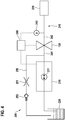
- FIG. 12 shows an SCR system 200 that includes the shutoff valve 100 according to the first, second or third exemplary embodiment. Furthermore, it comprises a delivery module 210, which comprises a pump 211, which is set up to deliver reducing agent from a reducing agent tank 220 and to suck it back into the reducing agent tank 22 by reversing the direction of rotation.
- the delivery module 210 is connected to a metering module 230 via a pressure line 240.
- the shut-off valve 100 is arranged in the pressure line 240 and divides it into two sections. A first section 241 of the pressure line 240 is located upstream of the shut-off valve 100, between the latter and the delivery module 210.
- a second section 242 of the pressure line 240 is located downstream of the shut-off valve 100, between the latter and the metering module 230. In the second section 242 of the pressure line 240 this is Furthermore, a pressure sensor 243 is arranged, which monitors the pressure p in the second section 242 - and optionally, when the shut-off valve 100 is open, also in the first section 241 - of the pressure line 240.
- the SCR system 200 includes a return line 250 that connects the first section 241 of the pressure line 240 to the reducing agent tank 220. A return throttle 251 and a check valve 252 are arranged in this return line 250. In another embodiment, the return throttle 251 or that Check valve 252 are removed.
- the shut-off valve 100, the pressure sensor 243 and the delivery module 210 are connected to an electronic control device 260 which controls them.
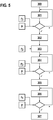
- FIG. 5 A flowchart of an exemplary embodiment of the method according to the invention for leakage detection and / or dosing quantity deviation detection is shown, as is carried out in the SCR system 200.
- the dosing module 230 remains closed throughout the process.
- the shut-off valve 100 opens.
- the pressure line 240 is filled 301 with reducing agent, as a result of which the pressure p increases in both parts 241 and 242 of the pressure line. If the pressure p in the entire pressure line 240 reaches a first pressure p 1 , at 7 bar, the pump 211 is switched off 302. As a result, the pressure p in the pressure line 240 drops.
- a further step 305 follows in which leak detection and / or dosing quantity deviation detection is carried out.
- the pressure p 2 which is included in the second section 242 of the pressure line 240, is observed over a predetermined period of 10 seconds. If the pressure p drops during the observed period, part of the fluid has to pass through one of the components of the metering module 230, pressure line 240, shut-off valve 100 or connecting pieces in between escape. Since the shut-off valve 100 is set up to prevent leakage in the best possible way, a leakage of the metering module 230 and / or the pressure line 240 can be detected therefrom. Furthermore, a deviation between the desired metering amount and the real metering amount, which is included in the second section 242 of the pressure line 240, can be recognized via the pressure and the amount of reducing agent conveyed.
- the pressure p in the first section 241 of the pressure line 240 is increased again in a further step 306 by the pump 211 being switched on again. If the pressure p reaches a fourth pressure p 4 , the shut-off valve 100 opens 307 again and the system can be diagnosed and metered.
- FIGS. 6a and 6b Diagrams are shown which show the pressure curve in the first section 241 and in the second section 242 of the pressure line 240 over time t.
- the shut-off valve 100 opens 300 at a pressure p of 5.6 bar.
- the pressure curve in the first section 241 and second section 242 of the pressure line 240 is the same in both figures. If the pressure p 1 is reached at 7 bar, an oscillation of the pressure p can be seen. This is due to the equalization of the pressure p in the entire pressure line 240.
- the pump 211 is then switched off 302. The pressure drops to the second pressure p 2 , which is 3.5 bar.
Landscapes
- Engineering & Computer Science (AREA)
- General Engineering & Computer Science (AREA)
- Mechanical Engineering (AREA)
- Chemical & Material Sciences (AREA)
- Chemical Kinetics & Catalysis (AREA)
- Combustion & Propulsion (AREA)
- Physics & Mathematics (AREA)
- Health & Medical Sciences (AREA)
- Toxicology (AREA)
- Fluid Mechanics (AREA)
- General Physics & Mathematics (AREA)
- Magnetically Actuated Valves (AREA)
Description
- Die vorliegende Erfindung betrifft ein Absperrventil. Des Weiteren betrifft die Erfindung ein SCR-System, welches dieses Absperrventil umfasst sowie ein Verfahren zur Leckagedetektion und/oder Dosiermengenabweichungserkennung in besagtem SCR-System. Darüber hinaus betrifft die vorliegende Erfindung ein Computerprogramm, das jeden Schritt des Verfahrens ausführt, wenn sie auf einem Rechengerät abläuft, sowie ein maschinenlesbares Speichermedium, welches das Computerprogramm speichert. Schließlich betrifft die Erfindung ein elektronisches Steuergerät, welches eingerichtet ist, um das Verfahren auszuführen.
- Absperrventile werden zur Steuerung von Fluidbewegungen genutzt. Dabei geben sie in einem geöffneten Zustand die Strömungsrichtung eines Fluids vor und verhindern in einem geschlossenen Zustand die Bewegung des Fluids. Absperrventile werden heutzutage in SCR-Systemen eingesetzt um eine Bewegung eines Reduktionsmittels (AdBlue®) zu steuern. Insbesondere sind Absperrventile in einer Druckleitung des SCR-Systems zwischen einem Fördermodul und einem Dosiermodul angeordnet. Dort sollen sie eine Leckage des Reduktionsmittels in die Druckleitung verhindert, da sonst die Möglichkeit besteht, dass dieses einfriert und sensible Bauteile beschädigt werden.
- Ein Beispiel für ein Absperrventil, wie oben beschrieben, wird in der Druckschrift
DE 10 2011 090 070 A1 gegeben. Diese betrifft ein Absperrventil, welches in einem SCR-System zum Einsatz gebracht wird. Es handelt sich dabei um ein 2/2-Wegeventil, bei dem ein Membranschieber, mittels einer Membranfeder, auf eine Membran gedrückt wird. Der Durchlasszustand wird über eine Magnetspule realisiert und kann dann selbstständig, bei erreichtem Minimaldruck in Durchlassrichtung im System, geöffnet bleiben. Das Absperrventil verhindert im geschlossenen Zustand, respektive bei geschlossenem Membranschieber, eine Leckage. - Ebenso betrifft die Druckschrift
DE 10 2012 204 104 A1 ein Absperrventil, das in einer Vorrichtung zur Belüftung eines Abgasnachbehandlungssystems angeordnet ist. Dabei ist das Absperrventil zwischen Fördermodul und Dosiermodul in einer Förderleitung angeordnet. Das 2/2-Wegeventil wird über einen Aktuator hydraulisch betätigt, daher ist hier kein Magnet notwendig. Von der Förderleitung zweigt eine Steuerleitung ab, die zum Steuern des Aktuators verwendet wird. Herrscht nun, im Fördermodus, Überdruck in der Förderleitung, wird der Aktuator aktiviert und öffnet das Ventil. - Des Weiteren betrifft die Druckschrift
DE 10 2012 211112 A1 ein Absperrventil, welches in einem SCR-System zum Einsatz gebracht wird. In diesem System wird das Umschalten zwischen Fördermodus und Rücklaufmodus über ein zusätzliches Schaltventil erreicht. Dieses Absperrventil besteht aus einem Wechselventil und einem 2/2-Wegeventil. Das Wechselventil öffnet das 2/2-Wegeventil, bei zwei unterschiedlichen Druckniveaus. Das hat zur Folge, dass das Absperrventil sowohl im Fördermodus, als auch im Rücksaugmodus, geöffnet werden kann. - Die Druckschrift
DE 10 2012 209 689 A1 betrifft eine Anordnung zur Abgasnachbehandlung mittels SCR. Darin werden ein Fördermodul, sowie ein Absperrventil beschrieben. Das Absperrventil verhindert mittels eines Absperrelements eine Leckage. Realisiert wird dies durch einen Dichtstempel, welcher im geschlossenen Zustand dicht auf dem Dichtsitz aufliegt. Der geöffnete Zustand wird mithilfe eines bistabilen Federelements erreicht, welches den Dichtstempel mit niedriger Haltekraft gegen die Aufschlagfläche drückt. Das bistabile Federelement sorgt hierbei für eine hohe Schließkraft und eine niedrige Haltekraft. Dies ermöglicht eine Nutzung des Ventils, ohne aktives Ansteuern, sodass das Ventil in dieser Anordnung vorzugsweise passiv genutzt wird. - Die
US 2014/0374635 A1 beschreibt ein Gasventil mit einem Einlass, einem Auslass und einem Verbindungsloch, das den Einlass und den Auslass verbindet. Ein Ventilsitz wirkt mit dem Verbindungsloch zusammen, um ein Durchströmen zu unterbinden. Ferner weist das Ventil ein Magnetjoch, eine Magnetspule und einen Magnetanker auf. An dem Magnetanker ist eine Membran angeordnet, welche das Verbindungsloch abdichten kann. Eine Druckfeder ist um die Magnetspule herum angeordnet und presst den Magnetanker mit der Membran gegen das Verbindungsloch. Um das Ventil zu öffnen, wird die Magnetspule aktiviert, sodass der Ventilsitz in eine offene Position bewegt wird und dort gehalten wird. - Die
DE 10 2014 218 088 A1 beschreibt ein hydraulisches Förder- und Dosiersystem mit wenigstens einem Absperrventil und ein Verfahren zum Betreiben eines solchen Förder- und Dosiersystems, mit dem auf einen Dosiermengenfehler geschlossen werden kann. Das Absperrventil kann als aktives Ventil, passives Ventil oder hybrides Ventil ausgebildet sein. Das aktive Ventil wird zur Ansteuerung immer bestromt. Das passive Ventil kann als ein Rückschlagventil oder eine Kombination aus zwei Rückschlagventilen ausgebildet sein. Für den Fall eines Rückschlagventils ist der Dosiermodus unbestromt möglich und der Rücksaugmodus wird bestromt durchgeführt, ein Absperrmodus ist hingegen nicht vorgesehen. Für den Fall von zwei kombinierten Rückschlagventilen sind ein stromloser Dosiermodus und ein stromloser Sperrmodus möglich, allerdings werden die Ventile für den Rücksaugmodus nicht bestromt. Das hybride Ventil ist eine Kombination aus aktivem und passivem Ventil. Der Dosiermodus und der Sperrmodus sind unbestromt möglich. Ein Rücksaugmodus wird durch aktives Ansteuern des Absperrventils erreicht. - Es wird ein Absperrventil vorgeschlagen, welches zur Steuerung einer Fluidbewegung eingerichtet ist. Insbesondere soll das Absperrventil, wenn es einen Sperrmodus annimmt, eine Bewegung des Fluids, sowie eine Leckage, verhindern. Zu diesem Zweck umfasst es ein Magnetjoch, eine Magnetspule, sowie eine Druckfeder. Außerdem umfasst das Absperrventil eine Führung und einen Führungsbolzen, der in die Führung eingeschoben wird. Die Führung ist mit einem Magnetanker verbunden, an dem eine elastische Membran angeordnet ist, wobei die Membran auf mindestens einem Fluidanschluss dichtschließend anpressbar ist. Die Druckfeder ist so angeordnet, dass sie die Magnetspule und gegebenenfalls den Magnetanker umschließt. Der Magnetanker kann dabei insbesondere als Flachanker oder als Tauchanker ausgeführt sein.
- Je nach Ausführungsbeispiel kann die Führung unterschiedlich ausgestaltet sein. In einer Version sind Führungsbuchsen innerhalb der Magnetspule ausgebildet, in die der Führungsbolzen eingeschoben wird. Alternativ können auch Gleitlagerbuchsen oder eine Gleitlagerschicht an einer Zwischenscheibe ausgebildet sein, an der Magnetanker an diesen Gleitlagerbuchsen bzw. Gleitlagerschicht entlang reibt und dadurch geführt wird. Um eine möglichst hohe Haltbarkeit zu gewährleisten werden die Gleitlagerbuchsen bzw. die Gleitlagerschicht vorzugsweise aus Nickel oder anderen härteren Beschichtungen hergestellt und der Magnetanker aus magnetischem Edelstahl. Zusätzlich wird der Magnetanker vorzugsweise von dem Führungsbolzen gestützt. Die Führung hat den Vorteil, dass Querkräfte die auf den Magnetanker wirken kompensiert werden können.
- Ein weiterer Aspekt der Führung betrifft eine Übertragung von Wärmeenergie aus der Magnetspule zu einem Fluidanschluss. Die Führung kann so ausgebildet sein, dass sie an dem Magnetjoch anliegt. Somit entstehen Wärmeübertragungsflächen über die Wärmeenergie von der Magnetspule zum Führungsbolzen übertragen werden kann. Da die Führung ebenfalls mit dem Magnetanker verbunden ist, kann die Wärmeenergie über die Membran an den Fluidanschluss weitergegeben werden. Infolgedessen bietet die Führung einen zusätzlichen Vorteil, indem sie beim Auftauprozess eines Fluids im Fluidanschluss oder zu dessen Gefrierschutz beiträgt.
- Gemäß eines Aspekts wird das Absperrventil in einem SCR-System verwendet. Das SCR-System umfasst eine Pumpe in einem Fördermodul und ein Dosiermodul, die durch eine Druckleitung miteinander verbunden sind. Das oben beschriebene Absperrventil ist in der Druckleitung angeordnet. Des Weiteren umfasst die Druckleitung einen Drucksensor, der zwischen Absperrventil und Dosiermodul angeordnet ist. Dieses SCR-System hat den Vorteil, dass eine Grundleckage durch Pumpenspalte einer Pumpe, die durch Drehrichtungsumkehr fördern und rücksaugen kann, verhindert wird.
- Die Membran, die Druckfeder, der Magnetanker, die Führung und der Führungsbolzen sind derart eingerichtet, dass das Absperrventil die folgenden Modi annehmen kann. In einem Sperrmodus wird die Membran, durch die Federkraft der Druckfeder auf den Magnetanker, stromlos sowohl auf einen Fluideinlass als auch einen Fluidauslass gedrückt und verschließt beide dicht, wenn der Druck am Fluideinlass und am Fluidauslass unterhalb eines festgelegten Drucks liegt. Das bietet den Vorteil, dass das Absperrventil im Sperrmodus eine Absperrung gegen einen Unterdruck und einen Überdruck, die unterhalb des festgelegten Drucks liege, sowohl aus dem Fluideinlass als auch aus dem Fluidauslass sicherstellt. Des Weiteren ist ein Dosiermodus vorgesehen, in dem das Absperrventil ab dem festgelegten Druck hydraulisch stromlos geöffnet wird und durch den Druck offen bleibt. Dadurch ist kein aktives Ansteuern in einem Dosierbetrieb des SCR-Systems notwendig. Darüber hinaus ist ein Rücksaugmodus vorgesehen, in dem eine Magnetkraft zwischen dem Magnetjoch und dem Magnetanker das Absperrventil in einer offenen Position hält. Dies ermöglicht ein Rücksaugen eines Reduktionsmittels aus der Druckleitung des SCR-Systems.
- Ein weiterer Aspekt des Absperrventils betrifft einen Eisdruckschutz des SCR-Systems. Das gefrierende Reduktionsmittel führt zu einem Eisdruck, der zu einem Verdrängen eines Volumens führen kann. Die Membran kann am Fluideinlass in Richtung des Ventilinneren gedrückt werden, ohne dass das Absperrventil durchlässig wird. Dadurch wird ein Eisdruck-Verdrängungsvolumen definiert.
- Das Verfahren zur Leckagedetektion und/oder Dosiermengenabweichungserkennung wird in dem oben beschriebenen SCR-System, inklusive Absperrventil eingesetzt. Hierbei umfasst das Verfahren folgende Schritte: Zu Beginn öffnet das Absperrventil, sodass ein Befüllen der Druckleitung mit Reduktionsmittel ermöglicht wird. Daraufhin wird das Absperrventil geschlossen und ein Druck stromabwärts des Absperrventils, also zwischen Absperrventil und Dosiermodul, in der Druckleitung eingeschlossen. Der eingeschlossene Druck wird durch den Drucksensor überwacht. Nun wird ein Druck stromaufwärts des Absperrventils, also zwischen Absperrventil und Fördermodul, durch Abschalten der Pumpe, abgesenkt. In einem weiteren Schritt kann eine Leckagedetektion und/oder Dosiermengenabweichungserkennung durchgeführt werden, indem ausgenutzt wird, dass der Druck stromabwärts des Absperrventils, wie oben beschrieben, mittels des Drucksensors, überwacht wird. Optional kann das Absperrventil durch Federkraft der Druckfeder geschlossen werden. Dies bietet den Vorteil, dass das Absperrventil selbstständig geschlossen wird und auch bleibt, ohne dass Strom zugeführt werden muss. Die Druckfeder kann zusätzlich eine Kraft aufbringen, um die Membran gegen einen Fuideinlass und einen Fluidauslass zu drücken, wenn der Druck stromaufwärts des Absperrventils abgesenkt wird. Dadurch wird ein gleichzeitiges Schließen beider Öffnungen erreicht. Dies führt dazu, dass weder der Unterdruck, aufgrund der Pumpe, stromaufwärts des Absperrventils, noch der Überdruck durch den eingeschlossenen Druck, stromabwärts des Absperrventils, zu einem Öffnen des Absperrventils führt. Zudem ist es nicht nötig, das Absperrventil während der Leckagedetektion und/oder der Dosiermengenabweichungserkennung mit Strom zu versorgen.
- Gemäß eines Aspekts, kann beim Befüllen der Druckleitung mit Reduktionsmittel ein erster Druck im System aufgebaut werden. Dieser liegt insbesondere in einem Bereich von 5,8 bar bis 10 bar. Anschließend wird Druck auf einen zweiten Druck, der insbesondere zwischen 2 bar und 5,5 bar liegt, reduziert, woraufhin das Absperrventil schließt. Dadurch wird garantiert, dass sich der Druck überall im SCR-System ausgleicht. Der Druckabfall kann beispielsweise über eine Drossel oder ein Rückschlagventil realisiert werden, die einen Rücklauf mit einem Abschnitt der Druckleitung stromaufwärts des Absperrventils verbindet. Der zweite Druck wird somit in der Druckleitung zwischen Absperrventil und Dosiermodul eingeschlossen und kann zur Leckagedetektion und/oder zur Dosiermengenabweichungserkennung verwendet werden. Daraufhin wird der Druck stromaufwärts des Absperrventils durch die Pumpe auf einen dritten Druck, zwischen 1 bar und 2 bar, abgesenkt. Dies führt zu einer Druckdifferenz zwischen Fluideinlass und Fluidauslass des Absperrventils, die ein Schließen des Absperrventils bewirkt.
- Die Leckagedetektion wird vorzugsweise ausgeführt, indem der eingeschlossene Druck stromabwärts des Absperrventils (zweiter Druck) über eine festgelegte Zeitspanne von 0,5 bis 30 Sekunden vom Drucksensor detektiert wird. Ändert sich der eingeschlossene Druck während dieser Zeitspanne, kann auf eine Leckage in der Druckleitung oder im Dosiermodul geschlossen werden.
- Ist die Leckagedetektion und/oder die Dosiermengenabweichungserkennung abgeschlossen, kann der Druck stromaufwärts des Absperrventils, also aufseiten der Pumpe, wieder auf einen vierten Druck erhöht werden. Dieser kann wiederum insbesondere in einem Bereich von 4,8 bar bis 10 bar liegen. Als Resultat ist das SCR-System diagnostiziert und dosierfähig.
- Das Computerprogramm ist eingerichtet, jeden Schritt des Verfahrens durchzuführen, insbesondere, wenn es auf einem Rechengerät oder Steuergerät durchgeführt wird. Es ermöglicht die Implementierung des Verfahrens in einem herkömmlichen elektronischen Steuergerät, ohne hieran bauliche Veränderungen vornehmen zu müssen. Hierzu ist es auf dem maschinenlesbaren Speichermedium gespeichert.
- Durch Aufspielen des Computerprogramms auf ein herkömmliches elektronisches Steuergerät, wird das elektronische Steuergerät erhalten, welches eingerichtet ist, eine Leckagedetektion und/oder Dosiermengenabweichungserkennung durchzuführen.
- Ausführungsbeispiele der Erfindung sind in den Zeichnungen dargestellt und in der nachfolgenden Beschreibung näher erläutert.
-
Figur 1 zeigt schematisch ein Absperrventil gemäß einer Ausführungsform der Erfindung. -
Figur 2 zeigt schematisch ein Absperrventil gemäß einer weiteren Ausführungsform der Erfindung. -
Figur 3 zeigt schematisch ein Absperrventil gemäß noch einer weiteren Ausführungsform der Erfindung. -
Figur 4 zeigt schematisch ein SCR-System gemäß einer Ausführungsform der Erfindung. -
Figur 5 zeigt ein Ablaufdiagramm eines Ausführungsbeispiels des erfindungsgemäßen Verfahrens. -
Figur 6a zeigt ein Diagramm eines Drucks in einem ersten Abschnitt der Druckleitung in einem SCR-System gemäß einem Ausführungsbeispiel der Erfindung über die Zeit. -
Figur 6b zeigt ein Diagramm eines Drucks in einem ersten Abschnitt der Druckleitung in einem SCR-System gemäß einem Ausführungsbeispiel der Erfindung über die Zeit. - In
Figur 1 ist ein Absperrventil 100, gemäß eines ersten Ausführungsbeispiels der Erfindung, gezeigt. Es umfasst ein Magnetjoch 101, welches eine Magnetspule 102 umfasst, die von einem Spulenträger 103 gehalten wird. Umschlossen werden das Magnetjoch 101 sowie der Spulenträger 103, inklusive Magnetspule 102, von einer Magnetumfassung 104. Außerdem umfasst das Absperrventil 100 einen Flachanker 105, an dem eine elastische Membran 106 angeordnet ist. Dabei besteht die Membran 106 aus HNBR (Hydrierter Acrylnitrilbutadien-Kautschuk) und wird auf den Flachanker 105 aufgespritzt oder aufvulkanisiert. Der Flachanker 105 wiederum ist mit einem Ende einer Druckfeder 107 verbunden, das den Rand der Mantelfläche des Flachankers 105 umläuft. In einer weiteren Ausführungsform kann ein Tauchanker, statt des Flachankers 105 verwendet werden. Ein anderes Ende der Druckfeder 107 ist auf so eine Weise mit dem Magnetjoch 101 verbunden, dass die Druckfeder 107 den Spulenträger 103, inklusive Magnetspule 102 in ihrem Inneren umschließt. Ein Fluideinlass 108 und ein Fluidauslass 109 sind so angeordnet, dass die Membran 106 auf beiden dichtschließend anpressbar ist und beide damit verschließt. - Des Weiteren umfasst das Absperrventil 100 einen Führungsbolzen 110, der mit dem Flachanker 105 verbunden ist sowie eine Führungsbuchse 111, in die der Führungsbolzen 110 eingeschoben werden kann. Die Führungsbuchse 111 besteht aus zwei Teilen, die innerhalb der Magnetspule 102 entlang ihrer Spulenachse auf einer gemeinsamen Linie angeordnet. Der Führungsbolzen erstreckt sich geöffneten Zustand des Absperrventils bis über beide Führungsbuchsen 111 bis zum Rand des Magnetjochs 101. Infolgedessen wird der Führungsbolzen 110 in solcher Weise von der Führungsbuchse 111 gehalten, dass sich dieser nur noch entlang der Achse der Druckfeder 107 bewegen kann. Aus diesem Grund wirkt der Führungsbolzen 110, zusammen mit der Führungsbuchse 111, als Führung für den Flachanker 105.
- Da die Führungsbuchse 111 mit dem Führungsbolzen 110 sowie dem Magnetjoch 101 und somit mit der Magnetspule 102 verbunden ist, kann Wärmeenergie zwischen Magnetspule 102 und Führungsbolzen 110 über Wärmeübergangsflächen übertragen werden. Anschließend wird die Wärmeenergie über den Flachanker 105 weiter an die Membran 106 übertragen, die die Wärmeenergie dann in die Fluidanschlüsse 108 und 109 abgeben kann, wo sie zum Auftauen einer Flüssigkeit, bzw. zu deren Gefrierschutz beiträgt.
-
Figur 2 zeigt ein zweites Ausführungsbeispiel des erfindungsgemäßen Absperrventils 100. Es umfasst bis auf die Führungselemente im Wesentlichen dieselben Bauteile, die inFigur 1 beschrieben wurden und diese haben im Wesentlichen dieselbe Funktion. Es wird daher auf eine erneute Beschreibung dieser verzichtet. In diesem Ausführungsbeispiel ist ein Führungsbolzen 120 ebenfalls mit dem Flachanker 105verbunden. Dieser kann in einer weiten Ausführungsform als Tauchanker ausgebildet sein. Dabei erstreckt sich der Führungsbolzen 120 von der Membranseite des Absperrventils 100 aus in den Flachanker 105 und wird von diesem umschlossen, wodurch er diesen stützt. An einem Zwischenring 121, der an der Magnetumfassung 104 angeordnet ist, ist eine Gleitlagerbuchse 122 angeordnet. Der Flachanker 105 wird von dieser Gleitlagerbuchse 122 geführt, indem er an deren Innseite entlang reibt. Es ist anzumerken, dass der Führungsbolzen 120 nicht ins Innere der Magnetspule 102 eindringt, wie im ersten Ausführungsbeispiel, sondern im Wesentlichen auf die Länge der Gleitreibungsbuchse begrenzt ist. -
Figur 3 zeigt ein drittes Ausführungsbeispiel des erfindungsgemäßen Absperrventils 100. Das dritte Ausführungsbeispiel unterscheidet sich vom zweiten Ausführungsbeispiel inFigur 2 lediglich in der Gestaltung der Führung. Es wird daher auf eine erneute Beschreibung der identischen Bauteile verzichtet. Im dritten Ausführungsbeispiel ist ein Führungsbolzen 130 analog zum zweiten Ausführungsbeispiel mit dem Flachanker 105 verbunden. Dieser kann in einer weiten Ausführungsform als Tauchanker ausgebildet sein. Gleichermaßen erstreckt sich der Führungsbolzen 130 von der Membranseite des Absperrventils 100 aus in den Flachanker 105 und wird von diesem umschossen, wodurch er diesen stützt. Auf einem Zwischenring 131, der an der Magnetumfassung 104 angeordnet ist, wird statt der Gleitlagerbuchse 122 eine Gleitlagerschicht 132 aufgebracht. Nun reibt der Flachanker an der Gleitlagerschicht 132 des Zwischenrings 131 entlang und wird infolgedessen durch diese geführt. Auch hier dringt der Führungsbolzen 120 nicht ins Innere der Magnetspule 102 ein, wie im ersten Ausführungsbeispiel, sondern ist im Wesentlichen auf die Länge der Gleitreibungsschicht begrenzt. - In der zweiten und dritten Ausführungsform wird jeweils ein geeignetes Material für die Gleitlagerbuchse 122 bzw. die Gleitlagerschicht 132 verwendet werden, mit dem eine große Anzahl Hübe ohne Abnutzung möglich ist. In diesem Fall wird Nickel verwendet, das 0,1-10 Millionen Hübe übersteht. Der Flachanker 105 ist an der Fläche, mit der er an der Gleitlagerbuchse 122 bzw. der Gleitlagerschicht 132 reibt, geschliffen bzw. poliert.
- Das Absperrventil 100 nimmt, je nach Bedingung oder Einsatz, unterschiedliche Modi an. In einem Sperrmodus drückt die Druckfeder 107 den Flachanker 105 in Richtung des Fluideinlasses 108 und des Fluidauslasses 109, sodass die Membran 106 beide gleichzeitig verschließt. Somit wird das Absperrventil 100 durch die Federkraft der Druckfeder 107 geschlossen und es wird keine Stromzufuhr benötigt. Dadurch wird verhindert, dass ein Fluid durch das Absperrventil strömen kann. Die Federkraft der Druckfeder 107 hält das Absperrventil auch geschlossen, wenn ein Unter- oder Überdruck am Fluideinlass 108 und Fluidauslass 109 vorliegt, solange dieser klein genug ist, beispielsweise unter 5,6 bar.
- Ein weiterer Modus ermöglicht dem Fluid vom Fluideinlass zum Fluidauslass zu strömen. In diesem Dosiermodus herrscht im Fluideinlass 108 ein so großer Druck p, der gegen die Membran 106 und somit gegen den Flachanker 105 drückt, dass dieser die Federkraft der Druckfeder 107 überwindet. Dadurch wird der Flachanker 105 in Richtung Magnetjoch 101 gedrückt und eine Verbindung zwischen Fluideinlass 108 und Fluidauslass 109 ist gegeben. In dem vorliegenden Ausführungsbeispiel beträgt dieser Druck p 5,6 bar. Bei diesem Modus ist ebenfalls keine Stromzufuhr notwendig. Die Membran öffnet druckunterstützt und bietet, bei anliegendem Druck p von 4 bis 10 bar im System, keinen Druckverlust.
- Darüber hinaus nimmt das Absperrventil 100 einen Rücksaugmodus an, indem die Magnetspule 102 angesteuert wird. Diese stellt eine Magnetkraft zwischen Magnetjoch 101 und Flachanker 105 bereit, was zur Folge hat, dass der Flachanker 105 zum Magnetjoch 101 hin gezogen wird und die Federkraft der Druckfeder 107 überwunden wird. Dabei wird eine Verbindung zwischen Fluidauslass 109 und Fluideinlass 108 hergestellt bzw. gehalten, durch die Fluid strömen kann.
- Da die Membran 106 elastisch ist, ist es möglich diese zu verformen. Am Fluideinlass ist es daher möglich die Membran 106 zwischen dem Flachanker 105 und der Magnetumfassung 104 in das Innere des Absperrventils zu drücken. Allerdings verschließt die Membran 106 im Sperrmodus weiterhin sowohl den Fluideinlass 108, als auch den Fluidauslass 109. Aus diesem Grund wird nur ein zusätzliches Volumen ausgebildet. Dieses Volumen kann genutzt werden, wenn das Fluid eine Flüssigkeit ist, die sich beim Gefrieren ausdehnt, indem es als Eisdruck-Verdrängungsvolumen fungiert.
-
Figur 4 zeigt ein SCR-System 200, das das Absperrventil 100 gemäß dem ersten, zweiten oder dritten Ausführungsbeispiel umfasst. Des Weiteren umfasst es ein Fördermodul 210, welches eine Pumpe 211 umfasst, die eingerichtet ist Reduktionsmittel aus einem Reduktionsmitteltank 220 zu fördern und es mittels Drehrichtungsumkehr in den Reduktionsmitteltank 22 zurückzusaugen. Das Fördermodul 210 ist mit einem Dosiermodul 230 über eine Druckleitung 240 verbunden. Das Absperrventil 100 ist in der Druckleitung 240 angeordnet und teilt diese in zwei Abschnitte. Ein erster Abschnitt 241 der Druckleitung 240 befindet sich stromaufwärts des Absperrventils 100, zwischen diesem und dem Fördermodul 210. Ein zweiter Abschnitt 242 der Druckleitung 240 liegt stromabwärts des Absperrventils 100, zwischen diesem und dem Dosiermodul 230. Im zweiten Abschnitt 242 der Druckleitung 240 ist des Weiteren ein Drucksensor 243 angeordnet, der den Druck p im zweiten Abschnitt 242 - und gegebenenfalls, bei geöffnetem Absperrventil 100, ebenfalls im ersten Abschnitt 241 - der Druckleitung 240 überwacht. Darüber hinaus umfasst das SCR-System 200 eine Rückförderleitung 250, die den ersten Abschnitt 241 der Druckleitung 240 mit dem Reduktionsmitteltank 220 verbindet. In dieser Rückförderleitung 250 ist eine Rücklaufdrossel 251 und ein Rückschlagventil 252 angeordnet. In einer anderen Ausführungsform kann die Rücklaufdrossel 251 oder das Rückschlagventil 252 entfernt werden. Das Absperrventil 100, der Drucksensor 243 und das Fördermodul 210 sind mit einem elektronischen Steuergerät 260 verbunden, das diese steuert. - In
Figur 5 ist ein Ablaufdiagramm eines Ausführungsbeispiels des erfindungsgemäßen Verfahrens zur Leckagedetektion und/oder Dosiermengenabweichungserkennung dargestellt, wie es im SCR-System 200 ausgeführt wird. Das Dosiermodul 230 bleibt während des gesamten Verfahrens geschlossen. In einem ersten Schritt 300 öffnet das Absperrventil 100. Bei angeschalteter Pumpe 211 erfolgt eine Befüllung 301 der Druckleitung 240 mit Reduktionsmittel, wodurch der Druck p in beiden Teilen 241 und 242 der Druckleitung steigt. Erreicht der Druck p in der gesamten Druckleitung 240 einen ersten Druck p1, bei 7 bar, wird die Pumpe 211 ausgeschaltet 302. Als Folge dessen, sinkt der Druck p in der Druckleitung 240. Erreicht der Druck p nun einen zweiten Druck p2, bei 3,5 bar, überwindet die Federkraft der Druckfeder 107 den Druck p und das Absperrventil 100 schließt 303. Dadurch wird der zweite Druck p2 im zweiten Abschnitt 242 der Druckleitung 240 eingeschlossen. Anschließend erfolgt ein weiteres Absenken 304 des Drucks p im ersten Abschnitt 241 der Druckleitung 240, bis ein dritter Druck p3, bei 1,5 bar, erreicht wird. - Es folgt ein weiterer Schritt 305, in dem eine Leckagedetektion und/oder Dosiermengenabweichungserkennung durchgeführt wird. Bei der Leckagedetektion wird der Druck p2, der im zweiten Abschnitt 242 der Druckleitung 240 eingeschlossen ist über einen vorgegebenen Zeitraum von 10 Sekunden beobachtet Sinkt der Druck p während des beobachteten Zeitraums ab, muss ein Teil des Fluids durch eines der Bauteile Dosiermodul 230, Druckleitung 240, Absperrventil 100 oder dazwischen befindlichen Verbindungsstücken entweichen. Da das Absperrventil 100 so eingerichtet ist, eine Leckage bestmöglich zu unterbinden, kann daraus eine Leckage des Dosiermoduls 230 und/oder der Druckleitung 240 detektiert werden. Des Weiteren kann, über den Druck und die geförderte Menge Reduktionsmittel, eine Abweichung zwischen gewünschter Dosiermenge und realer Dosiermenge, die im zweiten Abschnitt 242 der Druckleitung 240 eingeschlossen ist, erkannt werden.
- Ist die Leckagedetektion und/oder die Dosiermengenabweichungserkennung abgeschlossen, wird in einem weiteren Schritt 306 der Druck p im ersten Abschnitt 241 der Druckleitung 240, wieder erhöht, indem die Pumpe 211 erneut eingeschaltet wird. Erreicht der Druck p einen vierten Druck p4, öffnet 307 das Absperrventil 100 erneut und das System ist diagnostizier und dosierfähig.
- In den
Figuren 6a und 6b sind Diagramme aufgezeigt, die den Druckverlauf im ersten Abschnitt 241 sowie im zweiten Abschnitt 242 der Druckleitung 240 über der Zeit t darstellen. Das Absperrventil 100 öffnet 300 bei einem Druck p von 5,6 bar. Im Zeitraum zwischen dem Öffnen 300 und dem Schließen 303 des Absperrventils 100 beim zweiten Druck p2 ist der Druckverlauf im ersten Abschnitt 241 und zweiten Abschnitt 242 der Druckleitung 240 in beiden Figuren gleich. Wird der Druck p1 bei 7 bar erreicht, ist ein Einschwingen des Drucks p zu erkennen. Dieser ist auf den Ausgleich des Drucks p im der gesamten Druckleitung 240 zurückzuführen. Anschließend erfolgt das Abschalten 302 der Pumpe 211. Der Druck sinkt auf den zweiten Druck p2, der bei 3,5 bar liegt. Bei diesem zweiten Druck p2 schließt das Absperrventil 100, wie oben beschrieben. Der Druckverlauf im ersten Abschnitt 241, der inFigur 6a dargestellt ist, unterscheidet sich nun vom Druckverlauf im zweiten Abschnitt 242 der Druckleitung 240 inFigur 6b . Während der Druck p im ersten Abschnitt 241 auf einen dritten Druck p3, bei 1,5 bar absinkt, bleibt der Druck zunächst konstant. InFigur 6b sind zwei Fälle dargestellt. Zum einen bleibt der Druck p ab dem Erreichen des zweiten Drucks p2 bei einem konstanten Druck pk. Zum Anderen ist ein Abfallen des Drucks p hin zu einem Druck pL zu erkennen. Aus diesem Abfall des Drucks pL kann wie oben beschrieben auf eine Leckage geschlossen werden.
Claims (15)
- Absperrventil (100), umfassend ein Magnetjoch (101), eine Magnetspule (102) und eine Druckfeder (107) sowie eine Führung (111, 122, 132), einen Führungsbolzen (110, 120, 130) und einen mit dem Führungsbolzen (110, 120, 130) verbundenen Magnetanker (105), an dem eine elastische Membran (106) angeordnet ist, wobei die Membran (106) auf mindestens einem Fluidanschluss (108, 109) dichtschließend anpressbar ist und die Druckfeder (107) so angeordnet ist, dass sie die Magnetspule (102) umschließt; wobei die Membran (101), die Druckfeder (107), der Magnetanker (105), die Führung (111, 122, 132) und der Führungsbolzen (110, 120, 130) derart eingerichtet sind, dass das Absperrventil (100) die folgenden Modi annehmen kann:- einen Sperrmodus, in dem die Membran (101) durch die Federkraft der Druckfeder (107) sowohl einen Fluideinlass (108) als auch einen Fluidauslass (109) stromlos verschließt, wenn der Druck (p) am Fluideinlass (108) und am Fluidauslass (109) unter einem festgelegten Druck (p2) liegt;- einen Dosiermodus, in dem das Absperrventil (100) stromlos öffnet, wenn der Druck (p) am Fluideinlass (108) und/oder am Fluidauslass (109) über dem festgelegten Druck (p2) liegt;- und einen Rücksaugmodus, in dem eine Magnetkraft zwischen dem Magnetjoch (101) und dem Magnetanker (105) das Absperrventil (100) in einer offenen Position hält.
- Absperrventil nach Anspruch 1, dadurch gekennzeichnet, dass der Magnetanker ein Flachanker oder ein Tauchanker ist.
- Absperrventil (100) nach Anspruch 1 oder 2, dadurch gekennzeichnet, dass die Führung als mindestens eine Führungsbuchse (111) innerhalb der Magnetspule (102) ausgebildet ist und der Führungsbolzen (110) in diese eingeschoben ist.
- Absperrventil (100) nach Anspruch 1 oder 2, dadurch gekennzeichnet, dass die Führung als Gleitlagerbuchsen (122) ausgebildet ist und der Magnetanker (105) an diesen Gleitlagerbuchsen (122) entlang reibt und vom Führungsbolzen (120) gestützt ist.
- Absperrventil (100) nach Anspruch 1 oder 2, dadurch gekennzeichnet, dass die Führung als Gleitlagerschicht (132) ausgebildet ist und der Magnetanker (105) an dieser Gleitlagerschicht (132) entlang reibt und vom Führungsbolzen (130) gestützt ist.
- SCR-System (200), das eine Pumpe (211) und ein Dosiermodul (230), die durch eine Druckleitung (240) miteinander verbunden sind, sowie ein Absperrventil (100) gemäß einem der Ansprüche 1 bis 5 in der Druckleitung (140) und einen Drucksensor (243), der in der Druckleitung (240) zwischen Absperrventil (100) und Dosiermodul (230) angeordnet ist, umfasst.
- Verfahren zur Leckagedetektion und/oder Dosiermengenabweichungserkennung bei einem SCR-System (200) gemäß Anspruch 6, wobei das Absperrventil (100) einen Druck (p) in der Druckleitung (240) einschließt und dieser durch den Drucksensor (243) überwacht wird, umfassend folgende Schritte:- Öffnen (300) des Absperrventils (100);- Befüllen (301) der Druckleitung (240) mit Reduktionsmittel;- Schließen (303) des Absperrventils (100);- Absenken (304) eines Drucks (p) stromaufwärts des Absperrventils (100) durch Abschalten (302) der Pumpe (211);- Durchführen (305) einer Leckagedetektion und/oder Dosiermengenabweichungserkennung durch Überwachen des Drucks (p) stromabwärts des Absperrventils, mittels des Drucksensors (243).
- Verfahren nach Anspruch 7, dadurch gekennzeichnet, dass das Absperrventil (100) durch Federkraft der Druckfeder (107) geschlossen wird.
- Verfahren nach Anspruch 8, dadurch gekennzeichnet, dass eine Kraft, die die Membran (106) gegen einen Fluideinlass (108) und einen Fluidauslass (109) drückt, durch die Druckfeder (107) aufgebracht wird, wenn der Druck (p) stromaufwärts des Absperrventils (100) abgesenkt wird (304).
- Verfahren nach einem der Ansprüche 7 bis 9, dadurch gekennzeichnet, dass beim Befüllen (301) der Druckleitung (240) mit Reduktionsmittel ein erster Druck(p1) im SCR-System (200) aufgebaut wird, dieser dann auf einen zweiten Druck (p2) reduziert wird, bei dem das Absperrventil (100) geschlossen wird und dann der Druck (p) stromaufwärts des Absperrventils (100) durch Abschalten (302) die Pumpe (211) auf einen dritten Druck (p3) abgesenkt wird.
- Verfahren nach einem der Ansprüche 7 bis 10, dadurch gekennzeichnet, dass zur Leckagedetektion ein Absinken des eingeschlossenen Drucks (p) stromabwärts des Absperrventils (100) über eine festgelegte Zeitspanne vom Drucksensor (243) detektiert wird.
- Verfahren nach einem der Ansprüche 7 bis 11, dadurch gekennzeichnet, dass nach der Leckagedetektion und/oder der Dosiermengenabweichungserkennung der Druck (p) stromaufwärts des Absperrventils (100) bis zu einem vierten Druck (p4) erhöht wird (306) und das Absperrventil (100) geöffnet wird (307), wenn der vierte Druck (p4) überschritten wurde.
- Computerprogramm, welches eingerichtet ist und Befehle umfasst, die bei der Ausführung des Programms durch einen Computer oder ein elektronisches Gerät diesen veranlassen, jeden Schritt des Verfahrens nach einem der Ansprüche 7 bis 12 durchzuführen.
- Maschinenlesbares Speichermedium, auf welchem ein Computerprogramm nach Anspruch 13 gespeichert ist.
- Elektronisches Steuergerät (260), welches eingerichtet ist, um mittels eines Verfahrens nach einem der Ansprüche 7 bis 12 eine Leckagedetektion und/oder Dosiermengenabweichungserkennung durchzuführen.
Applications Claiming Priority (2)
| Application Number | Priority Date | Filing Date | Title |
|---|---|---|---|
| DE102016208611.1A DE102016208611A1 (de) | 2016-05-19 | 2016-05-19 | Absperrventil, SCR-System und Verfahren zur Leckagedetektion und/oder Dosiermengenabweichungserkennung |
| PCT/EP2017/057079 WO2017198380A1 (de) | 2016-05-19 | 2017-03-24 | Absperrventil, scr-system und verfahren zur leckagedetektion und/oder dosiermengenabweichungserkennung |
Publications (2)
| Publication Number | Publication Date |
|---|---|
| EP3458752A1 EP3458752A1 (de) | 2019-03-27 |
| EP3458752B1 true EP3458752B1 (de) | 2020-06-17 |
Family
ID=58413091
Family Applications (1)
| Application Number | Title | Priority Date | Filing Date |
|---|---|---|---|
| EP17713631.4A Not-in-force EP3458752B1 (de) | 2016-05-19 | 2017-03-24 | Absperrventil, scr-system und verfahren zur leckagedetektion und/oder dosiermengenabweichungserkennung |
Country Status (6)
| Country | Link |
|---|---|
| US (1) | US20190170047A1 (de) |
| EP (1) | EP3458752B1 (de) |
| KR (1) | KR20190008561A (de) |
| CN (1) | CN109312877B (de) |
| DE (1) | DE102016208611A1 (de) |
| WO (1) | WO2017198380A1 (de) |
Families Citing this family (11)
| Publication number | Priority date | Publication date | Assignee | Title |
|---|---|---|---|---|
| DE102017200832A1 (de) * | 2017-01-19 | 2018-07-19 | Robert Bosch Gmbh | Expansionskörper und Verfahren zur Überwachung eines Drucksensors bei einem SCR-System mit Expansionskörper |
| US10544876B2 (en) * | 2018-04-18 | 2020-01-28 | Chin-Yuan Chen | Solenoid valve for irrigation systems |
| JP7115328B2 (ja) | 2019-01-15 | 2022-08-09 | 株式会社デンソー | 電磁弁 |
| EP4425022A3 (de) | 2019-09-12 | 2025-03-12 | A. Raymond Et Cie | Durchflussregelventil und system zur reinigung einer fahrzeugoberfläche |
| US12202446B2 (en) | 2019-09-12 | 2025-01-21 | A. Raymond Et Cie | Flow control valve and system for cleaning a vehicle surface |
| CN111879482B (zh) * | 2020-07-23 | 2022-08-12 | 广船国际有限公司 | 通海仪表电缆管用的挡水监控装置及船舶 |
| CN112212059B (zh) * | 2020-10-19 | 2022-08-05 | 斯必克(上海)流体技术有限公司 | 一种带有管道压力检测的防倒流电磁阀 |
| CN112922706B (zh) * | 2021-04-06 | 2021-09-28 | 宜兴市锦龙陶瓷有限公司 | 一种薄壁柴油机尾气净化用蜂窝陶瓷烧结装置及其使用方法 |
| CN115217810B (zh) * | 2022-07-05 | 2025-01-17 | 上海航空机械有限公司 | 一种反向开启的插装式截止阀及方法 |
| DE102022207728A1 (de) * | 2022-07-27 | 2024-02-01 | Robert Bosch Gesellschaft mit beschränkter Haftung | Verfahren zur Diagnose eines Ventils |
| DE102024112016B4 (de) * | 2024-04-29 | 2026-03-12 | Bürkert Werke GmbH & Co. KG | Magnetventil |
Citations (2)
| Publication number | Priority date | Publication date | Assignee | Title |
|---|---|---|---|---|
| JPH07243542A (ja) * | 1994-01-12 | 1995-09-19 | Toyo Electric Mfg Co Ltd | 電磁操作機能を有する逆止弁 |
| DE102004018567B3 (de) * | 2004-04-16 | 2005-12-15 | Dichtungstechnik G. Bruss Gmbh & Co. Kg | Rückschlagventil |
Family Cites Families (15)
| Publication number | Priority date | Publication date | Assignee | Title |
|---|---|---|---|---|
| JPS6318869Y2 (de) * | 1981-02-05 | 1988-05-26 | ||
| CN2156360Y (zh) * | 1993-03-28 | 1994-02-16 | 陈银和 | 清洁自动水龙头 |
| DE10343940A1 (de) * | 2003-09-23 | 2005-04-14 | Robert Bosch Gmbh | Magnetventil mit geräuschreduzierender Dämpferscheibe |
| CN1330901C (zh) * | 2005-08-28 | 2007-08-08 | 俞毓成 | 通电启闭机械保持电磁阀 |
| DE102005050276A1 (de) * | 2005-10-20 | 2007-04-26 | Robert Bosch Gmbh | Magnetventil |
| DE102008020042A1 (de) * | 2008-04-21 | 2009-10-22 | Pierburg Gmbh | Elektromagnetventil |
| DE102008063933A1 (de) * | 2008-12-22 | 2010-07-01 | Ipgate Ag | 2/2 Magnetventil |
| US20110072888A1 (en) * | 2009-04-22 | 2011-03-31 | Eaton Corporation | Method for leak detection in dosing system |
| DE102011090070A1 (de) | 2011-12-29 | 2013-07-04 | Robert Bosch Gmbh | Abgasnachbehandlungsanordnung und Verfahren zur Abgasnachbehandlung |
| EP2634485A1 (de) * | 2012-02-28 | 2013-09-04 | Coprececitec, S.L. | Gasventil und Methode zur Montage eines Gasventils |
| DE102012204104A1 (de) | 2012-03-15 | 2013-09-19 | Robert Bosch Gmbh | Absperrventil |
| DE102012209689B4 (de) | 2012-06-11 | 2024-11-07 | Robert Bosch Gmbh | Vorrichtung mit einem Ventil zur Bereitstellung einer Durchlassstellung und einer Schließstellung für ein Abgasnachbehandlungssystem und Abgasnachbehandlungssystem |
| DE102012211112A1 (de) | 2012-06-28 | 2014-01-02 | Robert Bosch Gmbh | Vorrichtung zum Verhindern des Rücklaufens eines Fluids |
| DE102012215394A1 (de) * | 2012-08-30 | 2014-03-06 | Robert Bosch Gmbh | Vorrichtung zur Diagnose eines Dosiersystems und Verfahren zum Betreiben der Vorrichtung |
| DE102014218088A1 (de) * | 2014-09-08 | 2016-03-10 | Robert Bosch Gmbh | Verfahren zum Betreiben eines hydraulischen Förder- und Dosiersystems für ein flüssiges Reaktionsmittel |
-
2016
- 2016-05-19 DE DE102016208611.1A patent/DE102016208611A1/de not_active Withdrawn
-
2017
- 2017-03-24 KR KR1020187036331A patent/KR20190008561A/ko not_active Withdrawn
- 2017-03-24 US US16/302,250 patent/US20190170047A1/en not_active Abandoned
- 2017-03-24 WO PCT/EP2017/057079 patent/WO2017198380A1/de not_active Ceased
- 2017-03-24 EP EP17713631.4A patent/EP3458752B1/de not_active Not-in-force
- 2017-03-24 CN CN201780030599.5A patent/CN109312877B/zh not_active Expired - Fee Related
Patent Citations (2)
| Publication number | Priority date | Publication date | Assignee | Title |
|---|---|---|---|---|
| JPH07243542A (ja) * | 1994-01-12 | 1995-09-19 | Toyo Electric Mfg Co Ltd | 電磁操作機能を有する逆止弁 |
| DE102004018567B3 (de) * | 2004-04-16 | 2005-12-15 | Dichtungstechnik G. Bruss Gmbh & Co. Kg | Rückschlagventil |
Also Published As
| Publication number | Publication date |
|---|---|
| US20190170047A1 (en) | 2019-06-06 |
| WO2017198380A1 (de) | 2017-11-23 |
| KR20190008561A (ko) | 2019-01-24 |
| EP3458752A1 (de) | 2019-03-27 |
| CN109312877B (zh) | 2020-10-16 |
| CN109312877A (zh) | 2019-02-05 |
| DE102016208611A1 (de) | 2017-11-23 |
Similar Documents
| Publication | Publication Date | Title |
|---|---|---|
| DE102016208611A1 (de) | Absperrventil, SCR-System und Verfahren zur Leckagedetektion und/oder Dosiermengenabweichungserkennung | |
| DE102016208600A1 (de) | Absperrventil, SCR-System und Verfahren zur Leckagedetektion und/oder Dosiermengenabweichungserkennung | |
| EP1029158B1 (de) | Vorrichtung zur steuerung eines gaswechselventils für brennkraftmaschinen | |
| EP2748439B1 (de) | Dosiersystem für ein flüssiges reduktionsmittel | |
| EP2798193B1 (de) | Ventil | |
| EP2016278B1 (de) | Druckregelventil mit notfahr- und belüftungsfunktion | |
| DE2447741A1 (de) | Kolbenvorrichtung fuer eine membranpumpe | |
| DE102008041410A1 (de) | Dosiersystem für ein flüssiges Medium, insbesondere Harnstoff-Wasser-Lösung | |
| AT511252B1 (de) | Spülventil für common-rail schweröl- einspritzsysteme | |
| WO2015055411A1 (de) | Druckbegrenzungsventil für ein kraftstoffeinspritzsystem und kraftstoffeinspritzsystem | |
| EP2909478B1 (de) | Ventilbaugruppe für fördereinrichtung | |
| DE102009036364A1 (de) | Akkumulatorkraftstoffeinspritzungssystem | |
| EP1970556A1 (de) | Injektor | |
| WO2016198453A1 (de) | Volumenstromgeregeltes sitzventil | |
| EP2603680A1 (de) | Einspritzvorrichtung zum einbringen einer harnstofflösung in den abgasstrang einer brennkraftmaschine | |
| EP4172486A1 (de) | Durchflussbegrenzer für ein kraftstoffeinspritzsystem sowie kraftstoffeinspritzsystem mit einem durchflussbegrenzer | |
| DE102009021668A1 (de) | Stellanordnung, Schaltantrieb für eine derartige Stellanordnung und Ventilanordnung für eine derartige Stellanordnung | |
| EP4251880B1 (de) | Pumpenvorrichtung | |
| DE102014226476A1 (de) | Absperrventil für ein Dosiermodul und Verfahren zu seiner Diagnose | |
| EP3078456B1 (de) | Hydraulikantrieb | |
| EP3775527A1 (de) | Injektor zum einspritzen von kraftstoff | |
| DE102011084995A1 (de) | Wegeventil mit integrierter Drossel | |
| DE102012205370A1 (de) | 3/2-Wegeventil | |
| DE102018114656A1 (de) | Ventil für das Einspritzen von Wasser in ein Kraftstofffördermodul eines Verbrennungsmotors, Ventilmodul, Dosiermodul und Verbrennungsmotor | |
| DE102014226478A1 (de) | Absperrventil für ein Dosiersystem und Verfahren zur Diagnose eines Dosierventils des Dosiersystems |
Legal Events
| Date | Code | Title | Description |
|---|---|---|---|
| STAA | Information on the status of an ep patent application or granted ep patent |
Free format text: STATUS: UNKNOWN |
|
| STAA | Information on the status of an ep patent application or granted ep patent |
Free format text: STATUS: THE INTERNATIONAL PUBLICATION HAS BEEN MADE |
|
| PUAI | Public reference made under article 153(3) epc to a published international application that has entered the european phase |
Free format text: ORIGINAL CODE: 0009012 |
|
| STAA | Information on the status of an ep patent application or granted ep patent |
Free format text: STATUS: REQUEST FOR EXAMINATION WAS MADE |
|
| 17P | Request for examination filed |
Effective date: 20181219 |
|
| AK | Designated contracting states |
Kind code of ref document: A1 Designated state(s): AL AT BE BG CH CY CZ DE DK EE ES FI FR GB GR HR HU IE IS IT LI LT LU LV MC MK MT NL NO PL PT RO RS SE SI SK SM TR |
|
| AX | Request for extension of the european patent |
Extension state: BA ME |
|
| DAV | Request for validation of the european patent (deleted) | ||
| DAX | Request for extension of the european patent (deleted) | ||
| GRAP | Despatch of communication of intention to grant a patent |
Free format text: ORIGINAL CODE: EPIDOSNIGR1 |
|
| STAA | Information on the status of an ep patent application or granted ep patent |
Free format text: STATUS: GRANT OF PATENT IS INTENDED |
|
| INTG | Intention to grant announced |
Effective date: 20200113 |
|
| RAP1 | Party data changed (applicant data changed or rights of an application transferred) |
Owner name: ROBERT BOSCH GMBH |
|
| GRAS | Grant fee paid |
Free format text: ORIGINAL CODE: EPIDOSNIGR3 |
|
| GRAA | (expected) grant |
Free format text: ORIGINAL CODE: 0009210 |
|
| STAA | Information on the status of an ep patent application or granted ep patent |
Free format text: STATUS: THE PATENT HAS BEEN GRANTED |
|
| AK | Designated contracting states |
Kind code of ref document: B1 Designated state(s): AL AT BE BG CH CY CZ DE DK EE ES FI FR GB GR HR HU IE IS IT LI LT LU LV MC MK MT NL NO PL PT RO RS SE SI SK SM TR |
|
| REG | Reference to a national code |
Ref country code: GB Ref legal event code: FG4D Free format text: NOT ENGLISH |
|
| REG | Reference to a national code |
Ref country code: CH Ref legal event code: EP |
|
| REG | Reference to a national code |
Ref country code: IE Ref legal event code: FG4D Free format text: LANGUAGE OF EP DOCUMENT: GERMAN |
|
| REG | Reference to a national code |
Ref country code: DE Ref legal event code: R096 Ref document number: 502017005748 Country of ref document: DE |
|
| REG | Reference to a national code |
Ref country code: AT Ref legal event code: REF Ref document number: 1281720 Country of ref document: AT Kind code of ref document: T Effective date: 20200715 |
|
| PG25 | Lapsed in a contracting state [announced via postgrant information from national office to epo] |
Ref country code: LT Free format text: LAPSE BECAUSE OF FAILURE TO SUBMIT A TRANSLATION OF THE DESCRIPTION OR TO PAY THE FEE WITHIN THE PRESCRIBED TIME-LIMIT Effective date: 20200617 Ref country code: GR Free format text: LAPSE BECAUSE OF FAILURE TO SUBMIT A TRANSLATION OF THE DESCRIPTION OR TO PAY THE FEE WITHIN THE PRESCRIBED TIME-LIMIT Effective date: 20200918 Ref country code: SE Free format text: LAPSE BECAUSE OF FAILURE TO SUBMIT A TRANSLATION OF THE DESCRIPTION OR TO PAY THE FEE WITHIN THE PRESCRIBED TIME-LIMIT Effective date: 20200617 Ref country code: NO Free format text: LAPSE BECAUSE OF FAILURE TO SUBMIT A TRANSLATION OF THE DESCRIPTION OR TO PAY THE FEE WITHIN THE PRESCRIBED TIME-LIMIT Effective date: 20200917 Ref country code: FI Free format text: LAPSE BECAUSE OF FAILURE TO SUBMIT A TRANSLATION OF THE DESCRIPTION OR TO PAY THE FEE WITHIN THE PRESCRIBED TIME-LIMIT Effective date: 20200617 |
|
| REG | Reference to a national code |
Ref country code: LT Ref legal event code: MG4D |
|
| REG | Reference to a national code |
Ref country code: NL Ref legal event code: MP Effective date: 20200617 |
|
| PG25 | Lapsed in a contracting state [announced via postgrant information from national office to epo] |
Ref country code: RS Free format text: LAPSE BECAUSE OF FAILURE TO SUBMIT A TRANSLATION OF THE DESCRIPTION OR TO PAY THE FEE WITHIN THE PRESCRIBED TIME-LIMIT Effective date: 20200617 Ref country code: HR Free format text: LAPSE BECAUSE OF FAILURE TO SUBMIT A TRANSLATION OF THE DESCRIPTION OR TO PAY THE FEE WITHIN THE PRESCRIBED TIME-LIMIT Effective date: 20200617 Ref country code: LV Free format text: LAPSE BECAUSE OF FAILURE TO SUBMIT A TRANSLATION OF THE DESCRIPTION OR TO PAY THE FEE WITHIN THE PRESCRIBED TIME-LIMIT Effective date: 20200617 Ref country code: BG Free format text: LAPSE BECAUSE OF FAILURE TO SUBMIT A TRANSLATION OF THE DESCRIPTION OR TO PAY THE FEE WITHIN THE PRESCRIBED TIME-LIMIT Effective date: 20200917 |
|
| PG25 | Lapsed in a contracting state [announced via postgrant information from national office to epo] |
Ref country code: AL Free format text: LAPSE BECAUSE OF FAILURE TO SUBMIT A TRANSLATION OF THE DESCRIPTION OR TO PAY THE FEE WITHIN THE PRESCRIBED TIME-LIMIT Effective date: 20200617 Ref country code: NL Free format text: LAPSE BECAUSE OF FAILURE TO SUBMIT A TRANSLATION OF THE DESCRIPTION OR TO PAY THE FEE WITHIN THE PRESCRIBED TIME-LIMIT Effective date: 20200617 |
|
| PG25 | Lapsed in a contracting state [announced via postgrant information from national office to epo] |
Ref country code: CZ Free format text: LAPSE BECAUSE OF FAILURE TO SUBMIT A TRANSLATION OF THE DESCRIPTION OR TO PAY THE FEE WITHIN THE PRESCRIBED TIME-LIMIT Effective date: 20200617 Ref country code: RO Free format text: LAPSE BECAUSE OF FAILURE TO SUBMIT A TRANSLATION OF THE DESCRIPTION OR TO PAY THE FEE WITHIN THE PRESCRIBED TIME-LIMIT Effective date: 20200617 Ref country code: ES Free format text: LAPSE BECAUSE OF FAILURE TO SUBMIT A TRANSLATION OF THE DESCRIPTION OR TO PAY THE FEE WITHIN THE PRESCRIBED TIME-LIMIT Effective date: 20200617 Ref country code: PT Free format text: LAPSE BECAUSE OF FAILURE TO SUBMIT A TRANSLATION OF THE DESCRIPTION OR TO PAY THE FEE WITHIN THE PRESCRIBED TIME-LIMIT Effective date: 20201019 Ref country code: EE Free format text: LAPSE BECAUSE OF FAILURE TO SUBMIT A TRANSLATION OF THE DESCRIPTION OR TO PAY THE FEE WITHIN THE PRESCRIBED TIME-LIMIT Effective date: 20200617 Ref country code: SM Free format text: LAPSE BECAUSE OF FAILURE TO SUBMIT A TRANSLATION OF THE DESCRIPTION OR TO PAY THE FEE WITHIN THE PRESCRIBED TIME-LIMIT Effective date: 20200617 Ref country code: IT Free format text: LAPSE BECAUSE OF FAILURE TO SUBMIT A TRANSLATION OF THE DESCRIPTION OR TO PAY THE FEE WITHIN THE PRESCRIBED TIME-LIMIT Effective date: 20200617 |
|
| PG25 | Lapsed in a contracting state [announced via postgrant information from national office to epo] |
Ref country code: PL Free format text: LAPSE BECAUSE OF FAILURE TO SUBMIT A TRANSLATION OF THE DESCRIPTION OR TO PAY THE FEE WITHIN THE PRESCRIBED TIME-LIMIT Effective date: 20200617 Ref country code: SK Free format text: LAPSE BECAUSE OF FAILURE TO SUBMIT A TRANSLATION OF THE DESCRIPTION OR TO PAY THE FEE WITHIN THE PRESCRIBED TIME-LIMIT Effective date: 20200617 Ref country code: IS Free format text: LAPSE BECAUSE OF FAILURE TO SUBMIT A TRANSLATION OF THE DESCRIPTION OR TO PAY THE FEE WITHIN THE PRESCRIBED TIME-LIMIT Effective date: 20201017 |
|
| REG | Reference to a national code |
Ref country code: DE Ref legal event code: R097 Ref document number: 502017005748 Country of ref document: DE |
|
| PLBE | No opposition filed within time limit |
Free format text: ORIGINAL CODE: 0009261 |
|
| STAA | Information on the status of an ep patent application or granted ep patent |
Free format text: STATUS: NO OPPOSITION FILED WITHIN TIME LIMIT |
|
| PG25 | Lapsed in a contracting state [announced via postgrant information from national office to epo] |
Ref country code: DK Free format text: LAPSE BECAUSE OF FAILURE TO SUBMIT A TRANSLATION OF THE DESCRIPTION OR TO PAY THE FEE WITHIN THE PRESCRIBED TIME-LIMIT Effective date: 20200617 |
|
| 26N | No opposition filed |
Effective date: 20210318 |
|
| PG25 | Lapsed in a contracting state [announced via postgrant information from national office to epo] |
Ref country code: SI Free format text: LAPSE BECAUSE OF FAILURE TO SUBMIT A TRANSLATION OF THE DESCRIPTION OR TO PAY THE FEE WITHIN THE PRESCRIBED TIME-LIMIT Effective date: 20200617 |
|
| PG25 | Lapsed in a contracting state [announced via postgrant information from national office to epo] |
Ref country code: MC Free format text: LAPSE BECAUSE OF FAILURE TO SUBMIT A TRANSLATION OF THE DESCRIPTION OR TO PAY THE FEE WITHIN THE PRESCRIBED TIME-LIMIT Effective date: 20200617 |
|
| REG | Reference to a national code |
Ref country code: CH Ref legal event code: PL |
|
| GBPC | Gb: european patent ceased through non-payment of renewal fee |
Effective date: 20210324 |
|
| REG | Reference to a national code |
Ref country code: BE Ref legal event code: MM Effective date: 20210331 |
|
| PG25 | Lapsed in a contracting state [announced via postgrant information from national office to epo] |
Ref country code: GB Free format text: LAPSE BECAUSE OF NON-PAYMENT OF DUE FEES Effective date: 20210324 Ref country code: IE Free format text: LAPSE BECAUSE OF NON-PAYMENT OF DUE FEES Effective date: 20210324 Ref country code: LI Free format text: LAPSE BECAUSE OF NON-PAYMENT OF DUE FEES Effective date: 20210331 Ref country code: LU Free format text: LAPSE BECAUSE OF NON-PAYMENT OF DUE FEES Effective date: 20210324 Ref country code: CH Free format text: LAPSE BECAUSE OF NON-PAYMENT OF DUE FEES Effective date: 20210331 |
|
| PG25 | Lapsed in a contracting state [announced via postgrant information from national office to epo] |
Ref country code: BE Free format text: LAPSE BECAUSE OF NON-PAYMENT OF DUE FEES Effective date: 20210331 |
|
| PGFP | Annual fee paid to national office [announced via postgrant information from national office to epo] |
Ref country code: FR Payment date: 20230320 Year of fee payment: 7 |
|
| REG | Reference to a national code |
Ref country code: AT Ref legal event code: MM01 Ref document number: 1281720 Country of ref document: AT Kind code of ref document: T Effective date: 20220324 |
|
| PG25 | Lapsed in a contracting state [announced via postgrant information from national office to epo] |
Ref country code: CY Free format text: LAPSE BECAUSE OF FAILURE TO SUBMIT A TRANSLATION OF THE DESCRIPTION OR TO PAY THE FEE WITHIN THE PRESCRIBED TIME-LIMIT Effective date: 20200617 |
|
| PG25 | Lapsed in a contracting state [announced via postgrant information from national office to epo] |
Ref country code: HU Free format text: LAPSE BECAUSE OF FAILURE TO SUBMIT A TRANSLATION OF THE DESCRIPTION OR TO PAY THE FEE WITHIN THE PRESCRIBED TIME-LIMIT; INVALID AB INITIO Effective date: 20170324 Ref country code: AT Free format text: LAPSE BECAUSE OF NON-PAYMENT OF DUE FEES Effective date: 20220324 |
|
| REG | Reference to a national code |
Ref country code: DE Ref legal event code: R084 Ref document number: 502017005748 Country of ref document: DE |
|
| PG25 | Lapsed in a contracting state [announced via postgrant information from national office to epo] |
Ref country code: MK Free format text: LAPSE BECAUSE OF FAILURE TO SUBMIT A TRANSLATION OF THE DESCRIPTION OR TO PAY THE FEE WITHIN THE PRESCRIBED TIME-LIMIT Effective date: 20200617 |
|
| PGFP | Annual fee paid to national office [announced via postgrant information from national office to epo] |
Ref country code: DE Payment date: 20240527 Year of fee payment: 8 |
|
| PG25 | Lapsed in a contracting state [announced via postgrant information from national office to epo] |
Ref country code: MT Free format text: LAPSE BECAUSE OF FAILURE TO SUBMIT A TRANSLATION OF THE DESCRIPTION OR TO PAY THE FEE WITHIN THE PRESCRIBED TIME-LIMIT Effective date: 20200617 |
|
| PG25 | Lapsed in a contracting state [announced via postgrant information from national office to epo] |
Ref country code: FR Free format text: LAPSE BECAUSE OF NON-PAYMENT OF DUE FEES Effective date: 20240331 |
|
| PG25 | Lapsed in a contracting state [announced via postgrant information from national office to epo] |
Ref country code: FR Free format text: LAPSE BECAUSE OF NON-PAYMENT OF DUE FEES Effective date: 20240331 |
|
| REG | Reference to a national code |
Ref country code: DE Ref legal event code: R119 Ref document number: 502017005748 Country of ref document: DE |
|
| PG25 | Lapsed in a contracting state [announced via postgrant information from national office to epo] |
Ref country code: TR Free format text: LAPSE BECAUSE OF FAILURE TO SUBMIT A TRANSLATION OF THE DESCRIPTION OR TO PAY THE FEE WITHIN THE PRESCRIBED TIME-LIMIT Effective date: 20200617 |
|
| PG25 | Lapsed in a contracting state [announced via postgrant information from national office to epo] |
Ref country code: DE Free format text: LAPSE BECAUSE OF NON-PAYMENT OF DUE FEES Effective date: 20251001 |