EP3456879B1 - Bodenverdichtungsvorrichtung - Google Patents
Bodenverdichtungsvorrichtung Download PDFInfo
- Publication number
- EP3456879B1 EP3456879B1 EP18190928.4A EP18190928A EP3456879B1 EP 3456879 B1 EP3456879 B1 EP 3456879B1 EP 18190928 A EP18190928 A EP 18190928A EP 3456879 B1 EP3456879 B1 EP 3456879B1
- Authority
- EP
- European Patent Office
- Prior art keywords
- vibration plate
- motor
- vibration
- electric motor
- mass
- Prior art date
- Legal status (The legal status is an assumption and is not a legal conclusion. Google has not performed a legal analysis and makes no representation as to the accuracy of the status listed.)
- Active
Links
Images


Classifications
-
- E—FIXED CONSTRUCTIONS
- E02—HYDRAULIC ENGINEERING; FOUNDATIONS; SOIL SHIFTING
- E02D—FOUNDATIONS; EXCAVATIONS; EMBANKMENTS; UNDERGROUND OR UNDERWATER STRUCTURES
- E02D3/00—Improving or preserving soil or rock, e.g. preserving permafrost soil
- E02D3/02—Improving by compacting
- E02D3/046—Improving by compacting by tamping or vibrating, e.g. with auxiliary watering of the soil
- E02D3/074—Vibrating apparatus operating with systems involving rotary unbalanced masses
-
- E—FIXED CONSTRUCTIONS
- E02—HYDRAULIC ENGINEERING; FOUNDATIONS; SOIL SHIFTING
- E02D—FOUNDATIONS; EXCAVATIONS; EMBANKMENTS; UNDERGROUND OR UNDERWATER STRUCTURES
- E02D3/00—Improving or preserving soil or rock, e.g. preserving permafrost soil
- E02D3/02—Improving by compacting
- E02D3/046—Improving by compacting by tamping or vibrating, e.g. with auxiliary watering of the soil
-
- B—PERFORMING OPERATIONS; TRANSPORTING
- B06—GENERATING OR TRANSMITTING MECHANICAL VIBRATIONS IN GENERAL
- B06B—METHODS OR APPARATUS FOR GENERATING OR TRANSMITTING MECHANICAL VIBRATIONS OF INFRASONIC, SONIC, OR ULTRASONIC FREQUENCY, e.g. FOR PERFORMING MECHANICAL WORK IN GENERAL
- B06B1/00—Methods or apparatus for generating mechanical vibrations of infrasonic, sonic, or ultrasonic frequency
- B06B1/10—Methods or apparatus for generating mechanical vibrations of infrasonic, sonic, or ultrasonic frequency making use of mechanical energy
- B06B1/16—Methods or apparatus for generating mechanical vibrations of infrasonic, sonic, or ultrasonic frequency making use of mechanical energy operating with systems involving rotary unbalanced masses
- B06B1/161—Adjustable systems, i.e. where amplitude or direction of frequency of vibration can be varied
-
- E—FIXED CONSTRUCTIONS
- E01—CONSTRUCTION OF ROADS, RAILWAYS, OR BRIDGES
- E01C—CONSTRUCTION OF, OR SURFACES FOR, ROADS, SPORTS GROUNDS, OR THE LIKE; MACHINES OR AUXILIARY TOOLS FOR CONSTRUCTION OR REPAIR
- E01C19/00—Machines, tools or auxiliary devices for preparing or distributing paving materials, for working the placed materials, or for forming, consolidating, or finishing the paving
- E01C19/22—Machines, tools or auxiliary devices for preparing or distributing paving materials, for working the placed materials, or for forming, consolidating, or finishing the paving for consolidating or finishing laid-down unset materials
- E01C19/30—Tamping or vibrating apparatus other than rollers ; Devices for ramming individual paving elements
- E01C19/34—Power-driven rammers or tampers, e.g. air-hammer impacted shoes for ramming stone-sett paving; Hand-actuated ramming or tamping machines, e.g. tampers with manually hoisted dropping weight
- E01C19/38—Power-driven rammers or tampers, e.g. air-hammer impacted shoes for ramming stone-sett paving; Hand-actuated ramming or tamping machines, e.g. tampers with manually hoisted dropping weight with means specifically for generating vibrations, e.g. vibrating plate compactors, immersion vibrators
Definitions
- the invention relates to a vibration plate for soil compaction, with an upper mass and a lower mass, which is elastically coupled to the upper mass, with a vibration exciter device.
- vibration plates are already well known and are used to compact loose ground in construction. For example, when backfilling construction pits or backing up sand and gravel, the material must be compacted in order to create the necessary load-bearing capacity. Only then can a final tar layer or plaster be applied.
- Vibration plates have proven themselves because they are available in different sizes and weight classes, so that a suitable machine is available for the respective application.
- rollers can also be used, but due to their size and the associated increased transport costs, they are only used for larger areas.
- Vibratory plates are usually driven by internal combustion engines.
- the internal combustion engine is arranged on the upper mass.
- the driving force of the motor is transmitted from the upper mass by means of a belt drive or via a hydraulic connection to a vibration exciter, which is arranged on the lower mass.
- the transmission of the drive force by means of belts or hydraulic lines often leads to problems due to the elastic coupling between the upper and lower mass and requires at least regular maintenance and control.
- the internal combustion engine is maintenance-sensitive and generates harmful exhaust gases to which the operator is exposed in poorly ventilated construction site areas, such as a ditch.
- a plate vibrator with an electric drive is known.
- An electricity storage device is mounted on the upper mass of the plate vibrator.
- a vibration exciter is arranged on the lower mass and has an electric drive motor.
- the invention is based on the object of specifying a vibration plate which reduces the disadvantages of the known vibration plates and has a simple and low-maintenance design.
- a vibration plate for soil compaction comprises an upper mass on which at least one energy storage element is arranged.
- the upper mass is elastically coupled to a lower mass which has at least one ground contact plate and a vibration exciter device which acts on the lower mass.
- the vibration exciter device has at least one electric motor which rotatably drives at least one rotatably mounted unbalanced mass and which can be driven by means of the electrical energy of the at least one energy storage element.
- Such a vibration plate does not generate any harmful exhaust gases due to the use of electrical energy as the driving force.
- the motor which provides the drive force for the unbalanced mass, is arranged on the lower mass, so that no mechanical or hydraulic energy has to be transferred from the upper mass to the lower mass.
- a shaft of the electric motor can extend transversely to a longitudinal axis of the vibration plate. This arrangement is advantageous for driving the unbalanced masses. There is no need to redirect the rotation.
- the longitudinal axis of the vibration plate is defined on the basis of the direction of advance of the vibration plate. During operation, the vibrating plate moves in a forward direction with the front end of the vibrating plate in front, while the operator guides the vibrating plate on a handle at the rear end of the vibrating plate. The longitudinal axis extends centrally from the front end of the vibrating plate to the rear end of the vibrating plate.
- the vibration exciter device can have an electric motor with two unbalanced masses, the electric motor being arranged axially between the two unbalanced masses.
- the unbalanced masses are rotatably connected to the shaft of the electric motor. With the central arrangement of the motor between the unbalanced masses, an even weight distribution on the lower mass is achieved. In addition, the storage of the two unbalanced masses and the motor shaft is also made easier
- the at least one electric motor is designed as a brushless electric motor, in particular as an electric motor of the BLDC motor, SR motor or asynchronous motor types.
- So-called BLDC motors are also under the names Brushless DC motor or brushless DC motor known.
- SR motors are also known under the term reluctance motors. All these motors are characterized by their brushless design and thus their essentially maintenance-free and wear-free operation. The motors work reliably for a long time and can also be used in the rough everyday work on the construction site.
- the vibration exciter device has at least two electric motors each with associated unbalanced masses, the electric motors together with the associated unbalanced masses being arranged spatially separated from one another on the lower mass.
- the use of two electric motors with their respective unbalanced masses improves the movement behavior of the vibration plate.
- the vibration plate is more comfortable for the operator to operate than when only using an electric motor with the associated unbalanced mass.
- the at least two electric motors can be arranged in a staggered manner along the longitudinal axis of the vibration plate. This type of arrangement distributes the drive force of the unbalanced masses more evenly on the vibrating plate and leads to a better compaction result.
- the vibration plate has an electronic control which controls and / or regulates the direction of rotation and the rotational speed of the at least one electric motor.
- the monitoring of the energy store such as a so-called battery management system, can also be integrated in the electronic control.
- the electronic controller can be designed to control and / or regulate the direction of rotation and / or the rotational speed of at least two electric motors and to set them independently of one another.
- independent control of the two motors can result in advantageous movement properties of the vibration plate.
- reverse travel of the vibration plate can thus be set if the electric motors are set in such a way that the resulting force vectors of the respective unbalanced masses cause reverse travel.
- static vibration can also be set, or a variation of the advance speed.
- the electronic control is arranged on the lower mass.
- the electrical connections between the controller and the electric motor (s) are very short. This improves the response time of the electric motors or the motor. Since the motors, as a rule, rotate very quickly during operation and in particular Brushless electric motors require very fast control or regulation commands, the spatially close arrangement of the individual components has advantages.
- the energy storage element is arranged decoupled from vibrations on the upper mass.
- the lower mass is connected to the upper mass in a sprung manner. Nevertheless, the upper mass and thus also the energy storage element are exposed to vibrations.
- the service life of the energy storage element can be extended if the vibrations are kept from it as best as possible. Vibration decoupling can be achieved, for example, by arranging rubber buffers between the energy storage unit and the upper mass.
- Fig. 1 shows a highly schematic side view of a variant of the vibration plate (1) according to the invention with an upper mass (2) and a lower mass (5).
- the upper mass (2) comprises a support frame (11) which is connected to a support plate (12). Furthermore, in the exemplary embodiment shown, the upper mass comprises at least one energy storage element (3) and an electronic controller (10), which are arranged on the support frame (11). Furthermore, the upper mass (2) comprises an irrigation device (14) and a guide bracket or drawbar (13) by means of which an operator can control the vibration plate.
- At least one control element is arranged on the drawbar (13), by means of which an operator can control and / or regulate the function of the vibration plate, i.e. in particular can switch the vibration plate on and off.
- the drawbar (13) is arranged on the upper mass (2) in a vibration-decoupled manner, so that harmful vibrations are only transmitted to the drawbar and thus to an operator in a reduced manner.
- the irrigation device (14) comprises a container for holding water which, when the vibration plate is in operation, can be dispensed from a controlled, closable and openable outlet onto the soil to be compacted. This is particularly advantageous when compacting tar, in order to prevent the vibration plate from sticking to the tar.
- the upper mass is connected to the lower mass (5) by means of damping elements (15).
- the lower mass (5) comprises a soil contact plate (4) on which the vibration plate (1) moves over the soil to be compacted and acts on it.
- the lower mass (5) comprises a vibration exciter device (6) which generates mechanical vibrations and transmits them to the ground contact plate (4) to which it is connected.
- the energy storage element (3) is arranged on the upper mass (2) in a vibration-damped manner.
- the energy storage element (3) is arranged on a holder (16) which is connected to the upper mass (2) in a vibration-damped manner.
- the energy storage element (3) can also be in contact with the upper mass by means of vibration dampers such as rubber buffers.
- the electronic control (10) can also be arranged on the upper mass (2) in a vibration-damped manner, for example by also being arranged on the holder (16).
- the electronic control (10) is used to control and / or regulate the vibration exciter device (6).
- the electronic control (10) is designed to influence and adjust the electric motor (7) of the vibration exciter device (6), i.e. in particular to adjust and vary its speed and direction of rotation. If an embodiment according to the invention provides a vibration exciter device (6) with several electric motors, the electronic control (10) is designed to set and influence the respective electric motors (7) independently of one another. In a variant, it is also possible to control one or more electric motors (7) as a function of the state of one or more other electric motors (7). For example, the speed and / or direction of rotation of a first electric motor (7) can serve as a reference for a further electric motor (7), on the basis of which the further electric motor (7) is then set.
- FIG. 2 shows an exemplary vibration exciter device (6).
- the vibration exciter device (6) comprises an electric motor (7) by means of which at least one
- Unbalance mass (8) can be set in rotation.
- the unbalanced mass (8) is preferably connected to the motor shaft (9) of the electric motor (7).
- the electric motor (7) is preferably arranged between two unbalanced masses (8) so that it is positioned centrally and axially between the unbalanced masses (8).
- the motor shaft (9) of the electric motor (7) can be led out of the motor housing on both sides of the electric motor.
- the unbalanced masses (8) can be attached to the two ends of the motor shaft.
- the motor shaft (9) can also be designed in such a way that the unbalanced masses (8) are an integral part of the motor shaft (9).
- This variant makes it possible for two electric motors to be axially aligned with one another, the motor shafts (9) of the electric motors (7) being led out of the motor housings on the opposite sides facing away from the motors, with an unbalanced mass ( 8) is arranged.
- the electric motors can be controlled independently of one another and, by means of different directions of rotation and / or speed, apply different centrifugal forces to the lower mass, which enables different driving maneuvers.
- the vibration exciter device (6) is mechanically self-sufficient in terms of drive from the upper mass (2), i.e. the vibration exciter device is only supplied with electrical energy.
- the electric motor (7) generates the mechanical force from the electrical energy to drive the unbalanced mass (s) (8). This means that the vibration exciter device is only supplied with electrical energy and it is not connected to the upper mass by means of a belt drive or a hydraulic system.
- the electric motor (7) is connected to the upper mass with an electrical cable, which is not shown in the figures.
- FIG 3 shows a highly schematic plan view of a ground contact plate (4) with a vibration exciter device (6).
- the vibration exciter device (6) is arranged on the ground contact plate (4) and is firmly connected to it.
- the vibration exciter device (6) is arranged centrally in the longitudinal direction, ie in the middle of the ground contact plate (4), the motor shaft running transversely to the longitudinal direction of the vibration plate.
- the vibration exciter device (6) is arranged in a front half of the ground contact plate (4). This positioning gives the vibrating plate (1) the best movement properties.
- the vibration exciter device (6) is particularly preferably arranged in a front third of the ground contact plate (4).
- the vibration plate (1) can move when using a
- Figure 4 shows a variant of the vibration plate (1) with two electric motors (7) or unbalance exciters.
- a first electric motor (7) is arranged in a first half of the soil contact plate (4) and a second electric motor (7) in a second half of the soil contact plate (4).
- the use of two electric motors (7) leads to an improved compaction performance and a more uniform movement behavior of the vibrating plate (1).
- the motor shafts (9) of the two electric motors (7) are aligned parallel to one another and run transversely to the longitudinal axis of the vibration plate.
- a vibrating plate (1) of this type can not only move forwards but also backwards and shake while standing.
- the basic technical principles for this are known from the prior art, which is why they will not be discussed in more detail.
- either forward travel, reverse travel or static vibration can be set.
- the speed of movement can be continuously adjusted between a maximum forward speed and a maximum reverse speed. This is achieved by means of the electronic control, which can control and set the electric motors (7) independently of one another.
- the vibration plate (1) moves towards the operator, i.e. in the direction of the end of the vibration plate on which the guide bracket (13) is arranged.
- FIG. 5 Another variant is in Figure 5 shown, in addition to the two electric motors (7) as in Figure 4 at least one further electric motor (7) is also arranged on the ground contact plate (4).
- Two electric motors (7) with motor shafts (9) are arranged transversely to the longitudinal axis of the vibration plate (1) and at least one further electric motor (7) with the motor shaft longitudinally, ie arranged parallel to the longitudinal axis.
- two electric motors (7) are aligned with the motor shafts parallel to the longitudinal axis.
- the vibrating plate (1) By means of this arrangement it is possible to design the vibrating plate (1) so that it is directionally controllable. If direction control is used in the following, rotation of the vibration plate (1) around the vertical axis is meant. In this case, the vibration plate (1) can be controlled not only forwards and backwards, but also to the left and right, for example. For this purpose, the directions of rotation and speeds of the electric motors (7) aligned along the longitudinal axis are adjusted to the operator's desire to drive, so that corresponding centrifugal forces are generated that move the vibration plate (1) in the desired direction.
- the electronic control is designed accordingly to control the respective number of electric motors (7) individually and independently of one another.
- FIG. 6 Another possibility for controlling the direction of a vibration plate (1) results from the design of the variant as shown in Figure 6 is shown.
- three electric motors (7) are arranged on the ground contact plate (4).
- Two electric motors (7) are axially aligned with one another. If a higher centrifugal force, ie speed, is set in one of the axially aligned electric motors (7) than in the other axially aligned electric motor (7), the vibration plate moves in its direction. If both axially aligned electric motors (7) run in the same direction of rotation and at the same speed, forward travel results.
- FIG. 7 Another possibility for controlling the direction of a vibration plate (1) results from the design of the variant as shown in Figure 7 is shown.
- three electric motors (7) are arranged on the ground contact plate (4).
- Two electric motors (7) are arranged at an angle to one another. That is, the motor axes (17) of the electric motors (7) formed by the motor shafts (9) intersect.
- a directional control is also available with the construction according to Figure 8 possible.
- four electric motors (7) are arranged on the ground contact plate (4).
- Two electric motors (7) are each axially aligned with one another.
- Two more electric motors (7) are staggered in front of or behind them and are axially aligned with one another.
- the rotary movement can be increased by turning the two electric motors (7) to the other side of the longitudinal axis in the opposite direction.
- FIG. 8 Alternatively to the construction according to Figure 8 is also an arrangement of the electric motors (7) as in Figure 9 shown possible.
- the electric motors (7) are arranged at an angle to one another in such a way that the motor axis (17) of one electric motor (7) intersects with the motor axes (17) of two other electric motors (7).
- the electric motors are therefore all arranged at an angle to the longitudinal axis of the vibration plate (1), ie arranged in such a way that the motor axes (17) of all electric motors intersect with the longitudinal axis of the vibration plate (1).
- the point of intersection of the motor axes (17) of two electric motors (7) preferably lies on the longitudinal axis of the vibration plate (1).
- the arrangement can be chosen so that at least two of the electric motors (7) are arranged in a mirror image to the longitudinal axis.
- Four electric motors (7) are preferably arranged in mirror image to the longitudinal axis.
- Such an arrangement offers advantages with regard to the straight running of the vibration plate and also improves the steerability, i.e. the rotation around the vertical axis.
- FIG. 10 Another variant for the construction of a vibration plate according to the invention is shown in Figure 10 shown.
- the energy storage element (3) is formed therein from a multiplicity of individual accumulators which are arranged on the upper mass (2) and interconnected with one another.
- An electronic controller (10) is provided to control the motor or motors.
- the electronic control (10) is arranged on the upper mass (2).
- the vibration exciter device (6) is constructed with just one electric motor (7) which drives two unbalanced masses (8).
- the energy storage element in general, it is possible, i.e. regardless of the embodiments presented, to form the energy storage element from individual battery cells.
- the battery cells can be replaced individually.
- the charging module can be structurally integrated with the electronic control.
Landscapes
- Engineering & Computer Science (AREA)
- Structural Engineering (AREA)
- Life Sciences & Earth Sciences (AREA)
- Civil Engineering (AREA)
- Environmental & Geological Engineering (AREA)
- Soil Sciences (AREA)
- General Life Sciences & Earth Sciences (AREA)
- Mining & Mineral Resources (AREA)
- Paleontology (AREA)
- Agronomy & Crop Science (AREA)
- General Engineering & Computer Science (AREA)
- Architecture (AREA)
- Mechanical Engineering (AREA)
- Apparatuses For Generation Of Mechanical Vibrations (AREA)
Description
- Die Erfindung betrifft eine Vibrationsplatte zur Bodenverdichtung, mit einer Obermasse und einer mit der Obermasse elastisch gekoppelten Untermasse mit einer Schwingungserregereinrichtung.
- Derartige Vibrationsplatten sind bereits hinreichend bekannt und werden zur Verdichtung von losem Untergrund im Bauwesen eingesetzt. Beispielsweise muss bei der Verfüllung von Baugruben oder dem Aufschütten von Sand und Schotter das Material verdichtet werden, um die notwendige Tragfähigkeit herzustellen. Erst dann kann eine abschließende Teerschicht oder Pflaster aufgebracht werden.
- Vibrationsplatten haben sich bewährt, da sie in unterschiedlichen Größen und Gewichtsklassen erhältlich sind, so dass für den jeweiligen Einsatzzweck eine passende Maschine zur Verfügung steht. Alternativ können auch Walzen genutzt werden, die jedoch auf Grund ihrer Größe und dem damit verbundenen erhöhten Transportaufwand erst bei größeren Flächen zum Einsatz kommen.
- Vibrationsplatten werden üblicherweise mittels Verbrennungsmotoren angetrieben. Dabei ist der Verbrennungsmotor auf der Obermasse angeordnet. Die Antriebskraft des Motors wird von der Obermasse mittels eines Riementriebs oder über eine hydraulische Verbindung auf einen Schwingungserreger übertragen, der an der Untermasse angeordnet ist. Die Übertragung der Antriebskraft mittels Riemen oder hydraulischen Leitungen führt aufgrund der elastischen Kopplung zwischen Ober- und Untermasse häufig zu Problemen und bedingt zumindest eine regelmäßige Wartung und Kontrolle. Ferner ist der Verbrennungsmotor wartungsanfällig und erzeugt gesundheitsschädliche Abgase, denen der Bediener in schlecht belüfteten Baustellenbereichen, wie z.B. einem Graben ausgesetzt ist.
- In der
EP 1 267 001 wurde vorgeschlagen, eine Vibrationsplatte mit elektrischem Antrieb auszustatten, wobei die notwendige elektrische Energie von einem mitgeführten wiederaufladbaren Akkumulator bereitgestellt wird. Sowohl der Akkumulator als auch der elektrische Antriebsmotor sind auf der Obermasse angeordnet. - Aus der
DE 199 53 553 A1 ist ein Plattenrüttler mit einem elektrischen Antrieb bekannt. Auf der Obermasse des Plattenrüttlers ist ein Stromspeicher gelagert. Ein Schwingungserreger ist an der Untermasse angeordnet und weist einen elektrischen Antriebsmotor auf. - Der Erfindung liegt die Aufgabe zu Grunde, eine Vibrationsplatte anzugeben, die die Nachteile der bekannten Vibrationsplatten verringert und eine einfache und wartungsarme Bauweise aufweist.
- Die Aufgabe wird erfindungsgemäß durch eine Vibrationsplatte mit den Merkmalen von Anspruch 1 gelöst. Vorteilhafte Ausgestaltungen der Erfindung sind in den abhängigen Ansprüchen angegeben.
- Eine Vibrationsplatte zur Bodenverdichtung umfasst eine Obermasse an welcher mindestens ein Energiespeicherelement angeordnet ist. Die Obermasse ist elastisch mit einer Untermasse gekoppelt, die wenigstens eine Bodenkontaktplatte und eine die Untermasse beaufschlagende Schwingungserregereinrichtung aufweist. Die Schwingungserregereinrichtung weist wenigstens einen Elektromotor auf, welcher mindestens eine drehbar gelagerte Unwuchtmasse drehend antreibt und welcher mittels der elektrischen Energie des mindestens einen Energiespeicherelements antreibbar ist. Eine solche Vibrationsplatte erzeugt auf Grund der Nutzung von elektrischer Energie als Antriebskraft keine schädlichen Abgase. Ferner ist der Motor, der die Antriebskraft für die Unwuchtmasse bereitstellt auf der Untermasse angeordnet, so dass keine mechanische oder hydraulische Energie von der Obermasse auf die Untermasse übertragen werden muss.
- In einer Ausführungsform kann sich eine Welle des Elektromotors quer zu einer Längsachse der Vibrationsplatte erstrecken. Diese Anordnung ist vorteilhaft für den Antrieb der Unwuchtmassen. So kann auf eine Umlenkung der Rotation verzichtet werden. Die Längsachse der Vibrationsplatte definiert sich an Hand der Vortriebsrichtung der Vibrationsplatte. Die Vibrationsplatte bewegt sich dabei im Betrieb in eine Vorwärtsrichtung mit dem vorderen Ende der Vibrationsplatte voraus, während der Bediener die Vibrationsplatte an einem Griffbügel am hinteren Ende der Vibrationsplatte führt. Die Längsachse erstreckt sich mittig vom vorderen Ende der Vibrationsplatte zum hinteren Ende der Vibrationsplatte.
- Ferner kann die Schwingungserregereinrichtung einen Elektromotor mit zwei Unwuchtmassen aufweisen, wobei der Elektromotor axial zwischen den beiden Unwuchtmassen angeordnet ist. Die Unwuchtmassen sind drehbar mit der Welle des Elektromotors verbunden. Mit der zentralen Anordnung des Motors zwischen den Unwuchtmassen wird eine gleichmäßige Gewichtsverteilung auf der Untermasse erreicht. Zudem wird auch die Lagerung der beiden Unwuchtmassen und der Motorwelle erleichtert
- Als besonders geeignet hat sich erwiesen, wenn der mindestens eine Elektromotor als bürstenloser Elektromotor ausgestaltet ist, insbesondere als Elektromotor nach den Bauarten BLDC-Motor, SR-Motor oder Asynchron-Motor. Sogenannte BLDC-Motoren sind auch unter den Bezeichnungen Brushless DC-Motor oder bürstenloser Gleichstrommotor bekannt. SR-Motoren sind auch unter dem Begriff Reluktanzmotoren bekannt. Kennzeichnend für alle diese Motoren sind der bürstenlose Aufbau und damit der im Wesentlichen wartungsfreie und verschleißfreie Betrieb. Die Motoren arbeiten über lange Zeit zuverlässig und sind auch im rauen Baustellenalltag einsetzbar.
- Eine weitere Variante ergibt sich, wenn die Schwingungserregereinrichtung mindestens zwei Elektromotoren mit jeweils zugeordneten Unwuchtmassen aufweist, wobei die Elektromotoren samt zugehöriger Unwuchtmassen räumlich getrennt voneinander auf der Untermasse angeordnet sind. Die Nutzung zweier Elektromotoren samt jeweils zugehöriger Unwuchtmassen verbessert das Bewegungsverhalten der Vibrationsplatte. Die Vibrationsplatte ist für den Bediener angenehmer zu bedienen als bei Nutzung nur eines Elektromotors mit zugehöriger Unwuchtmasse.
- In einer Ausführungsform können die mindestens zwei Elektromotoren entlang der Längsachse der Vibrationsplatte gestaffelt angeordnet sein. Diese Art der Anordnung verteilt die Antriebskraft der Unwuchtmassen gleichmäßiger auf die Vibrationsplatte und führt zu einem besseren Verdichtungsergebnis.
- Als besonders vorteilhaft hat sich erwiesen, wenn die Vibrationsplatte eine elektronische Steuerung aufweist, welche die Drehrichtung und Drehgeschwindigkeit des mindestens einen Elektromotors steuert und/oder regelt. In der elektronischen Steuerung kann auch die Überwachung des Energiespeichers integrierst sein, wie beispielsweise ein sogenanntes Batteriemanagementsystem.
- Ferner kann die elektronische Steuerung dazu ausgelegt sein, die Drehrichtung und/oder Drehgeschwindigkeit von mindestens zwei Elektromotoren zu steuern und/oder zu regeln und unabhängig voneinander einzustellen. Bei Nutzung von zwei Elektromotoren können sich durch eine voneinander unabhängige Ansteuerung der beiden Motoren vorteilhafte Bewegungseigenschaften der Vibrationsplatte ergeben. Beispielsweise kann damit eine Rückwärtsfahrt der Vibrationsplatte eingestellt werden, wenn die Elektromotoren so eingestellt werden, dass die resultierenden Kraftvektoren der jeweiligen Unwuchtmassen eine Rückwärtsfahrt bewirken. Ferner kann beispielsweise auch eine Standrüttlung eingestellt werden, oder eine Variation der Vortriebsgeschwindigkeit.
- Als besonders vorteilhaft hat sich erwiesen, wenn die elektronische Steuerung an der Untermasse angeordnet ist. Mit dieser Anordnung sind die elektrischen Verbindungen zwischen der Steuerung und dem/den Elektromotor(en) sehr kurz. Dies verbessert die Ansprechzeit der Elektromotoren bzw. des Motors. Da sich die Motoren in der Regel während des Betriebs sehr schnell drehen und insbesondere bürstenlose Elektromotoren sehr schnelle Steuer- bzw. Regelbefehle benötigen, bringt die räumlich enge Anordnung der einzelnen Bauteile Vorteile mit sich.
- Erfindungsgemäß ist das Energiespeicherelement an der Obermasse schwingungsentkoppelt angeordnet. Die Untermasse ist mit der Obermasse zwar gefedert verbunden. Dennoch ist die Obermasse und damit auch das Energiespeicherelement Vibrationen ausgesetzt. Die Lebensdauer des Energiespeicherelements kann verlängert werden, wenn die Vibrationen bestmöglich davon abgehalten werden. Eine Schwingungsentkopplung kann beispielsweise durch die Anordnung von Gummipuffern zwischen der Energiespeichereinheit und der Obermasse erreicht werden.
- Diese und weitere Vorteile und Merkmale der Erfindung werden nachfolgend anhand von Beispielen unter Zuhilfenahme der begleitenden Figuren näher erläutert. Es zeigen:
-
Fig. 1 eine schematische Seitenansicht einer Variante einer erfindungsgemäßen Vibrationsplatte; -
Fig. 2 eine schematische Draufsicht auf eine Schwingungserregereinrichtung; -
Fig. 3 eine schematische Draufsicht auf eine Untermasse mit einer Schwingungserregereinrichtung; -
Fig. 4 eine schematische Draufsicht auf eine Untermasse mit zwei Schwingungserregern; -
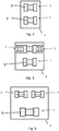
Figuren 5 bis 9 schematische Draufsichten auf eine Untermasse mit mehreren Schwingungserregern; -
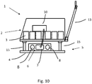
Fig. 10 eine schematische Seitenansicht einer Variante einer erfindungsgemäßen Vibrationsplatte -
Fig. 1 zeigt in stark schematisierter Seitenansicht eine Variante der erfindungsgemäßen Vibrationsplatte (1) mit einer Obermasse (2) und einer Untermasse (5). Die Obermasse (2) umfasst einen Tragrahmen (11) welcher mit einer Trägerplatte (12) verbunden ist. Ferner umfasst die Obermasse im gezeigten Ausführungsbeispiel mindestens ein Energiespeicherelement (3) und eine elektronische Steuerung (10), welche am Tragrahmen (11) angeordnet sind. Ferner umfasst die Obermasse (2) eine Bewässerungsvorrichtung (14) und einen Führungsbügel oder Deichsel (13) mittels welcher ein Bediener die Vibrationsplatte steuern kann. - An der Deichsel (13) ist mindestens ein Bedienelement angeordnet, mittels welchem ein Bediener die Funktion der Vibrationsplatte steuern und/oder regeln kann, d.h. insbesondere die Vibrationsplatte ein- und ausschalten kann.
- Die Deichsel (13) ist vibrationsentkoppelt an der Obermasse (2) angeordnet, so dass schädliche Vibrationen nur verringert an die Deichsel und damit auf einen Bediener übertragen werden.
- Die Bewässerungsvorrichtung (14) umfasst einen Behälter zur Aufnahme von Wasser, welches im Betrieb der Vibrationsplatte aus einem kontrolliert verschließbaren und zu öffnenden Auslauf auf den zu verdichtenden Boden abgegeben werden kann. Dies ist insbesondere bei der Verdichtung von Teer vorteilhaft, um ein Haften der Vibrationsplatte auf dem Teer zu vermeiden.
- Die Obermasse ist mittels Dämpfungselementen (15) mit der Untermasse (5) verbunden. Die Untermasse (5) umfasst eine Bodenkontaktplatte (4), auf welcher sich die Vibrationsplatte (1) über den zu verdichtenden Boden bewegt und auf diesen einwirkt. Ferner umfasst die Untermasse (5) eine Schwingungserregereinrichtung (6) welche mechanische Schwingungen erzeugt und auf die Bodenkontaktplatte (4) überträgt, mit welcher sie verbunden ist.
- Im gezeigten Ausführungsbeispiel der
Figur 1 ist das Energiespeicherelement (3) schwingungsgedämpft an der Obermasse (2) angeordnet. Hierzu ist das Energiespeicherelement (3) an einem Halter (16) angeordnet, welcher schwingungsgedämpft mit der Obermasse (2) verbunden ist. Dies kann durch eine Befestigung mittels Gummipuffern oder mittels eines Drehgelenks erreicht werden. Alternativ kann das Energiespeicherelement (3) auch mittels Schwingungsdämpfern wie z.B. Gummipuffern mit der Obermasse in Kontakt stehen. In einer Variante kann auch die elektronische Steuerung (10) schwingungsgedämpft an der Obermasse (2) angeordnet sein, beispielsweise indem diese ebenfalls am Halter (16) angeordnet ist. - Die elektronische Steuerung (10) dient dazu, die Schwingungserregereinrichtung (6) zu steuern und/oder zu regeln. Die elektronische Steuerung (10) ist dazu ausgelegt, den Elektromotor (7) der Schwingungserregereinrichtung (6) zu beeinflussen und einzustellen, d.h. insbesondere dessen Drehzahl und Drehrichtung einzustellen und zu variieren. Sofern eine erfindungsgemäße Ausführungsform eine Schwingungserregereinrichtung (6) mit mehreren Elektromotoren vorsieht, ist die elektronische Steuerung (10) dazu ausgelegt, die jeweiligen Elektromotoren (7) unabhängig voneinander einzustellen und zu beeinflussen. In einer Variante ist es auch möglich einen oder mehrere Elektromotoren (7) in Abhängigkeit vom Zustand eines oder mehrerer anderer Elektromotoren (7) anzusteuern. So kann beispielsweise die Drehzahl und/oder Drehrichtung eines ersten Elektromotors (7) als Referenz für einen weiteren Elektromotor (7) dienen, an Hand dessen dann der weitere Elektromotor (7) eingestellt wird.
- Ein Elektromotor (7) bildet zusammen der zugeordneten bzw. den zugeordneten Unwuchmassen (8) einen sogenannten Erreger oder Unwuchterreger.
-
Figur 2 zeigt eine beispielhafte Schwingungserregereinrichtung (6). Die Schwingungserregereinrichtung (6) umfasst einen Elektromotor (7) mittels welchem mindestens eine - Unwuchtmasse (8) in Rotation versetzt werden kann. Hierzu ist die Unwuchtmasse (8) bevorzugt mit der Motorwelle (9) des Elektromotors (7) verbunden. Bevorzugt ist der Elektromotor (7) zwischen zwei Unwuchtmassen (8) angeordnet, so dass dieser zentral und axial zwischen den Unwuchtmassen (8) positioniert ist. Die Motorwelle (9) des Elektromotors (7) kann zu beiden Seiten des Elektromotors aus dem Motorgehäuse herausgeführt sein. An den beiden Enden der Motorwelle können die Unwuchtmassen (8) befestigt sein. Alternativ kann die Motorwelle (9) auch derart ausgestaltet sein, dass die Unwuchtmassen (8) integraler Bestandteil der Motorwelle (9) sind.
- Ferner ist es erfindungsgemäß möglich, die Motorwelle (9) des Elektromotors (7) nur aus einer Seite des Motorgehäuses herausgeführt ist und lediglich eine Unwuchtmasse (8) daran befestigt ist.
- Mit dieser Variante ergibt sich die Möglichkeit, dass zwei Elektromotoren axial zueinander ausgerichtet sind, wobei die Motorwellen (9) der Elektromotoren (7) an den gegenüberliegenden, jeweils den Motoren abgewandten Seiten aus den Motorgehäusen herausgeführt sind, wobei an jeder Motorwelle jeweils eine Unwuchtmasse (8) angeordnet ist. Die Elektromotoren können auf diese Weise unabhängig voneinander angesteuert werden und mittels unterschiedlicher Drehrichtung und/oder Drehzahl unterschiedliche Fliehkräfte auf die Untermasse aufbringen, was verschiedene Fahrmanöver ermöglicht.
- Die Schwingungserregereinrichtung (6) ist antriebsmäßig mechanisch autark von der Obermasse (2), d.h. der Schwingungserregereinrichtung wird lediglich elektrische Energie zugeführt. Der Elektromotor (7) erzeugt aus der elektrischen Energie die mechanische Kraft um die Unwuchtmasse(n) (8) anzutreiben. D.h. der Schwingungserregereinrichtung wird lediglich elektrische Energie zugeführt, und sie ist nicht mit der Obermasse mittels eines Riementriebs oder einem hydraulischen System verbunden.
- Zur Zuführung der elektrischen Energie ist der Elektromotor (7) mit einem elektrischen Kabel, welches in den Figuren nicht gezeigt ist, mit der Obermasse verbunden.
-
Figur 3 zeigt eine stark schematisierte Draufsicht auf eine Bodenkontaktplatte (4) mit einer Schwingungserregereinrichtung (6). Die Schwingungserregereinrichtung (6) ist auf der Bodenkontaktplatte (4) angeordnet und mit dieser fest verbunden. Die Schwingungserregereinrichtung (6) ist in Längsrichtung zentral, d.h. mittig der Bodenkontaktplatte (4) angeordnet, wobei die Motorwelle quer zur Längsrichtung der Vibrationsplatte verläuft.. Die Längsrichtung bestimmt sich dabei durch die Bewegungsrichtung der Vibrationsplatte im Betrieb. - Ferner ist die Schwingungserregereinrichtung (6) in einer vorderen Hälfte der Bodenkontaktplatte (4) angeordnet. Diese Positionierung verleiht der Vibrationsplatte (1) die beste Bewegungseigenschaft. Besonders bevorzugt ist die Schwingungserregereinrichtung (6) in einem vorderen Drittel der Bodenkontaktplatte (4) angeordnet. Die Vibrationsplatte (1) kann sich bei Nutzung einer
- Schwingungserregereinrichtung (6) lediglich in eine Richtung bewegen. Die Rotation der Unwuchtmassen (8) bewirkt eine Beschleunigung der Vibrationsplatte (1) nach vorne und oben. Die Bodenkontaktplatte (4) verliert deshalb im Bereich der Schwingungserregereinrichtung (6) kurzzeitig den Bodenkontakt und beschleunigt die Vibrationsplatte (1) nach vorne. Die Vibrationsplatte (1) wird deshalb sozusagen mittels der Schwingungserregereinrichtung (6) über den Boden geschleppt, weshalb man bei Vibrationsplatten dieser Bauart von Schleppschwingern spricht. Derartige Schleppschwinger ermöglichen jedoch lediglich eine Vorwärtsfahrt der Vibrationsplatte (1). Als Vorwärtsrichtung bzw. vorderes Ende der Vibrationsplatte ist die Richtung gemeint, die gegenüber dem Ende der Vibrationsplatte (1) mit dem Führungsbügel (13) liegt. Anders ausgedrückt, bewegt sich die Vibrationsplatte (1) in Vorwärtsrichtung vom Bediener weg. Diese Definition gilt für alle Ausführungsbeispiele dieser Anmeldung.
-
Figur 4 zeigt eine Variante der Vibrationsplatte (1) mit zwei Elektromotoren (7) bzw. Unwuchterregern. Dabei ist ein erster Elektromotor (7) in einer ersten Hälfte der Bodenkontaktplatte (4) angeordnet und ein zweiter Elektromotor (7) in einer zweiten Hälfte der Bodenkontaktplatte (4). Die Nutzung von zwei Elektromotoren (7) führt zu einer verbesserten Verdichtungsleistung und einem gleichmäßigeren Bewegungsverhalten der Vibrationsplatte (1). Dabei sind die Motorwellen (9) der beiden Elektromotoren (7) parallel zueinander ausgerichtet und verlaufen quer zur Längsachse der Vibrationsplatte. - Eine Vibrationsplatte (1) dieser Bauart kann nicht nur lediglich vorwärts sondern auch rückwärtsfahren und im Stand rütteln. Die technischen Grundprinzipien hierzu sind aus dem Stand der Technik bekannt, weshalb hierauf nicht näher eingegangen werden soll.
- Durch die jeweilige Einstellung und Ausrichtung der jeweiligen Unwuchtmassen und damit der resultierenden Fliehkräfte der beiden Elektromotoren (7) kann entweder eine Vorwärtsfahrt, eine Rückwärtsfahrt oder eine Standrüttlung eingestellt werden. Darüber hinaus kann auch die Bewegungsgeschwindigkeit zwischen einer maximalen Vorwärtsgeschwindigkeit und einer maximalen Rückwärtsgeschwindigkeit stufenlos angepasst werden. Dies wird mittels der elektronischen Steuerung erreicht, welche die Elektromotoren (7) unabhängig voneinander ansteuern und einstellen kann.
- Bei Rückwärtsfahrt bewegt sich die Vibrationsplatte (1) in Richtung auf den Bediener zu, d.h. in Richtung des Endes der Vibrationsplatte an welchem der Führungsbügel (13) angeordnet ist.
- Eine weitere Variante ist in
Figur 5 gezeigt, wobei zusätzlich zu den beiden Elektromotoren (7) wie inFigur 4 gezeigt noch mindestens eine weiterer Elektromotor (7) auf der Bodenkontaktplatte (4) angeordnet ist. Dabei sind zwei Elektromotoren (7) mit Motorwellen (9) quer zur Längsachse der Vibrationsplatte (1) angeordnet und mindestens ein weiterer Elektromotor (7) mit der Motorwelle längs, d.h. parallel zur Längsachse angeordnet. Im gezeigten Ausführungsbeispiel sind zwei Elektromotoren (7) mit den Motorwellen parallel zur Längsachse ausgerichtet. - Mittels dieser Anordnung ist es möglich, die Vibrationsplatte (1) richtungssteuerbar auszugestalten. Sofern im Folgenden von der Richtungssteuerung gesprochen wird, ist eine Drehung der Vibrationsplatte (1) um die Hochachse gemeint. Die Vibrationsplatte (1) kann in diesem Fall nicht nur vorwärts und rückwärts, sondern beispielsweise auch nach links und rechts gesteuert werden. Hierzu werden die Drehrichtungen und Drehzahlen der längs zur Längsachse ausgerichteten Elektromotoren (7) dem jeweiligen Fahrtwunsch des Bedieners eingestellt, so dass entsprechende Fliehkräfte erzeugt werden, die die Vibrationsplatte (1) in die gewünschte Richtung bewegen. Auch hier ist die elektronische Steuerung entsprechend ausgestaltet um die jeweilige Zahl an Elektromotoren (7) einzeln und unabhängig voneinander anzusteuern.
- Eine weitere Möglichkeit zur Richtungssteuerung einer Vibrationsplatte (1) ergibt sich durch die Bauweise der Variante wie sie in
Figur 6 gezeigt ist. Hier sind drei Elektromotoren (7) auf der Bodenkontaktplatte (4) angeordnet. Dabei sind zwei Elektromotoren (7) axial zueinander ausgerichtet. Wird in einem der axial ausgerichteten Elektromotoren (7) eine höhere Fliehkraft, d.h. Drehzahl eingestellt als in der anderen axial ausgerichteten Elektromotoren (7) bewegt sich die Vibrationsplatte in dessen Richtung. Sofern beide axial ausgerichteten Elektromotoren (7) in gleiche Drehrichtung und mit gleicher Drehzahl laufen ergibt sich eine Vorwärtsfahrt. - Eine weitere Möglichkeit zur Richtungssteuerung einer Vibrationsplatte (1) ergibt sich durch die Bauweise der Variante wie sie in
Figur 7 gezeigt ist. Hier sind drei Elektromotoren (7) auf der Bodenkontaktplatte (4) angeordnet. Dabei sind zwei Elektromotoren (7) in einem Winkel zueinander angeordnet. D.h. die durch die Motorwellen (9) gebildeten Motorachsen (17) der Elektromotoren (7) schneiden sich. Durch die voneinander abweichende Einstellung der Drehzahlen oder auch der Drehrichtung kann eine Kurvenfahrt, d.h. Drehung um die Hochachse der Vibrationsplatte eingestellt werden. - Ferner ist auch eine Richtungssteuerung mit der Bauweise nach
Figur 8 möglich. Dabei werden im gezeigten Ausführungsbeispiel vier Elektromotoren (7) auf der Bodenkontaktplatte (4) angeordnet. Dabei sind jeweils zwei Elektromotoren (7) axial zueinander ausgerichtet. Gestaffelt vor bzw. dahinter sind nochmals zwei Elektromotoren (7) axial zueinander ausgerichtet. Bei Ansteuerung einer oder beider Elektromotoren (7) zu einer Seite der Längsachse der Vibrationsplatte ergibt sich eine Lenkbewegung bzw. Drehung um die Hochachse. Die Drehbewegung kann verstärkt werden, indem die die beiden Elektromotoren (7) zur anderen Seite der Längsachse in die entgegen gesetzte Richtung drehen. - Alternativ zur Bauweise nach
Figur 8 ist auch eine Anordnung der Elektromotoren (7) wie inFigur 9 gezeigt möglich. Die Elektromotoren (7) sind dabei derart winklig zueinander angeordnet, dass sich die Motorachse (17) eines Elektromotors (7) mit den Motorachsen (17) zweier anderer Elektromotoren (7) schneidet. Die Elektromotoren sind also alle in einem Winkel zur Längsachse der Vibrationsplatte (1) angeordnet, d.h. derart angeordnet, dass sich die Motorachsen (17) aller Elektromotoren mit der Längsachse der Vibrationsplatte (1) schneiden. Bevorzugt liegt der Schnittpunkt der Motorachsen (17) zweier Elektromotoren (7) auf der Längsachse der Vibrationsplatte (1). - Die Anordnung kann so gewählt werden, dass mindestens zwei der Elektromotoren (7) spiegelbildlich zur Längsachse angeordnet sind. Bevorzugt sind vier Elektromotoren (7) spiegelbildlich zur Längsachse angeordnet.
- Eine solche Anordnung bietet Vorteile hinsichtlich des Geradeauslaufs der Vibrationsplatte und verbessert zudem die Lenkbarkeit, d.h. die Drehung um die Hochachse.
- Eine weitere Variante zum Aufbau einer erfindungsgemäßen Vibrationsplatte ist in
Figur 10 gezeigt. Darin ist das Energiespeicherelement (3) aus einer Vielzahl einzelner Akkumulatoren gebildet, die auf der Obermasse (2) angeordnet und miteinander verschaltet sind. Zur Steuerung des bzw. der Motoren ist eine elektronische Steuerung (10) vorgesehen. Im gezeigten Ausführungsbeispiel ist die elektronische Steuerung (10) auf der Obermasse (2) angeordnet. Es ist jedoch generell, d.h. unabhängig vom gezeigten Ausführungsbeispiel, möglich die elektronische Steuerung (10) auch auf der Untermasse (5) anzuordnen. - Im gezeigten Ausführungsbeispiel ist die Schwingungserregereinrichtung (6) mit lediglich einem Elektromotor (7) aufgebaut, der zwei Unwuchtmassen (8) antreibt.
- Generell ist es möglich, d.h. unabhängig von den vorgestellten Ausführungsformen, das Energiespeicherelement aus einzelnen Akkuzellen zu bilden. Die Akkuzellen können einzeln austauschbar sein.
- Ferner besteht die Möglichkeit auf der Vibrationsplatte (1) eine elektronisches Lademodul für die Ladung des Energiespeicherelements (3) vorzusehen. Damit wird die Ladung des Energiespeichers direkt auf der Vibrationsplatte (1) ermöglicht. Es ist damit nicht notwendig den Energiespeicher zu entnehmen und zum Lademodul zu transportieren. Das Lademodul kann mit der elektronischen Steuerung baulich integriert sein.
- Die angesprochenen Merkmale der Erfindung sind nicht auf die in den Figuren gezeigten Kombinationen an Merkmalen eingeschränkt, sondern können beliebig miteinander kombiniert werden.
Claims (9)
- Vibrationsplatte (1) zur Bodenverdichtung, mit
einer Obermasse (2) an welcher mindestens ein Energiespeicherelement (3) angeordnet ist, einer mit der Obermasse (2) elastisch gekoppelten, wenigstens eine Bodenkontaktplatte (4) aufweisenden Untermasse (5), und mit
einer die Bodenkontaktplatte (4) beaufschlagenden Schwingungserregereinrichtung (6), wobei
die Schwingungserregereinrichtung (6) an der Untermasse (5) angeordnet ist und wenigstens einen Elektromotor (7) aufweist, welcher mindestens eine drehbar gelagerte Unwuchtmasse (8) drehend antreibt und welcher mittels der elektrischen Energie des mindestens einen Energiespeicherelements (3) antreibbar ist;
dadurch gekennzeichnet, dass
das Energiespeicherelement (3) an der Obermasse (2) schwingungsentkoppelt angeordnet ist. - Vibrationsplatte (1) nach Anspruch 1, wobei
sich eine Welle (9) des Elektromotors (7) quer zu einer Längsachse der Vibrationsplatte erstreckt - Vibrationsplatte (1) nach Anspruch 1 oder 2, wobei
die Schwingungserregereinrichtung (6) einen Elektromotor (7) mit zwei Unwuchtmassen (8) aufweist, wobei der Elektromotor (7) axial zwischen den beiden Unwuchtmassen (8) angeordnet ist. - Vibrationsplatte (1) nach einem der vorstehenden Ansprüche, wobei der mindestens eine Elektromotor (7) ein bürstenloser Elektromotor (7) ist, insbesondere ein BLDC-Motor, ein SR-Motor oder Asynchron-Motor.
- Vibrationsplatte (1) nach einem der vorstehenden Ansprüche, wobei die Schwingungserregereinrichtung (6) mindestens zwei Elektromotoren (7) mit jeweils zugeordneten Unwuchtmassen (8) aufweist, wobei die Elektromotoren (7) samt zugehöriger Unwuchtmassen (8) räumlich getrennt voneinander auf der Untermasse (8) angeordnet sind.
- Vibrationsplatte (1) nach Anspruch 5, wobei
die mindestens zwei Elektromotoren (7) entlang einer Längsachse der Vibrationsplatte gestaffelt angeordnet sind. - Vibrationsplatte (1) nach einem der vorstehenden Ansprüche, wobei die Vibrationsplatte eine elektronische Steuerung (10) aufweist, welche die Drehrichtung und/oder Drehgeschwindigkeit des mindestens einen Elektromotors (7) steuert und/oder regelt.
- Vibrationsplatte (1) nach Anspruch 7, wobei
die elektronische Steuerung (10) dazu ausgelegt ist, die Drehrichtung und Drehgeschwindigkeit von mindestens zwei Elektromotoren (7) zu steuern und/oder zu regeln und unabhängig voneinander einzustellen. - Vibrationsplatte (1) nach einem der Ansprüche 7 oder 8, wobei die elektronische Steuerung (10) an der Untermasse (5) angeordnet ist.
Applications Claiming Priority (1)
| Application Number | Priority Date | Filing Date | Title |
|---|---|---|---|
| DE102017121177.2A DE102017121177A1 (de) | 2017-09-13 | 2017-09-13 | Bodenverdichtungsvorrichtung |
Publications (2)
| Publication Number | Publication Date |
|---|---|
| EP3456879A1 EP3456879A1 (de) | 2019-03-20 |
| EP3456879B1 true EP3456879B1 (de) | 2021-05-19 |
Family
ID=63407100
Family Applications (1)
| Application Number | Title | Priority Date | Filing Date |
|---|---|---|---|
| EP18190928.4A Active EP3456879B1 (de) | 2017-09-13 | 2018-08-27 | Bodenverdichtungsvorrichtung |
Country Status (5)
| Country | Link |
|---|---|
| US (1) | US10344439B2 (de) |
| EP (1) | EP3456879B1 (de) |
| CN (1) | CN109487779B (de) |
| DE (1) | DE102017121177A1 (de) |
| ES (1) | ES2883654T3 (de) |
Cited By (3)
| Publication number | Priority date | Publication date | Assignee | Title |
|---|---|---|---|---|
| EP4269696A1 (de) | 2022-04-29 | 2023-11-01 | Ammann Schweiz AG | Bodenverdichtungsvorrichtung |
| DE202022002915U1 (de) | 2022-04-29 | 2024-01-15 | Ammann Schweiz Ag | Bodenverdichtungsvorrichtung |
| EP4481121A1 (de) * | 2023-06-20 | 2024-12-25 | Hilti Aktiengesellschaft | Rüttelplatte zum verdichten von erde, boden oder untergrund, sowie verfahren zu deren betrieb und system |
Families Citing this family (19)
| Publication number | Priority date | Publication date | Assignee | Title |
|---|---|---|---|---|
| WO2020202573A1 (ja) * | 2019-04-05 | 2020-10-08 | 本田技研工業株式会社 | 地固め装置 |
| DE102019110041A1 (de) * | 2019-04-16 | 2020-10-22 | Wacker Neuson Produktion GmbH & Co. KG | Handgeführtes Arbeitsgerät mit entkoppeltem Deichselträger |
| US12139876B2 (en) * | 2019-12-09 | 2024-11-12 | Husqvarna Ab | Compaction machine with electric working assembly |
| DE102020102949A1 (de) * | 2020-02-05 | 2021-08-05 | Wacker Neuson Produktion GmbH & Co. KG | Vibrationsplatte mit Elektroantrieb |
| CN111705598A (zh) * | 2020-06-14 | 2020-09-25 | 陈子寅 | 一种公路工程用路面整平机 |
| EP4179150A4 (de) | 2020-07-07 | 2024-09-04 | Milwaukee Electric Tool Corporation | Plattenverdichter |
| US12065790B2 (en) * | 2020-07-07 | 2024-08-20 | Milwaukee Electric Tool Corporation | Plate compactor |
| US20220064877A1 (en) * | 2020-07-07 | 2022-03-03 | Milwaukee Electric Tool Corporation | Plate compactor |
| US20220010506A1 (en) * | 2020-07-07 | 2022-01-13 | Milwaukee Electric Tool Corporation | Plate compactor |
| JP7228910B2 (ja) * | 2020-08-19 | 2023-02-27 | 三笠産業株式会社 | 振動締固め機 |
| DE102020133340A1 (de) * | 2020-12-14 | 2022-06-15 | Wacker Neuson Produktion GmbH & Co. KG | Bodenverdichtungsvorrichtung zum Verdichten eines Bodenbereiches |
| GB2604347A (en) * | 2021-03-01 | 2022-09-07 | Black & Decker Inc | A compacting power tool |
| WO2022265556A1 (en) | 2021-06-14 | 2022-12-22 | Husqvarna Ab | An electric compactor with battery system redundancy |
| WO2023009800A1 (en) | 2021-07-30 | 2023-02-02 | Milwaukee Electric Tool Corporation | Plate compactor |
| DE102022110564B4 (de) * | 2022-04-29 | 2024-02-29 | Ammann Schweiz Ag | Kühlung einer Bodenverdichtungsvorrichtung |
| EP4635046A1 (de) | 2022-12-13 | 2025-10-22 | Husqvarna AB | Baumaschine mit verbesserter batteriehandhabung |
| US20240229426A1 (en) * | 2023-01-09 | 2024-07-11 | Milwaukee Electric Tool Corporation | Plate compactor |
| DE102024119439B3 (de) * | 2024-07-09 | 2025-09-11 | Inecosys Gmbh | Baumaschine |
| DE102024127906A1 (de) * | 2024-09-26 | 2026-03-26 | Wacker Neuson Produktion GmbH & Co. KG | Vibrationsplatte mit einteiliger Schutzhülle |
Family Cites Families (13)
| Publication number | Priority date | Publication date | Assignee | Title |
|---|---|---|---|---|
| US3339422A (en) * | 1965-03-18 | 1967-09-05 | Petrin Frank | Electric motor driven vibrator and adjusting device therefor |
| US3889263A (en) * | 1973-11-15 | 1975-06-10 | Megapulse Inc | Radio-frequency pulse generation system and method |
| DE19731731A1 (de) * | 1997-07-23 | 1999-02-25 | Wacker Werke Kg | Bodenverdichtungsvorrichtung mit veränderbaren Schwingungseigenschaften |
| DE29804993U1 (de) * | 1998-03-19 | 1998-06-18 | Metz, Bernhard, 06791 Möhlau | Rütteleinrichtung zur Verfestigung des Baugrundes |
| DE19812986C1 (de) * | 1998-03-24 | 1999-11-11 | Masa Ag | Unwuchtrüttler für Steinformmaschinen |
| SE513571C2 (sv) * | 1999-03-18 | 2000-10-02 | Ulf Bertil Andersson | Anordning för alstring av mekaniska vibrationer |
| EP1196309B1 (de) * | 1999-07-27 | 2004-01-14 | Wacker Construction Equipment AG | Bodenverdichtungsvorrichtung mit schwingungsisolierender halterung für eine starterbatterie |
| DE19953553A1 (de) * | 1999-11-08 | 2000-06-21 | Joachim Mozdzanowski | Bodenverdichter mit stufenlos verstellbarer Schwingungsamplitude |
| DE60139985D1 (de) | 2001-06-14 | 2009-11-05 | Swepac Internat Ab | Verdichter mit Vibrationsplatte |
| DE102007018353A1 (de) * | 2007-04-18 | 2008-10-30 | Wacker Construction Equipment Ag | Schwingungserreger für Bodenverdichtungsvorrichtungen |
| DE102011104269A1 (de) * | 2011-06-15 | 2012-12-20 | Wacker Neuson Produktion GmbH & Co. KG | Führungsdeichsel mit Energiespeicher |
| US8484857B2 (en) * | 2011-07-26 | 2013-07-16 | General Electric Company | Component for axially aligning two shafts through intermediary materials |
| US9038491B2 (en) * | 2013-05-06 | 2015-05-26 | Martin Engineering Company | Method of repositioning bearing wear in an industrial eccentric weight vibrator via power inversion and vibrator therefore |
-
2017
- 2017-09-13 DE DE102017121177.2A patent/DE102017121177A1/de active Pending
-
2018
- 2018-08-27 EP EP18190928.4A patent/EP3456879B1/de active Active
- 2018-08-27 ES ES18190928T patent/ES2883654T3/es active Active
- 2018-09-12 US US16/129,083 patent/US10344439B2/en active Active
- 2018-09-12 CN CN201811060761.0A patent/CN109487779B/zh active Active
Non-Patent Citations (1)
| Title |
|---|
| None * |
Cited By (6)
| Publication number | Priority date | Publication date | Assignee | Title |
|---|---|---|---|---|
| EP4269696A1 (de) | 2022-04-29 | 2023-11-01 | Ammann Schweiz AG | Bodenverdichtungsvorrichtung |
| DE102022110562A1 (de) | 2022-04-29 | 2023-11-02 | Ammann Schweiz Ag | Bodenverdichtungsvorrichtung |
| DE202022002915U1 (de) | 2022-04-29 | 2024-01-15 | Ammann Schweiz Ag | Bodenverdichtungsvorrichtung |
| DE102022110562B4 (de) | 2022-04-29 | 2024-02-15 | Ammann Schweiz Ag | Bodenverdichtungsvorrichtung |
| EP4481121A1 (de) * | 2023-06-20 | 2024-12-25 | Hilti Aktiengesellschaft | Rüttelplatte zum verdichten von erde, boden oder untergrund, sowie verfahren zu deren betrieb und system |
| EP4481120A1 (de) * | 2023-06-20 | 2024-12-25 | Hilti Aktiengesellschaft | Rüttelplatte zum verdichten von erde, boden oder untergrund, sowie verfahren zu deren betrieb und system |
Also Published As
| Publication number | Publication date |
|---|---|
| US20190078282A1 (en) | 2019-03-14 |
| EP3456879A1 (de) | 2019-03-20 |
| US10344439B2 (en) | 2019-07-09 |
| CN109487779B (zh) | 2022-01-07 |
| ES2883654T3 (es) | 2021-12-09 |
| DE102017121177A1 (de) | 2019-03-28 |
| CN109487779A (zh) | 2019-03-19 |
Similar Documents
| Publication | Publication Date | Title |
|---|---|---|
| EP3456879B1 (de) | Bodenverdichtungsvorrichtung | |
| EP0756656B1 (de) | Maschine zum bearbeiten von fahrbahnen | |
| EP3725949B1 (de) | Handgeführtes arbeitsgerät mit entkoppeltem deichselträger | |
| DE3873164T2 (de) | Strassenkehrmaschine mit kehrrichtauflese- und transportvorrichtung. | |
| DE112016000636T5 (de) | Schwingungsvorrichtung für Vibrationsverdichter | |
| EP1893819B1 (de) | Vibrationsplatte mit individuell einstellbaren schwingungserregern | |
| DE102020102949A1 (de) | Vibrationsplatte mit Elektroantrieb | |
| EP3901373B1 (de) | Wechselaggregat zur texturierenden bodenoberflächenbearbeitung und strassenbaumaschine mit einem solchen wechselaggregat | |
| EP1727940B1 (de) | Bodenverdichtungsvorrichtung | |
| EP1893354A1 (de) | Vibrationsplatte mit winklig angeordneten unwuchtwellen | |
| DE102022127864B4 (de) | Schwingungserzeuger | |
| DE10241200A1 (de) | Schwingungserreger für Bodenverdichtungsgeräte | |
| EP4563750A1 (de) | Bodenverdichtungsgerät mit adaptivem erreger | |
| EP4481121A1 (de) | Rüttelplatte zum verdichten von erde, boden oder untergrund, sowie verfahren zu deren betrieb und system | |
| EP4495326A1 (de) | Bodenverdichtungsvorrichtung und phasenverstellbarer unwuchterreger mit zwei angetriebenen wellen | |
| EP3901372A1 (de) | Bodenverdichtungsvorrichtung mit elektrisch betriebenem radsatz | |
| DE102017009894A1 (de) | Vorrichtung zum Antreiben einer Fräswalze sowie Verfahren zum Antreiben einer Fräswalze | |
| DE102006041784A1 (de) | Schwingungserreger | |
| DE102008006748B4 (de) | Unsymmetrischer Schwingungserreger für eine Vibrationsplatte | |
| EP3705683B1 (de) | Horizontalbohranlage | |
| EP3876692B1 (de) | Landwirtschaftliche vorrichtung zur bodenbearbeitung | |
| WO2009121606A1 (de) | Vibrationsplatte mit riemenantrieb | |
| DE4021278A1 (de) | Vibrationsantrieb | |
| WO2024079035A1 (de) | Baumaschine zum fördern von dickstoff | |
| EP3184695A1 (de) | Bodenverdichtungsbandage und baumaschine zur bodenverdichtung |
Legal Events
| Date | Code | Title | Description |
|---|---|---|---|
| PUAI | Public reference made under article 153(3) epc to a published international application that has entered the european phase |
Free format text: ORIGINAL CODE: 0009012 |
|
| STAA | Information on the status of an ep patent application or granted ep patent |
Free format text: STATUS: THE APPLICATION HAS BEEN PUBLISHED |
|
| AK | Designated contracting states |
Kind code of ref document: A1 Designated state(s): AL AT BE BG CH CY CZ DE DK EE ES FI FR GB GR HR HU IE IS IT LI LT LU LV MC MK MT NL NO PL PT RO RS SE SI SK SM TR |
|
| AX | Request for extension of the european patent |
Extension state: BA ME |
|
| STAA | Information on the status of an ep patent application or granted ep patent |
Free format text: STATUS: REQUEST FOR EXAMINATION WAS MADE |
|
| 17P | Request for examination filed |
Effective date: 20190918 |
|
| RBV | Designated contracting states (corrected) |
Designated state(s): AL AT BE BG CH CY CZ DE DK EE ES FI FR GB GR HR HU IE IS IT LI LT LU LV MC MK MT NL NO PL PT RO RS SE SI SK SM TR |
|
| STAA | Information on the status of an ep patent application or granted ep patent |
Free format text: STATUS: EXAMINATION IS IN PROGRESS |
|
| 17Q | First examination report despatched |
Effective date: 20200213 |
|
| GRAP | Despatch of communication of intention to grant a patent |
Free format text: ORIGINAL CODE: EPIDOSNIGR1 |
|
| STAA | Information on the status of an ep patent application or granted ep patent |
Free format text: STATUS: GRANT OF PATENT IS INTENDED |
|
| INTG | Intention to grant announced |
Effective date: 20201211 |
|
| GRAS | Grant fee paid |
Free format text: ORIGINAL CODE: EPIDOSNIGR3 |
|
| GRAA | (expected) grant |
Free format text: ORIGINAL CODE: 0009210 |
|
| STAA | Information on the status of an ep patent application or granted ep patent |
Free format text: STATUS: THE PATENT HAS BEEN GRANTED |
|
| AK | Designated contracting states |
Kind code of ref document: B1 Designated state(s): AL AT BE BG CH CY CZ DE DK EE ES FI FR GB GR HR HU IE IS IT LI LT LU LV MC MK MT NL NO PL PT RO RS SE SI SK SM TR |
|
| REG | Reference to a national code |
Ref country code: GB Ref legal event code: FG4D Free format text: NOT ENGLISH |
|
| REG | Reference to a national code |
Ref country code: CH Ref legal event code: EP |
|
| REG | Reference to a national code |
Ref country code: DE Ref legal event code: R096 Ref document number: 502018005297 Country of ref document: DE |
|
| REG | Reference to a national code |
Ref country code: AT Ref legal event code: REF Ref document number: 1394069 Country of ref document: AT Kind code of ref document: T Effective date: 20210615 |
|
| REG | Reference to a national code |
Ref country code: IE Ref legal event code: FG4D Free format text: LANGUAGE OF EP DOCUMENT: GERMAN |
|
| REG | Reference to a national code |
Ref country code: SE Ref legal event code: TRGR |
|
| REG | Reference to a national code |
Ref country code: LT Ref legal event code: MG9D |
|
| REG | Reference to a national code |
Ref country code: NL Ref legal event code: MP Effective date: 20210519 |
|
| PG25 | Lapsed in a contracting state [announced via postgrant information from national office to epo] |
Ref country code: FI Free format text: LAPSE BECAUSE OF FAILURE TO SUBMIT A TRANSLATION OF THE DESCRIPTION OR TO PAY THE FEE WITHIN THE PRESCRIBED TIME-LIMIT Effective date: 20210519 Ref country code: HR Free format text: LAPSE BECAUSE OF FAILURE TO SUBMIT A TRANSLATION OF THE DESCRIPTION OR TO PAY THE FEE WITHIN THE PRESCRIBED TIME-LIMIT Effective date: 20210519 Ref country code: LT Free format text: LAPSE BECAUSE OF FAILURE TO SUBMIT A TRANSLATION OF THE DESCRIPTION OR TO PAY THE FEE WITHIN THE PRESCRIBED TIME-LIMIT Effective date: 20210519 |
|
| PG25 | Lapsed in a contracting state [announced via postgrant information from national office to epo] |
Ref country code: PL Free format text: LAPSE BECAUSE OF FAILURE TO SUBMIT A TRANSLATION OF THE DESCRIPTION OR TO PAY THE FEE WITHIN THE PRESCRIBED TIME-LIMIT Effective date: 20210519 Ref country code: NO Free format text: LAPSE BECAUSE OF FAILURE TO SUBMIT A TRANSLATION OF THE DESCRIPTION OR TO PAY THE FEE WITHIN THE PRESCRIBED TIME-LIMIT Effective date: 20210819 Ref country code: LV Free format text: LAPSE BECAUSE OF FAILURE TO SUBMIT A TRANSLATION OF THE DESCRIPTION OR TO PAY THE FEE WITHIN THE PRESCRIBED TIME-LIMIT Effective date: 20210519 Ref country code: PT Free format text: LAPSE BECAUSE OF FAILURE TO SUBMIT A TRANSLATION OF THE DESCRIPTION OR TO PAY THE FEE WITHIN THE PRESCRIBED TIME-LIMIT Effective date: 20210920 Ref country code: RS Free format text: LAPSE BECAUSE OF FAILURE TO SUBMIT A TRANSLATION OF THE DESCRIPTION OR TO PAY THE FEE WITHIN THE PRESCRIBED TIME-LIMIT Effective date: 20210519 Ref country code: IS Free format text: LAPSE BECAUSE OF FAILURE TO SUBMIT A TRANSLATION OF THE DESCRIPTION OR TO PAY THE FEE WITHIN THE PRESCRIBED TIME-LIMIT Effective date: 20210919 Ref country code: GR Free format text: LAPSE BECAUSE OF FAILURE TO SUBMIT A TRANSLATION OF THE DESCRIPTION OR TO PAY THE FEE WITHIN THE PRESCRIBED TIME-LIMIT Effective date: 20210820 |
|
| REG | Reference to a national code |
Ref country code: ES Ref legal event code: FG2A Ref document number: 2883654 Country of ref document: ES Kind code of ref document: T3 Effective date: 20211209 |
|
| PG25 | Lapsed in a contracting state [announced via postgrant information from national office to epo] |
Ref country code: NL Free format text: LAPSE BECAUSE OF FAILURE TO SUBMIT A TRANSLATION OF THE DESCRIPTION OR TO PAY THE FEE WITHIN THE PRESCRIBED TIME-LIMIT Effective date: 20210519 |
|
| PG25 | Lapsed in a contracting state [announced via postgrant information from national office to epo] |
Ref country code: DK Free format text: LAPSE BECAUSE OF FAILURE TO SUBMIT A TRANSLATION OF THE DESCRIPTION OR TO PAY THE FEE WITHIN THE PRESCRIBED TIME-LIMIT Effective date: 20210519 Ref country code: CZ Free format text: LAPSE BECAUSE OF FAILURE TO SUBMIT A TRANSLATION OF THE DESCRIPTION OR TO PAY THE FEE WITHIN THE PRESCRIBED TIME-LIMIT Effective date: 20210519 Ref country code: RO Free format text: LAPSE BECAUSE OF FAILURE TO SUBMIT A TRANSLATION OF THE DESCRIPTION OR TO PAY THE FEE WITHIN THE PRESCRIBED TIME-LIMIT Effective date: 20210519 Ref country code: SK Free format text: LAPSE BECAUSE OF FAILURE TO SUBMIT A TRANSLATION OF THE DESCRIPTION OR TO PAY THE FEE WITHIN THE PRESCRIBED TIME-LIMIT Effective date: 20210519 Ref country code: SM Free format text: LAPSE BECAUSE OF FAILURE TO SUBMIT A TRANSLATION OF THE DESCRIPTION OR TO PAY THE FEE WITHIN THE PRESCRIBED TIME-LIMIT Effective date: 20210519 Ref country code: EE Free format text: LAPSE BECAUSE OF FAILURE TO SUBMIT A TRANSLATION OF THE DESCRIPTION OR TO PAY THE FEE WITHIN THE PRESCRIBED TIME-LIMIT Effective date: 20210519 |
|
| REG | Reference to a national code |
Ref country code: DE Ref legal event code: R097 Ref document number: 502018005297 Country of ref document: DE |
|
| PLBE | No opposition filed within time limit |
Free format text: ORIGINAL CODE: 0009261 |
|
| STAA | Information on the status of an ep patent application or granted ep patent |
Free format text: STATUS: NO OPPOSITION FILED WITHIN TIME LIMIT |
|
| PG25 | Lapsed in a contracting state [announced via postgrant information from national office to epo] |
Ref country code: MC Free format text: LAPSE BECAUSE OF FAILURE TO SUBMIT A TRANSLATION OF THE DESCRIPTION OR TO PAY THE FEE WITHIN THE PRESCRIBED TIME-LIMIT Effective date: 20210519 |
|
| REG | Reference to a national code |
Ref country code: BE Ref legal event code: MM Effective date: 20210831 |
|
| 26N | No opposition filed |
Effective date: 20220222 |
|
| PG25 | Lapsed in a contracting state [announced via postgrant information from national office to epo] |
Ref country code: IS Free format text: LAPSE BECAUSE OF FAILURE TO SUBMIT A TRANSLATION OF THE DESCRIPTION OR TO PAY THE FEE WITHIN THE PRESCRIBED TIME-LIMIT Effective date: 20210919 Ref country code: LU Free format text: LAPSE BECAUSE OF NON-PAYMENT OF DUE FEES Effective date: 20210827 Ref country code: AL Free format text: LAPSE BECAUSE OF FAILURE TO SUBMIT A TRANSLATION OF THE DESCRIPTION OR TO PAY THE FEE WITHIN THE PRESCRIBED TIME-LIMIT Effective date: 20210519 |
|
| PG25 | Lapsed in a contracting state [announced via postgrant information from national office to epo] |
Ref country code: IE Free format text: LAPSE BECAUSE OF NON-PAYMENT OF DUE FEES Effective date: 20210827 Ref country code: BE Free format text: LAPSE BECAUSE OF NON-PAYMENT OF DUE FEES Effective date: 20210831 |
|
| PG25 | Lapsed in a contracting state [announced via postgrant information from national office to epo] |
Ref country code: CY Free format text: LAPSE BECAUSE OF FAILURE TO SUBMIT A TRANSLATION OF THE DESCRIPTION OR TO PAY THE FEE WITHIN THE PRESCRIBED TIME-LIMIT Effective date: 20210519 |
|
| PG25 | Lapsed in a contracting state [announced via postgrant information from national office to epo] |
Ref country code: HU Free format text: LAPSE BECAUSE OF FAILURE TO SUBMIT A TRANSLATION OF THE DESCRIPTION OR TO PAY THE FEE WITHIN THE PRESCRIBED TIME-LIMIT; INVALID AB INITIO Effective date: 20180827 |
|
| PG25 | Lapsed in a contracting state [announced via postgrant information from national office to epo] |
Ref country code: MK Free format text: LAPSE BECAUSE OF FAILURE TO SUBMIT A TRANSLATION OF THE DESCRIPTION OR TO PAY THE FEE WITHIN THE PRESCRIBED TIME-LIMIT Effective date: 20210519 |
|
| PG25 | Lapsed in a contracting state [announced via postgrant information from national office to epo] |
Ref country code: TR Free format text: LAPSE BECAUSE OF FAILURE TO SUBMIT A TRANSLATION OF THE DESCRIPTION OR TO PAY THE FEE WITHIN THE PRESCRIBED TIME-LIMIT Effective date: 20210519 |
|
| PG25 | Lapsed in a contracting state [announced via postgrant information from national office to epo] |
Ref country code: MT Free format text: LAPSE BECAUSE OF FAILURE TO SUBMIT A TRANSLATION OF THE DESCRIPTION OR TO PAY THE FEE WITHIN THE PRESCRIBED TIME-LIMIT Effective date: 20210519 |
|
| PGFP | Annual fee paid to national office [announced via postgrant information from national office to epo] |
Ref country code: ES Payment date: 20250917 Year of fee payment: 8 |
|
| PGFP | Annual fee paid to national office [announced via postgrant information from national office to epo] |
Ref country code: DE Payment date: 20250819 Year of fee payment: 8 |
|
| PGFP | Annual fee paid to national office [announced via postgrant information from national office to epo] |
Ref country code: IT Payment date: 20250829 Year of fee payment: 8 |
|
| PGFP | Annual fee paid to national office [announced via postgrant information from national office to epo] |
Ref country code: BG Payment date: 20250821 Year of fee payment: 8 Ref country code: GB Payment date: 20250818 Year of fee payment: 8 |
|
| PGFP | Annual fee paid to national office [announced via postgrant information from national office to epo] |
Ref country code: AT Payment date: 20250819 Year of fee payment: 8 Ref country code: FR Payment date: 20250821 Year of fee payment: 8 |
|
| PGFP | Annual fee paid to national office [announced via postgrant information from national office to epo] |
Ref country code: CH Payment date: 20250901 Year of fee payment: 8 Ref country code: SE Payment date: 20250821 Year of fee payment: 8 |