EP3453974A1 - Kochfeldvorrichtung - Google Patents
Kochfeldvorrichtung Download PDFInfo
- Publication number
- EP3453974A1 EP3453974A1 EP18188933.8A EP18188933A EP3453974A1 EP 3453974 A1 EP3453974 A1 EP 3453974A1 EP 18188933 A EP18188933 A EP 18188933A EP 3453974 A1 EP3453974 A1 EP 3453974A1
- Authority
- EP
- European Patent Office
- Prior art keywords
- hob
- unit
- plate
- heating element
- extension
- Prior art date
- Legal status (The legal status is an assumption and is not a legal conclusion. Google has not performed a legal analysis and makes no representation as to the accuracy of the status listed.)
- Granted
Links
Images


Classifications
-
- F—MECHANICAL ENGINEERING; LIGHTING; HEATING; WEAPONS; BLASTING
- F24—HEATING; RANGES; VENTILATING
- F24C—DOMESTIC STOVES OR RANGES ; DETAILS OF DOMESTIC STOVES OR RANGES, OF GENERAL APPLICATION
- F24C15/00—Details
- F24C15/20—Removing cooking fumes
- F24C15/2042—Devices for removing cooking fumes structurally associated with a cooking range e.g. downdraft
-
- F—MECHANICAL ENGINEERING; LIGHTING; HEATING; WEAPONS; BLASTING
- F24—HEATING; RANGES; VENTILATING
- F24C—DOMESTIC STOVES OR RANGES ; DETAILS OF DOMESTIC STOVES OR RANGES, OF GENERAL APPLICATION
- F24C15/00—Details
- F24C15/10—Tops, e.g. hot plates; Rings
-
- H—ELECTRICITY
- H05—ELECTRIC TECHNIQUES NOT OTHERWISE PROVIDED FOR
- H05B—ELECTRIC HEATING; ELECTRIC LIGHT SOURCES NOT OTHERWISE PROVIDED FOR; CIRCUIT ARRANGEMENTS FOR ELECTRIC LIGHT SOURCES, IN GENERAL
- H05B6/00—Heating by electric, magnetic or electromagnetic fields
- H05B6/02—Induction heating
- H05B6/10—Induction heating apparatus, other than furnaces, for specific applications
- H05B6/12—Cooking devices
- H05B6/1209—Cooking devices induction cooking plates or the like and devices to be used in combination with them
Definitions
- the invention relates to a hob apparatus according to the preamble of claim 1 and a method for operating a hob apparatus according to claim 14.
- a hob device with a cooktop plate and with a trigger unit is already known.
- An impeller of the extraction unit is arranged in an operating state below the hob plate.
- the extraction unit sucks in the operating state by means of the fan in the operating condition resulting vapors from a cooking area through a take-off of the hob plate through.
- the hob plate has a longitudinal extent of 80 cm.
- Embodiments are also known in which a longitudinal extent of the hob plate is greater than 80 cm. For such a cooktop, a large amount of space is necessary, which is why in confined conditions, especially in a cooking space, on a hob, in which a trigger unit is disposed in an installed position below a cooktop plate must be dispensed with.
- the object of the invention is in particular to provide a generic device with improved properties in terms of a construction.
- the object is achieved by the features of claims 1 and 14, while advantageous embodiments and modifications of the invention can be taken from the dependent claims.
- the invention is based on a cooktop device, in particular an induction cooktop device, with at least one cooktop panel and with at least one extraction unit, which has at least one impeller and which by means of the impeller in at least one operating condition resulting vapors from at least one cooking area through at least one Abzugsaus predominantlyung the cooktop plate at least partially sucks.
- a longitudinal extent of the cooktop panel is not more than 75 cm, in particular not more than 70 cm, advantageously not more than 65 cm and preferably not more than 60 cm.
- an optimized and / or improved construction can be achieved.
- a compact design and / or a smaller space requirement can be achieved, in particular with unchanged and advantageously improved performance.
- a trigger unit can be integrated below a hob plate, which can be dispensed in particular to a arranged above the hob extractor hood, resulting in particular to increased comfort for a Contributes to the operator.
- an entire region of the withdrawal recess can be used to extract the vapors produced in the operating state, wherein in particular a reduction of the withdrawal recess by units arranged in the region of the withdrawal recess can be dispensed with.
- a “cooktop device”, in particular an “induction cooktop device”, should in particular be understood as meaning at least one part, in particular a subassembly, of a cooktop, in particular an induction cooktop.
- a “cooktop panel” is to be understood in particular a unit which is provided in at least one operating state for setting up cooking utensils and which is in particular intended to form part of a cooktop outer casing, in particular the cooktop apparatus and / or a cooktop having the cooktop apparatus.
- the hob plate in an installed position forms an operator facing part of the hob outside housing.
- the cooktop panel has all the objects which delimits a cooktop having the cooktop device in an installed position upwards, in particular on an operator-facing side.
- the cooktop panel consists in particular at least for the most part of glass and / or glass ceramic.
- at least to a large extent should be understood in particular to a proportion of at least 70%, in particular at least 80%, advantageously at least 90% and preferably at least 95%.
- a "withdrawal unit” is to be understood in particular a unit which sucks and / or filters vapors produced in the operating state in at least one operating state by means of the impeller, and which, in particular in the operating state by means of the impeller, at least removes these vapors from a cooking area.
- the extraction unit has in particular at least one grease filter unit which, in at least one operating state, at least substantially absorbs dissolved fat particles in the vapors produced in the operating state and / or at least substantially removes them from the vapors.
- the extraction unit has at least one air guiding unit, which in particular defines at least one outlet channel and which, in particular in at least one operating state, connects the cooking area with the fan wheel by means of the outlet channel.
- the withdrawal channel is provided to a line of vapors produced in the operating condition.
- the exhaust duct diverts the vapors generated in the operating condition, at least in large part, in particular, from the cooking area to the impeller.
- An "impeller” is to be understood in particular as meaning a unit which, in at least one operating state, has at least one intake flow for in the operating state Provides resulting vapors and in particular transported away the extracted vapors from the cooking area at least.
- the withdrawal unit could divert the vapors produced in the operating state by means of the impeller from the cooking area and additionally from a cooking space, in particular a kitchen, and feed, for example, at least one exhaust air line.
- the extraction unit could, in particular in the operating state, transport the vapors produced in the operating state by means of the fan wheel from the cooking area into at least one further partial area of the cooking space.
- a “cooking area” is to be understood in particular as a partial area of a cooking space in which a cooking process takes place in the operating state and in which vapors escaping in particular during the cooking process escape from at least one heated cooking utensil and which advantageously extend in an installed position at least to a large extent above the cooking area Hob plate extends.
- a “cooking space” is to be understood, in particular, as meaning a space, in particular a room, in which a cooktop comprising the cooktop device is set up and / or arranged.
- a "withdrawal recess” is to be understood in particular as meaning an opening and / or a hole and / or a recess in the hob plate, through which the fan wheel extracts the vapors from the cooking space in at least one operating state.
- the air-guiding unit defines and / or delimits at least one outlet channel which, in particular in at least one assembled state, connects the extraction recess and the fan wheel to one another.
- the air guide unit is in particular provided to connect the cooking chamber with the impeller by means of the exhaust duct.
- the withdrawal channel is provided to a line of vapors produced in the operating condition.
- the withdrawal recess could be a peripheral recess of the hob plate, which in particular in a main extension plane of the hob plate with respect to a center and / or mathematical center of gravity of Abzugsaus originallyung over an angular range of 330 °, preferably at most 300 °, preferably of at most 270 ° and preferably of at most 240 ° could be surrounded by at least one body of the hob plate.
- the Abzugsaus simplifiedung an inner recess of the cooktop panel, which in particular in a main extension plane of the cooktop considered with respect to a center and / or mathematical center of gravity of Abzugsausappelung over an angular range of at least 270 °, in particular of at least 300 °, preferably of at least 330 ° and preferably of At least 350 ° is surrounded by at least one body of the hob plate.
- a “main extension plane” of an object should be understood to mean, in particular, a plane which is parallel to a largest side surface of a smallest imaginary geometric cuboid which just completely encloses the object, and in particular runs through the center of the cuboid.
- a “longitudinal extent” of an object should be understood to mean, in particular, a length of a longest side of a smallest imaginary geometric cuboid which just completely encloses the object.
- the hob plate could be designed in several parts and in particular have at least two plate elements, which could form an operator facing surface in particular in at least one mounted state and in an installation position, in particular between the plate elements, the Abzugsaus fundamentalung may be formed.
- the cooktop panel has at least one base body with the Abzugsausnaturalung.
- the main body of the hob plate is integrally formed.
- one piece should be understood in particular at least materially connected connected, for example, by a welding process, a gluing process, a Anspritzrea and / or another, the skilled person appear useful process, and / or advantageously formed in one piece, such as by a Manufacture from a casting and / or by a production in a one- or multi-component injection molding process and advantageously from a single blank.
- the hob plate in particular in addition to the base body, at least one frame element, which could be arranged in particular on the base body, and / or at least one coating which could be arranged in particular on the base body, and / or at least one serigraphy, which in particular could be arranged, the base body.
- a high stability can be achieved.
- the withdrawal recess has an extension along the longitudinal extension of the cooktop panel of not more than 120 mm, in particular not more than 110 mm, advantageously not more than 100 mm and preferably not more than 90 mm.
- the withdrawal recess has an extent along the longitudinal extent of the hob plate of at least 20 mm, in particular of at least 30 mm, advantageously of at least 40 mm and preferably of at least 50 mm.
- the deduction recess is in particular free of further structural units, which could be arranged in particular in an area of the withdrawal recess.
- the extraction unit In the operating state, the extraction unit in particular sucks all the vapors produced in the operating state through the extraction recess. As a result, in particular a compact configuration can be achieved.
- the extraction unit could have at least two outlet openings in a region of the withdrawal recess, which could be separated from each other in particular by at least one assembly arranged in the region of the withdrawal recess.
- the assembly arranged in the region of the withdrawal recess could limit a volume of the withdrawal recess which is available for extraction.
- the extraction unit in a region of the AbzugsausNeillung on exactly one exhaust port through which pass in the operating condition vapors.
- a “discharge opening” should in particular be understood to mean an opening and / or recess and / or recess arranged in the region of the withdrawal recess, through which the fan wheel in the operating state in particular sucks the vapors produced in the operating state and through which vapors effectively pass in the operating state ,
- the vent is in particular free of other units that could limit the vent.
- the exhaust port is smaller than the Abzugsaus aloneung. If the withdrawal recess is free of further structural units arranged in the region of the withdrawal recess which could limit the withdrawal opening in particular, the withdrawal opening corresponds to the withdrawal recess.
- a "region" of the withdrawal recess is to be understood in particular as meaning a three-dimensional space which is arranged in at least one mounted state within a plate-like body spanned by the cooking field plate, which in particular comprises the withdrawal recess.
- an entire region of the withdrawal recess can be used to extract the vapors produced in the operating state, wherein in particular a reduction of the withdrawal recess by units arranged in the region of the withdrawal recess can be dispensed with.
- the extraction unit has at least one channel unit which connects the cooking area and the impeller at least in sections and in particular completely with each other.
- the channel unit has a longitudinal extension, which is aligned in particular at least substantially perpendicular to a main extension plane of the hob plate, whereby in particular a substantially vertical extraction of the resulting vapors in the operating condition and / or a short Absaugungsweg can be made possible.
- the fan wheel sucks the vapors produced in the operating state through the channel unit from the cooking area.
- the vapors produced in the operating state in particular pass through the channel unit.
- the channel unit defines a guide path for the vapors produced in the operating state.
- the channel unit is at least partially formed integrally with the cooking field plate, in particular in a region of the Abzugsaus supraung.
- the channel unit has an extension along the longitudinal extension of the cooktop panel of not more than 120 mm, in particular not more than 110 mm, advantageously not more than 100 mm and preferably not more than 90 mm.
- the channel unit has an extension along the longitudinal extent of the hob plate of at least 20 mm, in particular of at least 30 mm, advantageously of at least 40 mm and preferably of at least 50 mm.
- the extraction unit has at least one grease filter unit which has an extension along the longitudinal extent of the hob plate of not more than 120 mm, in particular not more than 110 mm, advantageously not more than 100 mm and preferably not more than 90 mm.
- the grease filter unit has an extent along the longitudinal extent of the hob plate of at least 20 mm, in particular of at least 30 mm, advantageously of at least 40 mm and preferably of at least 50 mm.
- An extension of the grease filter unit along the longitudinal extent of the hob plate is in particular smaller than an extension of the withdrawal recess along the longitudinal extent of the cooking field plate.
- the grease filter unit When viewed perpendicularly on a main extension plane of the hob plate, the grease filter unit is arranged in particular at least partially and advantageously completely overlapping with the Abzugsaus originallyung.
- the grease filter unit is arranged on a main extension plane of the cooking field plate within the extraction recess when viewed perpendicularly.
- the vapors produced in the operating state can be cleaned in particular of dirt particles.
- a high-performance fat filter unit can be provided, which in particular allows a high level of operating comfort.
- the grease filter unit could be arranged, for example, above the channel unit and / or above the withdrawal recess.
- the grease filter unit is disposed within the channel unit.
- the fat filter unit when viewed in at least one cross-sectional plane, has an at least substantially horseshoe-shaped form.
- the cooktop device has at least one heating element, which viewed along the longitudinal extent of the cooktop panel to a length of at least 10%, in particular at least 15%, advantageously at least 20% and preferably at least 25% of a maximum extent of the impeller along the longitudinal extension of the hob plate is arranged overlapping with the impeller.
- a heating element is to be understood as meaning in particular an element which, in the operating state, converts energy, preferably electrical energy, into heat and in particular supplies it to at least one cooking utensil.
- the heating element is designed in particular as an induction heating element and preferably generates an electromagnetic alternating field, in particular with a frequency between 20 kHz and 100 kHz, which is converted in particular in a set up, in particular metallic, preferably ferromagnetic cooking plate by eddy current induction and / or Ummagnetmaschines bine into heat.
- an induction heating element preferably generates an electromagnetic alternating field, in particular with a frequency between 20 kHz and 100 kHz, which is converted in particular in a set up, in particular metallic, preferably ferromagnetic cooking plate by eddy current induction and / or Ummagnetmaschines bine into heat.
- the cooktop device has at least one further heating element which, viewed along the longitudinal extent of the cooktop plate, is arranged on a side of the flue recess opposite the heating element and which, viewed along the longitudinal extent of the cooktop plate, has a distance of not more than 150 mm, in particular of a maximum of 140 mm, advantageously of not more than 130 mm and preferably of not more than 120 mm.
- the further heating element to the heating element along the longitudinal extent of the hob plate considered a distance of at least 30 mm, in particular of at least 40 mm, advantageously at least 50 mm and preferably at least 60 mm.
- the further heating element along the longitudinal extent of the hob plate considered to a length of at least 10%, more preferably at least 20% and preferably at least 20% and preferably at least 25% of a maximum extension of the impeller along the longitudinal extent of the hob overlapping with the impeller arranged.
- the cooktop device has at least one electronic unit which, in the operating state, supplies the heating element and in particular the further heating element and which has at least two subunits which, viewed along the longitudinal extension of the cooktop plate, have a distance of not more than 150 mm, in particular not more than 140 mm , advantageously of not more than 130 mm and preferably not more than 120 mm.
- an "electronic unit” is to be understood, in particular, as an electrical and / or electronic unit which has at least one electrical and / or electronic structural unit, which is preferably designed as a power component.
- the electronic unit has at least one printed circuit board and in particular additionally at least one structural unit, which is arranged in particular at least in an assembled state on the printed circuit board.
- the structural unit could be, for example, at least one inverter and / or at least one control unit and / or at least one cooling unit.
- the electronics unit is provided at least for supplying the heating element, in particular with electrical energy. As a result, it is possible, in particular, to create space for the channel unit, which, in particular, runs perpendicular to a main extension plane of the hob plate between the subunits.
- the cooktop device and, in particular, a cooktop having the cooktop device could be free of a cover unit.
- the withdrawal recess could be arranged in an inaccessible area, in which in particular a cover unit could be dispensed with.
- the extraction recess is advantageously arranged on an area of the hob plate facing and / or accessible to an operator.
- the hob device preferably has at least one cover unit, which conceals the withdrawal recess when viewed perpendicularly onto a main extension plane of the hob plate.
- the cover unit be arranged in an installation position, in particular within the AbzugsausEnglishung and / or in a region of the Abzugsausnaturalung.
- the cover unit In an installed position, the cover unit is arranged in particular above the withdrawal recess and in particular has an extension along the longitudinal extent of the cooktop panel which is larger than an extension of the withdrawal recess along the longitudinal extension of the cooktop panel.
- the cover unit could be designed to be removable, in particular to allow a cleaning of components of the withdrawal unit, which could be arranged in particular in an installed position below the cover unit, in particular the grease filter unit.
- the grease filter unit could be connected to the cover unit and, in particular, be detachable together with the cover unit.
- a particularly advantageous construction can be achieved, in particular, by a method for operating a cooktop device, with a cooktop panel whose longitudinal extension is at most 75 cm, in particular at most 70 cm, advantageously at most 65 cm and preferably at most 60 cm, wherein in at least one operating state vapors at least one cooking area to be sucked through a Abzugsaus fundamentalung the hob plate in an area below the hob plate.
- the hob device should not be limited to the application and embodiment described above.
- the cooktop apparatus may have a number different from a number of individual elements, components and units mentioned herein.
- Fig. 1 shows a hob 56a, which is formed as an induction hob, with a hob device 10a, which is designed as an induction hob device.
- the hob apparatus 10a has a cooktop panel 12a.
- the cooktop panel 12a forms part of a cooktop outer casing, in particular a cooktop outer casing, in particular of the cooktop 56a.
- the hob plate 12a is provided for setting up cooking utensils (not shown).
- the hob device 10a has four heating elements 38a in the present exemplary embodiment. Of multiply existing objects, only one is provided with a reference numeral in the figures.
- the heating elements 38a are arranged in a matrix. In the present embodiment, the heating elements 38a are arranged in a row.
- the hob device 10a has in the present embodiment, four further heating elements 40a.
- the further heating elements 40a are arranged in a matrix. In the present embodiment, the further heating elements 40a are arranged in a row.
- the hob apparatus 10a could have a different number of heating elements 38a and / or other heating elements 40a.
- the hob device 10a could have at least ten, in particular at least twelve and advantageously at least fifteen and preferably a plurality of heating elements 38a and / or at further heating elements 40a.
- Hob device 10a could alternatively have a smaller number of heating elements 38a and / or other heating elements 40a, such as two and / or three and / or four heating elements 38a and / or further heating elements 40a. In the following, only one of the heating elements 38a and one of the further heating elements 40a will be described.
- the heating element 38a is arranged in an installed position below the hob plate 12a.
- the heating element 38a is intended to heat on the hob plate 12a above the heating element 38a set up cooking utensils.
- the heating element 38a is designed as an induction heating element.
- the further heating element 40a is arranged in an installed position below the hob plate 12a.
- the further heating element 40a is provided on the hob plate 12a above the heating element 40a further heated cooking utensils.
- the further heating element 40a is designed as an induction heating element.
- the cooktop apparatus 10a has an operator interface 58a for input and / or selection of operating parameters, for example a heating power and / or a heating power density and / or a heating zone.
- the operator interface 58a is provided for outputting a value of an operating parameter to an operator.
- the hob device 10a has a control unit 60a.
- the control unit 60a is provided to execute actions and / or to change settings in dependence on operating parameters entered via the user interface 58a.
- the control unit 60a controls a supply of energy to the heating element 38a and to the further heating element 40a in a heating operating state.
- the hob device 10a has an outer casing unit 62a (see FIG. Fig. 2 ).
- the outer housing unit 62a forms part of the cooking field outer housing.
- the outer housing unit 62a and the cooktop panel 12a are connected to each other, in particular fastened to each other.
- the outer housing unit 62a and the cooktop panel 12a define a storage space 64a.
- the hob device 10a has a space divider element 66a (cf. Fig. 2 ). In an assembled state, the space divider element 66a is partially fixed to the outer housing unit 62a. In an installed position, the room divider element 66a lies partially on the outer housing unit 62a, in particular on a molding of the outer housing unit 62a and / or on a step of the outer housing unit 62a.
- the divider element 66a divides the storage space 64a into two subspaces.
- a first subspace is arranged in an installed position above the room divider element 66a.
- the first subspace is arranged in an assembled state on one of the cooktop panel 12a facing side of the space divider element 66a.
- the heating element 38a and the further heating element 40a are arranged.
- the room divider element 66a carries in an installed position the heating element 38a and the further heating element 40a to a large extent.
- a second subspace is arranged in an installed position below the space divider element 66a.
- the second subspace is arranged in a mounted state on a side facing away from the cooktop panel 12a of the space divider element 66a.
- the control unit 60a is arranged in the second subspace.
- the room divider element 66a is designed as a shielding element. In one operating state, the divider element 66a shields objects arranged in the second subspace to electromagnetic radiation, which in particular from the heating element 38a and / or from the further heating element 40a emanates substantially.
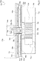
- the hob device 10a has a take-off unit 14a (cf. Fig. 2 ).
- the extraction unit 14a has an impeller 16a. In one operating state, the extraction unit 14a extracts by means of the fan 16a in an operating state resulting vapors from a cooking area 18a through a take-off recess 20a of the hob plate 12a partially from.
- the cooking area 18a is an area which is in an installed position above the cooking plate 12a.
- the fan 16a is arranged in an installed position below the hob plate 12a. In an installed position, the impeller 16a is arranged below the outer housing unit 62a. The impeller 16a is arranged in an installed position below the take-off recess 20a. In an assembled state, an air guiding unit 76a of the drawing unit 14a is fixed to the outer housing unit 62a.
- the cooktop panel 12a has the withdrawal recess 20a.
- the withdrawal recess 20 is formed as an internal recess.
- a main body 24a of the hob plate 12 surrounds the withdrawal recess 20 with respect to a center and / or mathematical center of gravity of the withdrawal recess 20a over an angular range of substantially 360 °.
- the hob plate 12a has the main body 24a with the Abzugsaus originallyung 20a.
- the main body 24a is integrally formed.
- the main body 24a consists to a large extent of glass ceramic.
- the hob plate 12a has a longitudinal extent 22a of substantially 60 cm.
- the main body 24a of the hob plate 12a has an extension along the longitudinal extension 22a of the hob plate 12a of substantially 60 cm.
- the withdrawal recess 20a in the present embodiment has an extension 26a of substantially 68 mm.
- the withdrawal recess 20a is arranged substantially centrally along the longitudinal extent 22a of the cooktop plate 12a, in particular in the base body 24a.
- the withdrawal unit 14a In an area of the withdrawal recess 20a, the withdrawal unit 14a has exactly one discharge opening 28a. In the operating state, the vapors produced in the operating state pass through the exhaust opening 28a. In the present embodiment, the discharge opening 28a corresponds to the withdrawal recess 20a.
- the withdrawal unit 14a has a channel unit 30a (cf. Fig. 2 ).
- the vapors generated in the operating state flow from the cooking area 18a through the channel unit 30a to the impeller 16a.
- the channel unit 30a connects the cooking area 18a and the impeller 16a in sections with each other.
- an extension 32a of substantially 68 mm In one of the cooking field plate 12a facing portion of the channel unit 30a, the channel unit 30a along the longitudinal extent 22a of the hob plate 12a in the present embodiment, an extension 32a of substantially 68 mm.
- the extraction unit 14a has a grease filter unit 34a (cf. Fig. 2 ).
- the grease filter unit 34a in the present embodiment has an extension 36a of substantially 52 mm.
- the grease filter unit 34a is arranged within the channel unit 30a, in particular in the portion of the channel unit 30a facing the hob plate 12a.
- the grease filter unit 34a is arranged substantially between the heating element 38a and the further heating element 40a.
- the heating element 38a and the further heating element 40a are arranged on opposite sides of the channel unit 30a along the longitudinal extent 22a of the hob plate 12a.
- the further heating element 40a is arranged along the longitudinal extension 22a of the hob plate 12a, viewed on a side of the withdrawal recess 20a opposite the heating element 38a.
- the further heating element 40a has a distance 44a of substantially 105 mm from the heating element 38a along the longitudinal extension 22a of the hob plate 12a.
- the impeller 16a in the present embodiment has a maximum extent 42a of substantially 305 mm.
- the heating element 38a is arranged along the longitudinal extension 22a of the hob plate 12a to a length fraction of substantially 33% of the maximum extent 42a of the impeller 16a along the longitudinal extent 22a of the hob plate 12a overlapping with the impeller 16a.
- the further heating element 40a is arranged in the present embodiment along the longitudinal extent 22a of the hob plate 12a to a length proportion of substantially 33% of the maximum extent 42a of the impeller 16a along the longitudinal extent 22a of the hob plate 12a overlapping with the impeller 16a.
- the hob device 10a has an electronic unit 46a (cf. Fig. 2 ). In an installed position, the electronics unit 46a is arranged in the storage space 64a.
- the electronics unit 46a has two subunits 48a, 50a. In an installed position, the subunits 48a, 50a along the longitudinal extension 22a of the hob plate 12a are arranged on opposite sides of the withdrawal recess 20a and / or the channel unit 30a.
- the subunits 48a, 50a have, viewed along the longitudinal extent 22a of the cooktop plate 12a, a spacing 52a of substantially 105 mm.
- the electronics unit 46a is arranged below the heating element 38a and below the further heating element 40a.
- the electronic unit 46a is designed as a supply electronics.
- a first subunit 48a of the electronics unit 46a is provided to supply the heating element 38a.
- the first subunit 48a of the electronic unit 46a is in particular electrically connected to the heating element 38a (not shown). In an installed position, the first subunit 48a of the electronic unit 46a is arranged below the heating element 38a.
- a second subunit 50a of the electronic unit 46a is provided to supply the further heating element 40a.
- the second subunit 50a of the electronic unit 46a is in particular electrically connected to the further heating element 40a (not shown).
- the second subunit 50a of the electronic unit 46a is arranged below the further heating element 40a.
- the hob device 10a has a cover unit 54a (cf. Fig. 1 and 2 ). In an installed position, the cover unit 54a is arranged above the withdrawal recess 20a. When viewed perpendicularly on a main extension plane of the hob plate 12a, the cover unit 54a hides the withdrawal recess 20a. Along the longitudinal extension 22a of the hob plate 12a, the cover unit 54a has an extension which is greater than the extension 26a of the withdrawal recess 20a along the longitudinal extent 22a of the hob plate 12a.
- vapors from the cooking zone 18a are sucked through the flue recess 20a of the cooktop panel 12a into an area below the cooktop panel 12a in the operating condition.
- the vapors are conveyed out of the air guiding unit 76a by means of the fan 16a through an exhaust air recess 74a.
- the exhaust air recess 74a is arranged in a rear area, in particular the outer housing unit 62a.
- Fig. 3 shows a hob 56b with a hob device 10b, which has two heating elements 38b and two further heating elements 40b. Of the heating elements 38b and the other heating elements 40b, only one will be described below.
- the further heating element 40b is arranged along a longitudinal extent 22b of a hob plate 12b, viewed on a side of a withdrawal recess 20b of the cooking field plate 12b opposite the heating element 38b.
- the withdrawal recess 20b is arranged in a one-piece base body 24b of the hob plate 12b.
- an impeller 16b of a take-off unit 14b is arranged in an operating state.
- the extraction unit 14b sucks partially by means of the fan 16b in the operating condition resulting vapors from a cooking area 18b through the Abzugsaus Principleung 20b of the hob plate 12b.
- a passage unit 30b connects the cooking area 18b and the impeller 16b with each other.
- the hob device 10b has an electronics unit 46b with two subunits 48b, 50b. In an installed position, the subunits 48b, 50b are arranged along the longitudinal extent 22b of the cooktop plate 12b on opposite sides of the withdrawal recess 20b and / or the channel unit 30b.
- the electronics unit 46b has at least one fan unit 68b.
- the electronic unit 46b has two fan units 68b, in particular a fan unit 68b for each partial unit 48b, 50b.
- a first blower unit 68b is disposed on a first subunit 48b.
- a second blower unit 68b is disposed on a second subunit 50b.
- the electronics unit 46b has at least one cooling unit 72b.
- the electronics unit 46b has two cooling units 72b, and although in particular for each subunit 48b, 50b, a cooling unit 72b.
- a first cooling unit 72b is arranged on a first subunit 48b.
- a second cooling unit 72b is arranged on a second subunit 50b.
- a first blower unit 68b is disposed on a first subunit 48b.
- the first fan unit 68b cools electrical and / or electronic components 70b arranged on the first subunit 48b, in particular on the first cooling unit 72b, by means of the first cooling unit 72b.
- the first blower unit 68b partially limits the duct unit 30b.
- the first cooling unit 72b partially limits the channel unit 30b in the present exemplary embodiment.
- a second blower unit 68b is disposed on a second subunit 50b.
- the second blower unit 68b cools electrical and / or electronic components 70b arranged on the second subunit 50b, in particular on the second cooling unit 72b, by means of the second cooling unit 72b.
Landscapes
- Engineering & Computer Science (AREA)
- Chemical & Material Sciences (AREA)
- Combustion & Propulsion (AREA)
- Mechanical Engineering (AREA)
- General Engineering & Computer Science (AREA)
- Physics & Mathematics (AREA)
- Electromagnetism (AREA)
- Electric Stoves And Ranges (AREA)
- Yarns And Mechanical Finishing Of Yarns Or Ropes (AREA)
- General Preparation And Processing Of Foods (AREA)
- Paper (AREA)
- Baking, Grill, Roasting (AREA)
Abstract
Description
- Die Erfindung betrifft eine Kochfeldvorrichtung nach dem Oberbegriff des Anspruchs 1 und ein Verfahren zu einem Betrieb einer Kochfeldvorrichtung nach Anspruch 14.
- Aus dem Stand der Technik ist bereits eine Kochfeldvorrichtung mit einer Kochfeldplatte und mit einer Abzugseinheit bekannt. Ein Gebläserad der Abzugseinheit ist in einem Betriebszustand unterhalb der Kochfeldplatte angeordnet. Die Abzugseinheit saugt in dem Betriebszustand mittels des Gebläserads in dem Betriebszustand entstehende Dämpfe aus einem Kochbereich durch eine Abzugsausnehmung der Kochfeldplatte hindurch ab. Die Kochfeldplatte weist eine Längserstreckung von 80 cm auf. Es sind auch Ausgestaltungen bekannt, in welchen eine Längserstreckung der Kochfeldplatte größer ist als 80 cm. Für ein derartiges Kochfeld ist ein großer Platzbedarf notwendig, weshalb bei beengten Verhältnissen, insbesondere in einem Kochraum, auf ein Kochfeld, bei welchem eine Abzugseinheit in einer Einbaulage unterhalb einer Kochfeldplatte angeordnet ist, verzichtet werden muss.
- Die Aufgabe der Erfindung besteht insbesondere darin, eine gattungsgemäße Vorrichtung mit verbesserten Eigenschaften hinsichtlich einer Konstruktion bereitzustellen. Die Aufgabe wird erfindungsgemäß durch die Merkmale der Ansprüche 1 und 14 gelöst, während vorteilhafte Ausgestaltungen und Weiterbildungen der Erfindung den Unteransprüchen entnommen werden können.
- Die Erfindung geht aus von einer Kochfeldvorrichtung, insbesondere von einer Induktionskochfeldvorrichtung, mit zumindest einer Kochfeldplatte und mit zumindest einer Abzugseinheit, welche zumindest ein Gebläserad aufweist und welche mittels des Gebläserads in wenigstens einem Betriebszustand entstehende Dämpfe aus zumindest einem Kochbereich durch zumindest eine Abzugsausnehmung der Kochfeldplatte hindurch wenigstens teilweise absaugt.
- Es wird vorgeschlagen, dass eine Längserstreckung der Kochfeldplatte maximal 75 cm, insbesondere maximal 70 cm, vorteilhaft maximal 65 cm und vorzugsweise maximal 60 cm beträgt. Durch eine derartige Ausgestaltung kann insbesondere eine optimierte und/oder verbesserte Konstruktion erreicht werden. Insbesondere kann eine kompakte Ausgestaltung und/oder ein geringerer Platzbedarf erzielt werden, und zwar insbesondere bei unveränderter und vorteilhaft verbesserter Leistungsfähigkeit. Es kann insbesondere auch bei kleineren Kochfeldern in einer Einbaulage eine Abzugseinheit unterhalb einer Kochfeldplatte integriert werden, wodurch insbesondere auf eine oberhalb der Kochfeldplatte angeordnete Dunstabzugshaube verzichtet werden kann, was insbesondere zu einem erhöhten Komfort für einen Bediener beiträgt. Insbesondere kann ein gesamter Bereich der Abzugsausnehmung zu einer Absaugung der in dem Betriebszustand entstehenden Dämpfe verwendet werden, wobei insbesondere auf eine Verkleinerung der Abzugsausnehmung durch in dem Bereich der Abzugsausnehmung angeordnete Baueinheiten verzichtet werden kann.
- Unter einer "Kochfeldvorrichtung", insbesondere unter einer "Induktionskochfeldvorrichtung", soll insbesondere zumindest ein Teil, insbesondere eine Unterbaugruppe, eines Kochfelds, insbesondere eines Induktionskochfelds, verstanden werden. Unter einer "Kochfeldplatte" soll insbesondere eine Einheit verstanden werden, die in wenigstens einem Betriebszustand zu einem Aufstellen von Gargeschirr vorgesehen ist und die insbesondere dazu vorgesehen ist, einen Teil eines Kochfeldaußengehäuses, insbesondere der Kochfeldvorrichtung und/oder eines die Kochfeldvorrichtung aufweisenden Kochfelds, auszubilden. Insbesondere bildet die Kochfeldplatte in einer Einbaulage einen einem Bediener zugewandten Teil des Kochfeldaußengehäuses aus. Insbesondere weist die Kochfeldplatte sämtliche Objekte auf, welche ein die Kochfeldvorrichtung aufweisendes Kochfeld in einer Einbaulage nach oben, insbesondere auf einer einem Bediener zugewandten Seite, begrenzt. Die Kochfeldplatte besteht insbesondere wenigstens zu einem Großteil aus Glas und/oder Glaskeramik. Unter "wenigstens zu einem Großteil" soll insbesondere zu einem Anteil von mindestens 70 %, insbesondere zu mindestens 80 %, vorteilhaft zu mindestens 90 % und vorzugsweise zu mindestens 95 % verstanden werden.
- Unter einer "Abzugseinheit" soll insbesondere eine Einheit verstanden werden, welche in wenigstens einem Betriebszustand mittels des Gebläserads in dem Betriebszustand entstehende Dämpfe absaugt und/oder filtert, und welche insbesondere in dem Betriebszustand mittels des Gebläserads diese Dämpfe aus einem Kochbereich zumindest wegtransportiert. Die Abzugseinheit weist insbesondere zumindest eine Fettfiltereinheit auf, welche in wenigstens einem Betriebszustand in den in dem Betriebszustand entstehenden Dämpfen gelöste Fettpartikel wenigstens im Wesentlichen aufnimmt und/oder aus den Dämpfen wenigstens im Wesentlichen entfernt. Insbesondere weist die Abzugseinheit zumindest eine Luftleiteinheit auf, welche insbesondere zumindest einen Abzugskanal definiert und welche insbesondere in wenigstens einem Betriebszustand mittels des Abzugskanals den Kochbereich mit dem Gebläserad verbindet. Insbesondere ist der Abzugskanal zu einer Leitung der in dem Betriebszustand entstehenden Dämpfe vorgesehen. In wenigstens einem Betriebszustand leitet der Abzugskanal die in dem Betriebszustand entstehenden Dämpfe wenigstens zu einem Großteil insbesondere von dem Kochbereich zu dem Gebläserad.
- Unter einem "Gebläserad" soll insbesondere eine Einheit verstanden werden, welche in wenigstens einem Betriebszustand zumindest einen Ansaugstrom für in dem Betriebszustand entstehende Dämpfe bereitstellt und insbesondere die abgesaugten Dämpfe aus dem Kochbereich zumindest abtransportiert. Beispielsweise könnte die Abzugseinheit in dem Betriebszustand die in dem Betriebszustand entstehenden Dämpfe mittels des Gebläserads aus dem Kochbereich und zusätzlich aus einem Kochraum, insbesondere einer Küche, ableiten und beispielsweise zumindest einer Abluftleitung zuführen. Alternativ könnte die Abzugseinheit insbesondere in dem Betriebszustand die in dem Betriebszustand entstehenden Dämpfe mittels des Gebläserads aus dem Kochbereich in zumindest einen weiteren Teilbereich des Kochraums transportieren. Unter einem "Kochbereich" soll insbesondere ein Teilbereich eines Kochraums verstanden werden, in welchem in dem Betriebszustand ein Garvorgang erfolgt und in welchen insbesondere bei dem Garvorgang entstehende Dämpfe aus zumindest einem beheizten Gargeschirr entweichen und welcher sich vorteilhaft in einer Einbaulage wenigstens zu einem Großteil oberhalb der Kochfeldplatte erstreckt. Unter einem "Kochraum" soll insbesondere ein Raum, insbesondere ein Zimmer, verstanden werden, in welchem ein die Kochfeldvorrichtung umfassendes Kochfeld aufgestellt und/oder angeordnet ist.
- Unter einer "Abzugsausnehmung" soll insbesondere eine Öffnung und/oder ein Loch und/oder eine Aussparung in der Kochfeldplatte verstanden werden, durch welche/welches in wenigstens einem Betriebszustand das Gebläserad die Dämpfe aus dem Kochraum absaugt. Insbesondere definiert und/oder begrenzt die Luftleiteinheit zumindest einen Abzugskanal, welcher insbesondere in wenigstens einem montierten Zustand die Abzugsausnehmung und das Gebläserad miteinander verbindet. Die Luftleiteinheit ist insbesondere dazu vorgesehen, mittels des Abzugskanals den Kochraum mit dem Gebläserad zu verbinden. Insbesondere ist der Abzugskanal zu einer Leitung der in dem Betriebszustand entstehenden Dämpfe vorgesehen.
- Beispielsweise könnte die Abzugsausnehmung eine randseitige Ausnehmung der Kochfeldplatte sein, welche insbesondere in einer Haupterstreckungsebene der Kochfeldplatte betrachtet bezüglich eines Mittelpunkts und/oder mathematischen Schwerpunkts der Abzugsausnehmung über einen Winkelbereich von maximal 330°, insbesondere von maximal 300°, vorteilhaft von maximal 270° und vorzugsweise von maximal 240° von zumindest einem Grundkörper der Kochfeldpatte umgeben sein könnte. Vorteilhaft ist die Abzugsausnehmung eine innenliegenden Ausnehmung der Kochfeldplatte, welche insbesondere in einer Haupterstreckungsebene der Kochfeldplatte betrachtet bezüglich eines Mittelpunkts und/oder mathematischen Schwerpunkts der Abzugsausnehmung über einen Winkelbereich von mindestens 270°, insbesondere von mindestens 300°, vorteilhaft von mindestens 330° und vorzugsweise von mindestens 350° von zumindest einem Grundkörper der Kochfeldpatte umgeben ist.
- Unter einer "Haupterstreckungsebene" eines Objekts soll insbesondere eine Ebene verstanden werden, welche parallel zu einer größten Seitenfläche eines kleinsten gedachten geometrischen Quaders ist, welcher das Objekt gerade noch vollständig umschließt, und insbesondere durch den Mittelpunkt des Quaders verläuft. Unter einer "Längserstreckung" eines Objekts soll insbesondere eine Länge einer längsten Seite eines kleinsten gedachten geometrischen Quaders verstanden werden, welcher das Objekt gerade noch vollständig umschließt.
- Unter "vorgesehen" soll insbesondere speziell programmiert, ausgelegt und/oder ausgestattet verstanden werden. Darunter, dass ein Objekt zu einer bestimmten Funktion vorgesehen ist, soll insbesondere verstanden werden, dass das Objekt diese bestimmte Funktion in zumindest einem Anwendungs- und/oder Betriebszustand erfüllt und/oder ausführt.
- Beispielsweise könnte die Kochfeldplatte mehrteilig ausgebildet sein und insbesondere zumindest zwei Plattenelemente aufweisen, welche insbesondere in wenigstens einem montierten Zustand und in einer Einbaulage eine einem Bediener zugewandte Oberfläche ausbilden könnten, wobei insbesondere zwischen den Plattenelementen die Abzugsausnehmung gebildet sein kann. Vorzugsweise weist die Kochfeldplatte zumindest einen Grundkörper mit der Abzugsausnehmung auf. Besonders vorteilhaft ist der Grundkörper der Kochfeldplatte einstückig ausgebildet. Unter "einstückig" soll insbesondere zumindest stoffschlüssig verbunden verstanden werden, beispielsweise durch einen Schweißprozess, einen Klebeprozess, einen Anspritzprozess und/oder einen anderen, dem Fachmann als sinnvoll erscheinenden Prozess, und/oder vorteilhaft in einem Stück geformt verstanden werden, wie beispielsweise durch eine Herstellung aus einem Guss und/oder durch eine Herstellung in einem Ein- oder Mehrkomponentenspritzverfahren und vorteilhaft aus einem einzelnen Rohling. Insbesondere könnte die Kochfeldplatte, insbesondere zusätzlich zu dem Grundkörper, zumindest ein Rahmenelement, welches insbesondere an dem Grundkörper angeordnet sein könnte, und/oder zumindest eine Beschichtung, welche insbesondere an dem Grundkörper angeordnet sein könnte, und/oder zumindest eine Serigraphie, welche insbesondere an dem Grundkörper angeordnet sein könnte, aufweisen. Dadurch kann insbesondere eine hohe Stabilität erzielt werden.
- Zudem wird vorgeschlagen, dass die Abzugsausnehmung eine Erstreckung entlang der Längserstreckung der Kochfeldplatte von maximal 120 mm, insbesondere von maximal 110 mm, vorteilhaft von maximal 100 mm und vorzugsweise von maximal 90 mm aufweist. Insbesondere weist die Abzugsausnehmung eine Erstreckung entlang der Längserstreckung der Kochfeldplatte von mindestens 20 mm, insbesondere von mindestens 30 mm, vorteilhaft von mindestens 40 mm und vorzugsweise von mindestens 50 mm auf. Die Abzugsausnehmung ist insbesondere frei von weiteren Baueinheiten, welche insbesondere in einem Bereich der Abzugsausnehmung angeordnet sein könnten. Die Abzugseinheit saugt in dem Betriebszustand insbesondere sämtliche in dem Betriebszustand entstehende Dämpfe durch die Abzugsausnehmung ab. Dadurch kann insbesondere eine kompakte Ausgestaltung erreicht werden.
- Beispielsweise könnte die Abzugseinheit in einem Bereich der Abzugsausnehmung zumindest zwei Abzugsöffnungen aufweisen, welche insbesondere durch zumindest eine in dem Bereich der Abzugsausnehmung angeordnete Baueinheit voneinander getrennt sein könnten. Insbesondere könnte die in dem Bereich der Abzugsausnehmung angeordnete Baueinheit ein zu einer Absaugung zur Verfügung stehendes Volumen der Abzugsausnehmung begrenzen. Vorzugsweise weist die Abzugseinheit in einem Bereich der Abzugsausnehmung genau eine Abzugsöffnung auf, durch welche in dem Betriebszustand Dämpfe hindurchtreten. Unter eine "Abzugsöffnung" soll insbesondere eine in dem Bereich der Abzugsausnehmung angeordnete Öffnung und/oder Aussparung und/oder Ausnehmung verstanden werden, durch welche das Gebläserad in dem Betriebszustand insbesondere die in dem Betriebszustand entstehenden Dämpfe absaugt und durch welche in dem Betriebszustand effektiv Dämpfe hindurchtreten. Die Abzugsöffnung ist insbesondere frei von weiteren Baueinheiten, welche die Abzugsöffnung begrenzen könnten. Im Fall von in dem Bereich der Abzugsausnehmung angeordneten weiteren Baueinheiten, welche die Abzugsöffnung insbesondere begrenzen könnten, ist die Abzugsöffnung kleiner als die Abzugsausnehmung. Ist die Abzugsausnehmung frei von in dem Bereich der Abzugsausnehmung angeordneten weiteren Baueinheiten, welche die Abzugsöffnung insbesondere begrenzen könnten, entspricht die Abzugsöffnung der Abzugsausnehmung. Unter einem "Bereich" der Abzugsausnehmung soll insbesondere ein dreidimensionaler Raum verstanden werden, welcher in wenigstens einem montierten Zustand innerhalb eines von der Kochfeldplatte aufgespannten plattenartigen Körpers angeordnet ist, welcher insbesondere die Abzugsausnehmung umfasst. Dadurch kann insbesondere ein gesamter Bereich der Abzugsausnehmung zu einer Absaugung der in dem Betriebszustand entstehenden Dämpfe verwendet werden, wobei insbesondere auf eine Verkleinerung der Abzugsausnehmung durch in dem Bereich der Abzugsausnehmung angeordnete Baueinheiten verzichtet werden kann.
- Ferner wird vorgeschlagen, dass die Abzugseinheit zumindest eine Kanaleinheit aufweist, welche den Kochbereich und das Gebläserad wenigstens abschnittsweise und insbesondere vollständig miteinander verbindet. Insbesondere weist die Kanaleinheit eine Längserstreckung auf, welche insbesondere wenigstens im Wesentlichen senkrecht zu einer Haupterstreckungsebene der Kochfeldplatte ausgerichtet ist, wodurch insbesondere eine im Wesentlichen senkrechte Absaugung der in dem Betriebszustand entstehenden Dämpfe und/oder ein kurzer Absaugungsweg ermöglicht werden kann. Insbesondere saugt das Gebläserad die in dem Betriebszustand entstehenden Dämpfe durch die Kanaleinheit aus dem Kochbereich ab. Die in dem Betriebszustand entstehenden Dämpfe passieren insbesondere die Kanaleinheit. Die Kanaleinheit definiert insbesondere eine Führungsstrecke für die in dem Betriebszustand entstehenden Dämpfe. Insbesondere ist die Kanaleinheit wenigstens teilweise einstückig mit der Kochfeldplatte ausgebildet, und zwar insbesondere in einem Bereich der Abzugsausnehmung. Dadurch kann insbesondere ein Eintreten der in dem Betriebszustand entstehenden Dämpfe in einen Lagerraum verhindert werden, wodurch insbesondere eine langlebige Ausgestaltung erzielt werden kann.
- Zudem wird vorgeschlagen, dass die Kanaleinheit eine Erstreckung entlang der Längserstreckung der Kochfeldplatte von maximal 120 mm, insbesondere von maximal 110 mm, vorteilhaft von maximal 100 mm und vorzugsweise von maximal 90 mm aufweist. Insbesondere weist die Kanaleinheit eine Erstreckung entlang der Längserstreckung der Kochfeldplatte von mindestens 20 mm, insbesondere von mindestens 30 mm, vorteilhaft von mindestens 40 mm und vorzugsweise von mindestens 50 mm auf. Dadurch kann insbesondere eine kompakte Ausgestaltung und/oder eine optimierte Konstruktion erreicht werden.
- Weiterhin wird vorgeschlagen, dass die Abzugseinheit zumindest eine Fettfiltereinheit aufweist, welche eine Erstreckung entlang der Längserstreckung der Kochfeldplatte von maximal 120 mm, insbesondere von maximal 110 mm, vorteilhaft von maximal 100 mm und vorzugsweise von maximal 90 mm aufweist. Insbesondere weist die Fettfiltereinheit eine Erstreckung entlang der Längserstreckung der Kochfeldplatte von mindestens 20 mm, insbesondere von mindestens 30 mm, vorteilhaft von mindestens 40 mm und vorzugsweise von mindestens 50 mm auf. Eine Erstreckung der Fettfiltereinheit entlang der Längserstreckung der Kochfeldplatte ist insbesondere kleiner als eine Erstreckung der Abzugsausnehmung entlang der Längserstreckung der Kochfeldplatte. Bei einer senkrechten Betrachtung auf eine Haupterstreckungsebene der Kochfeldplatte ist die Fettfiltereinheit insbesondere wenigstens teilweise und vorteilhaft vollständig überlappend mit der Abzugsausnehmung angeordnet. Insbesondere ist die Fettfiltereinheit bei einer senkrechten Betrachtung auf eine Haupterstreckungsebene der Kochfeldplatte innerhalb der Abzugsausnehmung angeordnet. Dadurch können die in dem Betriebszustand entstehenden Dämpfe insbesondere von Schmutzpartikeln gesäubert werden. Insbesondere kann auf beengtem Raum eine hochleistungsfähige Fettfiltereinheit bereitgestellt werden, wodurch insbesondere ein hoher Bedienkomfort ermöglicht werden kann.
- In einer Einbaulage könnte die Fettfiltereinheit beispielsweise oberhalb der Kanaleinheit und/oder oberhalb der Abzugsausnehmung angeordnet sein. Vorzugsweise ist die Fettfiltereinheit innerhalb der Kanaleinheit angeordnet. Insbesondere existiert zumindest eine Ebene, in welcher die Fettfiltereinheit bezüglich eines Mittelpunkts und/oder mathematischen Schwerpunkts der Fettfiltereinheit über einen Winkelbereich von mindestens 270°, insbesondere von mindestens 300°, vorteilhaft von mindestens 330° und vorzugsweise von mindestens 350° von der Kanaleinheit umgeben ist. Insbesondere weist die Fettfiltereinheit bei einer Betrachtung in zumindest einer Querschnittsebene eine wenigstens im Wesentlichen hufeisenförmige Gestalt auf. Dadurch kann insbesondere eine Reinigung der in dem Betriebszustand entstehenden Dämpfe vor einem Erreichen des Gebläserads ermöglicht werden, wodurch insbesondere eine Verschmutzung des Gebläserads vermieden werden kann. Insbesondere kann eine geschützte Anordnung der Kanaleinheit erreicht werden.
- Zudem wird vorgeschlagen, dass die Kochfeldvorrichtung zumindest ein Heizelement aufweist, welches entlang der Längserstreckung der Kochfeldplatte betrachtet zu einem Längenanteil von mindestens 10 %, insbesondere von mindestens 15 %, vorteilhaft von mindestens 20 % und vorzugsweise von mindestens 25 % einer maximalen Erstreckung des Gebläserads entlang der Längserstreckung der Kochfeldplatte überlappend mit dem Gebläserad angeordnet ist. Unter einem "Heizelement" soll in diesem Zusammenhang insbesondere ein Element verstanden werden, welches in dem Betriebszustand Energie, vorzugsweise elektrische Energie, in Wärme umwandelt und insbesondere zumindest einem Gargeschirr zuführt. Vorteilhaft ist das Heizelement insbesondere als Induktionsheizelement ausgebildet und erzeugt dabei vorzugsweise ein elektromagnetisches Wechselfeld, insbesondere mit einer Frequenz zwischen 20 kHz und 100 kHz, das insbesondere in einem aufgestellten, insbesondere metallischen, vorzugsweise ferromagnetischen Gargeschirrboden durch Wirbelstrominduktion und/oder Ummagnetisierungseffekte in Wärme umgewandelt wird. Dadurch kann insbesondere eine besonders kompakte und/oder platzsparende Ausgestaltung erzielt werden.
- Weiterhin wird vorgeschlagen, dass die Kochfeldvorrichtung zumindest ein weiteres Heizelement aufweist, welches entlang der Längserstreckung der Kochfeldplatte betrachtet auf einer dem Heizelement gegenüberliegenden Seite der Abzugsausnehmung angeordnet ist und welches zu dem Heizelement entlang der Längserstreckung der Kochfeldplatte betrachtet einen Abstand von maximal 150 mm, insbesondere von maximal 140 mm, vorteilhaft von maximal 130 mm und vorzugsweise von maximal 120 mm aufweist. Insbesondere weist das weitere Heizelement zu dem Heizelement entlang der Längserstreckung der Kochfeldplatte betrachtet einen Abstand von mindestens 30 mm, insbesondere von mindestens 40 mm, vorteilhaft von mindestens 50 mm und vorzugsweise von mindestens 60 mm auf. Insbesondere ist das weitere Heizelement entlang der Längserstreckung der Kochfeldplatte betrachtet zu einem Längenanteil von mindestens 10 %, insbesondere von mindestens 15 %, vorteilhaft von mindestens 20 % und vorzugsweise von mindestens 25 % einer maximalen Erstreckung des Gebläserads entlang der Längserstreckung der Kochfeldplatte überlappend mit dem Gebläserad angeordnet. Dadurch kann insbesondere eine besonders optimierte Konstruktion ermöglicht werden.
- Ferner wird vorgeschlagen, dass die Kochfeldvorrichtung zumindest eine Elektronikeinheit aufweist, welche in dem Betriebszustand das Heizelement und insbesondere das weitere Heizelement versorgt und welche zumindest zwei Teileinheiten aufweist, die entlang der Längserstreckung der Kochfeldplatte betrachtet einen Abstand von maximal 150 mm, insbesondere von maximal 140 mm, vorteilhaft von maximal 130 mm und vorzugsweise von maximal 120 mm aufweisen. Insbesondere weisen die Teileinheiten entlang der Längserstreckung der Kochfeldplatte betrachtet einen Abstand von mindestens 30 mm, insbesondere von mindestens 40 mm, vorteilhaft von mindestens 50 mm und vorzugsweise von mindestens 60 mm auf. Unter einer "Elektronikeinheit" soll insbesondere eine elektrische und/oder elektronische Einheit verstanden werden, welche zumindest eine elektrische und/oder elektronische Baueinheit aufweist, die vorzugsweise als ein Leistungsbauelement ausgebildet ist. Insbesondere weist die Elektronikeinheit zumindest eine Leiterplatte und insbesondere zusätzlich zumindest eine Baueinheit auf, die insbesondere wenigstens in einem montierten Zustand an der Leiterplatte angeordnet ist. Die Baueinheit könnte beispielsweise zumindest einen Wechselrichter und/oder zumindest eine Steuereinheit und/oder zumindest eine Kühlungseinheit sein. Insbesondere ist die Elektronikeinheit zumindest zu einer Versorgung des Heizelements, insbesondere mit elektrischer Energie, vorgesehen. Dadurch kann insbesondere Raum für die Kanaleinheit geschaffen werden, welche insbesondere bei einer senkrechten Betrachtung auf eine Haupterstreckungsebene der Kochfeldplatte zwischen den Teileinheiten verläuft.
- Die Kochfeldvorrichtung und insbesondere ein die Kochfeldvorrichtung aufweisendes Kochfeld könnten beispielsweise frei von einer Abdeckungseinheit sein. Insbesondere könnte die Abzugsausnehmung in einem unzugänglichen Bereich angeordnet sein, in welchem insbesondere auf eine Abdeckungseinheit verzichtet werden könnte. Vorteilhaft ist die Abzugsausnehmung an einer einem Bediener zugewandten und/oder zugänglichen Bereich der Kochfeldplatte angeordnet. Vorzugsweise weist die Kochfeldvorrichtung zumindest eine Abdeckungseinheit auf, welche bei einer senkrechten Betrachtung auf eine Haupterstreckungsebene der Kochfeldplatte die Abzugsausnehmung verdeckt. Beispielsweise könnte die Abdeckungseinheit in einer Einbaulage insbesondere innerhalb der Abzugsausnehmung und/oder in einem Bereich der Abzugsausnehmung angeordnet sein. In einer Einbaulage ist die Abdeckungseinheit insbesondere oberhalb der Abzugsausnehmung angeordnet und weist insbesondere eine Erstreckung entlang der Längserstreckung der Kochfeldplatte auf, welche größer ist als eine Erstreckung der Abzugsausnehmung entlang der Längserstreckung der Kochfeldplatte. Beispielsweise könnte die Abdeckungseinheit abnehmbar ausgebildet sein, um insbesondere eine Reinigung von Komponenten der Abzugseinheit zu ermöglichen, welche insbesondere in einer Einbaulage unterhalb der Abdeckungseinheit angeordnet sein könnten, wie insbesondere die Fettfiltereinheit. Insbesondere könnte die Fettfiltereinheit mit der Abdeckungseinheit verbunden und insbesondere gemeinsam mit der Abdeckungseinheit abnehmbar ausgebildet sein. Dadurch kann insbesondere ein Eindringen von Verunreinigungen in die Abzugsausnehmung und/oder in die Kanaleinheit vermieden werden. Insbesondere kann ein hoher Bedienkomfort und/oder ein ästhetisches Erscheinungsbild bereitgestellt werden.
- Eine besonders vorteilhafte Konstruktion kann insbesondere erreicht werden durch ein Verfahren zu einem Betrieb einer Kochfeldvorrichtung, mit einer Kochfeldplatte, dessen Längserstreckung maximal 75 cm, insbesondere maximal 70 cm, vorteilhaft maximal 65 cm und vorzugsweise maximal 60 cm beträgt, wobei in zumindest einem Betriebszustand Dämpfe aus zumindest einem Kochbereich durch eine Abzugsausnehmung der Kochfeldplatte in einen Bereich unterhalb der Kochfeldplatte abgesaugt werden.
- Die Kochfeldvorrichtung soll hierbei nicht auf die oben beschriebene Anwendung und Ausführungsform beschränkt sein. Insbesondere kann die Kochfeldvorrichtung zu einer Erfüllung einer hierin beschriebenen Funktionsweise eine von einer hierin genannten Anzahl von einzelnen Elementen, Bauteilen und Einheiten abweichende Anzahl aufweisen.
- Weitere Vorteile ergeben sich aus der folgenden Zeichnungsbeschreibung. In der Zeichnung sind Ausführungsbeispiele der Erfindung dargestellt. Die Zeichnung, die Beschreibung und die Ansprüche enthalten zahlreiche Merkmale in Kombination. Der Fachmann wird die Merkmale zweckmäßigerweise auch einzeln betrachten und zu sinnvollen weiteren Kombinationen zusammenfassen.
- Es zeigen:
- Fig. 1
- ein Kochfeld mit einer Kochfeldvorrichtung in einer schematischen Draufsicht,
- Fig. 2
- das Kochfeld mit der Kochfeldvorrichtung in einer schematischen Schnittdarstellung entlang der Linie II-II aus
Figur 1 , - Fig. 3
- ein alternatives Kochfeld mit einer alternativen Kochfeldvorrichtung in einer schematischen perspektivischen Darstellung, wobei eine Kochfeldplatte nicht dargestellt ist, und
- Fig. 4
- eine Elektronikeinheit und eine Außengehäuseeinheit der Kochfeldvorrichtung in einer schematischen Draufsicht.
-
Fig. 1 zeigt ein Kochfeld 56a, das als ein Induktionskochfeld ausgebildet ist, mit einer Kochfeldvorrichtung 10a, die als eine Induktionskochfeldvorrichtung ausgebildet ist. - Die Kochfeldvorrichtung 10a weist eine Kochfeldplatte 12a auf. In einem montierten Zustand bildet die Kochfeldplatte 12a einen Teil eines Kochfeldaußengehäuses aus, und zwar insbesondere eines Kochfeldaußengehäuses insbesondere des Kochfelds 56a. Die Kochfeldplatte 12a ist zu einem Aufstellen von Gargeschirr vorgesehen (nicht dargestellt).
- Die Kochfeldvorrichtung 10a weist im vorliegenden Ausführungsbeispiel vier Heizelemente 38a auf. Von mehrfach vorhandenen Objekten ist in den Figuren jeweils lediglich eines mit einem Bezugszeichen versehen. Die Heizelemente 38a sind matrixförmig angeordnet. Im vorliegenden Ausführungsbeispiel sind die Heizelemente 38a in einer Reihe angeordnet.
- Die Kochfeldvorrichtung 10a weist im vorliegenden Ausführungsbeispiel vier weitere Heizelemente 40a auf. Die weiteren Heizelemente 40a sind matrixförmig angeordnet. Im vorliegenden Ausführungsbeispiel sind die weiteren Heizelemente 40a in einer Reihe angeordnet.
- Alternativ könnte die Kochfeldvorrichtung 10a eine andere Anzahl an Heizelementen 38a und/oder an weiteren Heizelementen 40a aufweisen. Beispielsweise könnte die Kochfeldvorrichtung 10a zumindest zehn, insbesondere zumindest zwölf und vorteilhaft zumindest fünfzehn und vorzugsweise eine Vielzahl an Heizelementen 38a und/oder an weiteren Heizelementen 40a aufweisen. Die Kochfeldvorrichtung 10a könnte alternativ eine geringere Anzahl an Heizelementen 38a und/oder an weiteren Heizelementen 40a aufweisen, wie beispielsweise zwei und/oder drei und/oder vier Heizelemente 38a und/oder weitere Heizelemente 40a. Im Folgenden wird lediglich eines der Heizelemente 38a und eines der weiteren Heizelemente 40a beschrieben.
- Das Heizelement 38a ist in einer Einbaulage unterhalb der Kochfeldplatte 12a angeordnet. Das Heizelement 38a ist dazu vorgesehen, auf der Kochfeldplatte 12a oberhalb des Heizelements 38a aufgestelltes Gargeschirr zu erhitzen. Das Heizelement 38a ist als Induktionsheizelement ausgebildet.
- Das weitere Heizelement 40a ist in einer Einbaulage unterhalb der Kochfeldplatte 12a angeordnet. Das weitere Heizelement 40a ist dazu vorgesehen, auf der Kochfeldplatte 12a oberhalb des weiteren Heizelements 40a aufgestelltes Gargeschirr zu erhitzen. Das weitere Heizelement 40a ist als Induktionsheizelement ausgebildet.
- Die Kochfeldvorrichtung 10a weist eine Bedienerschnittstelle 58a zu einer Eingabe und/oder Auswahl von Betriebsparametern auf, beispielsweise einer Heizleistung und/oder einer Heizleistungsdichte und/oder einer Heizzone. Die Bedienerschnittstelle 58a ist zu einer Ausgabe eines Werts eines Betriebsparameters an einen Bediener vorgesehen.
- Die Kochfeldvorrichtung 10a weist eine Steuereinheit 60a auf. Die Steuereinheit 60a ist dazu vorgesehen, in Abhängigkeit von mittels der Bedienerschnittstelle 58a eingegebenen Betriebsparametern Aktionen auszuführen und/oder Einstellungen zu verändern. Die Steuereinheit 60a regelt in einem Heizbetriebszustand eine Energiezufuhr zu dem Heizelement 38a und zu dem weiteren Heizelement 40a.
- Die Kochfeldvorrichtung 10a weist eine Außengehäuseeinheit 62a auf (vgl.
Fig. 2 ). Die Außengehäuseeinheit 62a bildet einen Teil des Kochfeldaußengehäuses aus. In einem montierten Zustand sind die Außengehäuseeinheit 62a und die Kochfeldplatte 12a miteinander verbunden, insbesondere aneinander befestigt. Die Außengehäuseeinheit 62a und die Kochfeldplatte 12a definieren einen Lagerraum 64a. - Die Kochfeldvorrichtung 10a weist ein Raumteilerelement 66a auf (vgl.
Fig. 2 ). In einem montierten Zustand ist das Raumteilerelement 66a teilweise an der Außengehäuseeinheit 62a befestigt. In einer Einbaulage liegt das Raumteilerelement 66a teilweise auf der Außengehäuseeinheit 62a, insbesondere auf einer Ausformung der Außengehäuseeinheit 62a und/oder auf einer Stufe der Außengehäuseeinheit 62a, auf. - Das Raumteilerelement 66a unterteilt den Lagerraum 64a in zwei Teilräume. Ein erster Teilraum ist in einer Einbaulage oberhalb des Raumteilerelements 66a angeordnet. Der erste Teilraum ist in einem montierten Zustand auf einer der Kochfeldplatte 12a zugewandten Seite des Raumteilerelements 66a angeordnet. In dem ersten Teilraum sind das Heizelement 38a und das weitere Heizelement 40a angeordnet. Das Raumteilerelement 66a trägt in einer Einbaulage das Heizelement 38a und das weitere Heizelement 40a zu einem Großteil.
- Ein zweiter Teilraum ist in einer Einbaulage unterhalb des Raumteilerelements 66a angeordnet. Der zweite Teilraum ist in einem montierten Zustand auf einer der Kochfeldplatte 12a abgewandten Seite des Raumteilerelements 66a angeordnet. In dem zweiten Teilraum ist die Steuereinheit 60a angeordnet.
- Das Raumteilerelement 66a ist als ein Abschirmelement ausgebildet. In einem Betriebszustand schirmt das Raumteilerelement 66a in dem zweiten Teilraum angeordnete Objekte gegenüber elektromagnetischer Strahlung, welche insbesondere von dem Heizelement 38a und/oder von dem weiteren Heizelement 40a ausgeht, im Wesentlichen ab.
- Die Kochfeldvorrichtung 10a weist eine Abzugseinheit 14a auf (vgl.
Fig. 2 ). Die Abzugseinheit 14a weist ein Gebläserad 16a auf. In einem Betriebszustand saugt die Abzugseinheit 14a mittels des Gebläserads 16a in einem Betriebszustand entstehende Dämpfe aus einem Kochbereich 18a durch eine Abzugsausnehmung 20a der Kochfeldplatte 12a teilweise ab. Der Kochbereich 18a ist ein Bereich, welcher sich in einer Einbaulage oberhalb der Kochfeldplatte 12a befindet. - Das Gebläserad 16a ist in einer Einbaulage unterhalb der Kochfeldplatte 12a angeordnet. In einer Einbaulage ist das Gebläserad 16a unterhalb der Außengehäuseeinheit 62a angeordnet. Das Gebläserad 16a ist in einer Einbaulage unterhalb der Abzugsausnehmung 20a angeordnet. In einem montierten Zustand ist eine Luftleiteinheit 76a der Abzugseinheit 14a an der Außengehäuseeinheit 62a befestigt.
- Die Kochfeldplatte 12a weist die Abzugsausnehmung 20a auf. Die Abzugsausnehmung 20 ist als eine innenliegende Ausnehmung ausgebildet. Bei einer senkrechten Betrachtung auf eine Haupterstreckungsebene der Kochfeldplatte 12a umgibt ein Grundkörper 24a der Kochfeldplatte 12 die Abzugsausnehmung 20 bezüglich eines Mittelpunkts und/oder mathematischen Schwerpunkts der Abzugsausnehmung 20a über einen Winkelbereich von im Wesentlichen 360°.
- Die Kochfeldplatte 12a weist den Grundkörper 24a mit der Abzugsausnehmung 20a auf. Der Grundkörper 24a ist einstückig ausgebildet. Im vorliegenden Ausführungsbeispiel besteht der Grundkörper 24a zu einem Großteil aus Glaskeramik.
- Im vorliegenden Ausführungsbeispiel weist die Kochfeldplatte 12a eine Längserstreckung 22a von im Wesentlichen 60 cm auf. Der Grundkörper 24a der Kochfeldplatte 12a weist eine Erstreckung entlang der Längserstreckung 22a der Kochfeldplatte 12a von im Wesentlichen 60 cm auf.
- Entlang der Längserstreckung 22a der Kochfeldplatte 12a weist die Abzugsausnehmung 20a im vorliegenden Ausführungsbeispiel eine Erstreckung 26a von im Wesentlichen 68 mm auf. Die Abzugsausnehmung 20a ist entlang der Längserstreckung 22a der Kochfeldplatte 12a im Wesentlichen mittig, insbesondere in dem Grundkörper 24a, angeordnet.
- In einem Bereich der Abzugsausnehmung 20a weist die Abzugseinheit 14a genau eine Abzugsöffnung 28a auf. In dem Betriebszustand treten die in dem Betriebszustand entstehenden Dämpfe durch die Abzugsöffnung 28a hindurch. Im vorliegenden Ausführungsbeispiel entspricht die Abzugsöffnung 28a der Abzugsausnehmung 20a.
- Die Abzugseinheit 14a weist eine Kanaleinheit 30a auf (vgl.
Fig. 2 ). In dem Betriebszustand strömen die in dem Betriebszustand entstehenden Dämpfe aus dem Kochbereich 18a durch die Kanaleinheit 30a zu dem Gebläserad 16a. Die Kanaleinheit 30a verbindet den Kochbereich 18a und das Gebläserad 16a abschnittsweise miteinander. In einem der Kochfeldplatte 12a zugewandten Teilbereich der Kanaleinheit 30a weist die Kanaleinheit 30a entlang der Längserstreckung 22a der Kochfeldplatte 12a im vorliegenden Ausführungsbeispiel eine Erstreckung 32a von im Wesentlichen 68 mm auf. - Die Abzugseinheit 14a weist eine Fettfiltereinheit 34a auf (vgl.
Fig. 2 ). Entlang der Längserstreckung 22a der Kochfeldplatte 12a weist die Fettfiltereinheit 34a im vorliegenden Ausführungsbeispiel eine Erstreckung 36a von im Wesentlichen 52 mm auf. Im vorliegenden Ausführungsbeispiel ist die Fettfiltereinheit 34a innerhalb der Kanaleinheit 30a angeordnet, und zwar insbesondere in dem der Kochfeldplatte 12a zugewandten Teilbereich der Kanaleinheit 30a. - Entlang der Längserstreckung 22a der Kochfeldplatte 12a betrachtet ist die Fettfilereinheit 34a im Wesentlichen zwischen dem Heizelement 38a und dem weiteren Heizelement 40a angeordnet. Das Heizelement 38a und das weitere Heizelement 40a sind entlang der Längserstreckung 22a der Kochfeldplatte 12a betrachtet auf einander gegenüberliegenden Seiten der Kanaleinheit 30a angeordnet.
- Das weitere Heizelement 40a ist entlang der Längserstreckung 22a der Kochfeldplatte 12a betrachtet auf einer dem Heizelement 38a gegenüberliegenden Seite der Abzugsausnehmung 20a angeordnet. Das weitere Heizelement 40a weist im vorliegenden Ausführungsbeispiel zu dem Heizelement 38a entlang der Längserstreckung 22a der Kochfeldplatte 12a betrachtet einen Abstand 44a von im Wesentlichen 105 mm auf.
- Entlang der Längserstreckung 22a der Kochfeldplatte 12a weist das Gebläserad 16a im vorliegenden Ausführungsbeispiel eine maximale Erstreckung 42a von im Wesentlichen 305 mm auf.
- Im vorliegenden Ausführungsbeispiel ist das Heizelement 38a entlang der Längserstreckung 22a der Kochfeldplatte 12a betrachtet zu einem Längenanteil von im Wesentlichen 33 % der maximalen Erstreckung 42a des Gebläserads 16a entlang der Längserstreckung 22a der Kochfeldplatte 12a überlappend mit dem Gebläserad 16a angeordnet. Das weitere Heizelement 40a ist im vorliegenden Ausführungsbeispiel entlang der Längserstreckung 22a der Kochfeldplatte 12a betrachtet zu einem Längenanteil von im Wesentlichen 33 % der maximalen Erstreckung 42a des Gebläserads 16a entlang der Längserstreckung 22a der Kochfeldplatte 12a überlappend mit dem Gebläserad 16a angeordnet.
- Die Kochfeldvorrichtung 10a weist eine Elektronikeinheit 46a auf (vgl.
Fig. 2 ). In einer Einbaulage ist die Elektronikeinheit 46a in dem Lagerraum 64a angeordnet. Die Elektronikeinheit 46a weist zwei Teileinheiten 48a, 50a auf. In einer Einbaulage sind die Teileinheiten 48a, 50a entlang der Längserstreckung 22a der Kochfeldplatte 12a betrachtet auf einander gegenüberliegenden Seiten der Abzugsausnehmung 20a und/oder der Kanaleinheit 30a angeordnet. - Die Teileinheiten 48a, 50a weisen im vorliegenden Ausführungsbeispiel entlang der Längserstreckung 22a der Kochfeldplatte 12a betrachtet einen Abstand 52a von im Wesentlichen 105 mm auf. In einer Einbaulage ist die Elektronikeinheit 46a unterhalb des Heizelements 38a und unterhalb des weiteren Heizelements 40a angeordnet.
- Im vorliegenden Ausführungsbeispiel ist die Elektronikeinheit 46a als eine Versorgungselektronik ausgebildet. Eine erste Teileinheit 48a der Elektronikeinheit 46a ist zu einer Versorgung des Heizelements 38a vorgesehen. Zu diesem Zweck ist die erste Teileinheit 48a der Elektronikeinheit 46a mit dem Heizelement 38a insbesondere elektrisch verbunden (nicht dargestellt). In einer Einbaulage ist die erste Teileinheit 48a der Elektronikeinheit 46a unterhalb des Heizelements 38a angeordnet.
- Eine zweite Teileinheit 50a der Elektronikeinheit 46a ist zu einer Versorgung des weiteren Heizelements 40a vorgesehen. Zu diesem Zweck ist die zweite Teileinheit 50a der Elektronikeinheit 46a mit dem weiteren Heizelement 40a insbesondere elektrisch verbunden (nicht dargestellt). In einer Einbaulage ist die zweite Teileinheit 50a der Elektronikeinheit 46a unterhalb des weiteren Heizelements 40a angeordnet.
- Die Kochfeldvorrichtung 10a weist eine Abdeckungseinheit 54a auf (vgl.
Fig. 1 und2 ). In einer Einbaulage ist die Abdeckungseinheit 54a oberhalb der Abzugsausnehmung 20a angeordnet. Bei einer senkrechten Betrachtung auf eine Haupterstreckungsebene der Kochfeldplatte 12a verdeckt die Abdeckungseinheit 54a die Abzugsausnehmung 20a. Entlang der Längserstreckung 22a der Kochfeldplatte 12a weist die Abdeckungseinheit 54a eine Erstreckung auf, welche größer ist als die Erstreckung 26a der Abzugsausnehmung 20a entlang der Längserstreckung 22a der Kochfeldplatte 12a. - In einem Verfahren zu einem Betrieb der Kochfeldvorrichtung 10a werden in dem Betriebszustand Dämpfe aus dem Kochbereich 18a durch die Abzugsausnehmung 20a der Kochfeldplatte 12a in einen Bereich unterhalb der Kochfeldplatte 12a abgesaugt. In dem Betriebszustand werden die Dämpfe mittels des Gebläserads 16a durch eine Abluftausnehmung 74a aus der Luftleiteinheit 76a herausbefördert. Die Abluftausnehmung 74a ist in einem rückwärtigen Bereich, insbesondere der Außengehäuseeinheit 62a, angeordnet.
- In
Fig. 3 und 4 ist ein weiteres Ausführungsbeispiel der Erfindung gezeigt. Die nachfolgenden Beschreibungen beschränken sich im Wesentlichen auf die Unterschiede zwischen den Ausführungsbeispielen, wobei bezüglich gleich bleibender Bauteile, Merkmale und Funktionen auf die Beschreibung des Ausführungsbeispiels derFig. 1 bis 2 verwiesen werden kann. Zur Unterscheidung der Ausführungsbeispiele ist der Buchstabe a in den Bezugszeichen des Ausführungsbeispiels in denFig. 1 bis 2 durch den Buchstaben b in den Bezugszeichen des Ausführungsbeispiels derFig. 3 und 4 ersetzt. Bezüglich gleich bezeichneter Bauteile, insbesondere in Bezug auf Bauteile mit gleichen Bezugszeichen, kann grundsätzlich auch auf die Zeichnungen und/oder die Beschreibung des Ausführungsbeispiels derFig. 1 bis 2 verwiesen werden. -
Fig. 3 zeigt ein Kochfeld 56b mit einer Kochfeldvorrichtung 10b, welche zwei Heizelemente 38b und zwei weitere Heizelemente 40b aufweist. Von den Heizelementen 38b und den weiteren Heizelementen 40b wird im Folgenden jeweils lediglich eines beschrieben. - Das weitere Heizelement 40b ist entlang einer Längserstreckung 22b einer Kochfeldplatte 12b betrachtet auf einer dem Heizelement 38b gegenüberliegenden Seite einer Abzugsausnehmung 20b der Kochfeldplatte 12b angeordnet. Die Abzugsausnehmung 20b ist in einem einstückigen Grundkörper 24b der Kochfeldplatte 12b angeordnet. Unterhalb der Kochfeldplatte 12b ist in einem Betriebszustand ein Gebläserad 16b einer Abzugseinheit 14b angeordnet.
- Die Abzugseinheit 14b saugt mittels des Gebläserads 16b in dem Betriebszustand entstehende Dämpfe aus einem Kochbereich 18b durch die Abzugsausnehmung 20b der Kochfeldplatte 12b hindurch teilweise ab. Eine Kanaleinheit 30b verbindet in dem Betriebszustand den Kochbereich 18b und das Gebläserad 16b miteinander.
- Die Kochfeldvorrichtung 10b weist eine Elektronikeinheit 46b mit zwei Teileinheiten 48b, 50b auf. In einer Einbaulage sind die Teileinheiten 48b, 50b entlang der Längserstreckung 22b der Kochfeldplatte 12b betrachtet auf einander gegenüberliegenden Seiten der Abzugsausnehmung 20b und/oder der Kanaleinheit 30b angeordnet.
- Die Elektronikeinheit 46b weist zumindest eine Gebläseeinheit 68b auf. Im vorliegenden Ausführungsbeispiel weist die Elektronikeinheit 46b zwei Gebläseeinheiten 68b auf, und zwar insbesondere für jede Teileinheit 48b, 50b eine Gebläseeinheit 68b. Eine erste Gebläseeinheit 68b ist an einer ersten Teileinheit 48b angeordnet. Eine zweite Gebläseeinheit 68b ist an einer zweiten Teileinheit 50b angeordnet.
- Die Elektronikeinheit 46b weist zumindest eine Kühlungseinheit 72b auf. Im vorliegenden Ausführungsbeispiel weist die Elektronikeinheit 46b zwei Kühlungseinheiten 72b auf, und zwar insbesondere für jede Teileinheit 48b, 50b eine Kühlungseinheit 72b. Eine erste Kühlungseinheit 72b ist an einer ersten Teileinheit 48b angeordnet. Eine zweite Kühlungseinheit 72b ist an einer zweiten Teileinheit 50b angeordnet.
- Eine erste Gebläseeinheit 68b ist an einer ersten Teileinheit 48b angeordnet. In dem Betriebszustand kühlt die erste Gebläseeinheit 68b mittels der ersten Kühlungseinheit 72b an der ersten Teileinheit 48b, insbesondere an der ersten Kühlungseinheit 72b, angeordnete elektrische und/oder elektronische Baueinheiten 70b. Im vorliegenden Ausführungsbeispiel begrenzt die erste Gebläseeinheit 68b teilweise die Kanaleinheit 30b. Die erste Kühlungseinheit 72b begrenzt im vorliegenden Ausführungsbeispiel die Kanaleinheit 30b teilweise.
- Eine zweite Gebläseeinheit 68b ist an einer zweiten Teileinheit 50b angeordnet. In dem Betriebszustand kühlt die zweite Gebläseeinheit 68b mittels der zweiten Kühlungseinheit 72b an der zweiten Teileinheit 50b, insbesondere an der zweiten Kühlungseinheit 72b, angeordnete elektrische und/oder elektronische Baueinheiten 70b.
-
- 10
- Kochfeldvorrichtung
- 12
- Kochfeldplatte
- 14
- Abzugseinheit
- 16
- Gebläserad
- 18
- Kochbereich
- 20
- Abzugsausnehmung
- 22
- Längserstreckung
- 24
- Grundkörper
- 26
- Erstreckung
- 28
- Abzugsöffnung
- 30
- Kanaleinheit
- 32
- Erstreckung
- 34
- Fettfiltereinheit
- 36
- Erstreckung
- 38
- Heizelement
- 40
- Weiteres Heizelement
- 42
- Erstreckung
- 44
- Abstand
- 46
- Elektronikeinheit
- 48
- Teileinheit
- 50
- Teileinheit
- 52
- Abstand
- 54
- Abdeckungseinheit
- 56
- Kochfeld
- 58
- Bedienerschnittstelle
- 60
- Steuereinheit
- 62
- Außengehäuseeinheit
- 64
- Lagerraum
- 66
- Raumteilerelement
- 68
- Gebläseeinheit
- 70
- Baueinheit
- 72
- Kühlungseinheit
- 74
- Abluftausnehmung
- 76
- Luftleiteinheit
Claims (14)
- Kochfeldvorrichtung, insbesondere Induktionskochfeldvorrichtung, mit zumindest einer Kochfeldplatte (12a-b) und mit zumindest einer Abzugseinheit (14a-b), welche zumindest ein Gebläserad (16a-b) aufweist und welche mittels des Gebläserads (16a-b) in wenigstens einem Betriebszustand entstehende Dämpfe aus zumindest einem Kochbereich (18a-b) durch zumindest eine Abzugsausnehmung (20a-b) der Kochfeldplatte (12a-b) hindurch wenigstens teilweise absaugt, dadurch gekennzeichnet, dass eine Längserstreckung (22a-b) der Kochfeldplatte (12a-b) maximal 75 cm beträgt.
- Kochfeldvorrichtung nach Anspruch 1, dadurch gekennzeichnet, dass die Kochfeldplatte (12a-b) zumindest einen Grundkörper (24a-b) mit der Abzugsausnehmung (20a-b) aufweist.
- Kochfeldvorrichtung nach Anspruch 1 oder 2, dadurch gekennzeichnet, dass die Abzugsausnehmung (20a-b) eine Erstreckung (26a-b) entlang der Längserstreckung (22a-b) der Kochfeldplatte (12a-b) von maximal 120 mm aufweist.
- Kochfeldvorrichtung nach einem der vorhergehenden Ansprüche, dadurch gekennzeichnet, dass die Abzugseinheit (14a-b) in einem Bereich der Abzugsausnehmung (20a-b) genau eine Abzugsöffnung (28a-b) aufweist, durch welche in dem Betriebszustand Dämpfe hindurchtreten.
- Kochfeldvorrichtung nach einem der vorhergehenden Ansprüche, dadurch gekennzeichnet, dass die Abzugseinheit (14a-b) zumindest eine Kanaleinheit (30a-b) aufweist, welche den Kochbereich (18a-b) und das Gebläserad (16a-b) wenigstens abschnittsweise miteinander verbindet.
- Kochfeldvorrichtung nach Anspruch 5, dadurch gekennzeichnet, dass die Kanaleinheit (30a-b) eine Erstreckung (32a-b) entlang der Längserstreckung (22a-b) der Kochfeldplatte (12a-b) von maximal 120 mm aufweist.
- Kochfeldvorrichtung nach einem der vorhergehenden Ansprüche, dadurch gekennzeichnet, dass die Abzugseinheit (14a-b) zumindest eine Fettfiltereinheit (34ab) aufweist, welche eine Erstreckung (36a-b) entlang der Längserstreckung (22a-b) der Kochfeldplatte (12a-b) von maximal 120 mm aufweist.
- Kochfeldvorrichtung zumindest nach den Ansprüchen 5 und 7, dadurch gekennzeichnet, dass die Fettfiltereinheit (34a-b) innerhalb der Kanaleinheit (30a-b) angeordnet ist.
- Kochfeldvorrichtung nach einem der vorhergehenden Ansprüche, gekennzeichnet durch zumindest ein Heizelement (38a-b), welches entlang der Längserstreckung (22a-b) der Kochfeldplatte (12a-b) betrachtet zu einem Längenanteil von mindestens 10 % einer maximalen Erstreckung (42a-b) des Gebläserads (16a-b) entlang der Längserstreckung (22a-b) der Kochfeldplatte (12a-b) überlappend mit dem Gebläserad (16a-b) angeordnet ist.
- Kochfeldvorrichtung nach Anspruch 9, gekennzeichnet durch zumindest ein weiteres Heizelement (40a-b), welches entlang der Längserstreckung (22a-b) der Kochfeldplatte (12a-b) betrachtet auf einer dem Heizelement (38a-b) gegenüberliegenden Seite der Abzugsausnehmung (20a-b) angeordnet ist und welches zu dem Heizelement (38a-b) entlang der Längserstreckung (22a-b) der Kochfeldplatte (12ab) betrachtet einen Abstand (44a-b) von maximal 150 mm aufweist.
- Kochfeldvorrichtung nach Anspruch 9 oder 10, gekennzeichnet durch zumindest eine Elektronikeinheit (46a-b), welche in dem Betriebszustand das Heizelement (38a-b) versorgt und welche zumindest zwei Teileinheiten (48a-b, 50a-b) aufweist, die entlang der Längserstreckung (22a-b) der Kochfeldplatte (12a-b) betrachtet einen Abstand (52a-b) von maximal 150 mm aufweisen.
- Kochfeldvorrichtung zumindest nach einem der vorhergehenden Ansprüche, gekennzeichnet durch zumindest eine Abdeckungseinheit (54a-b), welche bei einer senkrechten Betrachtung auf eine Haupterstreckungsebene der Kochfeldplatte (12ab) die Abzugsausnehmung (20a-b) verdeckt.
- Kochfeld, insbesondere Induktionskochfeld, mit zumindest einer Kochfeldvorrichtung (10a-b) nach einem der vorhergehenden Ansprüche.
- Verfahren zu einem Betrieb einer Kochfeldvorrichtung (10a-b), insbesondere nach einem der Ansprüche 1 bis 12, mit einer Kochfeldplatte (12a-b), dessen Längserstreckung (22a-b) maximal 75 cm beträgt, wobei in zumindest einem Betriebszustand Dämpfe aus zumindest einem Kochbereich (18a-b) durch eine Abzugsausnehmung (20a-b) der Kochfeldplatte (12a-b) in einen Bereich unterhalb der Kochfeldplatte (12a-b) abgesaugt werden.
Applications Claiming Priority (1)
| Application Number | Priority Date | Filing Date | Title |
|---|---|---|---|
| ES201731087A ES2703219A1 (es) | 2017-09-07 | 2017-09-07 | Dispositivo de campo de coccion |
Publications (2)
| Publication Number | Publication Date |
|---|---|
| EP3453974A1 true EP3453974A1 (de) | 2019-03-13 |
| EP3453974B1 EP3453974B1 (de) | 2023-06-07 |
Family
ID=63259448
Family Applications (1)
| Application Number | Title | Priority Date | Filing Date |
|---|---|---|---|
| EP18188933.8A Active EP3453974B1 (de) | 2017-09-07 | 2018-08-14 | Kochfeldvorrichtung |
Country Status (2)
| Country | Link |
|---|---|
| EP (1) | EP3453974B1 (de) |
| ES (2) | ES2703219A1 (de) |
Cited By (4)
| Publication number | Priority date | Publication date | Assignee | Title |
|---|---|---|---|---|
| DE102019202088A1 (de) * | 2019-02-15 | 2020-08-20 | Wilhelm Bruckbauer | Kochfeldsystem |
| CN112648654A (zh) * | 2020-12-07 | 2021-04-13 | 佛山市顺德区美的洗涤电器制造有限公司 | 进风组件及组合电器 |
| EP4025835A1 (de) * | 2019-09-05 | 2022-07-13 | BSH Hausgeräte GmbH | Kombinationsgerät mit dunstabzugsvorrichtung und kochfeld |
| EP4246046A1 (de) * | 2022-03-15 | 2023-09-20 | Electrolux Appliances Aktiebolag | Kombinationsgerät und verfahren zum zusammenbau eines kombinationsgerätes |
Citations (2)
| Publication number | Priority date | Publication date | Assignee | Title |
|---|---|---|---|---|
| DE202013005303U1 (de) * | 2013-06-12 | 2013-06-24 | Wilhelm Bruckbauer | Kochfeld |
| WO2017029134A1 (de) | 2015-08-19 | 2017-02-23 | BSH Hausgeräte GmbH | Kombinationsgerät mit kochfeld und dunstabzugsvorrichtung |
Family Cites Families (12)
| Publication number | Priority date | Publication date | Assignee | Title |
|---|---|---|---|---|
| US2674991A (en) | 1951-02-08 | 1954-04-13 | Philco Corp | Ventilating means for cooking ranges |
| US4431892A (en) * | 1981-07-17 | 1984-02-14 | Jenn-Air Corporation | Ventilated modular cooktop cartridge |
| US4562827A (en) | 1984-11-21 | 1986-01-07 | Roper Corporation | Downdraft countertop cooking range |
| JPS63148595A (ja) * | 1986-12-11 | 1988-06-21 | 松下電器産業株式会社 | 加熱調理装置 |
| IT222715Z2 (it) * | 1991-09-12 | 1995-04-24 | Faber Spa | Dispositivo di aspirazione e depurazione estraibile e variabile in un piano di cottura |
| JP3675082B2 (ja) | 1996-12-26 | 2005-07-27 | 松下電器産業株式会社 | ホットプレート |
| US7687748B2 (en) * | 2005-08-01 | 2010-03-30 | Western Industries, Inc. | Induction cook top system with integrated ventilator |
| DE202011005698U1 (de) | 2011-04-28 | 2011-09-26 | Wilhelm Bruckbauer | Kochfeld mit zentraler Absaugung von Kochdünsten nach unten |
| US9297540B2 (en) * | 2012-05-03 | 2016-03-29 | Broan-Nutone Llc | Downdraft system |
| CN204494520U (zh) * | 2015-01-21 | 2015-07-22 | 九阳股份有限公司 | 一种吸油烟电磁炉 |
| DE102015213470B4 (de) | 2015-07-17 | 2025-07-10 | Werkhaus GmbH & Co. KG | Lüfterbaustein |
| DE102016211207B4 (de) | 2016-06-22 | 2025-03-13 | Werkhaus GmbH & Co. KG | Vorrichtung zum Abzug von Kochdünsten |
-
2017
- 2017-09-07 ES ES201731087A patent/ES2703219A1/es not_active Withdrawn
-
2018
- 2018-08-14 ES ES18188933T patent/ES2953634T3/es active Active
- 2018-08-14 EP EP18188933.8A patent/EP3453974B1/de active Active
Patent Citations (2)
| Publication number | Priority date | Publication date | Assignee | Title |
|---|---|---|---|---|
| DE202013005303U1 (de) * | 2013-06-12 | 2013-06-24 | Wilhelm Bruckbauer | Kochfeld |
| WO2017029134A1 (de) | 2015-08-19 | 2017-02-23 | BSH Hausgeräte GmbH | Kombinationsgerät mit kochfeld und dunstabzugsvorrichtung |
Non-Patent Citations (1)
| Title |
|---|
| ANONYMOUS: "area30: ORANIER liefert alle Zutaten f�r die perfekte K�che | ORANIER", 4 September 2017 (2017-09-04), XP055546976, Retrieved from the Internet <URL:https://oranier.com/presse/area30-oranier-liefert-alle-zutaten-fuer-die-perfekte-kueche/> [retrieved on 20190124] * |
Cited By (6)
| Publication number | Priority date | Publication date | Assignee | Title |
|---|---|---|---|---|
| DE102019202088A1 (de) * | 2019-02-15 | 2020-08-20 | Wilhelm Bruckbauer | Kochfeldsystem |
| US12152784B2 (en) | 2019-02-15 | 2024-11-26 | Werkhaus GmbH & Co. KG | Hob system |
| EP4025835A1 (de) * | 2019-09-05 | 2022-07-13 | BSH Hausgeräte GmbH | Kombinationsgerät mit dunstabzugsvorrichtung und kochfeld |
| CN112648654A (zh) * | 2020-12-07 | 2021-04-13 | 佛山市顺德区美的洗涤电器制造有限公司 | 进风组件及组合电器 |
| EP4246046A1 (de) * | 2022-03-15 | 2023-09-20 | Electrolux Appliances Aktiebolag | Kombinationsgerät und verfahren zum zusammenbau eines kombinationsgerätes |
| WO2023174800A1 (en) * | 2022-03-15 | 2023-09-21 | Electrolux Appliances Aktiebolag | Combination appliance and method for assembling a combination appliance |
Also Published As
| Publication number | Publication date |
|---|---|
| ES2953634T3 (es) | 2023-11-14 |
| ES2703219A1 (es) | 2019-03-07 |
| EP3453974B1 (de) | 2023-06-07 |
Similar Documents
| Publication | Publication Date | Title |
|---|---|---|
| EP3338028B1 (de) | Kombinationsgerät mit kochfeld und dunstabzugsvorrichtung | |
| EP3453974B1 (de) | Kochfeldvorrichtung | |
| EP3338031B1 (de) | Kombinationsgerät mit kochfeld und dunstabzugsvorrichtung | |
| WO2020020954A2 (de) | Dunstabzugsvorrichtung | |
| EP3223585B2 (de) | Kochfeldvorrichtung | |
| EP3267116B1 (de) | Kochfeldvorrichtung | |
| EP3136004A1 (de) | Kombinationsgerät mit kochfeld und dunstabzugsvorrichtung | |
| DE102019109401B4 (de) | Lüftereinrichtung zum Ansaugen und Ableiten von Wrasen nach unterhalb eines Kochfeldes und Kochfeld | |
| EP4025836A1 (de) | Gargerätesystem | |
| EP2156706B1 (de) | Kochfeld | |
| EP3223586A1 (de) | Kochfeldvorrichtung | |
| EP3572673B1 (de) | Kochsystem | |
| DE102018208148A1 (de) | Kochfeldvorrichtung | |
| EP4134552B1 (de) | Kochsystem | |
| EP3671046B1 (de) | Kochsystem | |
| EP3679304B1 (de) | Kochfeldvorrichtung | |
| DE102013207787A1 (de) | Kochfeldvorrichtung | |
| EP4106494A1 (de) | Kochfeldsystem und verfahren zum betrieb eines kochfeldsystems | |
| WO2025223891A1 (de) | Kochfeldvorrichtung | |
| EP1654500A1 (de) | Filtersystem | |
| DE102023208651A1 (de) | Trägervorrichtung, Kochfeld und Baukastensystem sowie Verfahren zur Zusammenstellung eines Kochfelds | |
| DE202013105077U1 (de) | Dunstabzugshaube | |
| DE102022108286A1 (de) | Dunstabzug | |
| EP2175202A2 (de) | Hausgerätvorrichtung mit wenigstens einer Gargutträgereinheit | |
| EP3383136A2 (de) | Induktionskochfeldvorrichtung |
Legal Events
| Date | Code | Title | Description |
|---|---|---|---|
| PUAI | Public reference made under article 153(3) epc to a published international application that has entered the european phase |
Free format text: ORIGINAL CODE: 0009012 |
|
| STAA | Information on the status of an ep patent application or granted ep patent |
Free format text: STATUS: THE APPLICATION HAS BEEN PUBLISHED |
|
| AK | Designated contracting states |
Kind code of ref document: A1 Designated state(s): AL AT BE BG CH CY CZ DE DK EE ES FI FR GB GR HR HU IE IS IT LI LT LU LV MC MK MT NL NO PL PT RO RS SE SI SK SM TR |
|
| AX | Request for extension of the european patent |
Extension state: BA ME |
|
| STAA | Information on the status of an ep patent application or granted ep patent |
Free format text: STATUS: REQUEST FOR EXAMINATION WAS MADE |
|
| 17P | Request for examination filed |
Effective date: 20190913 |
|
| RBV | Designated contracting states (corrected) |
Designated state(s): AL AT BE BG CH CY CZ DE DK EE ES FI FR GB GR HR HU IE IS IT LI LT LU LV MC MK MT NL NO PL PT RO RS SE SI SK SM TR |
|
| STAA | Information on the status of an ep patent application or granted ep patent |
Free format text: STATUS: EXAMINATION IS IN PROGRESS |
|
| 17Q | First examination report despatched |
Effective date: 20200420 |
|
| TPAC | Observations filed by third parties |
Free format text: ORIGINAL CODE: EPIDOSNTIPA |
|
| GRAP | Despatch of communication of intention to grant a patent |
Free format text: ORIGINAL CODE: EPIDOSNIGR1 |
|
| STAA | Information on the status of an ep patent application or granted ep patent |
Free format text: STATUS: GRANT OF PATENT IS INTENDED |
|
| INTG | Intention to grant announced |
Effective date: 20230124 |
|
| GRAS | Grant fee paid |
Free format text: ORIGINAL CODE: EPIDOSNIGR3 |
|
| GRAA | (expected) grant |
Free format text: ORIGINAL CODE: 0009210 |
|
| STAA | Information on the status of an ep patent application or granted ep patent |
Free format text: STATUS: THE PATENT HAS BEEN GRANTED |
|
| AK | Designated contracting states |
Kind code of ref document: B1 Designated state(s): AL AT BE BG CH CY CZ DE DK EE ES FI FR GB GR HR HU IE IS IT LI LT LU LV MC MK MT NL NO PL PT RO RS SE SI SK SM TR |
|
| REG | Reference to a national code |
Ref country code: GB Ref legal event code: FG4D Free format text: NOT ENGLISH |
|
| REG | Reference to a national code |
Ref country code: CH Ref legal event code: EP Ref country code: AT Ref legal event code: REF Ref document number: 1576137 Country of ref document: AT Kind code of ref document: T Effective date: 20230615 Ref country code: DE Ref legal event code: R096 Ref document number: 502018012271 Country of ref document: DE |
|
| REG | Reference to a national code |
Ref country code: NL Ref legal event code: FP |
|
| REG | Reference to a national code |
Ref country code: LT Ref legal event code: MG9D |
|
| PG25 | Lapsed in a contracting state [announced via postgrant information from national office to epo] |
Ref country code: SE Free format text: LAPSE BECAUSE OF FAILURE TO SUBMIT A TRANSLATION OF THE DESCRIPTION OR TO PAY THE FEE WITHIN THE PRESCRIBED TIME-LIMIT Effective date: 20230607 Ref country code: NO Free format text: LAPSE BECAUSE OF FAILURE TO SUBMIT A TRANSLATION OF THE DESCRIPTION OR TO PAY THE FEE WITHIN THE PRESCRIBED TIME-LIMIT Effective date: 20230907 |
|
| REG | Reference to a national code |
Ref country code: ES Ref legal event code: FG2A Ref document number: 2953634 Country of ref document: ES Kind code of ref document: T3 Effective date: 20231114 |
|
| PG25 | Lapsed in a contracting state [announced via postgrant information from national office to epo] |
Ref country code: RS Free format text: LAPSE BECAUSE OF FAILURE TO SUBMIT A TRANSLATION OF THE DESCRIPTION OR TO PAY THE FEE WITHIN THE PRESCRIBED TIME-LIMIT Effective date: 20230607 Ref country code: LV Free format text: LAPSE BECAUSE OF FAILURE TO SUBMIT A TRANSLATION OF THE DESCRIPTION OR TO PAY THE FEE WITHIN THE PRESCRIBED TIME-LIMIT Effective date: 20230607 Ref country code: LT Free format text: LAPSE BECAUSE OF FAILURE TO SUBMIT A TRANSLATION OF THE DESCRIPTION OR TO PAY THE FEE WITHIN THE PRESCRIBED TIME-LIMIT Effective date: 20230607 Ref country code: HR Free format text: LAPSE BECAUSE OF FAILURE TO SUBMIT A TRANSLATION OF THE DESCRIPTION OR TO PAY THE FEE WITHIN THE PRESCRIBED TIME-LIMIT Effective date: 20230607 Ref country code: GR Free format text: LAPSE BECAUSE OF FAILURE TO SUBMIT A TRANSLATION OF THE DESCRIPTION OR TO PAY THE FEE WITHIN THE PRESCRIBED TIME-LIMIT Effective date: 20230908 |
|
| PG25 | Lapsed in a contracting state [announced via postgrant information from national office to epo] |
Ref country code: FI Free format text: LAPSE BECAUSE OF FAILURE TO SUBMIT A TRANSLATION OF THE DESCRIPTION OR TO PAY THE FEE WITHIN THE PRESCRIBED TIME-LIMIT Effective date: 20230607 |
|
| PG25 | Lapsed in a contracting state [announced via postgrant information from national office to epo] |
Ref country code: SK Free format text: LAPSE BECAUSE OF FAILURE TO SUBMIT A TRANSLATION OF THE DESCRIPTION OR TO PAY THE FEE WITHIN THE PRESCRIBED TIME-LIMIT Effective date: 20230607 |
|
| PG25 | Lapsed in a contracting state [announced via postgrant information from national office to epo] |
Ref country code: IS Free format text: LAPSE BECAUSE OF FAILURE TO SUBMIT A TRANSLATION OF THE DESCRIPTION OR TO PAY THE FEE WITHIN THE PRESCRIBED TIME-LIMIT Effective date: 20231007 |
|
| PG25 | Lapsed in a contracting state [announced via postgrant information from national office to epo] |
Ref country code: SM Free format text: LAPSE BECAUSE OF FAILURE TO SUBMIT A TRANSLATION OF THE DESCRIPTION OR TO PAY THE FEE WITHIN THE PRESCRIBED TIME-LIMIT Effective date: 20230607 Ref country code: SK Free format text: LAPSE BECAUSE OF FAILURE TO SUBMIT A TRANSLATION OF THE DESCRIPTION OR TO PAY THE FEE WITHIN THE PRESCRIBED TIME-LIMIT Effective date: 20230607 Ref country code: RO Free format text: LAPSE BECAUSE OF FAILURE TO SUBMIT A TRANSLATION OF THE DESCRIPTION OR TO PAY THE FEE WITHIN THE PRESCRIBED TIME-LIMIT Effective date: 20230607 Ref country code: PT Free format text: LAPSE BECAUSE OF FAILURE TO SUBMIT A TRANSLATION OF THE DESCRIPTION OR TO PAY THE FEE WITHIN THE PRESCRIBED TIME-LIMIT Effective date: 20231009 Ref country code: IS Free format text: LAPSE BECAUSE OF FAILURE TO SUBMIT A TRANSLATION OF THE DESCRIPTION OR TO PAY THE FEE WITHIN THE PRESCRIBED TIME-LIMIT Effective date: 20231007 Ref country code: EE Free format text: LAPSE BECAUSE OF FAILURE TO SUBMIT A TRANSLATION OF THE DESCRIPTION OR TO PAY THE FEE WITHIN THE PRESCRIBED TIME-LIMIT Effective date: 20230607 Ref country code: CZ Free format text: LAPSE BECAUSE OF FAILURE TO SUBMIT A TRANSLATION OF THE DESCRIPTION OR TO PAY THE FEE WITHIN THE PRESCRIBED TIME-LIMIT Effective date: 20230607 |
|
| PG25 | Lapsed in a contracting state [announced via postgrant information from national office to epo] |
Ref country code: PL Free format text: LAPSE BECAUSE OF FAILURE TO SUBMIT A TRANSLATION OF THE DESCRIPTION OR TO PAY THE FEE WITHIN THE PRESCRIBED TIME-LIMIT Effective date: 20230607 |
|
| REG | Reference to a national code |
Ref country code: DE Ref legal event code: R026 Ref document number: 502018012271 Country of ref document: DE |
|
| PLBI | Opposition filed |
Free format text: ORIGINAL CODE: 0009260 |
|
| PG25 | Lapsed in a contracting state [announced via postgrant information from national office to epo] |
Ref country code: MC Free format text: LAPSE BECAUSE OF FAILURE TO SUBMIT A TRANSLATION OF THE DESCRIPTION OR TO PAY THE FEE WITHIN THE PRESCRIBED TIME-LIMIT Effective date: 20230607 |
|
| PLAX | Notice of opposition and request to file observation + time limit sent |
Free format text: ORIGINAL CODE: EPIDOSNOBS2 |
|
| REG | Reference to a national code |
Ref country code: CH Ref legal event code: PL |
|
| PG25 | Lapsed in a contracting state [announced via postgrant information from national office to epo] |
Ref country code: MC Free format text: LAPSE BECAUSE OF FAILURE TO SUBMIT A TRANSLATION OF THE DESCRIPTION OR TO PAY THE FEE WITHIN THE PRESCRIBED TIME-LIMIT Effective date: 20230607 |
|
| 26 | Opposition filed |
Opponent name: BORA - VERTRIEBS GMBH & CO KG Effective date: 20240306 |
|
| PG25 | Lapsed in a contracting state [announced via postgrant information from national office to epo] |
Ref country code: LU Free format text: LAPSE BECAUSE OF NON-PAYMENT OF DUE FEES Effective date: 20230814 |
|
| PG25 | Lapsed in a contracting state [announced via postgrant information from national office to epo] |
Ref country code: LU Free format text: LAPSE BECAUSE OF NON-PAYMENT OF DUE FEES Effective date: 20230814 Ref country code: DK Free format text: LAPSE BECAUSE OF FAILURE TO SUBMIT A TRANSLATION OF THE DESCRIPTION OR TO PAY THE FEE WITHIN THE PRESCRIBED TIME-LIMIT Effective date: 20230607 Ref country code: CH Free format text: LAPSE BECAUSE OF NON-PAYMENT OF DUE FEES Effective date: 20230831 |
|
| PG25 | Lapsed in a contracting state [announced via postgrant information from national office to epo] |
Ref country code: SI Free format text: LAPSE BECAUSE OF FAILURE TO SUBMIT A TRANSLATION OF THE DESCRIPTION OR TO PAY THE FEE WITHIN THE PRESCRIBED TIME-LIMIT Effective date: 20230607 |
|
| REG | Reference to a national code |
Ref country code: BE Ref legal event code: MM Effective date: 20230831 |
|
| REG | Reference to a national code |
Ref country code: IE Ref legal event code: MM4A |
|
| PG25 | Lapsed in a contracting state [announced via postgrant information from national office to epo] |
Ref country code: SI Free format text: LAPSE BECAUSE OF FAILURE TO SUBMIT A TRANSLATION OF THE DESCRIPTION OR TO PAY THE FEE WITHIN THE PRESCRIBED TIME-LIMIT Effective date: 20230607 Ref country code: IT Free format text: LAPSE BECAUSE OF FAILURE TO SUBMIT A TRANSLATION OF THE DESCRIPTION OR TO PAY THE FEE WITHIN THE PRESCRIBED TIME-LIMIT Effective date: 20230607 |
|
| PG25 | Lapsed in a contracting state [announced via postgrant information from national office to epo] |
Ref country code: IE Free format text: LAPSE BECAUSE OF NON-PAYMENT OF DUE FEES Effective date: 20230814 |
|
| PLBB | Reply of patent proprietor to notice(s) of opposition received |
Free format text: ORIGINAL CODE: EPIDOSNOBS3 |
|
| PG25 | Lapsed in a contracting state [announced via postgrant information from national office to epo] |
Ref country code: IE Free format text: LAPSE BECAUSE OF NON-PAYMENT OF DUE FEES Effective date: 20230814 |
|
| PG25 | Lapsed in a contracting state [announced via postgrant information from national office to epo] |
Ref country code: BE Free format text: LAPSE BECAUSE OF NON-PAYMENT OF DUE FEES Effective date: 20230831 |
|
| REG | Reference to a national code |
Ref country code: AT Ref legal event code: MM01 Ref document number: 1576137 Country of ref document: AT Kind code of ref document: T Effective date: 20230814 |
|
| PG25 | Lapsed in a contracting state [announced via postgrant information from national office to epo] |
Ref country code: AT Free format text: LAPSE BECAUSE OF NON-PAYMENT OF DUE FEES Effective date: 20230814 |
|
| PG25 | Lapsed in a contracting state [announced via postgrant information from national office to epo] |
Ref country code: AT Free format text: LAPSE BECAUSE OF NON-PAYMENT OF DUE FEES Effective date: 20230814 |
|
| PG25 | Lapsed in a contracting state [announced via postgrant information from national office to epo] |
Ref country code: BG Free format text: LAPSE BECAUSE OF FAILURE TO SUBMIT A TRANSLATION OF THE DESCRIPTION OR TO PAY THE FEE WITHIN THE PRESCRIBED TIME-LIMIT Effective date: 20230607 |
|
| PG25 | Lapsed in a contracting state [announced via postgrant information from national office to epo] |
Ref country code: BG Free format text: LAPSE BECAUSE OF FAILURE TO SUBMIT A TRANSLATION OF THE DESCRIPTION OR TO PAY THE FEE WITHIN THE PRESCRIBED TIME-LIMIT Effective date: 20230607 |
|
| PLBP | Opposition withdrawn |
Free format text: ORIGINAL CODE: 0009264 |
|
| PLBD | Termination of opposition procedure: decision despatched |
Free format text: ORIGINAL CODE: EPIDOSNOPC1 |
|
| REG | Reference to a national code |
Ref country code: DE Ref legal event code: R100 Ref document number: 502018012271 Country of ref document: DE |
|
| PLBM | Termination of opposition procedure: date of legal effect published |
Free format text: ORIGINAL CODE: 0009276 |
|
| PG25 | Lapsed in a contracting state [announced via postgrant information from national office to epo] |
Ref country code: CY Free format text: LAPSE BECAUSE OF FAILURE TO SUBMIT A TRANSLATION OF THE DESCRIPTION OR TO PAY THE FEE WITHIN THE PRESCRIBED TIME-LIMIT; INVALID AB INITIO Effective date: 20180814 |
|
| 27C | Opposition proceedings terminated |
Effective date: 20250417 |
|
| PG25 | Lapsed in a contracting state [announced via postgrant information from national office to epo] |
Ref country code: HU Free format text: LAPSE BECAUSE OF FAILURE TO SUBMIT A TRANSLATION OF THE DESCRIPTION OR TO PAY THE FEE WITHIN THE PRESCRIBED TIME-LIMIT; INVALID AB INITIO Effective date: 20180814 |
|
| PGFP | Annual fee paid to national office [announced via postgrant information from national office to epo] |
Ref country code: NL Payment date: 20250821 Year of fee payment: 8 |
|
| PGFP | Annual fee paid to national office [announced via postgrant information from national office to epo] |
Ref country code: ES Payment date: 20250917 Year of fee payment: 8 |
|
| PGFP | Annual fee paid to national office [announced via postgrant information from national office to epo] |
Ref country code: DE Payment date: 20250831 Year of fee payment: 8 |
|
| PGFP | Annual fee paid to national office [announced via postgrant information from national office to epo] |
Ref country code: GB Payment date: 20250822 Year of fee payment: 8 |
|
| PGFP | Annual fee paid to national office [announced via postgrant information from national office to epo] |
Ref country code: FR Payment date: 20250821 Year of fee payment: 8 |
|
| PG25 | Lapsed in a contracting state [announced via postgrant information from national office to epo] |
Ref country code: TR Free format text: LAPSE BECAUSE OF FAILURE TO SUBMIT A TRANSLATION OF THE DESCRIPTION OR TO PAY THE FEE WITHIN THE PRESCRIBED TIME-LIMIT Effective date: 20230607 |