EP3453653A1 - Linienendengreif- und -platzierungseinheit - Google Patents
Linienendengreif- und -platzierungseinheit Download PDFInfo
- Publication number
- EP3453653A1 EP3453653A1 EP18169004.1A EP18169004A EP3453653A1 EP 3453653 A1 EP3453653 A1 EP 3453653A1 EP 18169004 A EP18169004 A EP 18169004A EP 3453653 A1 EP3453653 A1 EP 3453653A1
- Authority
- EP
- European Patent Office
- Prior art keywords
- unit
- gripper
- gripper unit
- tool
- grippers
- Prior art date
- Legal status (The legal status is an assumption and is not a legal conclusion. Google has not performed a legal analysis and makes no representation as to the accuracy of the status listed.)
- Pending
Links
Images


Classifications
-
- B—PERFORMING OPERATIONS; TRANSPORTING
- B65—CONVEYING; PACKING; STORING; HANDLING THIN OR FILAMENTARY MATERIAL
- B65G—TRANSPORT OR STORAGE DEVICES, e.g. CONVEYORS FOR LOADING OR TIPPING, SHOP CONVEYOR SYSTEMS OR PNEUMATIC TUBE CONVEYORS
- B65G47/00—Article or material-handling devices associated with conveyors; Methods employing such devices
- B65G47/74—Feeding, transfer, or discharging devices of particular kinds or types
- B65G47/90—Devices for picking-up and depositing articles or materials
- B65G47/91—Devices for picking-up and depositing articles or materials incorporating pneumatic, e.g. suction, grippers
-
- B—PERFORMING OPERATIONS; TRANSPORTING
- B65—CONVEYING; PACKING; STORING; HANDLING THIN OR FILAMENTARY MATERIAL
- B65G—TRANSPORT OR STORAGE DEVICES, e.g. CONVEYORS FOR LOADING OR TIPPING, SHOP CONVEYOR SYSTEMS OR PNEUMATIC TUBE CONVEYORS
- B65G47/00—Article or material-handling devices associated with conveyors; Methods employing such devices
- B65G47/52—Devices for transferring articles or materials between conveyors i.e. discharging or feeding devices
- B65G47/68—Devices for transferring articles or materials between conveyors i.e. discharging or feeding devices adapted to receive articles arriving in one layer from one conveyor lane and to transfer them in individual layers to more than one conveyor lane or to one broader conveyor lane, or vice versa, e.g. combining the flows of articles conveyed by more than one conveyor
- B65G47/682—Devices for transferring articles or materials between conveyors i.e. discharging or feeding devices adapted to receive articles arriving in one layer from one conveyor lane and to transfer them in individual layers to more than one conveyor lane or to one broader conveyor lane, or vice versa, e.g. combining the flows of articles conveyed by more than one conveyor from a single conveyor lane consisting of one conveyor or several adjacent conveyors
-
- B—PERFORMING OPERATIONS; TRANSPORTING
- B65—CONVEYING; PACKING; STORING; HANDLING THIN OR FILAMENTARY MATERIAL
- B65G—TRANSPORT OR STORAGE DEVICES, e.g. CONVEYORS FOR LOADING OR TIPPING, SHOP CONVEYOR SYSTEMS OR PNEUMATIC TUBE CONVEYORS
- B65G47/00—Article or material-handling devices associated with conveyors; Methods employing such devices
- B65G47/74—Feeding, transfer, or discharging devices of particular kinds or types
- B65G47/90—Devices for picking-up and depositing articles or materials
- B65G47/91—Devices for picking-up and depositing articles or materials incorporating pneumatic, e.g. suction, grippers
- B65G47/912—Devices for picking-up and depositing articles or materials incorporating pneumatic, e.g. suction, grippers provided with drive systems with rectilinear movements only
-
- B—PERFORMING OPERATIONS; TRANSPORTING
- B65—CONVEYING; PACKING; STORING; HANDLING THIN OR FILAMENTARY MATERIAL
- B65G—TRANSPORT OR STORAGE DEVICES, e.g. CONVEYORS FOR LOADING OR TIPPING, SHOP CONVEYOR SYSTEMS OR PNEUMATIC TUBE CONVEYORS
- B65G47/00—Article or material-handling devices associated with conveyors; Methods employing such devices
- B65G47/74—Feeding, transfer, or discharging devices of particular kinds or types
- B65G47/90—Devices for picking-up and depositing articles or materials
- B65G47/91—Devices for picking-up and depositing articles or materials incorporating pneumatic, e.g. suction, grippers
- B65G47/918—Devices for picking-up and depositing articles or materials incorporating pneumatic, e.g. suction, grippers with at least two picking-up heads
Definitions
- the present invention relates to an end of line pick and place unit with an infeed conveyer which transports n packages side by side in one row towards a gripper unit, wherein n is at least 1 and wherein the gripper unit comprises a multitude of grippers which grip at least one package simultaneously, lift it/them, transport it/them and lower it/them on an outfeed conveyor in a row with 1 or n-1 packages side by side or less.
- Such end of line pick and place units are known from the state in the art and are conventionally provided downstream from a packaging machine, particularly a so-called form-fill-seal- packaging machine (FFS-packaging machine), particularly a thermo-former.
- a packaging machine conventionally works intermittently, wherein during one index, an array of packages, a so-called format, with multiple rows and columns of packages, is produced. A row thereby extends perpendicular to the transport direction of the packages, while a column extends parallel to the transport direction of the packages. Downstream from the packaging machine number of columns need to be reduced which is done by the pick and place unit.
- the pick and place unit picks each package with a gripper unit consisting of at least one gripper, preferable a set of grippers, from an infeed conveyor and places it to an outfeed conveyor in reduced columns, preferably in one column.
- the end of line pick and place unit according to the state in the art are constructed costly and need too much time for a format change and/or gripper change.
- an end of line pick and place unit with an infeed conveyer which transports n packages side by side in a row towards a gripper unit, wherein n is at least 1 and wherein the gripper unit comprises one or a multitude of grippers which grip at least one package simultaneously, lift it/them, transport it/them and lower it/them on an outfeed conveyor in a row with one or n-1 packages side by side, or less and wherein for lifting, and lowering, the entire gripper unit is moved.
- the present invention relates to an end of line pick and place units which is conventionally provided downstream from a packaging machine, particularly a so-called form-fill-seal-packaging machine (FFS-packaging machine), particularly a thermo-former.
- a packaging machine conventionally works intermittently, wherein during one index, an array, a so-called format of packages, with one or multiple rows and columns, is produced. A row thereby extends perpendicular to the transport direction of the packages, while a column extends parallel to the transport direction of the packages. Downstream from the packaging machine number of columns need to be reduced which is done by the inventive pick and place unit.
- the inventive end of line unit comprises an infeed conveyor that transports the packages towards a gripper unit.
- the packages are conventionally still provided in their format, i.e. in an array with multiple rows and columns.
- the infeed conveyor is a belt, preferably an endless belt, wherein the infeed conveyor is preferably operated intermittently.
- the movement of the infeed conveyor is controlled by a computer, so that the packages can be placed in a defined position relative to the gripper unit and/or that the computer knows the exact position of each package on the infeed conveyor.
- the packages are transported until they each reach a certain position on the infeed conveyor.
- the infeed conveyor is then preferably stopped.
- a gripper unit which comprises one or a multitude of grippers, picks up, preferably lifts, at least one package and places it, preferably lowers it, on an outfeed conveyor.
- the outfeed conveyor extends preferably parallel to the infeed conveyor, but can be as well in line or under an angle to the infeed conveyor.
- the gripper unit picks up all packages in one column.
- the number of packages side by side in one row is preferably reduced, preferably to one, in comparison to the packages side by side in one row on the infeed conveyor.
- the outfeed conveyor is preferably a belt, more preferably an endless belt.
- Each gripper can be activated to provide a force- and/or form-fit between the gripper and a package and deactivated to annul the force- and/or form-fit, preferably individually or group-wise. However, particularly when larger and/or heavy packages need to be lifted and lowered, a multitude of gripper may be needed to transport one package. In this case, a multitude of grippers is activated and deactivated simultaneously.
- the force- and/or form-fit is provided based on vacuum.
- the said computer knows which package might be empty and/or faulty and preferably the gripper unit is controlled by the computer, so that the gripper unit preferably picks only the good packages, but not the empty and/or faulty packages.
- the empty and/or faulty packages are taken out of the way preferably by moving the infeed conveyor in downstream direction in order to transfer the empty and/or faulty packages to a separate conveyor or into waste boxes. This functionality can be used even if the number of columns shall not be reduced.
- the individual grippers are moved relative to a housing of the gripper unit, but the entire gripper unit is lifted and lowered, while the individual grippers are not actively moved relative to the housing of the gripper unit.
- the lifting and lowering can be done by every motor means known by the person skilled in the art.
- the motor means provides a feed-back signal so that a control system knows the exact position of the gripper unit, particularly regarding the upper surface of the infeed- and/or outfeed conveyor and/or to the upper surface of the package or it is possible that the exact positions can be taught to the control.
- the gripper unit is reciprocated between a lifting position above the infeed conveyor and a lowering position, preferably above the outfeed conveyor.
- This movement is preferably a horizontal movement.
- This movement can be done by every motor means known by the person skilled in the art.
- the motor means provides a feed-back signal so that a control system knows the exact position of the gripper unit, particularly regarding the pick-up- and the place-position.
- a motor with gear box and toothed belt are used for one or both movements of the gripper-unit.
- the movements of the gripper-unit can be carried out at least timewise simultaneously and/or sequentially.
- the grippers are provided stationary at the gripper unit.
- the grippers are stationary relative to the gripper unit. This does not mean that the grippers do not own a certain flexibility and compress and decompress while being brought in contact with the package and/or released from the package. However, the grippers are not actively moved by a motor, compressor or the like. For lifting and lowering, the gripper unit, at which the grippers are provided, is moved.
- the gripper unit is provided at a frame and this frame is lowered and lifted together with the gripper unit and relative to the infeed- and/or outfeed conveyor or its frame.
- This embodiment of the present invention solves as well the problem of reducing the sluggish mass on the preferably horizontal reciprocating movement of the gripper unit between a pick-and a place- position and reducing the acceleration forces on said movement, that need to be taken by the mechanical structure of the pick-and-place unit and that might needed to be hold back from the floor or similar structure, which carries the pick-and-place unit.
- the end of line unit comprises a guiding means, preferably one or more guiding rod(s) for a horizontal movement of the gripper unit from the pick- to the place position.
- a guiding means preferably one or more guiding rod(s) for a horizontal movement of the gripper unit from the pick- to the place position.
- the gripper unit moves along the guiding means, driven by a motor means.
- the grippers are vacuum operated, i.e. the vacuum provides the connection between the grippers and the package to be transported.
- a gripper unit preferably for the inventive end of line unit, wherein the gripper unit comprises a housing at which a tool is releasably provided, which comprises all grippers for a specific application.
- This embodiment of the present invention deals with a gripper unit, which comprises a housing.
- the housing preferably comprises and/or is connected to means to lower and lift the housing and/or to move it horizontally.
- a tool is releasably provided that comprises the specific embodiment for a specific application.
- This invention is based on the idea that depending on the format and the design of the package, a tailormade arrangement of grippers is needed.
- the gripper configuration can vary in the number of grippers provided per package, the arrangement of the grippers relative to each other and/or the weight each gripper can carry and/or the type of grippers which i.e. depends on the surface and/or shape of the package.
- one packaging machine are designed to produce a multitude of different packages. In case the package produced is changed, the configuration of the grippers must be changed as well. This can be done fast and easily by changing the tool at which all grippers are provided.
- the tool is preferably a plate, which is provided horizontally during use.
- the grippers are distributed at the plate as needed.
- the tool does not comprise any moving part. This makes the tool cheap and reduces the weight of the tool.
- the gripper unit comprises a central connector for the energy, preferably the vacuum, for the grippers.
- the tool comprises tubes provided between the gripper and the central connector. Due to this preferred embodiment of the present invention, the time needed to change the toll can be even more decreased, because the central connector only need to be connected to one single energy source, preferably a vacuum source.
- the central connector preferably comprises a multitude of tube connections so that each gripper or a group of grippers can be individually energized.
- the central connector is preferably a universal part for many different applications, but tailor-configured for the tool at which it is provided.
- the gripper unit comprises a valve-block, preferably at the housing.
- the gripper unit comprises a plug, preferably at the housing, which supplies each gripper with energy, e.g. vacuum.
- the plug is connected to the central connector and preferably downstream from the valve-block.
- the plug preferably comprises a multitude of outlets which are connected to corresponding inlets at the central connector.
- the valve-block together with the plug determines which outlet is connected to a vacuum source.
- the direction of connecting the plug with the central connector is more or less the same as the inserting direction of the tool, preferably a tool-plate, when it is inserted in its working position at the housing for tool change.
- the plug is automatically connected to the central connector during inserting of the tool in its working position when finishing the tool change and/or automatically unplugged when starting the tool change.
- guiding means for the tool are provided at the housing.
- These guiding means can be for example a U-shaped or L-shaped rail, which cooperate with the tool-plate at two opposite ends. During tool-change, the tool is guided by the rails.
- the tool e.g. the tool-plate
- the tool-plate can be moved into a tool carrier and/or tool storage, which is at times placed preferably in corresponding position at the end of the guiding means, in order to make the tool change even faster and/or to reduce the carrying weight for the machine operator.
- the tool change is done automatically, e.g. by pushing the tool, e.g. tool-plate, out of the housing and into a free spot of the waiting tool carrier and/or tool storage, and then moving the filled spot out of the way and replacing it by another filled spot with the wanted tool, then pulling or pushing this wanted tool out of the tool carrier and/or tool storage and into its working position in the housing.
- the tool e.g. tool-plate
- the tool comprises identification means to identify the tool.
- identification can be a FID or a RFID or the like. Due to this identification, it can be excluded, that the wrong tool is installed for a certain application and/or that it is installed in the wrong orientation.
- the identification can also comprise information how to operate the tool, for example which degree of vacuum is needed for the grippers. Furthermore, the information on the tool can automatically configure the valve block.
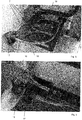
- Figure 1 shows the inventive end of line pick and place unit 1 which is located downstream from a packaging machine and which receives packages here from four lanes, i.e. each row of packages comprises four packages.
- the end of line pick and place unit 1 comprises an infeed conveyor, here an endless belt which transports the package towards a gripper unit 6, which comprises a multitude of grippers 7, here twelve grippers, which can pick up six packages from two lanes; i.e. two grippers are allocated to one package.
- the gripper unit is lowered until the grippers touch the packages. Then, a vacuum is applied between the packages and the grippers 7.
- the gripper unit is lifted and simultaneous and/or subsequently the gripper unit moves towards the outfeed conveyor 4 as depicted by the arrow.
- the infeed conveyor preferably stands still.
- the packages are lowered again, until they stand on the outfeed conveyor.
- the outfeed conveyor is in the present case provided as an endless belt.
- the inventive end of line pick and place unit 1 comprises a pusher 5, which is however not demanding. The pusher pushes packages which have been placed on an area before the pusher and beside the outfeed conveyor on the outfeed conveyor after the area of the outfeed conveyor in front of the pusher has been emptied by advancing the outfeed conveyor.
- a pitching conveyor 21 Downstream from the outfeed conveyor, there may be a pitching conveyor 21, which can be for example, the interface between the end of line pick and place unit 1 and a subsequent carton packaging machine.
- the inventive end of line pick and place unit 1 reduces packages in n parallel lanes on the infeed conveyor 3, here four parallel lanes to less, preferably one lane on the outfeed conveyor 4.
- the end of line pick and place unit 1 and the packaging machine 2 can exchange information for example via a common control system. Particularly information to synchronize the packaging machine and the end of line pick and place unit 1. For example, information about the index and/or the availability of packages to transferred can be exchanged. The information exchanged can also comprise data about packages in a format which need to be sorted out, because, for example, they are not sufficiently filled and/or the quality of the product in the package is not sufficient and/or the package is not properly closed and/or has a gas-atmosphere in the package which is not according to the specification.
- the inventive end of line pick and place unit 1 gets data about the position of such a package, particularly where it is located on the infeed convey 3.
- the gripper(s) which is/are allocated to such a deficient package is/are then not activated, e.g. no vacuum is applied to this/these gripper(s), so that the package is not lifted together with the gripper unit, but stays on the infeed conveyor. As soon as the infeed conveyor further advances, this package drops from the infeed conveyor, for example in a waste bin.
- FIG. 2 shows the gripper unit 6. It can be seen that the entire gripper unit is provided at vertical lifting means, here a frame 8 and a guiding means 9, here a guiding rod. For lowering and lifting the gripper unit, here the frame 8 is lowered and lifted by motor means and guided by the guiding means during this movement.
- the gripper unit is also connected to horizontal guiding means, here two guiding rods 10, along which the gripper unit can reciprocate to transport packages from the infeed- to the outfeed conveyor.
- the vertical movement and/or the horizontal movement are preferably driven by a motor 11 and a toothed belt.
- the motor is preferably a motor that provides a signal about the rotational position of its shaft, so that the horizontal and/or vertical position of the gripper unit can be derived.
- the grippers of the inventive end of line pick and place unit 1 do not move relative to the gripper unit 6 in which they are provided, but only move together with the housing 20 of the gripper unit.
- Figures 4 - 6 show details of the gripper unit 6, which comprises a housing 20, and a tool 12, which is in the present case provided as a plate.
- a multitude of grippers 7 is provided in a certain configuration, which is preferably tailormade for a specific application, i.e. adapted to the package(s) to be lifted.
- the tool may comprise a handle 15 and/or one or more, here three, recess(es) to reduce the weight of the tool and/or to simplify the inspection/maintenance of the tool.
- the housing preferably comprises guiding means 14, here U-shapes slots which guide the tool during installation and removal of the tool. It its operating position, the tool can be fixed by fixing means 13, which are released for removal of the tool from the housing.
- the inventive gripper unit may comprise a valve, particularly a valve-block 16 to provide the grippers individually and/or group-wise with energy, for example vacuum.
- a central connector 17 is provided at the tool.
- This connector can be connected to a vacuum-source and downstream from the connector 17, tubes 18 are provided, which connect the connector 17 with the individual grippers 7.
- three grippers 7 are tube-wise combined to one group to lift one package and three packages can be lifted simultaneously.
- FIG. 6 shows the plug 19 that is connected to the central connector 17. It can be seen that the plug comprises a multitude of sockets, which can be connected to corresponding recesses in the central connector 17. Hence, if needed each gripper 7 at the tool 12 can be supplied with vacuum individually. The plug is connected to the valve block, which shuts the vacuum for the individual gripper or an individual group of grippers on and off.
Applications Claiming Priority (2)
| Application Number | Priority Date | Filing Date | Title |
|---|---|---|---|
| EP17169116 | 2017-05-02 | ||
| EP17169360 | 2017-05-04 |
Publications (1)
| Publication Number | Publication Date |
|---|---|
| EP3453653A1 true EP3453653A1 (de) | 2019-03-13 |
Family
ID=62062913
Family Applications (1)
| Application Number | Title | Priority Date | Filing Date |
|---|---|---|---|
| EP18169004.1A Pending EP3453653A1 (de) | 2017-05-02 | 2018-04-24 | Linienendengreif- und -platzierungseinheit |
Country Status (1)
| Country | Link |
|---|---|
| EP (1) | EP3453653A1 (de) |
Cited By (1)
| Publication number | Priority date | Publication date | Assignee | Title |
|---|---|---|---|---|
| CN117383226A (zh) * | 2023-12-12 | 2024-01-12 | 常州市钧达轴承有限公司 | 一种轴承用上下料输送系统及其工作方法 |
Citations (5)
| Publication number | Priority date | Publication date | Assignee | Title |
|---|---|---|---|---|
| JPS60144237A (ja) * | 1983-12-27 | 1985-07-30 | Toyo Glass Kk | ガラスびんの移送装置 |
| DE4445108A1 (de) * | 1994-12-19 | 1996-06-20 | Ltg Lufttechnische Gmbh | Umsetzvorrichtung für Güter, insbesondere Dosen |
| GB2297955A (en) * | 1995-02-14 | 1996-08-21 | Gd Spa | Product conveyor line |
| EP1270462A1 (de) * | 2001-06-08 | 2003-01-02 | INDAG Gesellschaft für Industriebedarf mbH & Co. Betriebs KG | Übergabevorrichtung und -verfahren für Folienbeutel |
| EP2341001A1 (de) * | 2009-12-22 | 2011-07-06 | Automatisation et renovation du conditionnement dans les industries laitieres Arcil | Verfahren und Maschine zur Umverpackung von Artikeln zur Bildung von Artikellosen, bestehend aus einer Vielzahl von Artikeln und einer Umverpackung aus Karton |
-
2018
- 2018-04-24 EP EP18169004.1A patent/EP3453653A1/de active Pending
Patent Citations (5)
| Publication number | Priority date | Publication date | Assignee | Title |
|---|---|---|---|---|
| JPS60144237A (ja) * | 1983-12-27 | 1985-07-30 | Toyo Glass Kk | ガラスびんの移送装置 |
| DE4445108A1 (de) * | 1994-12-19 | 1996-06-20 | Ltg Lufttechnische Gmbh | Umsetzvorrichtung für Güter, insbesondere Dosen |
| GB2297955A (en) * | 1995-02-14 | 1996-08-21 | Gd Spa | Product conveyor line |
| EP1270462A1 (de) * | 2001-06-08 | 2003-01-02 | INDAG Gesellschaft für Industriebedarf mbH & Co. Betriebs KG | Übergabevorrichtung und -verfahren für Folienbeutel |
| EP2341001A1 (de) * | 2009-12-22 | 2011-07-06 | Automatisation et renovation du conditionnement dans les industries laitieres Arcil | Verfahren und Maschine zur Umverpackung von Artikeln zur Bildung von Artikellosen, bestehend aus einer Vielzahl von Artikeln und einer Umverpackung aus Karton |
Cited By (2)
| Publication number | Priority date | Publication date | Assignee | Title |
|---|---|---|---|---|
| CN117383226A (zh) * | 2023-12-12 | 2024-01-12 | 常州市钧达轴承有限公司 | 一种轴承用上下料输送系统及其工作方法 |
| CN117383226B (zh) * | 2023-12-12 | 2024-03-08 | 常州市钧达轴承有限公司 | 一种轴承用上下料输送系统及其工作方法 |
Similar Documents
| Publication | Publication Date | Title |
|---|---|---|
| CN106660648B (zh) | 运输设备 | |
| US4722653A (en) | Material handling for automated assembly facility | |
| CN108698771B (zh) | 具有多个出口的传送系统 | |
| RU2334668C2 (ru) | Устройство и способ изготовления упаковок для сосудов | |
| CN104443521A (zh) | 一种盒子自动装箱方法及其装箱设备 | |
| CN1048463C (zh) | 从运送箱内提取容器的装置 | |
| US11713147B2 (en) | Article picking and treating apparatus | |
| US6948608B2 (en) | Method and a device for transferring blister packs and the like to the feeding line of a packaging machine | |
| US11530060B2 (en) | Handling apparatus and/or packaging apparatus and method used to package article groups in outer packaging | |
| EP3453653A1 (de) | Linienendengreif- und -platzierungseinheit | |
| CN114450227A (zh) | 包装设备 | |
| US20230331417A1 (en) | Packaging machine with a grouping device and method for producing single-layer groups of partially overlapping products | |
| EP3626677A1 (de) | Verschluss- und verschlusssortiervorrichtung und -verfahren | |
| WO2021084451A1 (en) | Pick and place device for an apparatus for filling and closing articles, apparatus and method for filling and closing randomly fed articles | |
| JP2901933B2 (ja) | 箱詰装置 | |
| JP2003300504A (ja) | 物品の箱詰装置 | |
| BE1028934B1 (nl) | Producthanteringsapparaten, -systemen en geassocieerde werkwijzen | |
| CN110920966B (zh) | 用于包装物品的搬运设备和/或包装设备和方法 | |
| CS196510B1 (cs) | Zařízení pro ukládání a přívod obrobků | |
| CN108946183B (zh) | 高效盒体码垛机 | |
| CN210001152U (zh) | 一种自动补料组件 | |
| US20240092587A1 (en) | An article picking and placing system | |
| CN115922286A (zh) | 一种电机转子自动装配和检测生产线及其生产方法 | |
| CN117622596A (zh) | 一种烤花光瓶白酒高速包装生产线及包装装箱方法 | |
| CN115571425A (zh) | 连续式上开盖高速装盒机 |
Legal Events
| Date | Code | Title | Description |
|---|---|---|---|
| PUAI | Public reference made under article 153(3) epc to a published international application that has entered the european phase |
Free format text: ORIGINAL CODE: 0009012 |
|
| STAA | Information on the status of an ep patent application or granted ep patent |
Free format text: STATUS: THE APPLICATION HAS BEEN PUBLISHED |
|
| AK | Designated contracting states |
Kind code of ref document: A1 Designated state(s): AL AT BE BG CH CY CZ DE DK EE ES FI FR GB GR HR HU IE IS IT LI LT LU LV MC MK MT NL NO PL PT RO RS SE SI SK SM TR |
|
| AX | Request for extension of the european patent |
Extension state: BA ME |
|
| STAA | Information on the status of an ep patent application or granted ep patent |
Free format text: STATUS: REQUEST FOR EXAMINATION WAS MADE |
|
| 17P | Request for examination filed |
Effective date: 20190912 |
|
| RBV | Designated contracting states (corrected) |
Designated state(s): AL AT BE BG CH CY CZ DE DK EE ES FI FR GB GR HR HU IE IS IT LI LT LU LV MC MK MT NL NO PL PT RO RS SE SI SK SM TR |
|
| STAA | Information on the status of an ep patent application or granted ep patent |
Free format text: STATUS: EXAMINATION IS IN PROGRESS |
|
| 17Q | First examination report despatched |
Effective date: 20220105 |