EP3452631B1 - Method to operate an apparatus for feeding liquid metal to an evaporator device - Google Patents
Method to operate an apparatus for feeding liquid metal to an evaporator device Download PDFInfo
- Publication number
- EP3452631B1 EP3452631B1 EP17721357.6A EP17721357A EP3452631B1 EP 3452631 B1 EP3452631 B1 EP 3452631B1 EP 17721357 A EP17721357 A EP 17721357A EP 3452631 B1 EP3452631 B1 EP 3452631B1
- Authority
- EP
- European Patent Office
- Prior art keywords
- electromagnetic pump
- liquid metal
- pressure
- feed tube
- evaporator device
- Prior art date
- Legal status (The legal status is an assumption and is not a legal conclusion. Google has not performed a legal analysis and makes no representation as to the accuracy of the status listed.)
- Active
Links
- 229910001338 liquidmetal Inorganic materials 0.000 title claims description 85
- 238000000034 method Methods 0.000 title claims description 38
- OKTJSMMVPCPJKN-UHFFFAOYSA-N Carbon Chemical compound [C] OKTJSMMVPCPJKN-UHFFFAOYSA-N 0.000 claims description 12
- 229910002804 graphite Inorganic materials 0.000 claims description 12
- 239000010439 graphite Substances 0.000 claims description 12
- 230000005291 magnetic effect Effects 0.000 claims description 10
- 239000007789 gas Substances 0.000 description 44
- 230000008020 evaporation Effects 0.000 description 12
- 238000001704 evaporation Methods 0.000 description 12
- 239000007788 liquid Substances 0.000 description 12
- 238000005240 physical vapour deposition Methods 0.000 description 8
- 239000000463 material Substances 0.000 description 7
- 238000000576 coating method Methods 0.000 description 5
- 239000000203 mixture Substances 0.000 description 5
- 239000011248 coating agent Substances 0.000 description 4
- 238000010438 heat treatment Methods 0.000 description 4
- 238000011109 contamination Methods 0.000 description 3
- 230000035699 permeability Effects 0.000 description 3
- IJGRMHOSHXDMSA-UHFFFAOYSA-N Atomic nitrogen Chemical compound N#N IJGRMHOSHXDMSA-UHFFFAOYSA-N 0.000 description 2
- 238000000151 deposition Methods 0.000 description 2
- 239000011261 inert gas Substances 0.000 description 2
- 239000011344 liquid material Substances 0.000 description 2
- 230000008018 melting Effects 0.000 description 2
- 238000002844 melting Methods 0.000 description 2
- 229910052751 metal Inorganic materials 0.000 description 2
- 239000002184 metal Substances 0.000 description 2
- 230000001010 compromised effect Effects 0.000 description 1
- 239000000470 constituent Substances 0.000 description 1
- 238000010276 construction Methods 0.000 description 1
- 230000003247 decreasing effect Effects 0.000 description 1
- 238000007872 degassing Methods 0.000 description 1
- 230000008021 deposition Effects 0.000 description 1
- 230000000694 effects Effects 0.000 description 1
- 238000002474 experimental method Methods 0.000 description 1
- 239000003302 ferromagnetic material Substances 0.000 description 1
- 230000008014 freezing Effects 0.000 description 1
- 238000007710 freezing Methods 0.000 description 1
- 230000006698 induction Effects 0.000 description 1
- 239000000155 melt Substances 0.000 description 1
- 229910052757 nitrogen Inorganic materials 0.000 description 1
- 230000003647 oxidation Effects 0.000 description 1
- 238000007254 oxidation reaction Methods 0.000 description 1
- 239000011343 solid material Substances 0.000 description 1
- 239000000758 substrate Substances 0.000 description 1
- 238000002207 thermal evaporation Methods 0.000 description 1
- 238000001771 vacuum deposition Methods 0.000 description 1
- 238000005303 weighing Methods 0.000 description 1
- 229910052725 zinc Inorganic materials 0.000 description 1
Images
Classifications
-
- C—CHEMISTRY; METALLURGY
- C23—COATING METALLIC MATERIAL; COATING MATERIAL WITH METALLIC MATERIAL; CHEMICAL SURFACE TREATMENT; DIFFUSION TREATMENT OF METALLIC MATERIAL; COATING BY VACUUM EVAPORATION, BY SPUTTERING, BY ION IMPLANTATION OR BY CHEMICAL VAPOUR DEPOSITION, IN GENERAL; INHIBITING CORROSION OF METALLIC MATERIAL OR INCRUSTATION IN GENERAL
- C23C—COATING METALLIC MATERIAL; COATING MATERIAL WITH METALLIC MATERIAL; SURFACE TREATMENT OF METALLIC MATERIAL BY DIFFUSION INTO THE SURFACE, BY CHEMICAL CONVERSION OR SUBSTITUTION; COATING BY VACUUM EVAPORATION, BY SPUTTERING, BY ION IMPLANTATION OR BY CHEMICAL VAPOUR DEPOSITION, IN GENERAL
- C23C14/00—Coating by vacuum evaporation, by sputtering or by ion implantation of the coating forming material
- C23C14/06—Coating by vacuum evaporation, by sputtering or by ion implantation of the coating forming material characterised by the coating material
- C23C14/14—Metallic material, boron or silicon
- C23C14/16—Metallic material, boron or silicon on metallic substrates or on substrates of boron or silicon
-
- C—CHEMISTRY; METALLURGY
- C23—COATING METALLIC MATERIAL; COATING MATERIAL WITH METALLIC MATERIAL; CHEMICAL SURFACE TREATMENT; DIFFUSION TREATMENT OF METALLIC MATERIAL; COATING BY VACUUM EVAPORATION, BY SPUTTERING, BY ION IMPLANTATION OR BY CHEMICAL VAPOUR DEPOSITION, IN GENERAL; INHIBITING CORROSION OF METALLIC MATERIAL OR INCRUSTATION IN GENERAL
- C23C—COATING METALLIC MATERIAL; COATING MATERIAL WITH METALLIC MATERIAL; SURFACE TREATMENT OF METALLIC MATERIAL BY DIFFUSION INTO THE SURFACE, BY CHEMICAL CONVERSION OR SUBSTITUTION; COATING BY VACUUM EVAPORATION, BY SPUTTERING, BY ION IMPLANTATION OR BY CHEMICAL VAPOUR DEPOSITION, IN GENERAL
- C23C14/00—Coating by vacuum evaporation, by sputtering or by ion implantation of the coating forming material
- C23C14/22—Coating by vacuum evaporation, by sputtering or by ion implantation of the coating forming material characterised by the process of coating
- C23C14/24—Vacuum evaporation
- C23C14/246—Replenishment of source material
-
- C—CHEMISTRY; METALLURGY
- C23—COATING METALLIC MATERIAL; COATING MATERIAL WITH METALLIC MATERIAL; CHEMICAL SURFACE TREATMENT; DIFFUSION TREATMENT OF METALLIC MATERIAL; COATING BY VACUUM EVAPORATION, BY SPUTTERING, BY ION IMPLANTATION OR BY CHEMICAL VAPOUR DEPOSITION, IN GENERAL; INHIBITING CORROSION OF METALLIC MATERIAL OR INCRUSTATION IN GENERAL
- C23C—COATING METALLIC MATERIAL; COATING MATERIAL WITH METALLIC MATERIAL; SURFACE TREATMENT OF METALLIC MATERIAL BY DIFFUSION INTO THE SURFACE, BY CHEMICAL CONVERSION OR SUBSTITUTION; COATING BY VACUUM EVAPORATION, BY SPUTTERING, BY ION IMPLANTATION OR BY CHEMICAL VAPOUR DEPOSITION, IN GENERAL
- C23C14/00—Coating by vacuum evaporation, by sputtering or by ion implantation of the coating forming material
- C23C14/06—Coating by vacuum evaporation, by sputtering or by ion implantation of the coating forming material characterised by the coating material
- C23C14/14—Metallic material, boron or silicon
-
- C—CHEMISTRY; METALLURGY
- C23—COATING METALLIC MATERIAL; COATING MATERIAL WITH METALLIC MATERIAL; CHEMICAL SURFACE TREATMENT; DIFFUSION TREATMENT OF METALLIC MATERIAL; COATING BY VACUUM EVAPORATION, BY SPUTTERING, BY ION IMPLANTATION OR BY CHEMICAL VAPOUR DEPOSITION, IN GENERAL; INHIBITING CORROSION OF METALLIC MATERIAL OR INCRUSTATION IN GENERAL
- C23C—COATING METALLIC MATERIAL; COATING MATERIAL WITH METALLIC MATERIAL; SURFACE TREATMENT OF METALLIC MATERIAL BY DIFFUSION INTO THE SURFACE, BY CHEMICAL CONVERSION OR SUBSTITUTION; COATING BY VACUUM EVAPORATION, BY SPUTTERING, BY ION IMPLANTATION OR BY CHEMICAL VAPOUR DEPOSITION, IN GENERAL
- C23C14/00—Coating by vacuum evaporation, by sputtering or by ion implantation of the coating forming material
- C23C14/22—Coating by vacuum evaporation, by sputtering or by ion implantation of the coating forming material characterised by the process of coating
- C23C14/56—Apparatus specially adapted for continuous coating; Arrangements for maintaining the vacuum, e.g. vacuum locks
-
- H—ELECTRICITY
- H02—GENERATION; CONVERSION OR DISTRIBUTION OF ELECTRIC POWER
- H02K—DYNAMO-ELECTRIC MACHINES
- H02K44/00—Machines in which the dynamo-electric interaction between a plasma or flow of conductive liquid or of fluid-borne conductive or magnetic particles and a coil system or magnetic field converts energy of mass flow into electrical energy or vice versa
- H02K44/02—Electrodynamic pumps
- H02K44/04—Conduction pumps
Definitions
- the invention relates to a method to operate an apparatus for feeding liquid metal to an evaporator device in a vacuum chamber.
- a device is for instance used in depositing of a metal coating on a substrate by means of physical vapour deposition (PVD).
- PVD physical vapour deposition
- the PVD coating device disclosed in US2664852 has a reservoir for liquid metal in the vacuum chamber. With this set-up the maximum campaign length is quite limited. In more recent PVD coating devices the liquid metal reservoir is places outside the vacuum chamber, see for instance WO2012081738 . However, due to the pressure difference between the vacuum at the evaporator device and the liquid metal reservoir a force is executed on the liquid metal in the reservoir which needs to be controlled. This force will change when the liquid level in the reservoir drops, the vacuum pressure at the evaporator device changes or the level in the evaporator device changes and needs to be controlled to keep a constant supply to the evaporator device to ensure a constant evaporation.
- the supply of liquid metal from the liquid metal container to the evaporator device can be controlled in different ways.
- US3059612 it is disclosed to lift the container with liquid metal in order to keep the height difference between the liquid metal surface in the evaporator device and the level in the liquid metal container constant.
- a change in barometric pressure will already give rise to a different level in the evaporator device and as a result a change in evaporation.
- Patent documents US 4392786 and CN 204805055 U disclose electromagnetic pumps for liquid metal.
- one or more of the objectives of the invention are realized by providing a method to operate an apparatus for feeding liquid metal to an evaporator device in a vacuum chamber, wherein the feed tube runs from a container adapted to contain a liquid metal to the evaporator device and wherein an electromagnetic pump is provided in the feed tube and a valve in the feed tube between the electromagnetic pump and the evaporator device, characterised in that the method comprises:
- the method according the invention has the advantage that by using a gas permeable electromagnetic pump the feed tube can be filled with liquid metal, while driving out the majority of air or gas present in the feed tube, before the valve is opened.
- the evaporator device can be emptied in a first step till the liquid metal is below the valve in the feed tube, after which the valve is closed and the feed tube can be emptied completely by having air or gas entering the feed tube through the gas permeable electromagnetic pump.
- a prerequisite for the use of a gas permeable electromagnetic pump as described is to have the gas permeable electromagnetic pump enclosed in a pressure controlled enclosure. Without such an enclosure air would be drawn into the feed tube through the gas permeable electromagnetic pump during normal operation and the vacuum of the vacuum chamber would still be compromised.
- the pressure in the pressure controlled enclosure varies in a pressure range from 1 - 1000 mbar or about atmospheric pressure. With the filling of the feed tube and during normal operation the pressure in the pressure controlled enclosure is preferably kept in the range of 1 - 200 mbar. With the pressure in this range in the pressure controlled enclosure no air or other gas will be drawn via the feed system into the vacuum chamber.
- the pressure in the pressure controlled enclosure is increased to atmospheric pressure or higher in order to let air or other gas enter the feed tube through the gas permeable electromagnetic pump.
- the pressure in the pressure controlled enclosure is increased after the level of the liquid metal is below the valve in the feed tube. Below the valve in the feed tube is directly below the valve or at a level in the electromagnetic pump, which might be the level at which the electromagnetic pump can still exert a Lorentz force on the liquid metal.
- the pressure controlled enclosure also encloses at least part of the feed tube.
- This feature provides the advantage of a reduced heat loss because heat losses through convection are reduced to a great extent in a vacuum.
- Another advantage is that by providing that the enclosed part of the feed tube that is located above the electromagnetic pump is at least partially gas permeable, the feed tube can be used in removing air or other gas from the feed tube with the filling of the feed tube and letting air into the feed tube with the draining of the feed tube. This applies specially for the part of the feed tube between the gas permeable electromagnetic pump and the valve in the feed tube.
- the electromagnetic pump is at least partially made of graphite. It was found that graphite has a certain permeability for gasses like for instance N2 and air. For liquid metal, such as Zn or Mg or a mixture of liquid metals the graphite pump is impermeable. The gas permeability of graphite is controlled by controlling the pressure in the pressure controlled enclosure as described above.
- the enclosed part of the feed tube is at least partially made of graphite. This has the same effect as described for the gas permeable electromagnetic pump.
- the container adapted to contain a liquid metal is a closed container and wherein the force exerted on the liquid metal is controlled by controlling the pressure of the gas in the closed container.
- the force to be exerted on the liquid metal in the container can be controlled very easily and can be varied rapidly if need be.
- closed container will mean a container wherein the pressure and/or the composition of the gas inside the container is or can be controlled.
- the method includes that a return tube is provided, which runs from the evaporator device to the container, an electromagnetic pump, which is at least partially gas permeable, in the return tube and a valve in the return tube between the electromagnetic pump and the vacuum chamber is provided, wherein the electromagnetic pump in the return tube is provided in the pressure controlled enclosure, comprising the step of increasing the pressure and/or maintaining an increased pressure in the pressure controlled enclosure before and/or when draining liquid metal from the electromagnetic pump.
- Control of the composition means that the composition remains constant as much as possible and is not changed because of different evaporation rates of constituents.
- the disclosure also includes an electromagnetic pump for use in the method wherein the electromagnetic pump is at least partially made of a gas permeable material.
- the gas permeable material is graphite.
- the invention provides an apparatus for feeding liquid metal to an evaporator device in a vacuum chamber, the apparatus further comprising a container adapted to contain a liquid metal, a feed tube from the container to the evaporator device and an electromagnetic pump provided in the feed tube, wherein the electromagnetic pump is at least partially a gas permeable electromagnetic pump and wherein a pressure controlled enclosure is provided which encloses the electromagnetic pump.
- the pressure controlled enclosure encloses at least part of the feed tube.
- the gas permeable electromagnetic pump is at least partially made of graphite.
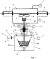
- Fig.1 shows a schematic view of an apparatus with a vacuum chamber 1, on both sides provided with vacuum locks 2,3, through which a strip 4 is guided.
- An evaporator device 5 is positioned inside the vacuum chamber 1 and connected to a vapour distributor 6.
- the means to supply sufficient energy to the evaporator device, such as in induction coil, are also placed inside the vacuum chamber. For the sake of clarity these means are not shown in the drawing.
- the vacuum chamber is further provided with vacuum pump 7 and manometer 8.
- a closed container 9 is provided with inside the container a vessel 10 to hold a liquid metal.
- the closed container 9 is further provided with a pump 11, manometer 12 and overpressure relay 13.
- the vessel is provided with heating means (not shown) to heat and melt the metal and/or to keep the liquid metal at a certain temperature.
- a gas supply 31 with a valve 32 is connected to closed container 9 to replace the air initially present in container 9 with a non-oxidising gas, for instance Nitrogen.
- Lifting means 14 are provided to lift and lower vessel 10 to be able to immerse the end of feed tube 15 into the liquid metal or lift it out of the liquid metal.
- the lifting means 14 can also be used in the control of the flow rate of the liquid metal to the evaporator device 5, since with the lifting and lowering the distance between the liquid level in the vessel and that in the evaporation device changes.
- the vessel 10 is placed on weighing devices 35 which allows to continuously weigh the content of vessel 10 which provides extra information on the flow rate of the liquid metal and the evaporation rate.
- the pump 11 is used to lower the pressure in the closed container.
- the air in the closed container can be removed and replaced completely or partially with an inert gas. With this operation the air is first partially removed therewith lowering the pressure before being replaced by an inert gas after which the pressure in the closed container is adjusted and controlled in order to control the flow rate of the liquid metal to the evaporator device.
- the feed tube 15 runs from the vessel 10 inside the closed container 9 in upward direction to the evaporator device 5 and in the feed tube a gas permeable electromagnetic pump 16 and a valve 17 are provided.
- the gas permeable electromagnetic pump 16 and valve 17 are placed inside a pressure controlled enclosure 18.
- the pressure controlled enclosure 18 is kept at a low vacuum during operation which prevent heat losses through convection from the electromagnetic pump 16 as well as from the feed tube 15 to a great degree.
- the vacuum enclosure 18 is provided with a vacuum pump 34 and a manometer 35.
- valve 17 is closed. It is important that all components are thoroughly heated before the filling procedure commences.
- the pressure inside the pressure controlled enclosure 18 is lowered or already lowered to a pressure in the range of 1 - 200 mbar. Because of the permeability of the gas permeable electromagnetic pump the air or gas present in the feed tube 15 is driven out of through the gas permeable electromagnetic pump. This process can be speeded up or assisted by increasing the pressure inside the closed container 9 to forced the liquid metal into feed tube 15. With also the feed tube being gas permeable up to at least valve 17 all or as good as all of the air or gas in the feed tube 15 can be driven out before valve 17 is opened. In this way it is prevented that the vacuum pressure in the vacuum chamber is affected.
- the part of feed tube 15 below the pressure controlled enclosure 18, that is the part of the feed tube in bellow 19 and inside closed container 9, should be gas impermeable.
- the liquid metal is drawn from the evaporator device 5 and returned to vessel 10 in container 9.
- the gas permeable electromagnetic pump 16 is controlled to force the liquid metal to vessel 10.
- valve 17 is closed and the vacuum chamber is no longer in connection with the system below valve 17.
- the pressure inside the pressure controlled enclosure 18 is raised and with the increased pressure the air or gas in the pressure controlled enclosure will easily be drawn into the feed tube through the gas permeable electromagnetic pump and the gas permeable feed tube as far as provided.
- This process can be speeded up or assisted by decreasing the pressure inside the closed container 9 to force the liquid metal into the liquid container. However care should be taken that no evaporation will occur and as such contamination of the closed container.
- the pressure controlled enclosure 18 connects to the closed container 9 and the vacuum chamber 1 by means of bellows 19, 20.
- the connection by means of the bellows 19, 20 is to the outside of the closed container 9 and the vacuum chamber 1 and does not connect the internal spaces of container 9 and vacuum chamber 1.
- the unavoidable vacuum leak at the feed through of the feed tube 15 into the vacuum chamber 1 is much less because of the low vacuum in the pressure controlled enclosure 18.
- the electromagnetic pump 16 pump is provided with a permanent magnet 21 to generate a magnetic field and a power supply to pass a current through the liquid metal in the electromagnetic pump.
- the Lorentz force resulting from the magnetic field and the current will exert a force on the liquid metal which is used in the control of the flow rate of the liquid metal.
- the Lorentz force only works as long as the liquid metal is in contact with the electrodes 22 of the electromagnetic pump and within the magnetic field of permanent magnet 21. As a result when the liquid metal is forced downwards the liquid metal level can not be lower than a level at about the height of the electrodes.
- the magnet 21 is not overheated because this will result in a decrease of the strength of the magnetic field. For that reason the magnet 21 is placed outside the pressure controlled enclosure 18, which at least at the location of the magnet and its magnetic field is made of a non-ferromagnetic material.
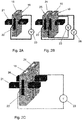
- Fig.2A shows a schematic view of an electromagnetic pump 16 for a feed tube 15 with the electrodes 22 on opposite sides against the body of the electromagnetic pump 16.
- the electrodes 22 are connected to a power supply 23, in this case a variable DC power supply.
- the electrodes are not in direct contact with the liquid metal which has the advantage that the electrodes will last far longer than electrodes that are in direct contact with the liquid metal.
- the material of the gas permeable electromagnetic pump is electrically conductive, which is the case with an electromagnetic pump of graphite.
- An additional advantage is that the current passes through the body of the electromagnetic pump as a result of which the electromagnetic pump can be heated through resistance heating. The method as described works of course also with gas permeable electromagnetic pumps wherein the electrodes are in direct contact with the liquid metal.
- Perpendicular to the electrodes 22 are the poles of magnet 21, which in this configuration are two permanent magnets connected by means of a yoke (not shown).
- a yoke not shown
- an electromagnet for instance an electromagnet with a DC coil. By varying the current through the coil the magnetic field could be varied.
- variable DC power supply and a DC coil instead of a variable DC power supply and a DC coil it is as well possible to use a variable AC power supply and an AC coil for the electromagnet.
- Fig.2B shows a configuration with a feed tube 15 and a return tube 24 next to each other with electromagnetic pumps 18, 25 for respectively the feed tube 15 and return tube 24.
- the magnetic field for both the feed tube 15 and the return tube 24 is provided with the same permanent magnets 21.
- Separate variable DC power supplies 23, 26 are provided for respectively the feed tube 15 and the return tube 24 which are reversely connected to the electrodes since the Lorentz forces should be in opposite direction.
- the feed tube 15 and the return tube 24 are in thermal contact with each other but electrically isolated from each other.
- the flow rate in the return tube will differ by the evaporation rate from the flow rate in the feed tube and for that reason the current through the return tube 24 will be larger than through the feed tube 15.
- Fig.2C shows a configuration wherein the electrodes 22 of feed tube 15 and feed tube 25 are connected in series which only requires one power supply 23 and wherein the same current passes through both feed tubes.
- the magnetic field of the magnet 21, 36 in each tube 15, 24 is controlled separately.
- the filling of the feed tube 15 is the same as for the configuration with only a feed tube.
- the return tube 24 is filled in the same manner as the feed tube in order to prevent that air or gas in the return tube up to a valve in the return tube, which valve is provided between the gas permeable electromagnetic pump 25 and the evaporator device 5, is drawn into the vacuum chamber when opening the valve in the return tube.
- the draining of the return tube 24 is done in the same manner as the draining of the feed tube 15 as described for the configuration with only a feed tube.
Landscapes
- Chemical & Material Sciences (AREA)
- Engineering & Computer Science (AREA)
- Chemical Kinetics & Catalysis (AREA)
- Materials Engineering (AREA)
- Mechanical Engineering (AREA)
- Metallurgy (AREA)
- Organic Chemistry (AREA)
- Power Engineering (AREA)
- Vaporization, Distillation, Condensation, Sublimation, And Cold Traps (AREA)
- Physical Vapour Deposition (AREA)
- Filling Or Discharging Of Gas Storage Vessels (AREA)
Applications Claiming Priority (2)
| Application Number | Priority Date | Filing Date | Title |
|---|---|---|---|
| EP16168162 | 2016-05-03 | ||
| PCT/EP2017/060317 WO2017191083A1 (en) | 2016-05-03 | 2017-05-01 | Method to operate an apparatus for feeding liquid metal to an evaporator device |
Publications (2)
| Publication Number | Publication Date |
|---|---|
| EP3452631A1 EP3452631A1 (en) | 2019-03-13 |
| EP3452631B1 true EP3452631B1 (en) | 2020-03-25 |
Family
ID=56083901
Family Applications (1)
| Application Number | Title | Priority Date | Filing Date |
|---|---|---|---|
| EP17721357.6A Active EP3452631B1 (en) | 2016-05-03 | 2017-05-01 | Method to operate an apparatus for feeding liquid metal to an evaporator device |
Country Status (8)
| Country | Link |
|---|---|
| US (1) | US11414744B2 (enExample) |
| EP (1) | EP3452631B1 (enExample) |
| JP (1) | JP7182466B2 (enExample) |
| KR (1) | KR102360308B1 (enExample) |
| CN (1) | CN109072410B (enExample) |
| AU (1) | AU2017260148B2 (enExample) |
| ES (1) | ES2786975T3 (enExample) |
| WO (1) | WO2017191083A1 (enExample) |
Families Citing this family (6)
| Publication number | Priority date | Publication date | Assignee | Title |
|---|---|---|---|---|
| WO2017191081A1 (en) | 2016-05-03 | 2017-11-09 | Tata Steel Nederland Technology B.V. | Method to control the temperature of an electromagnetic pump |
| EP3452633B1 (en) | 2016-05-03 | 2020-03-25 | Tata Steel Nederland Technology B.V. | Apparatus for feeding a liquid metal to an evaporator device |
| CN107761058B (zh) * | 2017-11-14 | 2018-11-13 | 中国科学院光电研究院 | 多元合金薄膜的制备装置及其制备方法 |
| CN113930738B (zh) * | 2020-06-29 | 2023-09-12 | 宝山钢铁股份有限公司 | 一种真空镀膜用的金属蒸汽调制装置及其调制方法 |
| CN115094385A (zh) * | 2022-07-21 | 2022-09-23 | 浙江艾微普科技有限公司 | 一种含有液体供给系统的镀膜设备和镀膜方法 |
| CN118756099B (zh) * | 2024-09-09 | 2024-12-17 | 湘潭宏大真空技术股份有限公司 | 一种用于af膜的蒸发镀膜装置 |
Family Cites Families (20)
| Publication number | Priority date | Publication date | Assignee | Title |
|---|---|---|---|---|
| US2664852A (en) | 1950-04-27 | 1954-01-05 | Nat Res Corp | Vapor coating apparatus |
| US3059612A (en) | 1959-10-19 | 1962-10-23 | Wean Engineering Co Inc | Vacuum coating apparatus |
| US3408224A (en) | 1964-06-25 | 1968-10-29 | Pennsalt Chemicals Corp | Vapor coating employing degassing of coating metal |
| US3581766A (en) | 1968-08-02 | 1971-06-01 | Jones & Laughlin Steel Corp | Supplying liquid to a vacuum chamber |
| US3550924A (en) | 1968-12-06 | 1970-12-29 | United States Steel Corp | Mechanism for controlling flow of liquid to a vacuum-treating vessel |
| JPS5938379B2 (ja) | 1979-09-14 | 1984-09-17 | 松下電工株式会社 | 屋根材 |
| US4392786A (en) * | 1980-10-16 | 1983-07-12 | Merenkov Jury F | Electromagnetic induction pump |
| JPS5938379A (ja) | 1982-08-26 | 1984-03-02 | Mitsubishi Heavy Ind Ltd | 真空蒸着装置のスタ−トアツプ法 |
| JP3452617B2 (ja) * | 1993-12-10 | 2003-09-29 | 真空冶金株式会社 | ガスデポジション装置 |
| US7339139B2 (en) | 2003-10-03 | 2008-03-04 | Darly Custom Technology, Inc. | Multi-layered radiant thermal evaporator and method of use |
| DE102004041855B4 (de) | 2004-04-27 | 2007-09-13 | Von Ardenne Anlagentechnik Gmbh | Vorrichtung und Verfahren zur kontinuierlichen thermischen Vakuumbeschichtung |
| JP5259452B2 (ja) * | 2008-06-19 | 2013-08-07 | 一般財団法人電力中央研究所 | 電磁ポンプ吐出量測定方法 |
| US20100124022A1 (en) | 2008-11-14 | 2010-05-20 | Suad Causevic | Thermoelectric cooling apparatus and method for cooling an integrated circuit |
| KR101639811B1 (ko) | 2009-09-28 | 2016-07-15 | 주식회사 포스코 | 용융금속 공급장치 |
| EP2652167B1 (en) | 2010-12-13 | 2015-04-08 | Posco | Continuous coating apparatus |
| ES2566607T3 (es) * | 2012-03-30 | 2016-04-14 | Tata Steel Nederland Technology B.V. | Método y aparato para cargar metal líquido en un dispositivo evaporador |
| WO2015067662A1 (en) * | 2013-11-05 | 2015-05-14 | Tata Steel Nederland Technology B.V. | Method and apparatus for controlling the composition of liquid metal in an evaporator device |
| CN204805055U (zh) * | 2015-04-29 | 2015-11-25 | 周小林 | 电磁泵 |
| WO2017191081A1 (en) | 2016-05-03 | 2017-11-09 | Tata Steel Nederland Technology B.V. | Method to control the temperature of an electromagnetic pump |
| EP3452633B1 (en) | 2016-05-03 | 2020-03-25 | Tata Steel Nederland Technology B.V. | Apparatus for feeding a liquid metal to an evaporator device |
-
2017
- 2017-05-01 AU AU2017260148A patent/AU2017260148B2/en not_active Ceased
- 2017-05-01 JP JP2018557815A patent/JP7182466B2/ja active Active
- 2017-05-01 EP EP17721357.6A patent/EP3452631B1/en active Active
- 2017-05-01 US US16/098,461 patent/US11414744B2/en active Active
- 2017-05-01 ES ES17721357T patent/ES2786975T3/es active Active
- 2017-05-01 WO PCT/EP2017/060317 patent/WO2017191083A1/en not_active Ceased
- 2017-05-01 KR KR1020187033592A patent/KR102360308B1/ko not_active Expired - Fee Related
- 2017-05-01 CN CN201780027325.0A patent/CN109072410B/zh active Active
Non-Patent Citations (1)
| Title |
|---|
| None * |
Also Published As
| Publication number | Publication date |
|---|---|
| CN109072410B (zh) | 2021-05-07 |
| CN109072410A (zh) | 2018-12-21 |
| AU2017260148A1 (en) | 2018-11-15 |
| WO2017191083A1 (en) | 2017-11-09 |
| EP3452631A1 (en) | 2019-03-13 |
| JP7182466B2 (ja) | 2022-12-02 |
| KR102360308B1 (ko) | 2022-02-08 |
| US11414744B2 (en) | 2022-08-16 |
| ES2786975T3 (es) | 2020-10-14 |
| JP2019515140A (ja) | 2019-06-06 |
| US20190264320A1 (en) | 2019-08-29 |
| AU2017260148B2 (en) | 2022-08-25 |
| KR20190003589A (ko) | 2019-01-09 |
Similar Documents
| Publication | Publication Date | Title |
|---|---|---|
| EP3452631B1 (en) | Method to operate an apparatus for feeding liquid metal to an evaporator device | |
| EP3452632B1 (en) | Method to control the temperature of an electromagnetic pump | |
| AU2017260147B2 (en) | Apparatus for feeding a liquid material to an evaporator device | |
| JP6313746B2 (ja) | 液体金属を蒸発器に供給する方法および装置 | |
| EP3849727B1 (en) | Casting equipment | |
| WO2005023459A1 (en) | Fluid feed system for a casting application | |
| SU822989A1 (ru) | Устройство перекачки металлов | |
| HU188885B (en) | Electromagnetic metal melt pump, for suction and feeding of metal melts from furnaces |
Legal Events
| Date | Code | Title | Description |
|---|---|---|---|
| STAA | Information on the status of an ep patent application or granted ep patent |
Free format text: STATUS: UNKNOWN |
|
| STAA | Information on the status of an ep patent application or granted ep patent |
Free format text: STATUS: THE INTERNATIONAL PUBLICATION HAS BEEN MADE |
|
| PUAI | Public reference made under article 153(3) epc to a published international application that has entered the european phase |
Free format text: ORIGINAL CODE: 0009012 |
|
| STAA | Information on the status of an ep patent application or granted ep patent |
Free format text: STATUS: REQUEST FOR EXAMINATION WAS MADE |
|
| 17P | Request for examination filed |
Effective date: 20181203 |
|
| AK | Designated contracting states |
Kind code of ref document: A1 Designated state(s): AL AT BE BG CH CY CZ DE DK EE ES FI FR GB GR HR HU IE IS IT LI LT LU LV MC MK MT NL NO PL PT RO RS SE SI SK SM TR |
|
| AX | Request for extension of the european patent |
Extension state: BA ME |
|
| DAV | Request for validation of the european patent (deleted) | ||
| DAX | Request for extension of the european patent (deleted) | ||
| REG | Reference to a national code |
Ref country code: DE Ref legal event code: R079 Ref document number: 602017013651 Country of ref document: DE Free format text: PREVIOUS MAIN CLASS: C23C0014160000 Ipc: H02K0044040000 |
|
| GRAP | Despatch of communication of intention to grant a patent |
Free format text: ORIGINAL CODE: EPIDOSNIGR1 |
|
| STAA | Information on the status of an ep patent application or granted ep patent |
Free format text: STATUS: GRANT OF PATENT IS INTENDED |
|
| RIC1 | Information provided on ipc code assigned before grant |
Ipc: C23C 14/16 20060101ALI20191001BHEP Ipc: H02K 44/04 20060101AFI20191001BHEP Ipc: H02K 44/02 20060101ALI20191001BHEP Ipc: C23C 14/24 20060101ALI20191001BHEP |
|
| INTG | Intention to grant announced |
Effective date: 20191016 |
|
| GRAS | Grant fee paid |
Free format text: ORIGINAL CODE: EPIDOSNIGR3 |
|
| GRAA | (expected) grant |
Free format text: ORIGINAL CODE: 0009210 |
|
| STAA | Information on the status of an ep patent application or granted ep patent |
Free format text: STATUS: THE PATENT HAS BEEN GRANTED |
|
| AK | Designated contracting states |
Kind code of ref document: B1 Designated state(s): AL AT BE BG CH CY CZ DE DK EE ES FI FR GB GR HR HU IE IS IT LI LT LU LV MC MK MT NL NO PL PT RO RS SE SI SK SM TR |
|
| REG | Reference to a national code |
Ref country code: GB Ref legal event code: FG4D |
|
| REG | Reference to a national code |
Ref country code: AT Ref legal event code: REF Ref document number: 1249719 Country of ref document: AT Kind code of ref document: T Effective date: 20200415 Ref country code: IE Ref legal event code: FG4D |
|
| REG | Reference to a national code |
Ref country code: DE Ref legal event code: R096 Ref document number: 602017013651 Country of ref document: DE |
|
| REG | Reference to a national code |
Ref country code: SE Ref legal event code: TRGR |
|
| PG25 | Lapsed in a contracting state [announced via postgrant information from national office to epo] |
Ref country code: RS Free format text: LAPSE BECAUSE OF FAILURE TO SUBMIT A TRANSLATION OF THE DESCRIPTION OR TO PAY THE FEE WITHIN THE PRESCRIBED TIME-LIMIT Effective date: 20200325 Ref country code: FI Free format text: LAPSE BECAUSE OF FAILURE TO SUBMIT A TRANSLATION OF THE DESCRIPTION OR TO PAY THE FEE WITHIN THE PRESCRIBED TIME-LIMIT Effective date: 20200325 Ref country code: NO Free format text: LAPSE BECAUSE OF FAILURE TO SUBMIT A TRANSLATION OF THE DESCRIPTION OR TO PAY THE FEE WITHIN THE PRESCRIBED TIME-LIMIT Effective date: 20200625 |
|
| PG25 | Lapsed in a contracting state [announced via postgrant information from national office to epo] |
Ref country code: LV Free format text: LAPSE BECAUSE OF FAILURE TO SUBMIT A TRANSLATION OF THE DESCRIPTION OR TO PAY THE FEE WITHIN THE PRESCRIBED TIME-LIMIT Effective date: 20200325 Ref country code: GR Free format text: LAPSE BECAUSE OF FAILURE TO SUBMIT A TRANSLATION OF THE DESCRIPTION OR TO PAY THE FEE WITHIN THE PRESCRIBED TIME-LIMIT Effective date: 20200626 Ref country code: BG Free format text: LAPSE BECAUSE OF FAILURE TO SUBMIT A TRANSLATION OF THE DESCRIPTION OR TO PAY THE FEE WITHIN THE PRESCRIBED TIME-LIMIT Effective date: 20200625 Ref country code: HR Free format text: LAPSE BECAUSE OF FAILURE TO SUBMIT A TRANSLATION OF THE DESCRIPTION OR TO PAY THE FEE WITHIN THE PRESCRIBED TIME-LIMIT Effective date: 20200325 |
|
| REG | Reference to a national code |
Ref country code: NL Ref legal event code: MP Effective date: 20200325 |
|
| REG | Reference to a national code |
Ref country code: LT Ref legal event code: MG4D |
|
| PG25 | Lapsed in a contracting state [announced via postgrant information from national office to epo] |
Ref country code: NL Free format text: LAPSE BECAUSE OF FAILURE TO SUBMIT A TRANSLATION OF THE DESCRIPTION OR TO PAY THE FEE WITHIN THE PRESCRIBED TIME-LIMIT Effective date: 20200325 |
|
| REG | Reference to a national code |
Ref country code: ES Ref legal event code: FG2A Ref document number: 2786975 Country of ref document: ES Kind code of ref document: T3 Effective date: 20201014 |
|
| PG25 | Lapsed in a contracting state [announced via postgrant information from national office to epo] |
Ref country code: SM Free format text: LAPSE BECAUSE OF FAILURE TO SUBMIT A TRANSLATION OF THE DESCRIPTION OR TO PAY THE FEE WITHIN THE PRESCRIBED TIME-LIMIT Effective date: 20200325 Ref country code: LT Free format text: LAPSE BECAUSE OF FAILURE TO SUBMIT A TRANSLATION OF THE DESCRIPTION OR TO PAY THE FEE WITHIN THE PRESCRIBED TIME-LIMIT Effective date: 20200325 Ref country code: PT Free format text: LAPSE BECAUSE OF FAILURE TO SUBMIT A TRANSLATION OF THE DESCRIPTION OR TO PAY THE FEE WITHIN THE PRESCRIBED TIME-LIMIT Effective date: 20200818 Ref country code: SK Free format text: LAPSE BECAUSE OF FAILURE TO SUBMIT A TRANSLATION OF THE DESCRIPTION OR TO PAY THE FEE WITHIN THE PRESCRIBED TIME-LIMIT Effective date: 20200325 Ref country code: IS Free format text: LAPSE BECAUSE OF FAILURE TO SUBMIT A TRANSLATION OF THE DESCRIPTION OR TO PAY THE FEE WITHIN THE PRESCRIBED TIME-LIMIT Effective date: 20200725 Ref country code: RO Free format text: LAPSE BECAUSE OF FAILURE TO SUBMIT A TRANSLATION OF THE DESCRIPTION OR TO PAY THE FEE WITHIN THE PRESCRIBED TIME-LIMIT Effective date: 20200325 Ref country code: EE Free format text: LAPSE BECAUSE OF FAILURE TO SUBMIT A TRANSLATION OF THE DESCRIPTION OR TO PAY THE FEE WITHIN THE PRESCRIBED TIME-LIMIT Effective date: 20200325 |
|
| REG | Reference to a national code |
Ref country code: AT Ref legal event code: MK05 Ref document number: 1249719 Country of ref document: AT Kind code of ref document: T Effective date: 20200325 |
|
| REG | Reference to a national code |
Ref country code: DE Ref legal event code: R097 Ref document number: 602017013651 Country of ref document: DE |
|
| PG25 | Lapsed in a contracting state [announced via postgrant information from national office to epo] |
Ref country code: LI Free format text: LAPSE BECAUSE OF NON-PAYMENT OF DUE FEES Effective date: 20200531 Ref country code: CH Free format text: LAPSE BECAUSE OF NON-PAYMENT OF DUE FEES Effective date: 20200531 Ref country code: MC Free format text: LAPSE BECAUSE OF FAILURE TO SUBMIT A TRANSLATION OF THE DESCRIPTION OR TO PAY THE FEE WITHIN THE PRESCRIBED TIME-LIMIT Effective date: 20200325 Ref country code: DK Free format text: LAPSE BECAUSE OF FAILURE TO SUBMIT A TRANSLATION OF THE DESCRIPTION OR TO PAY THE FEE WITHIN THE PRESCRIBED TIME-LIMIT Effective date: 20200325 Ref country code: AT Free format text: LAPSE BECAUSE OF FAILURE TO SUBMIT A TRANSLATION OF THE DESCRIPTION OR TO PAY THE FEE WITHIN THE PRESCRIBED TIME-LIMIT Effective date: 20200325 |
|
| PLBE | No opposition filed within time limit |
Free format text: ORIGINAL CODE: 0009261 |
|
| STAA | Information on the status of an ep patent application or granted ep patent |
Free format text: STATUS: NO OPPOSITION FILED WITHIN TIME LIMIT |
|
| PG25 | Lapsed in a contracting state [announced via postgrant information from national office to epo] |
Ref country code: PL Free format text: LAPSE BECAUSE OF FAILURE TO SUBMIT A TRANSLATION OF THE DESCRIPTION OR TO PAY THE FEE WITHIN THE PRESCRIBED TIME-LIMIT Effective date: 20200325 |
|
| 26N | No opposition filed |
Effective date: 20210112 |
|
| PG25 | Lapsed in a contracting state [announced via postgrant information from national office to epo] |
Ref country code: LU Free format text: LAPSE BECAUSE OF NON-PAYMENT OF DUE FEES Effective date: 20200501 |
|
| PG25 | Lapsed in a contracting state [announced via postgrant information from national office to epo] |
Ref country code: IE Free format text: LAPSE BECAUSE OF NON-PAYMENT OF DUE FEES Effective date: 20200501 |
|
| PG25 | Lapsed in a contracting state [announced via postgrant information from national office to epo] |
Ref country code: SI Free format text: LAPSE BECAUSE OF FAILURE TO SUBMIT A TRANSLATION OF THE DESCRIPTION OR TO PAY THE FEE WITHIN THE PRESCRIBED TIME-LIMIT Effective date: 20200325 |
|
| PG25 | Lapsed in a contracting state [announced via postgrant information from national office to epo] |
Ref country code: TR Free format text: LAPSE BECAUSE OF FAILURE TO SUBMIT A TRANSLATION OF THE DESCRIPTION OR TO PAY THE FEE WITHIN THE PRESCRIBED TIME-LIMIT Effective date: 20200325 Ref country code: MT Free format text: LAPSE BECAUSE OF FAILURE TO SUBMIT A TRANSLATION OF THE DESCRIPTION OR TO PAY THE FEE WITHIN THE PRESCRIBED TIME-LIMIT Effective date: 20200325 Ref country code: CY Free format text: LAPSE BECAUSE OF FAILURE TO SUBMIT A TRANSLATION OF THE DESCRIPTION OR TO PAY THE FEE WITHIN THE PRESCRIBED TIME-LIMIT Effective date: 20200325 |
|
| PG25 | Lapsed in a contracting state [announced via postgrant information from national office to epo] |
Ref country code: MK Free format text: LAPSE BECAUSE OF FAILURE TO SUBMIT A TRANSLATION OF THE DESCRIPTION OR TO PAY THE FEE WITHIN THE PRESCRIBED TIME-LIMIT Effective date: 20200325 Ref country code: AL Free format text: LAPSE BECAUSE OF FAILURE TO SUBMIT A TRANSLATION OF THE DESCRIPTION OR TO PAY THE FEE WITHIN THE PRESCRIBED TIME-LIMIT Effective date: 20200325 |
|
| P01 | Opt-out of the competence of the unified patent court (upc) registered |
Effective date: 20230517 |
|
| PGFP | Annual fee paid to national office [announced via postgrant information from national office to epo] |
Ref country code: GB Payment date: 20240527 Year of fee payment: 8 |
|
| PGFP | Annual fee paid to national office [announced via postgrant information from national office to epo] |
Ref country code: DE Payment date: 20240530 Year of fee payment: 8 |
|
| PGFP | Annual fee paid to national office [announced via postgrant information from national office to epo] |
Ref country code: ES Payment date: 20240603 Year of fee payment: 8 |
|
| PGFP | Annual fee paid to national office [announced via postgrant information from national office to epo] |
Ref country code: CZ Payment date: 20240423 Year of fee payment: 8 |
|
| PGFP | Annual fee paid to national office [announced via postgrant information from national office to epo] |
Ref country code: FR Payment date: 20240527 Year of fee payment: 8 |
|
| PGFP | Annual fee paid to national office [announced via postgrant information from national office to epo] |
Ref country code: SE Payment date: 20240527 Year of fee payment: 8 Ref country code: BE Payment date: 20240527 Year of fee payment: 8 |
|
| PGFP | Annual fee paid to national office [announced via postgrant information from national office to epo] |
Ref country code: IT Payment date: 20240521 Year of fee payment: 8 |