EP3452356B1 - Kabine mit drehtür - Google Patents
Kabine mit drehtür Download PDFInfo
- Publication number
- EP3452356B1 EP3452356B1 EP17734664.0A EP17734664A EP3452356B1 EP 3452356 B1 EP3452356 B1 EP 3452356B1 EP 17734664 A EP17734664 A EP 17734664A EP 3452356 B1 EP3452356 B1 EP 3452356B1
- Authority
- EP
- European Patent Office
- Prior art keywords
- cabin
- door leaf
- door
- crank mechanism
- opening
- Prior art date
- Legal status (The legal status is an assumption and is not a legal conclusion. Google has not performed a legal analysis and makes no representation as to the accuracy of the status listed.)
- Active
Links
Images


Classifications
-
- B—PERFORMING OPERATIONS; TRANSPORTING
- B64—AIRCRAFT; AVIATION; COSMONAUTICS
- B64C—AEROPLANES; HELICOPTERS
- B64C1/00—Fuselages; Constructional features common to fuselages, wings, stabilising surfaces or the like
- B64C1/14—Windows; Doors; Hatch covers or access panels; Surrounding frame structures; Canopies; Windscreens accessories therefor, e.g. pressure sensors, water deflectors, hinges, seals, handles, latches, windscreen wipers
- B64C1/1407—Doors; surrounding frames
-
- B—PERFORMING OPERATIONS; TRANSPORTING
- B61—RAILWAYS
- B61D—BODY DETAILS OR KINDS OF RAILWAY VEHICLES
- B61D35/00—Sanitation
- B61D35/005—Toilet facilities
-
- B—PERFORMING OPERATIONS; TRANSPORTING
- B60—VEHICLES IN GENERAL
- B60R—VEHICLES, VEHICLE FITTINGS, OR VEHICLE PARTS, NOT OTHERWISE PROVIDED FOR
- B60R15/00—Arrangements or adaptations of sanitation devices
-
- B—PERFORMING OPERATIONS; TRANSPORTING
- B61—RAILWAYS
- B61D—BODY DETAILS OR KINDS OF RAILWAY VEHICLES
- B61D19/00—Door arrangements specially adapted for rail vehicles
- B61D19/02—Door arrangements specially adapted for rail vehicles for carriages
Definitions
- the present invention relates to a cabin with a rotating door for a vehicle.
- the restricted turning circle has so far been solved with an optimized arrangement of a rotating or sliding door, the washbasin and the toilet seat.
- a sliding door has an advantage in terms of the size of the turning circle inside the cabin, since it does not restrict it during the space-consuming closing movement.
- their use makes the cabins longer, in order to be able to accommodate the door leaf in the open state.
- Revolving doors that open into the aisle with the full door leaf width are also undesirable, since they restrict the movement space in the aisle and this can lead to undesirable collisions.
- US 2010/0 237 193 A1 discloses a space-saving door opening mechanism for an aircraft wet room.
- this document describes a cabin with a revolving door for a vehicle comprising a cabin wall with a cabin opening and a revolving door with a door leaf which can be pivoted between a closed state and an open state.
- the task is therefore to design a cabin with a revolving door that leaves the turning circle inside the cabin as large as possible and only blocks the aisle when opening.
- a cabin with a revolving door for a vehicle which has a cabin wall with a cabin opening.
- the cabin also has a revolving door with a door leaf which can be pivoted between a closed state and an open state.
- a six-link crank mechanism is provided which is connected to the door leaf and the cabin and which guides the door leaf on a curved guideway between the open and the closed state under force, the door leaf covering the cabin opening in the closed state.
- Such a cabin has the advantage that by choosing or designing a suitable, six-link crank mechanism for guiding the door leaf, guideways can be optimized according to the respective requirements for, for example, an enlarged turning circle or a small projecting guideway. These trajectories can be further improved via gear synthesis.
- crank mechanism has six parts. Such crank gears enable the realization of a large number of guideways for optimization.
- a crank gear is also referred to as a coupling gear.
- the crank mechanism is preferably a Watt-1 crank mechanism, a coupling element of the Watt-1 crank mechanism being represented by the door leaf.
- a guideway can be realized that has only a small cantilever curve of only about half the door leaf diameter.
- the door leaf is also advantageously in the open state within the cabin and does not block the aisle. Furthermore, if more suitable Positioning the revolving door with a special Watt-1 crank mechanism advantageously increases the turning circle for passengers inside the cabin, which increases user comfort for the passenger.
- the door leaf can be guided at a guide point at the lower end. This increases the stability of the revolving door when opening or closing.
- crank gear and the associated gear members are advantageously housed in a ceiling area. This reduces obstruction of the aisle or the use of the revolving door by projecting gear links.
- the cabin opening of the cabin wall is preferably located at a transition from the cabin wall to a side wall assigned to the cabin wall, the crank mechanism being set up with the door leaf in such a way that the rotary movement of the door leaf takes place in the direction of the side wall. Due to the positioning, the opening movement takes place with a minimal distance to the side wall. This further increases the freedom of movement for a passenger within the cabin.
- a cabin arrangement with two opposite cabins according to one of the above embodiments is proposed, the cabin openings being separated from one another by an aisle located between the cabins. Due to the advantageous small cantilevered movement in the aisle when opening or closing the revolving door, it is therefore also possible with a given smaller aisle width available opposite cabin arrangements, often referred to as vis-à-vis cabin arrangements, are used for vehicles, in particular for rail vehicles.
- the aisle width can preferably be greater than or equal to the door leaf width of the door leaf. Since, for example, in the case of Watt-1 crank mechanisms, the cantilevered movement of the revolving door when opening or closing is only about half the door leaf width, the aisle width would be sufficiently large to ensure simultaneous opening and closing.
- the vehicle is preferably a motor-driven vehicle, particularly preferably a rail vehicle.
- Corresponding cabin doors, e.g. B. be provided for the sanitary area.
- the vehicle also includes other modes of transportation, such as buses, ships, and planes.
- Cabins, e.g. B. sanitary areas can be closed by means of the revolving door according to the invention.
- the revolving door according to the invention can be operated both manually and automatically.
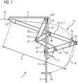
- a cabin 1 according to the invention with a revolving door 6 is shown in a top view.
- the cabin comprises a cabin wall 3, which has a cabin opening 5, this being only indicated.
- the cabin 1 further comprises a revolving door 6 with a door leaf 7 which can be pivoted between an open and a closed state.
- a crank mechanism 10 is provided, which is connected to the door leaf 7 and the cabin 1 and which guides the door leaf 7 on a curved guideway 18, 19 between the open and the closed state under the action of force.
- the door leaf 7 covers the cabin opening 5.
- crank gear 10 is, for example, of six members and is a flat crank gear 10.
- a crank gear 10 is also referred to as a coupling gear. In particular, it represents a special Watt-1 crank gear, which is described in more detail below. It should be noted that other crank mechanisms 10 can also be used. The invention is therefore not limited to the crank mechanism 10 described below.
- the six transmission links G1, G2, G3, G4, G5, G6 are linked to one another via six joints D1, D2, D3, D4, D5, D6.
- the gear links each have a fixed length.
- the frame G1, which acts as a reference element, is fixed or immobile with the cabin 1. In the closed state of the revolving door 6, the direction of the frame G1 coincides with the direction of the door leaf 7.
- the frame G1 is additionally oriented perpendicular to a side wall 4, the invention being not restricted to this.
- the frame G1 comprises two swivel joints, a drive swivel joint D1 and a further swivel joint D2.
- the swivel joint D2 is located on the side facing a side wall 4, the drive swivel joint D1 being on a side facing away from the side wall 4. Accordingly, the positions of these two rotary joints D1, D2 remain fixed or immobile during the movement of the transmission.
- the gear member G2 which functions as the drive member, is rotatably connected to the frame G1 via the swivel joint D1. At its end, which is not connected to the frame G1, there is a swivel joint D4 to which the coupling member G3 is rotatably connected.
- the coupling member G3 is connected to the revolving door 6 or to the door leaf 7 such that the movement and alignment of the coupling member G3 corresponds to the movement and alignment of the revolving door 6 in plan view.
- the length of the coupling member G3 is identical to a door leaf width t of the door leaf 7, so that in the Figure 1 in the present view or projection, the coupling member G3 with the door leaf 7 cannot be distinguished and the kinematics of the coupling member G3 match the kinematics of the door leaf 7.
- door leaf width t and length of coupling element G3 do not necessarily have to be identical.
- Both the coupling link G3 and the transmission link G2 have two rotary joints D3, D6 on their link sections.
- rotatable gear links G5 and G4 are linked, the ends of which remote from the swivel joints D3, D6 are rotatably connected to one another by a double swivel joint D5.
- a gear link G6 is also rotatably connected to the double swivel joint D5, which in turn is connected to the frame G1 via the swivel joint D2.
- the entire crank transmission 10 can be driven, for example, via the transmission link G2.
- the position of the gear members is determined via a variable, for example the angle of rotation indicated by ⁇ in the figure.
- ⁇ the angle of rotation indicated by ⁇ in the figure.
- all positions or orientations of the other transmission links G1, G3, G4, G5, G6 are uniquely determined, the position and orientation of the coupling link G3, that is to say of the door leaf 7, in particular.
- a locking mechanism with catch hooks can also be provided.
- the guideways 18, 19 of the door leaf 7 when the permitted rotation angles (0 ° ⁇ ⁇ 1 180 °) of the transmission element G2 are successively passed through are shown in FIG Figure 1 shown schematically.
- the outer guideway 19 describes the positions of the swivel joint D4 and thus a first side of the door leaf 7.
- the outer guideway 19 approximately corresponds to a semicircle.
- a cantilever of the outer guideway is approximately half the door leaf width t. This is therefore advantageously significantly less than in the case of a revolving door of the prior art, the projection of which corresponds to the door leaf width t, which is dealt with in more detail in the following figures in comparison with the prior art.
- the schematic representation of the inner guideway 18 describes the positions of the free side of the door leaf 7 facing away from the swivel joint D4.
- the inner guideway 18 is only approximately a straight line.
- the inner guideway 18 approaches the side wall 4 arranged towards the cabin wall. The smaller these distances become, the less space inside the cabin 1 is taken up by the kinematics of the door leaf 7. It is therefore particularly advantageous if the cabin opening 5 is located at the transition from the cabin wall 3 and an associated side wall 4, so that an inner guide track 18 close to the wall, as exemplified in FIG Figure 1 shown can be realized so that a passenger has as much space as possible inside the cabin 1.
- door seal 30 on the side of the door leaf 7 facing away from the swivel joint D4. This is suitable for covering the interior of the cabin 1 in an opaque manner if undesired gaps occur in the closed state, for example at the transition from cabin wall 3 and side wall 4.
- a grasping hand for closing or opening the revolving door 6 is thus advantageously not pinched, which increases the safety in handling the revolving door 6 or minimizes the risk of injury.
- a cabin 1 according to the invention is shown in plan view to visualize the kinematics of the revolving door when opening or closing.
- further useful elements are introduced within the cabin 1, here a washstand 70 and a toilet seat 80, which define predetermined boundary conditions for the optimization of an embodiment of a revolving door mechanism through their positions.
- the cabin 1 comprises a straight cabin wall 3 with a cabin opening 5 located there. Furthermore, the cabin 1 comprises a revolving door 6 with a door leaf 7, the positions of which including the open state and the closed state are shown by means of a sheet share 95, so that the guideway 18 , 19 of the revolving door 6 can be traced on the basis of the layers.
- the positions of the door leaf 7 correspond to that in Figure 1 Guide track 18, 19 described.
- the revolving door 6 covers the cabin opening 5, while in the open state the cabin 1 is accessible through the cabin opening 5. In this state, the revolving door 6 is located completely within the cabin 1 and thus does not block the aisle.
- the crank mechanism (not shown here) is set up in such a way that the guideway of the revolving door 6 takes place in the direction of a side wall 4 and not in the central region of the cabin 1.
- the cabin opening 5 is positioned in the transition from cabin wall 3 and an associated side wall 4 .
- the guide track or the sheet family 95 of the door leaf 7 advantageously runs at a short distance from the side wall 4.
- a circular area with a turning circle 90 is drawn in as an example, which results between the arrangement of the washstand 70 and the toilet seat 80 and the area swept by the door leaf 7.
- This turning circle 90 is particularly large due to the cabin 1 according to the invention with a revolving door 6 and crank mechanism 10, which becomes clear in the following comparison with a revolving door of the prior art.
- the revolving door 6 of the prior art comprises a door leaf 7 and opens or closes by rotation about a fixed pivot point 85.
- the swept area thus corresponds to a segment of a circle.
- the corresponding turning circle 90 which is available to a passenger in the interior of the cabin 1, is significantly smaller in comparison to the turning circle 90 of the cabin 1 according to the invention and is significantly less favorable in terms of location. This makes the advantage of the cabin 1 according to the invention with a revolving door 6 clear.
- Figure 4 and Figure 5 make analog to Figures 2 and 3 a comparison of the cabin 1 according to the invention with a cabin of the prior art.
- the other useful elements such as washstand 70 and a toilet seat 80 in different positions compared to Figure 2 and Figure 3 localized.
- the sheet family 95 of the revolving door 6 according to the invention Figure 4 is analogous to the sheet family 95 in Figure 2 .
- the turning circle resulting from the opening or closing movement of the revolving door 6 inside the cabin 1 in Figure 4 is correspondingly large compared to the resulting turning circle 90 in the cabin 1 of the prior art, see the corresponding cabin of the prior art in Figure 5 with the same arrangement of the useful elements, but the same revolving door 6 of the prior art as in Figure 3 described. It is also advantageous that the turning circle 90 is located centrally in the cabin 1 according to FIG. 4, while in the cabin of the prior art, that is to say, for example Figure 5 , this turning circle is located on the edge of cabin 1.
- the cabin 1 according to the invention thus results in greater comfort for the passenger when opening or closing the revolving door, since, as in the prior art, he does not have to dodge much in the cabin.
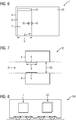
- a cabin 1 according to the invention is shown in a side view.
- the cabin 1 comprises a revolving door 6 with a door leaf 7 and is shown in the closed state.
- the cabin opening (not shown) is accordingly covered by the door leaf 6 and is located in the transition to a side wall 4.
- a ceiling area 20 is located in an upper part of the cabin 1.
- the crank mechanism 10 is advantageously accommodated in this ceiling area 20, so that the transmission members G1, G2, G3, G4, G5, G6 do not impair the passengers when opening or closing.
- the revolving door 6 further comprises a door handle 35 for manual actuation and a catch hook 40 for the locking mechanism. Alternatively, the door can be turned automatically.
- the door leaf width t preferably has a width of less than 1 m, more preferably less than 80 cm and particularly preferably 50 cm. For better stability, the door leaf 7 is guided at a lower end at a guide point 48.
- FIG. 7 A cabin arrangement 50 according to the invention is shown.
- the cabins 1 are arranged opposite one another, that is to say vis-à-vis, the cabins 1 being separated from one another by an aisle 54.
- the passage 54 has a passage width g.
- the aisle width g is the same size or approximately the same size as the door leaf width t of the door leaf 7.
- the cabins 1 according to the invention can advantageously be used, since their revolving doors 6 have a cantilevered arch with approximately the width when opening or closing half the door leaf width t. As a result, these revolving doors 6 do not impede one another and can be opened or closed simultaneously by passengers.
- aisle widths of 50 cm for example, aisle widths of 50 cm or of course more can be realized.
- Figure 8 shows a vehicle 100, preferably a rail vehicle, with an example of a cabin 1 according to the invention and a cabin arrangement 50. Alternatively, however, any number of cabins 1 and / or cabin arrangements 50 can also be incorporated in the vehicle 100.
- the cabin 1 offers an optimized utilization of the space provided by the crank mechanism 10 guiding the revolving door 6.
- both the area available for use can be expanded and the comfort during use can be increased.
Landscapes
- Engineering & Computer Science (AREA)
- Mechanical Engineering (AREA)
- Health & Medical Sciences (AREA)
- Epidemiology (AREA)
- General Health & Medical Sciences (AREA)
- Public Health (AREA)
- Aviation & Aerospace Engineering (AREA)
- Body Structure For Vehicles (AREA)
- Hinges (AREA)
- Support Devices For Sliding Doors (AREA)
Description
- Die vorliegende Erfindung betrifft eine Kabine mit Drehtür für ein Fahrzeug.
- Die Konstruktion von Kabinen wie beispielsweise Nasszellen in Fahrzeugen, insbesondere in Schienenfahrzeugen, ist durch ein eingeschränktes Platzangebot herausgefordert. Insbesondere wird durch die schließende Drehtür, die Kanten des Waschtisches und des WC-Sitzes der verbleibende freie Raum innerhalb der Kabine z. B. zur Drehung des Fahrgasts um die eigene Körperachse eingeschränkt.
- Typischerweise wurde bisher der eingeschränkte Wendekreis mit einer optimierten Anordnung aus Dreh- oder Schiebetür, dem Waschtisch und des WC-Sitzes gelöst. Eine Schiebetür ist in Bezug auf Größe des Wendekreises innerhalb der Kabine im Vorteil, da sie diesen während der platzüberstreichenden Schließbewegung nicht einschränkt. Nachteilig werden aber durch ihren Einsatz die Kabinen länger, um das Türblatt im geöffneten Zustand aufnehmen zu können. Drehtüren, die mit voller Türblattbreite in den Gang aufschlagen, sind ebenfalls unerwünscht, da sie den Bewegungsraum im Gang einschränken und es so zu unerwünschten Kollisionen kommen kann.
- Die Offenlegungsschrift
US 2010 / 0 237 193 A1 offenbart einen platzsparenden Türöffnungsmechanismus für eine Nasszelle eines Flugzeugs. Insbesondere beschreibt dieses Dokument eine Kabine mit Drehtür für ein Fahrzeug umfassend eine Kabinenwand mit einer Kabinenöffnung und eine Drehtür mit einem Türblatt, das zwischen einem geschlossenen Zustand und einem geöffneten Zustand schwenkbar ist. - Die Veröffentlichung "Laufschienenloses Garagentor" von G. Dittrich in IGM-Getriebesammlung, Nr. 603, 2000, Institut für Getriebetechnik und Maschinendynamik der RWTH Aachen lehrt ein sechsgliedriges Kurbelgetriebe zur Anwendung bei nach oben öffnenden Garagentoren, einhergehend mit einer Erhöhung des nutzbaren Volumens der Garage.
- Die Aufgabe besteht somit darin, eine Kabine mit einer Drehtür zu entwerfen, die den Wendekreis innerhalb der Kabine möglichst groß lässt und dabei nur in geringem Maße den Gang beim Öffnen blockiert.
- Die Erfindung wird durch die technischen Merkmale des Anspruchs 1 definiert. Erfindungsgemäß wird eine Kabine mit Drehtür für ein Fahrzeug zur Verfügung gestellt, welche eine Kabinenwand mit einer Kabinenöffnung aufweist. Die Kabine weist ferner eine Drehtür mit einem Türblatt auf, das zwischen einem geschlossenen Zustand und einem geöffneten Zustand schwenkbar ist. Erfindungsgemäß wird ein sechsgliedriges Kurbelgetriebe zur Verfügung gestellt, das mit dem Türblatt und der Kabine verbunden ist und das das Türblatt auf einer gekrümmten Führungsbahn zwischen dem geöffneten und dem geschlossen Zustand unter Krafteinwirkung führt, wobei im geschlossenen Zustand das Türblatt die Kabinenöffnung abdeckt.
- Eine solche Kabine hat den Vorteil, dass durch Wahl oder Konstruktion eines geeigneten, sechsgliedrigen Kurbelgetriebes zur Führung des Türblatts Führungsbahnen nach den jeweiligen Anforderungen an beispielsweise vergrößerten Wendekreis bzw. geringe auskragende Führungsbahn optimiert werden können. Diese Bahnen können über Getriebesynthese weiter verbessert werden.
- Das Kurbelgetriebe ist sechsgliedrig. Solche Kurbelgetriebe ermöglichen die Realisierung einer Vielzahl von Führungsbahnen zur Optimierung. Ein Kurbelgetriebe wird auch als Koppelgetriebe bezeichnet.
- Das Kurbelgetriebe ist bevorzugt ein Watt-1-Kurbelgetriebe, wobei ein Koppelglied des Watt-1-Kurbelgetriebes durch das Türblatt dargestellt wird. Mit einem solchen speziellen Watt-1-Kurbelgetriebe lässt sich eine Führungsbahn realisieren, die nur einen geringen auskragenden Bogen von etwa nur der Hälfte des Türblattdurchmessers aufweist. Das Türblatt steht auch vorteilhaft im geöffneten Zustand innerhalb der Kabine und versperrt den Gang nicht. Ferner lässt sich bei geeigneter Positionierung der Drehtür mit speziellem Watt-1-Kurbelgetriebe der Wendekreis für Fahrgäste innerhalb der Kabine vorteilhaft erhöhen, wodurch der Nutzerkomfort für den Fahrgast steigt.
- Das Türblatt kann am unteren Ende an einem Führungspunkt geführt werden. Dadurch wird die Stabilität der Drehtür beim Öffnen bzw. Schließen erhöht.
- Das Kurbelgetriebe und die zugehörigen Getriebeglieder sind vorteilhaft in einem Deckenbereich untergebracht. Dadurch wird eine Behinderung des Ganges bzw. der Benutzung der Drehtür durch herauskragende Getriebeglieder verringert.
- Die Kabinenöffnung der Kabinenwand befindet sich bevorzugt an einem Übergang von der Kabinenwand zu einer der Kabinenwand zugeordneten Seitenwand, wobei das Kurbelgetriebe mit dem Türblatt derart eingerichtet ist, dass die Drehbewegung des Türblatts in Richtung der Seitenwand erfolgt. Durch die Positionierung findet die Öffnungsbewegung mit minimalem Abstand zur Seitenwand statt. Dadurch kann die Bewegungsfreiheit für einen Fahrgast innerhalb der Kabine weiter erhöht werden.
- Im geöffneten Zustand liegt bevorzugt ein Quetschschutz zwischen Türblatt und Seitenwand vor. Dies kann dadurch erzielt werden, dass im geöffneten Zustand die Position des Türblatts von der Seitenwand absteht und somit einen Abstand zwischen Türblatt und Seitenwand entsteht. Ein manuelles Öffnen der Drehtür hat somit ein beispielsweise geringeres Verletzungsrisiko bzw. Quetschrisiko der Hand zur Folge.
- Weiterhin wird eine Kabinenanordnung mit zwei gegenüberliegenden Kabinen gemäß einer der obigen Ausführungen vorgeschlagen, wobei die Kabinenöffnungen durch einen zwischen den Kabinen befindlichen Gang voneinander getrennt sind. Durch die vorteilhafte geringe auskragende Bewegung in den Gang beim Öffnen bzw. Schließen der Drehtür können auch bei vorgegebener geringer zur Verfügung stehender Gangbreite demnach gegenüberliegende Kabinenanordnungen, auch häufig als Vis-à-Vis-Kabinenanordnungen bezeichnet, für Fahrzeuge, insbesondere für Schienenfahrzeuge, verwendet werden.
- Dabei kann die Gangbreite bevorzugt größer oder gleich der Türblattbreite des Türblatts sein. Da beispielsweise bei Watt-1-Kurbelgetrieben die auskragende Bewegung der Drehtür beim Öffnen bzw. Schließen ungefähr nur die Hälfte der Türblattbreite ausmacht, wäre somit die Gangbreite genügend groß, um ein zeitlich simultanes Öffnen bzw. Schließen zu gewährleisten.
- Ferner wird ein Fahrzeug umfassend mindestens eine Kabine nach den obigen Ausführungen und/oder mindestens eine Kabinenanordnung gemäß einem der obigen Ausführungen vorgeschlagen.
- Das Fahrzeug ist bevorzugt ein motorbetriebenes Fahrzeug, besonders bevorzugt ein Schienenfahrzeug. Insbesondere bei Schienenfahrzeugen können entsprechende Kabinentüren, z. B. für den Sanitärbereich vorgesehen sein. Das Fahrzeug umfasst auch andere Verkehrsmittel, wie zum Beispiel Busse, Schiffe und Flugzeuge. Auch dort können Kabinen, z. B. Sanitärbereiche, mittels der erfindungsgemäßen Drehtür verschlossen werden.
- Die erfindungsgemäße Drehtür kann sowohl manuell als auch automatisch betrieben werden.
- Die oben beschriebenen Eigenschaften, Merkmale und Vorteile dieser Erfindung sowie die Art und Weise, wie diese erreicht werden, werden klarer und deutlicher verständlich im Zusammenhang mit der folgenden Beschreibung der Ausführungsbeispiele, die im Zusammenhang mit den Zeichnungen näher erläutert werden. Es zeigen:
- Figur 1
- eine erfindungsgemäße Kabine mit einem ausgeführten speziellen Watt-1-Kurbelgetriebe,
- Figur 2
- eine erfindungsgemäße Kabine,
- Figur 3
- eine Kabine mit einer Drehtür des Standes der Technik,
- Figur 4
- eine erfindungsgemäße Kabine,
- Figur 5
- eine Kabine mit einer Drehtür des Standes der Technik,
- Figur 6
- eine erfindungsgemäße Kabine in Seitenansicht,
- Figur 7
- eine erfindungsgemäße Kabinenanordnung, und
- Figur 8
- ein erfindungsgemäßes Fahrzeug.
- In der
Figur 1 wird eine erfindungsgemäße Kabine 1 mit einer Drehtür 6 in Draufsicht gezeigt. Die Kabine umfasst eine Kabinenwand 3, die eine Kabinenöffnung 5 aufweist, wobei diese nur angedeutet ist. Die Kabine 1 umfasst ferner eine Drehtür 6 mit einem Türblatt 7, die zwischen einem geöffneten und einem geschlossenen Zustand schwenkbar ist. Ferner wird ein Kurbelgetriebe 10 zur Verfügung gestellt, das mit dem Türblatt 7 und der Kabine 1 verbunden ist und das das Türblatt 7 auf einer gekrümmten Führungsbahn 18, 19 zwischen dem geöffneten und dem geschlossen Zustand unter Krafteinwirkung führt. Im geschlossenen Zustand deckt das Türblatt 7 die Kabinenöffnung 5 ab. - Das ausgeführte Kurbelgetriebe 10 ist dabei beispielhaft sechsgliedrig ausgeführt und ist ein ebenes Kurbelgetriebe 10. Ein Kurbelgetriebe 10 wird auch als Koppelgetriebe bezeichnet. Es stellt im Besonderen ein spezielles Watt-1-Kurbelgetriebe dar, das im Weiteren näher beschrieben wird. Es sei angemerkt, dass auch andere Kurbelgetriebe 10 zum Einsatz kommen können. Die Erfindung ist somit nicht auf das im Folgenden beschriebene Kurbelgetriebe 10 beschränkt.
- Die sechs Getriebeglieder G1, G2, G3, G4, G5, G6 sind dabei über sechs Gelenke D1, D2, D3, D4, D5, D6 miteinander verknüpft. Die Getriebeglieder haben jeweils eine feste Länge. Fest bzw. immobil mit der Kabine 1 gelagert ist das Gestell G1, das als Bezugsglied fungiert. Im geschlossenen Zustand der Drehtür 6 fällt die Richtung des Gestells G1 mit der Richtung des Türblatts 7 überein. Das Gestell G1 ist zusätzlich senkrecht zu einer Seitenwand 4 orientiert, wobei die Erfindung nicht darauf beschränkt ist.
- Das Gestell G1 umfasst zwei Drehgelenke, ein Antriebsdrehgelenk D1 und ein weiteres Drehgelenk D2. Das Drehgelenk D2 befindet sich dabei auf der zu einer Seitenwand 4 zugewandten Seite, wobei das Antriebsdrehgelenk D1 sich auf einer zu der Seitenwand 4 abgewandten Seite befindet. Entsprechend bleiben auch die Positionen dieser beiden Drehgelenke D1, D2 während der Bewegung des Getriebes fest bzw. immobil.
- Über das Drehgelenk D1 mit dem Gestell G1 drehbar verbunden ist das Getriebeglied G2, das als Antriebsglied fungiert. An dessen Ende, das nicht mit dem Gestell G1 verbunden ist, befindet sich ein Drehgelenk D4, an dem das Koppelglied G3 drehbar verbunden ist. Das Koppelglied G3 ist mit der Drehtür 6 bzw. mit dem Türblatt 7 derart verbunden, dass die Bewegung und Ausrichtung des Koppelglieds G3 der Bewegung und Ausrichtung der Drehtür 6 in der Draufsicht entspricht. In diesem konkreten Beispiel ist die Länge des Koppelglieds G3 mit einer Türblattbreite t des Türblatts 7 identisch, so dass in der
Figur 1 bei der vorliegenden Ansicht bzw. Projektion das Koppelglied G3 mit dem Türblatt 7 nicht unterscheidbar ist und die Kinematik des Koppelglieds G3 mit der Kinematik des Türblatts 7 übereinstimmt. Grundsätzlich müssen Türblattbreite t und Länge des Koppelglieds G3 nicht zwingend identisch sein. - Sowohl das Koppelglied G3 als auch das Getriebeglied G2 weisen auf ihren Gliederabschnitten zwei Drehgelenke D3, D6 auf.
- An diesen Drehgelenken D3, D6 sind drehbare Getriebeglieder G5 und G4 verknüpft, deren von den Drehgelenken D3, D6 abgewandten Enden miteinander durch ein Doppeldrehgelenk D5 drehbar verbunden sind. Mit dem Doppeldrehgelenk D5 drehbar verbunden ist ferner ein Getriebeglied G6 das, wiederum mit dem Gestell G1 über das Drehgelenk D2 verbunden ist. Die Längenverhältnisse und die Positionen der Drehgelenke auf den jeweiligen Gelenken sind nicht beliebig, sondern gehorchen bestimmten Längenverhältnissen, so dass die Bewegung des Koppelglieds G3 erfolgen kann.
- Die Positionen der Drehgelenke D1, D2, D3, D4, D5, D6 und Längenverhältnisse können dabei der Figur entnommen werden. Zur besseren Reproduzierbarkeit werden diese Längenverhältnisse auch numerisch angegeben, wobei zur Dokumentierung dieser Längenverhältnisse die Abstände zwischen zwei Drehgelenken DX und DY als d (DX, DY) bezeichnet. Bei Normierung des kürzesten Abstandes, das ist der Abstand zwischen Drehgelenk D1 und Drehgelenk D3, d. h. d (D1, D3) = 1, folgen entsprechend: d (D1, D4) = 2, 968; d (D1, D2) = 3,125; d (D4, D6) = 2,656; d (D3, D5) = 2,031; d (D5, D2) = 2,25; d (D5, D6) = 1,387.
- Das gesamte Kurbelgetriebe 10 lässt sich beispielsweise über das Getriebeglied G2 antreiben. Die Position der Getriebeglieder ist über eine Variable bestimmt, beispielsweise den in der Figur mit α indizierten Drehwinkel. Zu jedem festen Winkelwert des Getriebegliedes G2 sind somit alle Positionen bzw. Orientierungen der anderen Getriebeglieder G1, G3, G4, G5, G6 eindeutig bestimmt, wobei insbesondere die Position und Orientierung des Koppelglieds G3, also des Türblatts 7 eindeutig daraus hervorgeht.
- Der Drehwinkel α des Getriebegliedes G2 bezogen auf das Gestell G1 wird vorteilhaft auf Werte von 0°≤α≤180°beschränkt, wobei α = 0° den geschlossenen Zustand der Drehtür 6 bezeichnet. Dann ist das Türblatt 7 parallel zum Gestell G1 ausgerichtet und deckt die Kabinenöffnung 5 entsprechend ab. Aufnahmeglieder 45 an Koppelglied G3 und an Kabinenwand 3 erzeugen ein Einrasten des Koppelgliedes G3 bei α = 0°. Hierfür kann ferner ein Schließmechanismus mit Fanghaken bereitgestellt werden.
- Der geöffnete Zustand entspricht α=180°. Die Führungsbahnen 18, 19 des Türblatts 7 bei sukzessivem Durchlaufen der erlaubten Drehwinkel (0°≤α≤180°) des Getriebegliedes G2 sind in
Figur 1 schematisch dargestellt. Dabei beschreibt die äußere Führungsbahn 19 die Positionen des Drehgelenks D4 und damit einer ersten Seite des Türblatts 7. Näherungsweise entspricht dabei die äußere Führungsbahn 19 einem Halbkreis. Dabei ist eine Auskragung der äußeren Führungsbahn etwa halb so groß wie die Türblattbreite t. Dies ist also vorteilhaft deutlich geringer als bei einer Drehtür des Standes der Technik, deren Auskragung der Türblattbreite t entspricht, was in den folgenden Figuren im Vergleich zum Stand der Technik näher behandelt wird. - Die schematische Darstellung der inneren Führungsbahn 18 beschreibt die Positionen der zum Drehgelenk D4 abgewandten freien Seite des Türblatts 7. Die innere Führungsbahn 18 ist dabei nur näherungsweise eine Gerade. Die innere Führungsbahn 18 nähert sich dabei der zur Kabinenwand angeordneten Seitenwand 4 an. Je geringer diese Abstände werden, desto weniger Raum im Inneren der Kabine 1 wird durch die Kinematik des Türblatts 7 eingenommen. Es ist daher besonders vorteilhaft, wenn die Kabinenöffnung 5 sich am Übergang von Kabinenwand 3 und einer zugeordneten Seitenwand 4 befindet, so dass eine wandnahe innere Führungsbahn 18 wie beispielhaft in
Figur 1 gezeigt realisiert werden kann, so dass ein Fahrgast im Inneren der Kabine 1 möglichst viel Platz zur Verfügung hat. - An der vom Drehgelenk D4 abgewandten Seite des Türblatts 7 befindet sich eine Türdichtung 30. Diese ist dafür geeignet, das Innere der Kabine 1 blickdicht abzudecken, falls im geschlossenen Zustand unerwünschte Spalte entstehen, beispielsweise am Übergang von Kabinenwand 3 und Seitenwand 4.
- Ferner kann vorteilhaft die finale Position des Türblatts 7, also bei α=180°, nicht parallel zur Seitenwand 4 ausgerichtet sein, so dass das Türblatt 7 etwas von der Seitenwand 4 absteht. Dadurch entsteht im geöffneten Zustand ein Spalt, der als Quetschschutz 32 vorteilhaft agiert. Eine umgreifende Hand zum Schließen oder Öffnen der Drehtür 6 wird somit vorteilhaft nicht eingeklemmt, wodurch die Sicherheit im Umgang mit der Drehtür 6 erhöht wird bzw. das Verletzungsrisiko minimiert wird.
- In den
Figuren 2-5 wird die vorteilhafte Kinematik beim Schließen bzw. Öffnen der erfindungsgemäßen Drehtür 6 gegenüber einer Drehtür des Standes der Technik demonstriert. - In der
Figur 2 ist eine erfindungsgemäße Kabine 1 in Draufsicht dargestellt zur Visualisierung der Kinematik der Drehtür beim Öffnen bzw. Schließen. Beispielhaft sind innerhalb der Kabine 1 weitere Nutzelemente eingebracht, hier ein Waschtisch 70 sowie ein WC-Sitz 80, die durch ihre Positionen vorgegebene Randbedingungen für die Optimierung einer Ausgestaltung eines Drehtürmechanismus definieren. - Die Kabine 1 umfasst eine gerade Kabinenwand 3 mit einer dort befindlichen Kabinenöffnung 5. Ferner umfasst die Kabine 1 eine Drehtür 6 mit einem Türblatt 7, deren Positionen einschließlich des geöffneten Zustands und des geschlossenen Zustands mittels einer Lagenschar 95 dargestellt ist, so dass die Führungsbahn 18, 19 der Drehtür 6 anhand der Lagen nachvollzogen werden kann. Die Lagen des Türblatts 7 entsprechen der in
Figur 1 beschriebenen Führungsbahn 18, 19. Im geschlossenen Zustand deckt die Drehtür 6 die Kabinenöffnung 5 ab, während im geöffneten Zustand die Kabine 1 durch die Kabinenöffnung 5 begehbar ist. In diesem Zustand befindet sich die Drehtür 6 vollständig innerhalb der Kabine 1 und versperrt somit nicht den Gang. - Das Kurbelgetriebe (hier nicht eingezeichnet) ist dabei derart eingerichtet, dass die Führungsbahn der Drehtür 6 in Richtung einer Seitenwand 4 erfolgt und nicht in den mittigen Bereich der Kabine 1. Zudem ist die Kabinenöffnung 5 im Übergang von Kabinenwand 3 und einer zugeordneten Seitenwand 4 positioniert. Dadurch verläuft die Führungsbahn bzw. die Lagenschar 95 des Türblatts 7 vorteilhaft mit kurzem Abstand zur Seitenwand 4.
- Zur Charakterisierung des für einen Fahrgast innerhalb der Kabine 1 zur Verfügung stehenden Raumbereichs wird beispielhaft eine Kreisfläche mit einem Wendekreis 90 eingezeichnet, die sich zwischen der Anordnung des Waschtischs 70 und des WC-Sitzes 80 sowie der vom Türblatt 7 überstrichenen Fläche ergibt. Dieser Wendekreis 90 ist durch die erfindungsgemäße Kabine 1 mit Drehtür 6 und Kurbelgetriebe 10 besonders groß, was im folgenden Vergleich mit einer Drehtür des Standes der Technik deutlich wird.
- In der
Figur 3 ist zum Vergleich eine Kabine 1 mit einer Drehtür 6 des Standes de Technik dargestellt. Die Positionierungen der weiteren Nutzelemente, also des Waschtischs 70 bzw. des WC-Sitzes 80 sind dabei identisch zuFigur 2 ausgeführt. - Die Drehtür 6 des Standes der Technik umfasst ein Türblatt 7 und öffnet bzw. schließt durch Rotation um einen festen Drehpunkt 85. Somit entspricht die überstrichene Fläche einem Kreisausschnitt. Der entsprechende Wendekreis 90, der einem Fahrgast im Inneren der Kabine 1 zur Verfügung steht, ist im Vergleich zum Wendekreis 90 der erfindungsgemäßen Kabine 1 deutlich kleiner und von der Lage her deutlich ungünstiger. Dadurch wird der Vorteil der erfindungsgemäßen Kabine 1 mit Drehtür 6 deutlich gemacht.
-
Figur 4 und Figur 5 stellen analog zuFigur 2 und 3 einen Vergleich der erfindungsgemäßen Kabine 1 mit einer Kabine des Standes der Technik dar. In diesen Ausführungsformen sind die weiteren Nutzelemente wie Waschtisch 70 sowie ein WC-Sitz 80 an unterschiedlichen Positionen im Vergleich zuFigur 2 und Figur 3 lokalisiert. Die Lagenschar 95 der erfindungsgemäßen Drehtür 6 inFigur 4 ist dabei analog zu der Lagenschar 95 inFigur 2 . - Der sich aus der Öffnungs- oder Schließbewegung der Drehtür 6 ergebende Wendekreis im Inneren der Kabine 1 in
Figur 4 ist entsprechend groß im Vergleich zum sich ergebenen Wendekreis 90 in der Kabine 1 des Standes der Technik, siehe dazu die entsprechende Kabine des Standes der Technik inFigur 5 bei gleicher Anordnung der Nutzelemente, aber gleicher Drehtür 6 des Standes der Technik wie inFigur 3 beschrieben. Vorteilhaft ergibt sich zudem, dass der Wendekreis 90 sich gemäß Figur 4 zentral in der Kabine 1 befindet, während bei der Kabine des Standes der Technik, also beispielsweise beiFigur 5 , dieser Wendekreis sich am Rand der Kabine 1 befindet. Für den Fahrgast ergibt sich durch die erfindungsgemäße Kabine 1 somit ein höherer Komfort beim Öffnen oder Schließen der Drehtür, da er nicht wie beim Stand der Technik in der Kabine stark ausweichen muss. - In
Figur 6 ist eine erfindungsgemäße Kabine 1 in Seitenansicht gezeigt. Die Kabine 1 umfasst wie in den vorigen Figuren eine Drehtür 6 mit einem Türblatt 7 und ist im geschlossenen Zustand dargestellt. Die Kabinenöffnung (nicht eingezeichnet) wird also entsprechend von dem Türblatt 6 abgedeckt und ist im Übergang zu einer Seitenwand 4 lokalisiert. In einem oberen Teil der Kabine 1 befindet sich ein Deckenbereich 20. In diesem Deckenbereich 20 ist vorteilhaft das Kurbelgetriebe 10 untergebracht, so dass die Getriebeglieder G1, G2, G3, G4, G5, G6 beim Öffnen oder Schließen die Fahrgäste nicht beeinträchtigen. - Die Drehtür 6 umfasst ferner einen Türgriff 35 zur manuellen Betätigung sowie einen Fanghaken 40 für den Schließmechanismus. Die Drehung der Tür kann alternativ auch automatisch erfolgen. Die Türblattbreite t weist bevorzugt eine Breite von weniger als 1 m auf, noch bevorzugter weniger als 80 cm und besonders bevorzugt 50 cm. Zur besseren Stabilität wird das Türblatt 7 an einem unteren Ende an einem Führungspunkt 48 geführt.
- In
Figur 7 wird eine erfindungsgemäße Kabinenanordnung 50 gezeigt. Dabei sind die Kabinen 1 gegenüber, also vis-à-vis, angeordnet, wobei die Kabinen 1 durch einen Gang 54 voneinander getrennt sind. Der Gang 54 weist eine Gangbreite g auf. Die Gangbreite g ist dabei gleich groß bzw. in etwa gleich groß wie die Türblattbreite t des Türblatts 7. Bei dieser Gangbreite g können vorteilhaft die erfindungsgemäßen Kabinen 1 verwendet werden, da deren Drehtüren 6 bei Öffnen bzw. Schließen einen auskragenden Bogen aufweisen mit etwa der halben Türblattbreite t. Dadurch behindern sich diese Drehtüren 6 nicht und können simultan von Fahrgästen geöffnet bzw. geschlossen werden. Für Türblattbreiten t von beispielsweise 50 cm können somit Gangbreiten von 50 cm oder natürlich auch mehr realisiert werden. -
Figur 8 zeigt ein Fahrzeug 100, bevorzugt ein Schienenfahrzeug, mit beispielhaft einer erfindungsgemäßen Kabine 1 und einer Kabinenanordnung 50. Alternativ können aber auch beliebig viele Kabinen 1 und/oder Kabinenanordnungen 50 im Fahrzeug 100 eingebracht sein. - Zusammengefasst bietet die erfindungsgemäße Kabine 1 eine optimierte Ausnutzung der zur Verfügung gestellten Räumlichkeiten durch das die Drehtür 6 führende Kurbelgetriebe 10. Dadurch kann sowohl die zur Nutzung zur Verfügung stehende Fläche erweitert werden als such der Komfort bei der Benutzung gesteigert werden.
Claims (9)
- Eine Kabine (1) mit Drehtür (6) für ein Fahrzeug (100) umfassend:- eine Kabinenwand (3) mit einer Kabinenöffnung (5);- eine Drehtür (6) mit einem Türblatt (7), das zwischen einem geschlossenen Zustand und einem geöffneten Zustand schwenkbar ist;dadurch gekennzeichnet, dass sie- ein Kurbelgetriebe (10) umfasst, das mit der Kabine (1) und dem Türblatt (7) verbunden ist, das das Türblatt (7) auf gekrümmten Führungsbahnen (18, 19) zwischen dem geöffneten und dem geschlossen Zustand unter Krafteinwirkung führt, wobei im geschlossenen Zustand das Türblatt (7) die Kabinenöffnung (5) abdeckt, wobei das Kurbelgetriebe (10) sechsgliedrig ist.
- Eine Kabine (1) nach Anspruch 1, wobei das Kurbelgetriebe (10) ein Watt-l-Kurbelgetriebe ist, wobei ein Koppelglied (G3) des Watt-l-Kurbelgetriebes durch das Türblatt (7) dargestellt wird.
- Eine Kabine (1) nach einem der vorherigen Ansprüche, wobei das Türblatt (7) an einem unteren Ende an einem Führungspunkt (48) geführt wird.
- Eine Kabine (1) nach einem der vorherigen Ansprüche, wobei das Kurbelgetriebe (10) und die zugehörigen Getriebeglieder (G1, G2, G3, G4, G5, G6) in einem Deckenbereich (20) untergebracht sind.
- Eine Kabine (1) nach einem der vorherigen Ansprüche, wobei sich die Kabinenöffnung (5) der Kabinenwand (3) an einem Übergang von Kabinenwand (3) und einer der Kabinenwand (3) zugeordneten Seitenwand (4) befindet, wobei das Kurbelgetriebe (10) mit Türblatt (7) derart eingerichtet ist, dass die Drehbewegung des Türblatts (7) in Richtung der Seitenwand (4) erfolgt.
- Eine Kabine (1) nach einem der vorherigen Ansprüche, wobei im geöffneten Zustand ein Quetschschutz (32) zwischen Türblatt (7) und Seitenwand (4) vorliegt.
- Eine Kabinenanordnung (50) mit zwei gegenüberliegenden Kabinen (1) gemäß einem der vorherigen Ansprüche, wobei die Kabinenöffnungen (5) durch einen zwischen den Kabinen befindlichen Gang (54) voneinander getrennt sind.
- Eine Kabinenanordnung (50) gemäß Anspruch 7, wobei die Gangbreite (g) größer oder gleich der Türblattbreite (t) des Türblatts (7) ist.
- Ein Fahrzeug (100) umfassend mindestens eine Kabine (1) nach einem der Ansprüche 1 bis 8 und/oder umfassend mindestens eine Kabinenanordnung (50) nach einem der Ansprüche 7 bis 8.
Applications Claiming Priority (2)
| Application Number | Priority Date | Filing Date | Title |
|---|---|---|---|
| DE102016212380.7A DE102016212380B3 (de) | 2016-07-07 | 2016-07-07 | Kabine mit Drehtür |
| PCT/EP2017/065012 WO2018007141A1 (de) | 2016-07-07 | 2017-06-20 | Kabine mit drehtür |
Publications (2)
| Publication Number | Publication Date |
|---|---|
| EP3452356A1 EP3452356A1 (de) | 2019-03-13 |
| EP3452356B1 true EP3452356B1 (de) | 2020-05-20 |
Family
ID=59269992
Family Applications (1)
| Application Number | Title | Priority Date | Filing Date |
|---|---|---|---|
| EP17734664.0A Active EP3452356B1 (de) | 2016-07-07 | 2017-06-20 | Kabine mit drehtür |
Country Status (6)
| Country | Link |
|---|---|
| EP (1) | EP3452356B1 (de) |
| CN (1) | CN210116506U (de) |
| DE (1) | DE102016212380B3 (de) |
| ES (1) | ES2808331T3 (de) |
| RU (1) | RU190358U1 (de) |
| WO (1) | WO2018007141A1 (de) |
Families Citing this family (3)
| Publication number | Priority date | Publication date | Assignee | Title |
|---|---|---|---|---|
| DE102016217722A1 (de) | 2016-09-16 | 2018-03-22 | Siemens Aktiengesellschaft | Sanitärkabine mit Hocktoilette und Kompaktvakuumtechnik überflur |
| FR3076791B1 (fr) * | 2018-01-18 | 2022-04-01 | Faiveley Transp Tours | Porte a emprise reduite pour vehicule de transport, cloison coupe-feu et vehicule ainsi equipes |
| CN110011203B (zh) * | 2019-04-28 | 2024-11-19 | 广东电网有限责任公司广州供电局 | 开关柜及其散热机构 |
Family Cites Families (9)
| Publication number | Priority date | Publication date | Assignee | Title |
|---|---|---|---|---|
| JPS58195769U (ja) * | 1982-06-24 | 1983-12-26 | 株式会社能登 | 一枚扉 |
| AT387619B (de) * | 1986-03-24 | 1989-02-27 | Ife Gmbh | Antriebsvorrichtung fuer tueren, insbesondere fuer fahrzeugtueren |
| JP3673115B2 (ja) * | 1998-12-28 | 2005-07-20 | 株式会社オートドアー技研 | スライド・スイング式ドア装置 |
| RU2211295C1 (ru) * | 2002-02-08 | 2003-08-27 | Открытое акционерное общество "Инновационная фирма "КМТ" | Устройство для перемещения сдвижной двери |
| US7987331B2 (en) | 2007-11-15 | 2011-07-26 | Infineon Technologies Ag | Method and circuit for protection of sensitive data in scan mode |
| US7997028B2 (en) * | 2008-02-28 | 2011-08-16 | Airbus Deutschland Gmbh | Internal swivel door for compartment of a vehicle |
| JP5371500B2 (ja) * | 2009-03-17 | 2013-12-18 | 株式会社ジャムコ | 航空機用化粧室のドア構造 |
| CN202966330U (zh) * | 2012-12-21 | 2013-06-05 | 河北株丕特玻璃钢制品有限公司 | 一种残疾人玻璃钢卫生间 |
| CN204728882U (zh) * | 2015-04-24 | 2015-10-28 | 云南仨得科技有限公司 | 一种弧形防护舱防夹驱动装置 |
-
2016
- 2016-07-07 DE DE102016212380.7A patent/DE102016212380B3/de not_active Expired - Fee Related
-
2017
- 2017-06-20 RU RU2019101626U patent/RU190358U1/ru active
- 2017-06-20 WO PCT/EP2017/065012 patent/WO2018007141A1/de not_active Ceased
- 2017-06-20 ES ES17734664T patent/ES2808331T3/es active Active
- 2017-06-20 CN CN201790001019.5U patent/CN210116506U/zh not_active Expired - Fee Related
- 2017-06-20 EP EP17734664.0A patent/EP3452356B1/de active Active
Non-Patent Citations (1)
| Title |
|---|
| None * |
Also Published As
| Publication number | Publication date |
|---|---|
| ES2808331T3 (es) | 2021-02-26 |
| DE102016212380B3 (de) | 2017-10-19 |
| RU190358U1 (ru) | 2019-06-28 |
| CN210116506U (zh) | 2020-02-28 |
| WO2018007141A1 (de) | 2018-01-11 |
| EP3452356A1 (de) | 2019-03-13 |
Similar Documents
| Publication | Publication Date | Title |
|---|---|---|
| EP0465785B1 (de) | Vorrichtung zum Bewegen einer Flugzeugtür | |
| AT500017B1 (de) | Schwenkschiebetür für fahrzeuge | |
| DE102016212380B3 (de) | Kabine mit Drehtür | |
| EP0794310B1 (de) | Faltflügeltür | |
| EP3656960B1 (de) | Stellglied und lagerungseinrichtung für eine klappe | |
| DE102018130527B3 (de) | Türanordnung mit Gelenkarm, Flugzeugbereich mit Türanordnung und Flugzeug mit Flugzeugbereich | |
| DE19725677A1 (de) | Fenster, Tür od. dgl. an Wohnwagen, Wohnmobilen oder sonstigen Fahrzeugen | |
| EP1056920B1 (de) | Karusseltür mit nachtabschluss | |
| EP2540616B1 (de) | Schließmechanismus für eine mit Kraftunterstützung schließende Schiebetüre | |
| DE10237492B3 (de) | Vorrichtung zum Öffnen und/oder Schließen eines Flügels relativ zu einem Rahmenstock | |
| DE4211861C2 (de) | Karusselltür | |
| DE20004973U1 (de) | Schwenktürantrieb | |
| DE19752567A1 (de) | Vorrichtung zur Heizung, Belüftung und/oder Klimatisierung, insbesondere für den Fahrgastraum eines Kraftfahrzeugs | |
| DE102012004441B4 (de) | Türanlage für ein Einbaumodul in einem Flugzeug sowie ein Einbaumodul für ein Flugzeug | |
| EP3184722A1 (de) | Faltflügeltor mit innenliegender antriebs- und positionierungsvorrichtung | |
| EP3510220B1 (de) | Rastscharnier | |
| DE10261157A1 (de) | Automatische Falttüranlage | |
| EP2135791A1 (de) | Schienenfahrzeug | |
| DE19937364B4 (de) | Karusselltür | |
| AT393402B (de) | Aus einer abzudeckenden oeffnung auf einer gekruemmten bahn herausbewegbare abdeckung | |
| AT401082B (de) | Ein- oder zweiflügelige schiebe-, schwenkschiebe- oder taschentür | |
| DE3125359A1 (de) | Halterung fuer faltbare fluegelanordnungen, insbesondere fuer falttueren an moebelstuecken | |
| DE60211819T2 (de) | Vorrichtung zum Öffnen und Schliessen einer Dreh-Schiebetür für Kraftfahrzeuge | |
| DE202010004097U1 (de) | Schiebewand | |
| DE3027872A1 (de) | Drehkurbeltrieb |
Legal Events
| Date | Code | Title | Description |
|---|---|---|---|
| STAA | Information on the status of an ep patent application or granted ep patent |
Free format text: STATUS: UNKNOWN |
|
| STAA | Information on the status of an ep patent application or granted ep patent |
Free format text: STATUS: THE INTERNATIONAL PUBLICATION HAS BEEN MADE |
|
| PUAI | Public reference made under article 153(3) epc to a published international application that has entered the european phase |
Free format text: ORIGINAL CODE: 0009012 |
|
| STAA | Information on the status of an ep patent application or granted ep patent |
Free format text: STATUS: REQUEST FOR EXAMINATION WAS MADE |
|
| 17P | Request for examination filed |
Effective date: 20181207 |
|
| AK | Designated contracting states |
Kind code of ref document: A1 Designated state(s): AL AT BE BG CH CY CZ DE DK EE ES FI FR GB GR HR HU IE IS IT LI LT LU LV MC MK MT NL NO PL PT RO RS SE SI SK SM TR |
|
| AX | Request for extension of the european patent |
Extension state: BA ME |
|
| DAV | Request for validation of the european patent (deleted) | ||
| DAX | Request for extension of the european patent (deleted) | ||
| RIC1 | Information provided on ipc code assigned before grant |
Ipc: B61D 35/00 20060101AFI20191202BHEP Ipc: B60R 15/00 20060101ALI20191202BHEP Ipc: B61D 19/02 20060101ALI20191202BHEP |
|
| GRAP | Despatch of communication of intention to grant a patent |
Free format text: ORIGINAL CODE: EPIDOSNIGR1 |
|
| STAA | Information on the status of an ep patent application or granted ep patent |
Free format text: STATUS: GRANT OF PATENT IS INTENDED |
|
| INTG | Intention to grant announced |
Effective date: 20200120 |
|
| GRAS | Grant fee paid |
Free format text: ORIGINAL CODE: EPIDOSNIGR3 |
|
| GRAA | (expected) grant |
Free format text: ORIGINAL CODE: 0009210 |
|
| STAA | Information on the status of an ep patent application or granted ep patent |
Free format text: STATUS: THE PATENT HAS BEEN GRANTED |
|
| AK | Designated contracting states |
Kind code of ref document: B1 Designated state(s): AL AT BE BG CH CY CZ DE DK EE ES FI FR GB GR HR HU IE IS IT LI LT LU LV MC MK MT NL NO PL PT RO RS SE SI SK SM TR |
|
| REG | Reference to a national code |
Ref country code: GB Ref legal event code: FG4D Free format text: NOT ENGLISH |
|
| REG | Reference to a national code |
Ref country code: CH Ref legal event code: EP |
|
| REG | Reference to a national code |
Ref country code: DE Ref legal event code: R096 Ref document number: 502017005393 Country of ref document: DE |
|
| REG | Reference to a national code |
Ref country code: AT Ref legal event code: REF Ref document number: 1272425 Country of ref document: AT Kind code of ref document: T Effective date: 20200615 |
|
| REG | Reference to a national code |
Ref country code: LT Ref legal event code: MG4D |
|
| REG | Reference to a national code |
Ref country code: NL Ref legal event code: MP Effective date: 20200520 |
|
| PG25 | Lapsed in a contracting state [announced via postgrant information from national office to epo] |
Ref country code: PT Free format text: LAPSE BECAUSE OF FAILURE TO SUBMIT A TRANSLATION OF THE DESCRIPTION OR TO PAY THE FEE WITHIN THE PRESCRIBED TIME-LIMIT Effective date: 20200921 Ref country code: NO Free format text: LAPSE BECAUSE OF FAILURE TO SUBMIT A TRANSLATION OF THE DESCRIPTION OR TO PAY THE FEE WITHIN THE PRESCRIBED TIME-LIMIT Effective date: 20200820 Ref country code: IS Free format text: LAPSE BECAUSE OF FAILURE TO SUBMIT A TRANSLATION OF THE DESCRIPTION OR TO PAY THE FEE WITHIN THE PRESCRIBED TIME-LIMIT Effective date: 20200920 Ref country code: GR Free format text: LAPSE BECAUSE OF FAILURE TO SUBMIT A TRANSLATION OF THE DESCRIPTION OR TO PAY THE FEE WITHIN THE PRESCRIBED TIME-LIMIT Effective date: 20200821 Ref country code: FI Free format text: LAPSE BECAUSE OF FAILURE TO SUBMIT A TRANSLATION OF THE DESCRIPTION OR TO PAY THE FEE WITHIN THE PRESCRIBED TIME-LIMIT Effective date: 20200520 Ref country code: SE Free format text: LAPSE BECAUSE OF FAILURE TO SUBMIT A TRANSLATION OF THE DESCRIPTION OR TO PAY THE FEE WITHIN THE PRESCRIBED TIME-LIMIT Effective date: 20200520 Ref country code: LT Free format text: LAPSE BECAUSE OF FAILURE TO SUBMIT A TRANSLATION OF THE DESCRIPTION OR TO PAY THE FEE WITHIN THE PRESCRIBED TIME-LIMIT Effective date: 20200520 |
|
| PG25 | Lapsed in a contracting state [announced via postgrant information from national office to epo] |
Ref country code: BG Free format text: LAPSE BECAUSE OF FAILURE TO SUBMIT A TRANSLATION OF THE DESCRIPTION OR TO PAY THE FEE WITHIN THE PRESCRIBED TIME-LIMIT Effective date: 20200820 Ref country code: HR Free format text: LAPSE BECAUSE OF FAILURE TO SUBMIT A TRANSLATION OF THE DESCRIPTION OR TO PAY THE FEE WITHIN THE PRESCRIBED TIME-LIMIT Effective date: 20200520 Ref country code: RS Free format text: LAPSE BECAUSE OF FAILURE TO SUBMIT A TRANSLATION OF THE DESCRIPTION OR TO PAY THE FEE WITHIN THE PRESCRIBED TIME-LIMIT Effective date: 20200520 Ref country code: LV Free format text: LAPSE BECAUSE OF FAILURE TO SUBMIT A TRANSLATION OF THE DESCRIPTION OR TO PAY THE FEE WITHIN THE PRESCRIBED TIME-LIMIT Effective date: 20200520 |
|
| PG25 | Lapsed in a contracting state [announced via postgrant information from national office to epo] |
Ref country code: NL Free format text: LAPSE BECAUSE OF FAILURE TO SUBMIT A TRANSLATION OF THE DESCRIPTION OR TO PAY THE FEE WITHIN THE PRESCRIBED TIME-LIMIT Effective date: 20200520 Ref country code: AL Free format text: LAPSE BECAUSE OF FAILURE TO SUBMIT A TRANSLATION OF THE DESCRIPTION OR TO PAY THE FEE WITHIN THE PRESCRIBED TIME-LIMIT Effective date: 20200520 |
|
| PG25 | Lapsed in a contracting state [announced via postgrant information from national office to epo] |
Ref country code: EE Free format text: LAPSE BECAUSE OF FAILURE TO SUBMIT A TRANSLATION OF THE DESCRIPTION OR TO PAY THE FEE WITHIN THE PRESCRIBED TIME-LIMIT Effective date: 20200520 Ref country code: SM Free format text: LAPSE BECAUSE OF FAILURE TO SUBMIT A TRANSLATION OF THE DESCRIPTION OR TO PAY THE FEE WITHIN THE PRESCRIBED TIME-LIMIT Effective date: 20200520 Ref country code: DK Free format text: LAPSE BECAUSE OF FAILURE TO SUBMIT A TRANSLATION OF THE DESCRIPTION OR TO PAY THE FEE WITHIN THE PRESCRIBED TIME-LIMIT Effective date: 20200520 Ref country code: RO Free format text: LAPSE BECAUSE OF FAILURE TO SUBMIT A TRANSLATION OF THE DESCRIPTION OR TO PAY THE FEE WITHIN THE PRESCRIBED TIME-LIMIT Effective date: 20200520 Ref country code: CZ Free format text: LAPSE BECAUSE OF FAILURE TO SUBMIT A TRANSLATION OF THE DESCRIPTION OR TO PAY THE FEE WITHIN THE PRESCRIBED TIME-LIMIT Effective date: 20200520 |
|
| REG | Reference to a national code |
Ref country code: CH Ref legal event code: PL |
|
| REG | Reference to a national code |
Ref country code: DE Ref legal event code: R097 Ref document number: 502017005393 Country of ref document: DE |
|
| PG25 | Lapsed in a contracting state [announced via postgrant information from national office to epo] |
Ref country code: MC Free format text: LAPSE BECAUSE OF FAILURE TO SUBMIT A TRANSLATION OF THE DESCRIPTION OR TO PAY THE FEE WITHIN THE PRESCRIBED TIME-LIMIT Effective date: 20200520 Ref country code: PL Free format text: LAPSE BECAUSE OF FAILURE TO SUBMIT A TRANSLATION OF THE DESCRIPTION OR TO PAY THE FEE WITHIN THE PRESCRIBED TIME-LIMIT Effective date: 20200520 Ref country code: SK Free format text: LAPSE BECAUSE OF FAILURE TO SUBMIT A TRANSLATION OF THE DESCRIPTION OR TO PAY THE FEE WITHIN THE PRESCRIBED TIME-LIMIT Effective date: 20200520 |
|
| REG | Reference to a national code |
Ref country code: ES Ref legal event code: FG2A Ref document number: 2808331 Country of ref document: ES Kind code of ref document: T3 Effective date: 20210226 |
|
| PLBE | No opposition filed within time limit |
Free format text: ORIGINAL CODE: 0009261 |
|
| STAA | Information on the status of an ep patent application or granted ep patent |
Free format text: STATUS: NO OPPOSITION FILED WITHIN TIME LIMIT |
|
| PG25 | Lapsed in a contracting state [announced via postgrant information from national office to epo] |
Ref country code: LU Free format text: LAPSE BECAUSE OF NON-PAYMENT OF DUE FEES Effective date: 20200620 |
|
| 26N | No opposition filed |
Effective date: 20210223 |
|
| PG25 | Lapsed in a contracting state [announced via postgrant information from national office to epo] |
Ref country code: CH Free format text: LAPSE BECAUSE OF NON-PAYMENT OF DUE FEES Effective date: 20200630 Ref country code: IE Free format text: LAPSE BECAUSE OF NON-PAYMENT OF DUE FEES Effective date: 20200620 Ref country code: LI Free format text: LAPSE BECAUSE OF NON-PAYMENT OF DUE FEES Effective date: 20200630 |
|
| PG25 | Lapsed in a contracting state [announced via postgrant information from national office to epo] |
Ref country code: SI Free format text: LAPSE BECAUSE OF FAILURE TO SUBMIT A TRANSLATION OF THE DESCRIPTION OR TO PAY THE FEE WITHIN THE PRESCRIBED TIME-LIMIT Effective date: 20200520 |
|
| PG25 | Lapsed in a contracting state [announced via postgrant information from national office to epo] |
Ref country code: MT Free format text: LAPSE BECAUSE OF FAILURE TO SUBMIT A TRANSLATION OF THE DESCRIPTION OR TO PAY THE FEE WITHIN THE PRESCRIBED TIME-LIMIT Effective date: 20200520 Ref country code: CY Free format text: LAPSE BECAUSE OF FAILURE TO SUBMIT A TRANSLATION OF THE DESCRIPTION OR TO PAY THE FEE WITHIN THE PRESCRIBED TIME-LIMIT Effective date: 20200520 |
|
| PG25 | Lapsed in a contracting state [announced via postgrant information from national office to epo] |
Ref country code: MK Free format text: LAPSE BECAUSE OF FAILURE TO SUBMIT A TRANSLATION OF THE DESCRIPTION OR TO PAY THE FEE WITHIN THE PRESCRIBED TIME-LIMIT Effective date: 20200520 |
|
| PGFP | Annual fee paid to national office [announced via postgrant information from national office to epo] |
Ref country code: ES Payment date: 20220920 Year of fee payment: 6 |
|
| PGFP | Annual fee paid to national office [announced via postgrant information from national office to epo] |
Ref country code: FR Payment date: 20230619 Year of fee payment: 7 Ref country code: DE Payment date: 20220630 Year of fee payment: 7 |
|
| PGFP | Annual fee paid to national office [announced via postgrant information from national office to epo] |
Ref country code: TR Payment date: 20230619 Year of fee payment: 7 Ref country code: AT Payment date: 20230508 Year of fee payment: 7 |
|
| PGFP | Annual fee paid to national office [announced via postgrant information from national office to epo] |
Ref country code: BE Payment date: 20230620 Year of fee payment: 7 |
|
| PGFP | Annual fee paid to national office [announced via postgrant information from national office to epo] |
Ref country code: IT Payment date: 20230627 Year of fee payment: 7 Ref country code: GB Payment date: 20230710 Year of fee payment: 7 |
|
| REG | Reference to a national code |
Ref country code: ES Ref legal event code: FD2A Effective date: 20240730 |
|
| PG25 | Lapsed in a contracting state [announced via postgrant information from national office to epo] |
Ref country code: ES Free format text: LAPSE BECAUSE OF NON-PAYMENT OF DUE FEES Effective date: 20230621 |
|
| PG25 | Lapsed in a contracting state [announced via postgrant information from national office to epo] |
Ref country code: ES Free format text: LAPSE BECAUSE OF NON-PAYMENT OF DUE FEES Effective date: 20230621 |
|
| REG | Reference to a national code |
Ref country code: DE Ref legal event code: R119 Ref document number: 502017005393 Country of ref document: DE |
|
| REG | Reference to a national code |
Ref country code: AT Ref legal event code: MM01 Ref document number: 1272425 Country of ref document: AT Kind code of ref document: T Effective date: 20240620 |
|
| GBPC | Gb: european patent ceased through non-payment of renewal fee |
Effective date: 20240620 |
|
| PG25 | Lapsed in a contracting state [announced via postgrant information from national office to epo] |
Ref country code: DE Free format text: LAPSE BECAUSE OF NON-PAYMENT OF DUE FEES Effective date: 20250101 |
|
| PG25 | Lapsed in a contracting state [announced via postgrant information from national office to epo] |
Ref country code: AT Free format text: LAPSE BECAUSE OF NON-PAYMENT OF DUE FEES Effective date: 20240620 Ref country code: BE Free format text: LAPSE BECAUSE OF NON-PAYMENT OF DUE FEES Effective date: 20240630 |
|
| PG25 | Lapsed in a contracting state [announced via postgrant information from national office to epo] |
Ref country code: FR Free format text: LAPSE BECAUSE OF NON-PAYMENT OF DUE FEES Effective date: 20240630 |
|
| PG25 | Lapsed in a contracting state [announced via postgrant information from national office to epo] |
Ref country code: GB Free format text: LAPSE BECAUSE OF NON-PAYMENT OF DUE FEES Effective date: 20240620 Ref country code: IT Free format text: LAPSE BECAUSE OF NON-PAYMENT OF DUE FEES Effective date: 20240620 |
|
| REG | Reference to a national code |
Ref country code: BE Ref legal event code: MM Effective date: 20240630 |