EP3450639B1 - Versenkbare wasserarmatur - Google Patents
Versenkbare wasserarmatur Download PDFInfo
- Publication number
- EP3450639B1 EP3450639B1 EP18190050.7A EP18190050A EP3450639B1 EP 3450639 B1 EP3450639 B1 EP 3450639B1 EP 18190050 A EP18190050 A EP 18190050A EP 3450639 B1 EP3450639 B1 EP 3450639B1
- Authority
- EP
- European Patent Office
- Prior art keywords
- outlet pipe
- water outlet
- water
- mixer
- pipe
- Prior art date
- Legal status (The legal status is an assumption and is not a legal conclusion. Google has not performed a legal analysis and makes no representation as to the accuracy of the status listed.)
- Active
Links
Images


Classifications
-
- E—FIXED CONSTRUCTIONS
- E03—WATER SUPPLY; SEWERAGE
- E03C—DOMESTIC PLUMBING INSTALLATIONS FOR FRESH WATER OR WASTE WATER; SINKS
- E03C1/00—Domestic plumbing installations for fresh water or waste water; Sinks
- E03C1/02—Plumbing installations for fresh water
- E03C1/04—Water-basin installations specially adapted to wash-basins or baths
- E03C1/0404—Constructional or functional features of the spout
-
- B—PERFORMING OPERATIONS; TRANSPORTING
- B60—VEHICLES IN GENERAL
- B60R—VEHICLES, VEHICLE FITTINGS, OR VEHICLE PARTS, NOT OTHERWISE PROVIDED FOR
- B60R15/00—Arrangements or adaptations of sanitation devices
- B60R15/02—Washing facilities
-
- E—FIXED CONSTRUCTIONS
- E03—WATER SUPPLY; SEWERAGE
- E03C—DOMESTIC PLUMBING INSTALLATIONS FOR FRESH WATER OR WASTE WATER; SINKS
- E03C1/00—Domestic plumbing installations for fresh water or waste water; Sinks
- E03C1/02—Plumbing installations for fresh water
- E03C1/04—Water-basin installations specially adapted to wash-basins or baths
- E03C2001/0417—Water-basin installations specially adapted to wash-basins or baths having space-saving features, e.g. retractable, demountable
Definitions
- the present invention relates to an arrangement of a water fitting on an item of furniture according to the preamble of claim 1.
- the invention also relates to a trailer and a vehicle with such an arrangement.
- the water fitting includes a mixer that can be supplied with hot water and cold water for mixing the hot water with the cold water.
- the water fitting includes a water outlet pipe, which can be supplied with hot water and cold water from the mixer.
- the mixer can produce and provide a mixture comprising the hot water and the cold water, so that the water outlet pipe can be supplied with said mixture. Since the mixture includes the cold water and the hot water, the water outlet pipe can be supplied with the cold water and the hot water from the mixer.
- the water outlet pipe has at least one outlet opening through which the cold water and/or the hot water can flow out of the water outlet pipe and can therefore flow out of the water fitting. In the respective arrangement of the respective water fitting on the respective piece of furniture, the respective water fitting is held on the respective piece of furniture.
- a sink faucet for the household, caravan or boats can be seen as known, consisting of an outlet and a mixer tap, which are provided or arranged in the area of the sink.
- the EP 0 712 964 A1 discloses a faucet with retractable water spout, the retraction mechanism being very similar to that of the invention.
- the object of the present invention is to further develop an arrangement of the type mentioned at the beginning or a trailer or a vehicle with such an arrangement in such a way that a particularly compact structure can be realized.
- the arrangement according to the invention has a water fitting, in particular for a mobile home, caravan, motorhome or a boat.
- the water fitting can be used for a device such as a mobile home, a caravan, a motorhome or a boat.
- the water fitting includes a mixer that can be supplied with hot water and cold water for mixing the hot water with the cold water or vice versa.
- the water fitting includes a water outlet pipe, which can be supplied with hot water and cold water from the mixer. This means that the mixer mixes the hot water with the cold water respectively conversely mixes or can mix, so that the mixer provides, for example, a mixture comprising the hot water and the cold water mixed with the hot water.
- the water outlet pipe is from the mixer can be supplied with said mixture.
- the water outlet pipe from the mixer can be supplied with the cold water and the hot water.
- the mixer it is conceivable to set the mixer in such a way that it is only supplied with hot water or only with cold water and the hot water is not mixed with the cold water or vice versa, which is caused by the mixer.
- the mixer then provides only the hot water or only the cold water, so that the water outlet pipe can be supplied by the mixer with the cold water or with the hot water.
- the water outlet pipe has, for example, at least one outflow opening, also referred to as an outlet opening, through which the hot water or cold water can flow.
- the cold water or the hot water can thus flow out via the outflow opening from the water outlet pipe and thus from the water fitting as a whole, in particular to its surroundings.
- the water outlet pipe is height-adjustable in relation to its installation position in the vertical direction.
- the water outlet pipe assumes its installation position in the fully manufactured state of the water fitting and in particular in the fully manufactured state of the said device, in the fully manufactured state of which the water fitting is mounted, in particular in the device.
- the water fitting assumes its installed position in particular when it is mounted on, in particular in, the device and the device is on an at least substantially horizontal plane.
- the water outlet pipe can be moved in the vertical direction and thus, for example, in the vertical direction of the device mentioned, in particular translationally and/or relative to the device, and thereby adjusted in height, so that the water outlet pipe can be moved upwards in the vertical direction, for example, and thus extended or raised and can be retracted or lowered in the vertical direction downwards.
- the water outlet pipe can thus be moved, for example in a vertical direction, in particular relative to the device, between at least one raised position and at least one lowered position, in particular moved in a translatory manner, the water outlet pipe being arranged further up in the vertical direction in the raised position than in the lowered position.
- the water outlet pipe can be used particularly advantageously and in particular particularly comfortably in the raised position, for example, since objects to be filled with water can be held or placed under the water outlet pipe in a simple manner.
- the water outlet pipe can be arranged, for example, in the vertical direction above a worktop or a basin designed, for example, as a sink, with the water outlet pipe being further away from the basin in the raised position than in the lowered position.
- the water outlet pipe By moving the water outlet pipe in a vertical direction downwards, the water outlet pipe can be lowered and thereby moved towards the pool, for example. In particular, this makes it possible to move the water outlet pipe into a recess arranged next to the basin and thereby to stow the water outlet pipe in the lowered position at least partially in the basin or in the recess. As a result, the water outlet pipe takes up little or no space in the lowered position, so that a compact structure can be implemented in a simple manner.
- the invention is based in particular on the following finding: in devices such as mobile homes, caravans, motor caravans, boats or mobile homes, there is usually little space available, especially in one respective kitchen area provided in the interior of the respective device. This cramped place or space is conventionally further reduced by common water fittings, since conventional water fittings, in particular their water outlet pipes, protrude particularly far from the respective furnishings such as worktops, basins, in particular sinks, or the like and thus protrude into otherwise usable space.
- the water outlet pipe is height-adjustable and can therefore be raised and, in particular, lowered.
- the water outlet pipe can be lowered so that the water fitting does not protrude or protrudes only very slightly from a piece of furniture such as a worktop or a basin.
- the water outlet pipe therefore takes up little or no installation space when it is not in use, so that a particularly large amount of usable space can be created in the interior of the respective device even when space is restricted.
- the water outlet pipe has a first pipe part running in the vertical direction in the installed position of the water outlet pipe and a second pipe part running obliquely or perpendicularly to the first pipe part.
- the respective pipe part has, for example, a direction of longitudinal extension, with the direction of longitudinal extension of the first pipe part running in the vertical direction in relation to the installed position of the water outlet pipe.
- the direction of longitudinal extension of the second pipe part runs obliquely or perpendicularly to the first pipe part and thus to the direction of longitudinal extension of the first pipe part, so that, for example, the direction of longitudinal extension of the second pipe part runs in the horizontal direction.
- the first pipe part has at least one guide device, by means of which the water outlet pipe is guided or is to be guided during height adjustment.
- the water outlet pipe can be lowered or raised precisely and in a defined manner, so that a particularly compact design can be achieved.
- the water outlet pipe can be displaced in the vertical direction between at least one stowed position and at least one use position with respect to its installation position and is thus height-adjustable.
- the water outlet pipe In the position of use, the water outlet pipe is arranged higher in the vertical direction compared to the stowed position.
- the use position is the aforementioned raised position, with the stowed position being the aforementioned lowered position, for example.
- the water outlet pipe can be arranged at least partially in the aforementioned recess in the stowed position, in particular the second pipe part being arranged at least partially, in particular at least predominantly or completely, in the stowed position in the recess.
- the guide device in the stowed position prevents a rotation of the water outlet pipe about an axis of rotation running in the vertical direction. This means that the water outlet pipe cannot be rotated or pivoted about the axis of rotation if it is not or not yet in the position of use.
- the guide device allows the water outlet pipe to rotate about the axis of rotation. This means, for example, that the water outlet pipe can then and only then be rotated or pivoted about the axis of rotation when the water outlet pipe is in the position of use.
- undesired collisions of the water outlet pipe with components arranged in the vicinity of the water outlet pipe can be avoided.
- the water outlet pipe can be moved in a translatory manner in relation to its installation position in the vertical direction relative to the mixer and is therefore height-adjustable. If, for example, the water outlet pipe is moved in the vertical direction, in particular translationally, and the height is thereby adjusted, the mixer is not moved, for example, but remains stationary, for example. As a result, the water outlet pipe can be raised and lowered particularly easily and over particularly large distances, so that a particularly compact structure can be implemented.
- a further embodiment is characterized in that the water outlet pipe is fluidically connected to the mixer via a flexible hose, so that the water outlet pipe can be supplied with the hot water and cold water provided by the mixer via the hose.
- the flexible hose also referred to as a flexible line, on the one hand enables a particularly advantageous and tight fluidic connection between the water outlet pipe and the mixer.
- the flexible hose enables an advantageous mobility of the water outlet pipe, so that it can be moved particularly advantageously in the vertical direction relative to the mixer.
- the flexible hose can carry out movements of the water outlet pipe in the vertical direction relative to the mixer, so that the water outlet pipe can be moved particularly extensively or flexibly relative to the mixer.
- the guide device has, for example, at least one first guide track which, in particular, is on the first Pipe part is provided and extends in the vertical direction.
- a guide element for example, engages in the first guide track, so that the guide element interacts with the water outlet pipe in a form-fitting manner.
- the guide element and the guide track prevent the water outlet pipe from rotating about the axis of rotation when the water outlet pipe is not yet in the position of use.
- the guide device has a second guide track which is connected in particular to the first guide track and which extends, for example, in the circumferential direction of the water outlet pipe, in particular the first pipe part, and/or in particular around the vertical direction.
- the guide element By moving the water outlet pipe from the stowed position to the use position, for example, the guide element is first moved along the first guide track and then comes from the first guide track into the second guide track. Since the second guideway extends in the circumferential direction of the water outlet pipe, in particular of the first pipe part, or around the axis of rotation, the guide element can be moved in or along the second guideway when the water outlet pipe and thus the first pipe part are rotated around the axis of rotation. It is provided in particular that the guide device, in particular the guide element and the second guide track, prevent the water outlet pipe from lowering when the water outlet pipe is in a use swivel position that differs from a lowered swivel position.
- the second guideway allows, for example, rotations of the water outlet pipe in the vertical direction, but the second guideway or the guide device prevents the water outlet pipe from being lowered when the water outlet pipe is in a use swivel position that differs from the lowered swivel position. Only when the water outlet pipe is in the lowered pivot position corresponding, for example, to the position of use, can the guide element be moved out of the second guideway into the first guideway, so that the water outlet pipe can be lowered.
- the respective guide track is provided, for example, on a guide pipe, by means of which the water outlet pipe is to be guided, in particular over the first pipe part.
- the guide tube surrounds, for example, the water outlet tube, in particular the first tube part, at least partially on the outer circumference.
- the guide element mentioned is then provided on the water outlet pipe, in particular on the first pipe part.
- a further embodiment is characterized in that at least one braking element made of plastic, in particular rubber, is provided, which exerts a force counteracting the height adjustment on the water outlet pipe.
- the force counteracting the height adjustment slows down or prevents the raising and/or in particular the lowering of the water outlet pipe, in particular the automatic lowering of the water outlet pipe, so that the water outlet pipe, for example, cannot lower itself due to its own weight.
- the braking element is designed as a sealing element, by means of which the water outlet pipe is sealed off from at least one other component of the water fitting.
- the braking element thus has a dual function, since it is used on the one hand to brake the height adjustment of the water outlet pipe and on the other hand to seal the water outlet pipe. as a result, the number of parts and thus the costs, the weight and the space requirement can be kept particularly low.
- the water fitting is held on a piece of furniture.
- the piece of furniture comprises a worktop, which has a surface, and a basin for collecting and draining water, the basin being adjoined by a recess connected to the basin, and the second pipe part being completely accommodated in the recess and opposite in the stowed position the surface is set back.
- the invention also includes a trailer, in particular a mobile home, caravan, motorhome or for a boat, comprising at least one arrangement according to the invention.
- the invention also includes a vehicle, in particular a mobile home, a caravan, a motor caravan or a boat, comprising at least one arrangement according to the invention.
- Figures 1 and 2 show in a respective schematic perspective view an arrangement of a water fitting 12, designated as a whole by 10, on a piece of furniture 14 for a device such as a mobile home, a caravan, a motorhome or a boat.
- the water fitting 12 is held on the piece of furniture 14.
- the piece of furniture 14 includes a countertop 16 which has a surface 18 .
- the item of furniture 14 includes a basin 20 that functions, for example, as a sink and is used, for example, to collect or receive and drain water.
- the water which can be collected and drained off by means of the basin 20, can flow out of the water fitting 12, for example, as will be explained in more detail below.
- a bottom 22 of the basin 20, in particular in the installed position of the water fitting 12 and the piece of furniture 14, is set back in the vertical direction downwards in relation to the surface 18, the vertical direction in 1 is illustrated by a double arrow 24 .
- the water fitting 12 has a mixer 26, also referred to as a mixer tap, which can be supplied with hot water and cold water, in particular via water connections 28.
- the hot water and the cold water can flow, for example, via the water connections 28 into the mixer 26 and in particular into a mixing area of the mixer 26 that cannot be seen in the figures, so that the hot water and the cold water are mixed or mixed in the mixing area and thus by means of the mixer 26 can become.
- the mixer 26 has an operating element 30, by means of which, for example, a ratio of the cold water to the hot water can be set.
- the mixer 26 is used, for example, to form a mixture comprising the cold water and the hot water.
- the respective proportions of the hot water and the cold water in the mixture can be set.
- the water fitting 12 also includes a water outlet pipe, designated as a whole by 32, which can be supplied by the mixer 26 with the cold water and the hot water or with the mixture.
- the water outlet pipe 32 includes at least one outflow opening 34, also referred to as an outlet opening, through which the hot water or cold water can flow out of the water outlet pipe 32 and thus out of the water fitting 12 as a whole and can flow into the basin 20, for example.
- the water outlet pipe 32 can be adjusted vertically in relation to its installed position shown in the figures, that is to say it can be moved translationally relative to the item of furniture 14 .
- the water outlet pipe 32 can be positioned in the vertical direction relative to the item of furniture 14 between at least one in 2 shown position of use and at least one in 3 shown stowage position can be moved.
- the basin 20 is followed by a recess 36 which is connected to the basin 20 and in which the water outlet pipe 32 is at least partially accommodated in the stowed position.
- the water outlet pipe 32 has a first pipe part 38 and a second pipe part 40 .
- the pipe part 38 extends at least essentially in the vertical direction, while the pipe part 40 extends obliquely or, in the present case, perpendicularly and thus in the horizontal direction.
- the tube parts 38 and 34 thus have respective directions of longitudinal extension, with the direction of longitudinal extension of the tube part 38 running in the vertical direction and the direction of longitudinal extension of the tube part 40 running in the horizontal direction.
- the tube parts 38 and 40 are connected to one another in a rotationally fixed manner, with the tube parts 38 and 40 being able to be formed in one piece with one another.
- the water tap 12 assumes its installation position in the fully manufactured state of the water fitting 12 and said device, with the water fitting 12 and the item of furniture 14 being mounted on, in particular in, the device in the fully manufactured state of the device, and with the water fitting 12 being held on the item of furniture 14 is. Furthermore, the water fitting 12 assumes its installation position, for example, when the device is standing on an at least substantially horizontal surface.
- the water outlet pipe 32 can be moved in the vertical direction relative to the mixer 26 in relation to its installation position and is therefore adjustable in height.
- the water outlet pipe 32 in particular at least one water channel of the water outlet pipe 32 through which the hot water and the cold water can flow, is connected via a flexible hose 42 ( Figures 8 and 9 ) is fluidically connected to the mixer 26, in particular to the mixing area, so that the water outlet pipe 32 can be supplied or is being supplied via the flexible hose 42 with the hot water and cold water provided by the mixer 26.
- the operating element 30 can be used in particular to set an amount of water that is provided by the mixer 26 and conducted via the flexible hose 42 to the water outlet pipe 32 and flows out of the water outlet pipe 32 via the outflow opening 34 .
- the flexible hose 42 is mechanically connected at one end to the mixer 26 and at the other end mechanically to the water outlet pipe 32, so that, for example, at least part of the flexible hose 42 moves with the water outlet pipe 32 when the water outlet pipe 32 is in the vertical direction relative to the item of furniture 14 and relative to the mixer 26 is moved in the vertical direction.
- the water outlet pipe 32 starts from the lowered swivel position, which is shown in 2 is pivoted about an axis of rotation running in the vertical direction relative to the item of furniture 14 and relative to the mixer 26, the water outlet pipe 32 comes, for example, into an in 2 shown, different from the lowered pivot position use pivot position.
- the water outlet pipe 32 can be pivoted between the lowered pivoted position and a plurality of use pivoted positions different from the lowered pivoted position about said axis of rotation relative to the item of furniture 14 and in particular relative to the mixer 26 .
- the water outlet pipe 32 can preferably be lowered and thus moved into the position of use if and only if the water outlet pipe 32 is in the lowered pivoted position. It is not possible to lower the water outlet pipe 32 from the respective use swivel position, which is different from the lowered swivel position Figures 6 and 7 recognizable second guide device 44 prevented.
- a first tubular part 38 is also referred to as the vertical area, with a second tubular part 40 also being referred to as the horizontal area.
- the water outlet pipe 32 in particular the pipe part 38, is at least partially arranged in the arrangement 10 in an outer pipe segment 46 functioning as a guide pipe.
- the pipe part 38 dips into the outer pipe segment 46 . If the water outlet pipe 32 is raised, the pipe part 38 is pulled out of the outer pipe segment 46 .
- the height of the water outlet pipe 32 can thus be adjusted in the vertical direction relative to the outer pipe segment 46 functioning as a guide pipe.
- the pipe segment 46 functioning as a guide pipe segment is, for example, in the basin 20 itself, which is also referred to as the sink, or in the worktop 16, which is also referred to as the kitchen worktop installed in such a way that the tube segment 46 extends at least predominantly in the vertical direction below the basin 20 or the worktop 16 .
- the mixer 26 has a first fastening element 48 designed as a thread, in particular as an external thread, by means of which the mixer 26 is connected or can be connected to the item of furniture 14 .
- the pipe segment 46 has a second fastening element 50 embodied as a thread, in particular as an external thread, by means of which the pipe segment 46 is connected or can be connected to the item of furniture 14 .
- the pipe segment 46 is designed as a half-shell and thus comprises two half-shells 52 and 54, also referred to as pipe half-shells or shell elements, of which Figures 6 and 7 the half-shell 52 is shown.
- the tube segment 46 is formed, for example, in such a way that the half-shells 52 and 54 are assembled or put together.
- the guide device 44 provided on the pipe segment comprises at least a first guide track 56 embodied as a guide groove, for example, and a second guide track 58 embodied as a guide groove, for example, which is connected to the first guide track 56 .
- the guide device which cannot be seen in the figures and is provided, for example, on the water outlet pipe 32, in particular on the first pipe part 38, comprises, for example, at least one guide element which, for example, engages in the first guide track 56 in the stowed position.
- the guide devices thus interact in a form-fitting manner.
- first guide track 56 runs in a vertical direction, in particular in a straight line
- second guide track 58 extends in the circumferential direction of the pipe segment 46 or the water outlet pipe 32, in particular the first pipe part 38, and is arranged at an angle to the first guide track 56.
- first guideway 56 acts as a vertical or vertical lowering and raising guide
- second guideway 58 acts horizontally or horizontally rotating or pivoting guide.
- the hose 42 which acts as a flexible supply line, is connected to the water outlet pipe 32, in particular to the pipe part 38, in a rotationally fixed or non-rotatable manner, for example, so that the hose 42 connects to the water outlet pipe 32, in particular to the pipe part 38, in a vertical direction downwards, for example.
- the hose 42 forms a lower end of the pipe part 38, which forms a vertical outlet area of the water outlet pipe 32, which is also referred to more simply as an outlet.
- the guide element mentioned, provided for example on the water outlet pipe 32, in particular on the pipe part 38 is arranged for example on a lower end of the pipe part 38 or in a lower half, in particular in a lower third, of the pipe part 38.
- the guide element is thereby moved along the guide track 56 .
- the water outlet pipe 32 comes on its way from the stowed position in the position of use (pivoted lowered position) into several intermediate positions arranged between the stowed position and the position of use.
- the guide element engages in the guide track 56 and cooperates with the guide track 56 in such a way that the guide track 56 and the guide element in the intermediate positions and in the stowed position prevent the water outlet pipe 32 from rotating about the axis of rotation relative to the pipe segment 46 and thus prevent relative to the piece of furniture 14, with which, for example, the pipe segment 46 is rotatably connected.
- the guide element By moving the water outlet pipe 32 into the position of use, for example, the guide element comes into the guideway 58 or overlaps with the guideway 58, so that the water outlet pipe 32 starting from the position of use about the axis of rotation relative to the pipe segment 46 and thus relative to the item of furniture 14 can be pivoted into the respective pivoted position of use.
- the guide element and the guide track 58 permit such a pivoting of the water outlet pipe 32 from the lowered pivot position into the respective use pivot position, since the guide element can be moved from the use position (lowered pivot position) into and in particular along the guide track 58.
- the water outlet pipe 32 can be pivoted over the basin 20 in its upper, ie extended position in the form of the position of use.
- the water outlet pipe 32 In the respective pivoted position of use, the water outlet pipe 32 is secured against undesired lowering by means of the guide element and by means of the guideway 58 , since the guide element engages in the guideway 58 in the respective pivoted position of use. In other words, the water outlet pipe 32 cannot be lowered out of the respective position for use and thus cannot be moved towards the basin 20 . In order to move the water outlet pipe 32 back into the stowed position, the water outlet pipe 32 is pivoted out of the respective pivoted use position into the lowered pivoted position, also referred to as the lowered position. The water outlet pipe 32 can then be lowered from top to bottom in particular by slight pressure in the vertical direction and thereby moved into the recess 36 or into the sink (basin 20).
- a braking element designed in particular as a sealing element is provided, for example, which is arranged, for example, between the pipe part 38 and the pipe segment 46 and in particular is supported on the one hand on the pipe part 38 and on the other hand on the pipe segment 46.
- the braking element is, for example, an elastomer or rubber element such as an O-ring, a quad, axial, flat or lip sealing ring.
- the braking element in particular through friction, causes the water outlet pipe 32 to lower opposing force on the water outlet pipe 32, whereby, for example, the particular automatic lowering of the water outlet pipe 32 is slowed down or prevented.
- the braking element can act as a seal against the ingress of water for an area below the basin 20 or the worktop 16 .
- the tubular part 40 is completely accommodated in the recess 36 and set back with respect to the surface 18 .
- This makes it possible, for example, the basin 20, the recess 36 and the pipe part 40 received in the recess 36 by means of a 4 cover recognizable and in particular inherently rigid cover element 60, which is designed for example as a cover plate.
- the cover element 60 has, for example, a further surface 62 which, when the basin 20, the recess 36 and the tubular part 40 are covered or covered by the cover element 60, is arranged flush with the surface 18 of the worktop 16 adjoining the surface 62 is.
- the surfaces 18 and 62 arranged flush with one another form a particularly large available work surface 64 overall.
Landscapes
- Health & Medical Sciences (AREA)
- Engineering & Computer Science (AREA)
- Public Health (AREA)
- Life Sciences & Earth Sciences (AREA)
- Hydrology & Water Resources (AREA)
- Water Supply & Treatment (AREA)
- Epidemiology (AREA)
- General Health & Medical Sciences (AREA)
- Mechanical Engineering (AREA)
- Domestic Plumbing Installations (AREA)
Description
- Die vorliegende Erfindung betrifft eine Anordnung einer Wasserarmatur an einem Einrichtungsgegenstand gemäß dem Oberbegriff von Anspruch 1. Die Erfindung betrifft außerdem einen Anhänger und ein Fahrzeug mit einer solchen Anordnung.
- Wasserarmaturen, insbesondere für Wohnwagen, Caravans, Motorcaravans oder Boote sowie Anordnungen solcher Wasserarmaturen an jeweiligen Einrichtungsgegenständen sind aus dem allgemeinen Stand der Technik bereits hinlänglich bekannt. Die Wasserarmatur umfasst dabei einen mit Warmwasser und Kaltwasser versorgbaren Mischer zum Mischen des Warmwassers mit dem Kaltwasser. Außerdem umfasst die Wasserarmatur ein Wasserauslaufrohr, welches von dem Mischer mit dem Warmwasser und dem Kaltwasser versorgbar ist.
- Da mittels des Mischers das Warmwasser mit dem Kaltwasser beziehungsweise umgekehrt gemischt wird beziehungsweise gemischt werden kann, kann der Mischer ein das Warmwasser und das Kaltwasser umfassendes Gemisch erzeugen und bereitstellen, sodass das Wasserauslaufrohr mit dem genannten Gemisch versorgbar ist. Da das Gemisch das Kaltwasser und das Warmwasser aufweist, kann das Wasserauslaufrohr von dem Mischer mit dem Kaltwasser und dem Warmwasser versorgt werden. Das Wasserauslaufrohr weist wenigstens eine Austrittsöffnung auf, über welche das Kaltwasser und/oder das Warmwasser aus dem Wasserauslaufrohr und somit aus der Wasserarmatur ausströmen kann. Bei der jeweiligen Anordnung der jeweiligen Wasserarmatur an dem jeweiligen Einrichtungsgegenstand ist die jeweilige Wasserarmatur an dem jeweiligen Einrichtungsgegenstand gehalten.
- Der
DE 200 06 841 U1 ist eine Spülenarmatur für den Haushalt, Karavane oder Boote als bekannt zu entnehmen, bestehend aus einem Auslauf und einer Mischbatterie, die im Bereich des Spülbeckens vorgesehen beziehungsweise angeordnet sind. - Die
EP 0 712 964 A1 offenbart eine Armatur mit versenkbarer Wasserauslaufeinrichtung, wobei der Versenkmechanismus der der Erfindung sehr ähnlich ist. - Das Zusammenspiel dieser Armatur mit einem Einrichtungsgegenstand wie z. B. einem Spülbecken wird jedoch darin nicht thematisiert.
- Aufgabe der vorliegenden Erfindung ist es, eine Anordnung der eingangs genannten Art bzw. einen Anhänger oder ein Fahrzeug mit einer solchen Anordnung derart weiterzuentwickeln, dass ein besonders kompakter Aufbau realisierbar ist.
- Diese Aufgabe wird erfindungsgemäß durch eine Anordnung mit den Merkmalen des Anspruchs 1, durch einen Anhänger mit den Merkmalen des Anspruchs 9 und durch ein Fahrzeug mit den Merkmalen des Anspruchs 10 gelöst. Vorteilhafte Ausgestaltungen mit zweckmäßigen Weiterbildungen der Erfindung sind in den jeweiligen Unteransprüchen angegeben.
- Die erfindungsgemäße Anordnung weist eine Wasserarmatur auf, insbesondere für einen Wohnwagen, Caravan, Motorcaravan oder ein Boot. Mit anderen Worten ist die Wasserarmatur für eine Vorrichtung wie beispielsweise einen Wohnwagen, einen Caravan, einen Motorcaravan oder ein Boot verwendbar. Die Wasserarmatur umfasst einen mit Warmwasser und Kaltwasser versorgbaren Mischer zum Mischen des Warmwassers mit dem Kaltwasser beziehungsweise umgekehrt. Außerdem umfasst die Wasserarmatur ein Wasserauslaufrohr, welches von dem Mischer mit dem Warmwasser und dem Kaltwasser versorgbar ist. Dies bedeutet, dass der Mischer das Warmwasser mit dem Kaltwasser beziehungsweise umgekehrt mischt beziehungsweise mischen kann, sodass der Mischer beispielsweise ein das Warmwasser und das mit dem Warmwasser gemischte Kaltwasser umfassendes Gemisch bereitstellt. Dabei ist das Wasserauslaufrohr von dem Mischer mit dem genannten Gemisch versorgbar. Da das Gemisch das Kaltwasser und das Warmwasser umfasst, ist das Wasserauslaufrohr von dem Mischer mit dem Kaltwasser und dem Warmwasser versorgbar. Insbesondere ist es denkbar, den Mischer derart einzustellen, dass er nur mit Warmwasser oder nur mit Kaltwasser versorgt wird und ein durch den Mischer bewirktes Mischen des Warmwassers mit dem Kaltwasser beziehungsweise umgekehrt unterbleibt. Dann stellt der Mischer nur das Warmwasser beziehungsweise nur das Kaltwasser bereit, sodass das Wasserauslaufrohr von dem Mischer mit dem Kaltwasser beziehungsweise mit dem Warmwasser versorgt werden kann.
- Das Wasserauslaufrohr weist beispielsweise wenigstens eine auch als Austrittsöffnung bezeichnete Ausströmöffnung auf, welche von dem Warmwasser beziehungsweise von dem Kaltwasser durchströmbar ist. Somit kann das Kaltwasser beziehungsweise das Warmwasser über die Ausströmöffnung aus dem Wasserauslaufrohr und somit aus der Wasserarmatur insgesamt, insbesondere an deren Umgebung, ausströmen.
- Um nun einen besonders kompakten und somit bauraumgünstigen Aufbau realisieren zu können, ist es vorgesehen, dass das Wasserauslaufrohr bezogen auf seine Einbaulage in vertikaler Richtung höhenverstellbar ist. Das Wasserauslaufrohr nimmt dabei seine Einbaulage in vollständig hergestelltem Zustand der Wasserarmatur und insbesondere in vollständig hergestelltem Zustand der genannten Vorrichtung ein, in deren vollständig hergestellten Zustand die Wasserarmatur an, insbesondere in, der Vorrichtung montiert ist. Ferner nimmt die Wasserarmatur insbesondere dann ihre Einbaulage an, wenn sie an, insbesondere in, der Vorrichtung montiert ist und die Vorrichtung auf einer zumindest im Wesentlichen horizontalen Ebene steht. Durch die Höhenverstellbarkeit des Wasserauslaufrohrs kann das Wasserauslaufrohr in vertikaler Richtung und somit beispielsweise in Hochrichtung der genannten Vorrichtung, insbesondere translatorisch und/oder relativ zur Vorrichtung, bewegt und dadurch höhenverstellt werden, sodass das Wasserauslaufrohr beispielsweise in vertikaler Richtung nach oben weg und dadurch ausgefahren beziehungsweise angehoben sowie in vertikaler Richtung nach unten weg und dadurch eingefahren beziehungsweise abgesenkt werden kann.
- Das Wasserauslaufrohr ist somit beispielsweise in vertikaler Richtung, insbesondere relativ zu der Vorrichtung, zwischen wenigstens einer angehobenen Stellung und wenigstens einer abgesenkten Stellung bewegbar, insbesondere translatorisch bewegbar, wobei das Wasserauslaufrohr in der angehobenen Stellung gegenüber der abgesenkten Stellung in vertikaler Richtung weiter oben angeordnet ist. Dadurch kann das Wasserauslaufrohr beispielsweise in der angehobenen Stellung besonders vorteilhaft und insbesondere besonders komfortabel genutzt werden, da beispielsweise mit Wasser zu befüllende Gegenstände auf einfache Weise unter das Wasserauslaufrohr gehalten oder gestellt werden können. Zumindest in der angehobenen Stellung kann das Wasserauslaufrohr beispielsweise in vertikaler Richtung über eine Arbeitsplatte beziehungsweise einem beispielsweise als Spülbecken ausgebildeten Becken angeordnet werden, wobei beispielsweise das Wasserauslaufrohr in der angehobenen Stellung gegenüber der abgesenkten Stellung weiter von dem Becken entfernt ist.
- Durch Bewegen des Wasserauslaufrohrs in vertikaler Richtung nach unten kann das Wasserauslaufrohr abgesenkt und dadurch beispielsweise in Richtung des Beckens bewegt werden. Insbesondere ist es dadurch möglich, das Wasserauslaufrohr in eine neben dem Becken angeordnete Ausnehmung zu bewegen und dadurch das Wasserauslaufrohr in der abgesenkten Stellung zumindest teilweise in dem Becken beziehungsweise in der Ausnehmung zu verstauen. Dadurch nimmt das Wasserauslaufrohr in der abgesenkten Stellung keinen oder nur geringen Raum in Anspruch, sodass auf einfache Weise ein kompakter Aufbau realisiert werden kann. Insbesondere ist es möglich, die Ausnehmung und insbesondere das Becken dann, wenn sich das Wasserauslaufrohr in der abgesenkten Stellung befindet, mittels eines insbesondere eigensteifen Abdeckelements abzudecken. Hierbei ist es insbesondere möglich, das Abdeckelement bündig mit einer sich an das Becken beziehungsweise die Ausnehmung anschließenden Arbeitsplatte anzuordnen, sodass die Arbeitsplatte und das Abdeckelement eine durchgängige beziehungsweise ebene und besonders große Arbeitsfläche bilden können.
- Der Erfindung liegt insbesondere die folgende Erkenntnis zugrunde: In Vorrichtungen wie beispielsweise Wohnwagen, Caravans, Motorcaravans, Booten oder Reisemobilen steht üblicherweise wenig Platz zur Verfügung, insbesondere in einem jeweiligen, im Innenraum der jeweiligen Vorrichtung vorgesehenen Küchenbereich. Dieser beengte Platz beziehungsweise Raum wird herkömmlicherweise durch gängige Wasserarmaturen noch zusätzlich verringert, da übliche Wasserarmaturen, insbesondere deren Wasserauslaufrohre, besonders weit von jeweiligen Einrichtungsgegenständen wie beispielsweise Arbeitsplatten, Becken, insbesondere Spülbecken, oder dergleichen abstehen und somit in ansonsten nutzbaren Raum hineinragen.
- Eine solche, durch die Wasserarmatur bewirkte übermäßige Beeinträchtigung von ansonsten zur Verfügung stehendem Raum kann mittels der Wasserarmatur nun vermieden werden, da das Wasserauslaufrohr höhenverstellbar ist und somit angehoben und insbesondere abgesenkt werden kann. Insbesondere bei Nichtbenutzung der Wasserarmatur kann das Wasserauslaufrohr abgesenkt werden, sodass die Wasserarmatur nicht oder nur sehr geringfügig von einem Einrichtungsgegenstand wie beispielsweise einer Arbeitsplatte beziehungsweise einem Becken absteht. Somit nimmt das Wasserauslaufrohr bei dessen Nichtbenutzung keinen oder nur einen geringen Bauraum in Anspruch, sodass auch bei beengten Platzverhältnissen ein besonders großer nutzbarer Raum in Innenraum der jeweiligen Vorrichtung geschaffen werden kann.
- Um einen besonders kompakten Aufbau zu realisieren, ist es vorgesehen, dass das Wasserauslaufrohr ein in der Einbaulage des Wasserauslaufrohrs in vertikaler Richtung verlaufendes erstes Rohrteil und ein schräg oder senkrecht zum ersten Rohrteil verlaufendes zweites Rohrteil aufweist. Das jeweilige Rohrteil weist beispielsweise eine Längserstreckungsrichtung auf, wobei die Längserstreckungsrichtung des ersten Rohrteils bezogen auf die Einbaulage des Wasserauslaufrohrs in vertikaler Richtung verläuft. Die Längserstreckungsrichtung des zweiten Rohrteils verläuft schräg oder senkrecht zum ersten Rohrteil und somit zur Längserstreckungsrichtung des ersten Rohrteils, sodass beispielsweise die Längserstreckungsrichtung des zweiten Rohrteils in horizontaler Richtung verläuft. Hierdurch kann der Bauraumbedarf des Wasserauslaufrohrs an sich besonders gering gehalten werden, sodass ein besonders kompakter Aufbau dargestellt werden kann.
- Dabei ist es zur Realisierung einer besonders vorteilhaften Bedienung der Wasserarmatur vorgesehen, dass das erste Rohrteil wenigstens eine Führungseinrichtung aufweist, mittels welcher das Wasserauslaufrohr beim Höhenverstellen geführt wird beziehungsweise zu führen ist. Hierdurch kann das Wasserauslaufrohrs präzise und definiert abgesenkt oder angehoben werden, sodass ein besonders kompakter Aufbau darstellbar ist.
- Um auf bauraumgünstige Weise eine besonders vorteilhafte Bedienung beziehungsweise Bedienbarkeit der Wasserarmatur zu realisieren, ist es vorgesehen, dass das Wasserauslaufrohr bezogen auf seine Einbaulage in vertikaler Richtung zwischen wenigstens einer Verstaustellung und wenigstens einer Gebrauchsstellung verschiebbar und dadurch höhenverstellbar ist. In der Gebrauchsstellung das Wasserauslaufrohr gegenüber der Verstaustellung in vertikaler Richtung höher angeordnet. Somit ist beispielsweise die Gebrauchsstellung die zuvor genannte angehobene Stellung, wobei beispielsweise die Verstaustellung die zuvor beschriebene abgesenkte Stellung ist. Somit kann beispielsweise das Wasserauslaufrohrs in der Verstaustellung zumindest teilweise in der zuvor genannten Ausnehmung angeordnet sein, wobei insbesondere das zweite Rohrteil zumindest teilweise, insbesondere zumindest überwiegend oder vollständig, in der Verstaustellung in der Ausnehmung angeordnet ist.
- Dabei ist es ferner vorgesehen, dass die Führungseinrichtung in der Verstaustellung eine Drehung des Wasserauslaufrohrs um eine in vertikaler Richtung verlaufende Drehachse verhindert. Dies bedeutet, dass das Wasserauslaufrohr dann, wenn es sich nicht oder noch nicht in der Gebrauchsstellung befindet, nicht um die Drehachse gedreht beziehungsweise geschwenkt werden kann. Die Führungseinrichtung lässt in der Gebrauchsstellung eine Drehung des Wasserauslaufrohrs um die Drehachse zu. Dies bedeutet beispielsweise, dass das Wasserauslaufrohr dann und nur dann um Drehachse gedreht beziehungsweise verschwenkt werden kann, wenn sich das Wasserauslaufrohr in der Gebrauchsstellung befindet. Somit können beispielsweise unerwünschte Kollisionen des Wasserauslaufrohrs mit in der Umgebung des Wasserauslaufrohrs angeordneten Komponenten vermieden werden.
- Als besonders vorteilhaft hat es sich gezeigt, wenn das Wasserauslaufrohr bezogen auf seine Einbaulage in vertikaler Richtung relativ zu dem Mischer translatorisch bewegbar und dadurch höhenverstellbar ist. Wird somit beispielsweise das Wasserauslaufrohr in vertikaler Richtung, insbesondere translatorisch, bewegt und dadurch höhenverstellt, so wird der Mischer beispielsweise nicht bewegt, sondern bleibt beispielsweise ortsfest. Hierdurch kann das Wasserauslaufrohr besonders einfach und über besonders große Wege angehoben und abgesenkt werden, sodass sich ein besonders kompakter Aufbau realisieren lässt.
- Eine weitere Ausführungsform zeichnet sich dadurch aus, dass das Wasserauslaufrohr mit dem Mischer über einen flexiblen Schlauch fluidisch verbunden ist, sodass das Wasserauslaufrohr über den Schlauch mit dem von dem Mischer bereitgestellten Warmwasser und Kaltwasser versorgbar ist. Der auch als flexible Leitung bezeichnete flexible Schlauch ermöglicht einerseits eine besonders vorteilhafte sowie dichte fluidische Verbindung zwischen dem Wasserauslaufrohr und dem Mischer. Andererseits ermöglicht der flexible Schlauch eine vorteilhafte Bewegbarkeit des Wasserauslaufrohrs, sodass dieses besonders vorteilhaft in vertikaler Richtung relativ zu dem Mischer bewegt werden kann.
- Dabei hat es sich als besonders vorteilhaft gezeigt, wenn sich bei in vertikaler Richtung verlaufenden Relativbewegungen zwischen dem Wasserauslaufrohr und dem Mischer zumindest ein Teil des Schlauches mit dem Wasserauslaufrohr relativ zu dem Mischer mitbewegt. Mit anderen Worten, wird das Wasserauslaufrohr relativ zu dem Mischer in vertikaler Richtung bewegt und dadurch höhenverstellt, so bewegt sich zumindest ein Teil des Schlauches mit dem Wasserauslaufrohr und insbesondere relativ zu dem Mischer mit. Wieder mit anderen Worten ausgedrückt kann der flexible Schlauch Bewegungen des Wasserauslaufrohrs in vertikaler Richtung relativ zu dem Mischer mit ausführen, sodass eine besonders umfangreiche beziehungsweise flexible Bewegbarkeit des Wasserauslaufrohrs relativ zu dem Mischer dargestellt werden kann.
- Um beispielsweise das Wasserauslaufrohr bei dem Höhenverstellen mittels der Führungseinrichtung zu führen, weist die Führungseinrichtung beispielsweise wenigstens eine erste Führungsbahn auf, welche insbesondere an dem ersten Rohrteil vorgesehen ist und sich in vertikaler Richtung erstreckt. In die erste Führungsbahn greift beispielsweise ein Führungselement ein, sodass das Führungselement formschlüssig mit dem Wasserauslaufrohr zusammenwirkt. Insbesondere verhindern das Führungselement und die Führungsbahn dann, wenn sich das Wasserauslaufrohr noch nicht in der Gebrauchsstellung befindet, eine Drehung des Wasserauslaufrohrs um die Drehachse.
- Ferner ist es denkbar, dass die Führungseinrichtung eine insbesondere mit der ersten Führungsbahn verbundene zweite Führungsbahn aufweist, welche sich beispielsweise in Umfangsrichtung des Wasserauslaufrohrs, insbesondere des ersten Rohrteils, und/oder insbesondere um die vertikale Richtung erstreckt. Durch Bewegen des Wasserauslaufrohrs aus der Verstaustellung in die Gebrauchsstellung wird beispielsweise das Führungselement zunächst entlang der der ersten Führungsbahn bewegt und kommt dann von der ersten Führungsbahn in die zweite Führungsbahn. Da sich die zweite Führungsbahn in Umfangsrichtung des Wasserauslaufrohrs, insbesondere des ersten Rohrteils, beziehungsweise um die Drehachse erstreckt, kann das Führungselement in beziehungsweise entlang der zweiten Führungsbahn bewegt werden, wenn das Wasserauslaufrohr und somit das erste Rohrteil um die Drehachse gedreht werden. Dabei ist es insbesondere vorgesehen, dass die Führungseinrichtung, insbesondere das Führungselement und die zweite Führungsbahn, ein Absenken des Wasserauslaufrohrs verhindern, wenn sich das Wasserauslaufrohr in einer von einer Absenkschwenkstellung unterschiedlichen Gebrauchsschwenkstellung befindet.
- Die zweite Führungsbahn lässt beispielsweise Drehungen des Wasserauslaufrohrs in vertikaler Richtung zu, jedoch verhindert die zweite Führungsbahn beziehungsweise die Führungseinrichtung dann, wenn sich das Wasserauslaufrohr in einer von der Absenkschwenkstellung unterschiedlichen Gebrauchsschwenkstellung befindet, eine Absenkung des Wasserauslaufrohrs. Erst dann, wenn sich das Wasserauslaufrohr in der beispielsweise mit der Gebrauchsstellung korrespondierenden Absenkschwenkstellung befindet, kann das Führungselement aus der zweiten Führungsbahn in die erste Führungsbahn bewegt werden, sodass das Wasserauslaufrohr abgesenkt werden kann.
- Ferner ist es denkbar, dass die jeweilige Führungsbahn beispielsweise an einem Führungsrohr vorgesehen ist, mittels welchem das Wasserauslaufrohr, insbesondere über das erste Rohrteil, zu führen ist. Das Führungsrohr umgibt beispielsweise das Wasserauslaufrohr, insbesondere das erste Rohrteil, außenumfangsseitig zumindest teilweise. Hierbei ist dann beispielsweise das genannte Führungselement an dem Wasserauslaufrohr, insbesondere an dem ersten Rohrteil, vorgesehen.
- Eine weitere Ausführungsform zeichnet sich dadurch aus, dass wenigstens ein aus einem Kunststoff, insbesondere aus Gummi, gebildetes Abbremselement vorgesehen ist, welches eine der Höhenverstellung entgegenwirkende Kraft auf das Wasserauslaufrohr ausübt. Dies bedeutet, dass die der Höhenverstellung entgegenwirkende Kraft das Anheben und/oder insbesondere das Absenken des Wasserauslaufrohrs, insbesondere in selbstständiges Absenken des Wasserauslaufrohrs, abbremst oder verhindert, sodass beispielsweise das Wasserauslaufrohr sich nicht selbstständig aufgrund seiner eigenen Gewichtskraft absenken kann. Hierdurch ist eine besonders vorteilhafte Bedienung realisierbar. Schließlich hat es sich als besonders vorteilhaft gezeigt, wenn das Abbremselement als Dichtungselement ausgebildet ist, mittels welchem das Wasserauslaufrohr gegen wenigstens ein weiteres Bauteil der Wasserarmatur abgedichtet ist. Dem Abbremselement kommt somit eine Doppelfunktion zu, da es einerseits zum Abbremsen der Höhenverstellung des Wasserauslaufrohrs und andererseits zum Abdichten des Wasserauslaufrohrs verwendet wird. dadurch können die Teileanzahl und somit die Kosten, das Gewicht und der Bauraumbedarf besonders gering gehalten werden.
- Erfindungsgemäß ist die Wasserarmatur an einem Einrichtungsgegenstand gehalten.
- Dabei umfasst der Einrichtungsgegenstand eine Arbeitsplatte, welche eine Oberfläche aufweist, und ein Becken zum Auffangen und Abführen von Wasser, wobei sich an das Becken eine mit dem Becken verbundene Ausnehmung anschließt, und wobei das zweite Rohrteil in der Verstaustellung vollständig in der Ausnehmung aufgenommen und gegenüber der Oberfläche zurückversetzt ist.
- Zur Erfindung gehört auch ein Anhänger, insbesondere ein Wohnwagen, Caravan, Motorcaravan oder für ein Boot, umfassend wenigstens eine erfindungsgemäße Anordnung.
- Außerdem gehört zur Erfindung ein Fahrzeug, insbesondere ein Wohnwagen, ein Caravan, ein Motorcaravan oder ein Boot, umfassend wenigstens eine erfindungsgemäße Anordnung.
- Weitere Vorteile, Merkmale und Einzelheiten der Erfindung ergeben sich aus der nachfolgenden Beschreibung eines bevorzugten Ausführungsbeispiels sowie anhand der Zeichnung.
- Die Zeichnung zeigt in:
- Fig. 1
- eine schematische Perspektivansicht einer erfindungsgemäßen Anordnung einer erfindungsgemäßen Wasserarmatur an einem Einrichtungsgegenstand, insbesondere für einen Wohnwagen, Caravan, Motorcaravan oder ein Boot;
- Fig. 2
- eine weitere schematische Perspektivansicht der Anordnung;
- Fig. 3
- eine weitere schematische Perspektivansicht der Anordnung, wobei sich ein Wasserauslaufrohr der Wasserarmatur in einer Verstaustellung befindet;
- Fig. 4
- weitere schematische Perspektivansicht der Anordnung, wobei das Wasserauslaufrohr, eine Ausnehmung zum Aufnehmen des Wasserauslaufrohrs und ein Spülbecken durch ein Abdeckelement überdeckt sind;
- Fig. 5
- eine schematische Unteransicht des Wasserauslaufrohrs;
- Fig. 6
- eine schematische Seitenansicht einer Halbschale zum Führen des Wasserauslaufrohrs;
- Fig. 7
- eine schematische Perspektivansicht der Halbschale;
- Fig. 8
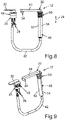
- eine schematische Seitenansicht der Wasserarmatur; und
- Fig. 9
- eine schematische Perspektivansicht der Wasserarmatur.
- In den Fig. sind gleiche oder funktionsgleiche Elemente mit gleichen Bezugszeichen versehen
-
Fig. 1 und 2 zeigen in einer jeweiligen schematischen Perspektivansicht eine im Ganzen mit 10 bezeichnete Anordnung einer Wasserarmatur 12 an einem Einrichtungsgegenstand 14 für eine Vorrichtung wie beispielsweise einen Wohnwagen, ein Caravan, ein Motorcaravan oder ein Boot. Bei der Anordnung 10 ist die Wasserarmatur 12 an dem Einrichtungsgegenstand 14 gehalten. Der Einrichtungsgegenstand 14 umfasst eine Arbeitsplatte 16, welche eine Oberfläche 18 aufweist. Außerdem umfasst der Einrichtungsgegenstand 14 ein beispielsweise als Spülbecken fungierendes Becken 20, welches beispielsweise zum Auffangen beziehungsweise Aufnehmen und Abführen von Wasser genutzt wird. Das Wasser, welches mittels des Beckens 20 aufgefangen und abgeführt werden kann, kann beispielsweise aus der Wasserarmatur 12 ausströmen, wie im Folgenden noch näher erläutert wird. Dabei ist ein Boden 22 des Beckens 20, insbesondere in Einbaulage der Wasserarmatur 12 und des Einrichtungsgegenstands 14, in vertikaler Richtung nach unten hin gegenüber der Oberfläche 18 zurückversetzt, wobei die vertikale Richtung inFig. 1 durch einen Doppelpfeil 24 veranschaulicht ist. - In Zusammenschau mit
Fig. 8 und 9 ist erkennbar, dass die Wasserarmatur 12 einen auch als Mischbatterie bezeichneten Mischer 26 aufweist, welcher, insbesondere über Wasseranschlüsse 28, mit Warmwasser und Kaltwasser versorgbar ist. Das Warmwasser und das Kaltwasser können beispielsweise über die Wasseranschlüsse 28 in den Mischer 26 und insbesondere in einen in den Fig. nicht erkennbaren Mischbereich des Mischers 26 einströmen, sodass das Warmwasser und das Kaltwasser in dem Mischbereich und somit mittels des Mischers 26 gemischt werden beziehungsweise gemischt werden können. Der Mischer 26 weist dabei ein Bedienelement 30 auf, mittels welchem beispielsweise ein Verhältnis des Kaltwassers zu dem Warmwasser einstellbar ist. Mit anderen Worten wird der Mischer 26 beispielsweise genutzt, um ein das Kaltwasser und das Warmwasser umfassendes Gemisch zu bilden. Mittels des Bedienelements 30 können dabei jeweilige Anteile des Warmwassers und des Kaltwassers an dem Gemisch eingestellt werden. - Die Wasserarmatur 12 umfasst ferner ein im Ganzen mit 32 bezeichnetes Wasserauslaufrohr, welches von dem Mischer 26 mit dem Kaltwasser und dem Warmwasser beziehungsweise mit dem Gemisch versorgbar ist. Das Wasserauslaufrohr 32 umfasst dabei wenigstens eine auch Austrittsöffnung bezeichnete Ausströmöffnung 34, über welche das Warmwasser beziehungsweise das Kaltwasser aus dem Wasserauslaufrohr 32 und somit aus der Wasserarmatur 12 insgesamt ausströmen und beispielsweise in das Becken 20 einströmen kann.
- Um nun einen besonders kompakten Aufbau realisieren zu können, ist das Wasserauslaufrohr 32 bezogen auf seine in den Fig. gezeigte Einbaulage in vertikaler Richtung höhenverstellbar, das heißt relativ zu dem Einrichtungsgegenstand 14 translatorisch bewegbar. Somit kann das Wasserauslaufrohr 32 in vertikaler Richtung relativ zu dem Einrichtungsgegenstand 14 zwischen wenigstens einer in
Fig. 2 gezeigten Gebrauchsstellung und wenigstens einer inFig. 3 gezeigten Verstaustellung verschoben werden. Dabei schließt sich an das Becken 20 eine mit dem Becken 20 verbundene Ausnehmung 36 an, in welcher das Wasserauslaufrohr 32 in der Verstaustellung zumindest teilweise aufgenommen ist. - Besonders gut aus
Fig. 1 und 2 ist erkennbar, dass das Wasserauslaufrohr 32 ein erstes Rohrteil 38 und ein zweites Rohrteil 40 aufweist. Bezogen auf die Einbaulage des Wasserauslaufrohrs 32 erstreckt sich das Rohrteil 38 zumindest im Wesentlichen in vertikaler Richtung, während sich das Rohrteil 40 schräg oder vorliegend senkrecht und somit in horizontaler Richtung erstreckt. Die Rohrteile 38 und 34 weisen somit jeweilige Längserstreckungsrichtungen auf, wobei die Längserstreckungsrichtung des Rohrteils 38 in vertikale Richtung und die Längserstreckungsrichtung des Rohrteils 40 in horizontaler Richtung verläuft. Dabei sind die Rohrteile 38 und 40 drehfest miteinander verbunden, wobei die Rohrteile 38 und 40 einstückig miteinander ausgebildet sein können. Die Wasserarmatur 12 nimmt dabei ihre Einbaulage in vollständig hergestelltem Zustand der Wasserarmatur 12 und der genannten Vorrichtung ein, wobei im vollständig hergestellten Zustand der Vorrichtung die Wasserarmatur 12 und der Einrichtungsgegenstand 14 an, insbesondere in, der Vorrichtung montiert sind, und wobei die Wasserarmatur 12 am Einrichtungsgegenstand 14 gehalten ist. Ferner nimmt die Wasserarmatur 12 beispielsweise ihre Einbaulage dann ein, wenn die Vorrichtung auf einer zumindest im Wesentlichen horizontalen Fläche steht. - Um einen besonders großen Weg zu realisieren, um welchen das Wasserauslaufrohr 32 in vertikaler Richtung höhenverstellt und somit angehoben und abgesenkt werden kann, ist das Wasserauslaufrohr 32 bezogen auf seine Einbaulage in vertikaler Richtung relativ zu dem Mischer 26 bewegbar und dadurch höhenverstellbar. Dabei ist das Wasserauslaufrohr 32, insbesondere wenigstens ein von dem Warmwasser und von dem Kaltwasser durchströmbarer Wasserkanal des Wasserauslaufrohrs 32, über einen flexiblen Schlauch 42 (
Fig. 8 und 9 ) fluidisch mit dem Mischer 26, insbesondere mit dem Mischbereich, verbunden, sodass das Wasserauslaufrohr 32 über den flexiblen Schlauch 42 mit dem von dem Mischer 26 bereitgestellten Warmwasser und Kaltwasser versorgbar ist beziehungsweise versorgt wird. Mittels des Bedienelements 30 kann dabei insbesondere eine Menge des Wassers eingestellt werden, die von dem Mischer 26 bereitgestellt und über den flexiblen Schlauch 42 zu dem Wasserauslaufrohr 32 geleitet wird und über die Ausströmöffnung 34 aus dem Wasserauslaufrohr 32 ausströmt. - Der flexible Schlauch 42 ist einenends mechanisch mit dem Mischer 26 und anderenends mechanisch mit dem Wasserauslaufrohr 32 verbunden, sodass sich beispielsweise zumindest ein Teil des flexiblen Schlauchs 42 mit dem Wasserauslaufrohr 32 mitbewegt, wenn das Wasserauslaufrohr 32 in vertikaler Richtung relativ zu dem Einrichtungsgegenstand 14 und relativ zu dem Mischer 26 in vertikaler Richtung bewegt wird.
- Aus
Fig. 1 bis 3 ist erkennbar, dass die inFig. 2 gezeigte Gebrauchsstellung des Wasserauslaufrohrs 32 mit einer Absenkschwenkstellung korrespondiert, da das Wasserauslaufrohr 32 dann, wenn es sich in der Absenkschwenkstellung befindet, in vertikaler Richtung relativ zu dem Einrichtungsgegenstand 14 und relativ zu dem Mischer 26 abgesenkt und dadurch in die inFig. 3 gezeigte Verstaustellung translatorisch bewegt werden kann. - Wird beispielsweise das Wasserauslaufrohr 32 ausgehend von der Absenkschwenkstellung, welche in
Fig. 2 gezeigt ist, um eine in vertikaler Richtung verlaufende Drehachse relativ zu dem Einrichtungsgegenstand 14 und relativ zu dem Mischer 26 verschwenkt, so kommt das Wasserauslaufrohr 32 beispielsweise in eine inFig. 2 gezeigte, von der Absenkschwenkstellung unterschiedliche Gebrauchsschwenkstellung. Insbesondere kann das Wasserauslaufrohr 32 zwischen der Absenkschwenkstellung und einer Vielzahl von von der Absenkschwenkstellung unterschiedlichen Gebrauchsschwenkstellungen um die genannte Drehachse relativ zu dem Einrichtungsgegenstand 14 und insbesondere relativ zu dem Mischer 26 verschwenkt werden. Das Wasserauslaufrohr 32 kann jedoch vorzugsweise dann und nur dann abgesenkt und somit in die Gebrauchsstellung bewegt werden, wenn sich das Wasserauslaufrohr 32 in der Absenkschwenkstellung befindet. Ein Absenken des Wasserauslaufrohrs 32 aus der jeweiligen, von der Absenkschwenkstellung unterschiedlichen Gebrauchsschwenkstellung ist nicht möglich und wird beispielsweise mittels einer an dem Wasserauslaufrohr 32 vorgesehenen, in den Fig. nicht erkennbaren ersten Führungseinrichtung und einer ausFig. 6 und 7 erkennbaren zweiten Führungseinrichtung 44 verhindert. - Ein erstes Rohrteil 38 wird auch als senkrechter Bereich bezeichnet, wobei ein zweites Rohrteil 40 auch als waagerechter Bereich bezeichnet wird. Aus
Fig. 6 bis 9 ist besonders gut erkennbar, dass das Wasserauslaufrohr 32, insbesondere das Rohrteil 38, bei der Anordnung 10 zumindest teilweise in einem als Führungsrohr fungierenden äußeren Rohrsegment 46 angeordnet ist. Durch Absenken des Wasserauslaufrohrs 32 taucht das Rohrteil 38 in das äußere Rohrsegment 46 ein. Wird das Wasserauslaufrohr 32 angehoben, so wird das Rohrteil 38 aus dem äußeren Rohrsegment 46 herausgezogen. Somit ist das Wasserauslaufrohr 32 in vertikaler Richtung relativ zu dem als Führungsrohr fungierenden äußeren Rohrsegment 46 höhenverstellbar. Das als Führungsrohrsegment fungierende Rohrsegment 46 ist beispielsweise in dem auch als Spüle bezeichneten Becken 20 selbst oder auch in der auch als Küchenarbeitsplatte bezeichneten Arbeitsplatte 16 so eingebaut, dass sich das Rohrsegment 46 zumindest überwiegend in vertikaler Richtung unterhalb des Beckens 20 beziehungsweise der Arbeitsplatte 16 erstreckt. - Bei dem in den Figuren veranschaulichten Ausführungsbeispiel weist der Mischer 26 ein als Gewinde, insbesondere als Außengewinde, ausgebildetes erstes Befestigungselement 48 auf, mittels welchem der Mischer 26 mit dem Einrichtungsgegenstand 14 verbunden beziehungsweise verbindbar ist. Des Weiteren weist das Rohrsegment 46 ein vorliegend als Gewinde, insbesondere als Außengewinde, ausgebildetes zweites Befestigungselement 50 auf, mittels welchem das Rohrsegment 46 mit dem Einrichtungsgegenstand 14 verbunden beziehungsweise verbindbar ist.
- Besonders gut aus
Fig. 8 und 9 ist erkennbar, dass das Rohrsegment 46 halbschalig ausgeführt ist und somit zwei auch als Rohrhalbschalen oder Schalenelemente bezeichnete Halbschalen 52 und 54 umfasst, von denen inFig. 6 und 7 die Halbschale 52 gezeigt ist. Das Rohrsegment 46 wird beispielsweise derart gebildet, dass die Halbschalen 52 und 54 zusammengebaut beziehungsweise zusammengesetzt werden. Die an dem Rohrsegment vorgesehen Führungseinrichtung 44 umfasst wenigstens beispielsweise als Führungsnut ausgebildete erste Führungsbahn 56 und eine beispielsweise als Führungsnut ausgebildete zweite Führungsbahn 58, welche mit der ersten Führungsbahn 56 verbunden ist. Die in den Fig. nicht erkennbare und beispielsweise an dem Wasserauslaufrohr 32, insbesondere an dem ersten Rohrteil 38, vorgesehene Führungseinrichtung umfasst beispielsweise wenigstens ein Führungselement, welches beispielsweise in der Verstaustellung in die erste Führungsbahn 56 eingreift. Somit wirken die Führungseinrichtungen formschlüssig zusammen. - Während die erste Führungsbahn 56, insbesondere geradlinig, in vertikaler Richtung verläuft, erstreckt sich die zweite Führungsbahn 58 in Umfangsrichtung des Rohrsegments 46 beziehungsweise des Wasserauslaufrohrs 32, insbesondere des ersten Rohrteils 38 und ist in einem Winkel zu der ersten Führungsbahn 56 angeordnet. Somit fungiert die erste Führungsbahn 56 als vertikale beziehungsweise senkrechte Absenk- und Anhebeführung, wobei die zweite Führungsbahn 58 als waagerecht beziehungsweise horizontale Dreh- beziehungsweise Schwenkführung fungiert.
- Der als flexible Zuleitung fungierende Schlauch 42 ist beispielsweise drehfest beziehungsweise verdrehsicher mit dem Wasserauslaufrohr 32, insbesondere mit dem Rohrteil 38, verbunden, sodass sich der Schlauch 42 beispielsweise in vertikaler Richtung nach unten hin an das Wasserauslaufrohr 32, insbesondere an das Rohrteil 38, anschließt. Somit bildet beispielsweise der Schlauch 42 einen unteren Abschluss des Rohrteils 38, welcher ein senkrechter Auslaufbereich des auch einfacher als Auslauf bezeichneten Wasserauslaufrohrs 32 bildet. Das genannte, beispielsweise an dem Wasserauslaufrohr 32, insbesondere an dem Rohrteil 38, vorgesehene Führungselement ist beispielsweise an einem unteren Ende des Rohrteils 38 beziehungsweise in einer unteren Hälfte, insbesondere in einem unteren Drittel, des Rohrteils 38 angeordnet.
- Wird beispielsweise das Wasserauslaufrohr 32 ausgehend von der Verstaustellung angehoben und dadurch von dem Becken 20 wegbewegt, so wird dadurch das Führungselement entlang der Führungsbahn 56 bewegt. Dadurch kommt das Wasserauslaufrohr 32 auf seinem Weg von der Verstaustellung in der Gebrauchsstellung (Absenkschwenkstellung) in mehrere, zwischen der Verstaustellung und der Gebrauchsstellung angeordneten Zwischenstellungen. In den Zwischenstellungen und in der Verstaustellung greift das Führungselement in die Führungsbahn 56 ein und wirkt derart mit der Führungsbahn 56 zusammen, dass die Führungsbahn 56 und das Führungselement in den Zwischenstellungen und in der Verstaustellung eine Drehung des Wasserauslaufrohrs 32 um die Drehachse relativ zu dem Rohrsegment 46 und somit relativ zu dem Einrichtungsgegenstand 14, mit welchem beispielsweise das Rohrsegment 46 drehfest verbunden ist, verhindern. Dies bedeutet, dass das Wasserauslaufrohr 32 in der Verstaustellung und in den Zwischenstellungen nicht um die Drehachse relativ zu dem Einrichtungsgegenstand 14 gedreht werden kann.
- Durch Bewegen des Wasserauslaufrohrs 32 in die Gebrauchsstellung kommt beispielsweise das Führungselement in die Führungsbahn 58 beziehungsweise in Überdeckung mit der Führungsbahn 58, sodass dann das Wasserauslaufrohr 32 ausgehend von der Gebrauchsstellung um die Drehachse relativ zu dem Rohrsegment 46 und somit relativ zu dem Einrichtungsgegenstand 14 in die jeweilige Gebrauchsschwenkstellung geschwenkt werden kann. Ein solches Verschwenken des Wasserauslaufrohrs 32 aus der Absenkschwenkstellung in die jeweilige Gebrauchsschwenkstellung lassen das Führungselement und die Führungsbahn 58 zu, da das Führungselement ausgehend von der Gebrauchsstellung (Absenkschwenkstellung) in die und insbesondere entlang der Führungsbahn 58 bewegt werden kann. Somit kann das Wasserauslaufrohr 32 in seiner oberen, das heißt ausgezogenen Position in Form der Gebrauchsstellung über das Becken 20 geschwenkt werden.
- In der jeweiligen Gebrauchsschwenkstellung wird das Wasserauslaufrohr 32 mittels des Führungselements und mittels der Führungsbahn 58 gegen ein unerwünschtes Absenken gesichert, da in der jeweiligen Gebrauchsschwenkstellung das Führungselement in die Führungsbahn 58 eingreift. Mit andere Worten kann das Wasserauslaufrohr 32 aus der jeweiligen Gebrauchsschenkstellung nicht abgesenkt und somit nicht auf das Becken 20 zubewegt werden. Um das Wasserauslaufrohr 32 wieder in die Verstaustellung zu bewegen, wird das Wasserauslaufrohr 32 aus der jeweiligen Gebrauchsschwenkstellung in die auch als Absenkposition bezeichnete Absenkschwenkstellung geschwenkt. Dann kann das Wasserauslaufrohr 32 insbesondere durch leichten Druck in vertikaler Richtung von oben nach unten abgesenkt und dadurch in die Ausnehmung 36 beziehungsweise in die Spüle (Becken 20) bewegt werden.
- Um beispielsweise zu verhindern, dass sich das in der Absenkschwenkstellung befindende Wasserauslaufrohr 32 selbstständig beispielsweise aufgrund seines Eigengewichts absenkt und somit beispielsweise herabfällt, ist beispielsweise ein insbesondere als Dichtungselement ausgebildetes Abbremselement vorgesehen, welches beispielsweise zwischen dem Rohrteil 38 und dem Rohrsegment 46 angeordnet ist und dabei insbesondere einerseits an dem Rohrteil 38 und andererseits an dem Rohrsegment 46 abgestützt ist. Das Abbremselement ist beispielsweise ein Elastomer- beziehungsweise Gummielement wie etwa ein O-Ring, ein Quad-, Axial-, Flach- oder Lippendichtring. Das Abbremselement übt insbesondere durch Reibung eine dem Absenken des Wasserauslaufrohrs 32 entgegenstehende Kraft auf das Wasserauslaufrohr 32 aus, wodurch beispielsweise das insbesondere selbstständige Absenken des Wasserauslaufrohrs 32 abgebremst beziehungsweise verhindert wird. Zudem kann das Abbremselement für einen Bereich unterhalb des Beckens 20 beziehungsweise der Arbeitsplatte 16 als Abdichtung gegen eindringendes Wasser fungieren.
- Im Vergleich zu Absenkmechanismen mit Feder- und/oder Dämpferelementen und/oder motorischen, insbesondere elektromotorischen, Antrieben, können bei der Anordnung 10 deutliche Kosten- und Gewichtseinsparungen erzielt werden. Zudem ergibt sich dadurch ein erheblich geringerer Bauraum unterhalb des Beckens 20 beziehungsweise der Arbeitsplatte 16, sodass ein besonders gewichtsgünstiger, kostengünstiger und kompakter Aufbau dargestellt werden kann.
- Wie aus
Fig. 3 erkennbar ist, ist das Rohrteil 40 in der Verstaustellung vollständig in der Ausnehmung 36 aufgenommen und gegenüber der Oberfläche 18 zurückversetzt. Dadurch ist es beispielsweise möglich, das Becken 20, die Ausnehmung 36 und das in der Ausnehmung 36 aufgenommene Rohrteil 40 mittels eines ausFig. 4 erkennbaren und insbesondere eigensteifen Abdeckelements 60 abzudecken, welches beispielsweise als Abdeckplatte ausgebildet ist. Das Abdeckelement 60 weist beispielsweise eine weitere Oberfläche 62 auf, welche dann, wenn das Becken 20, die Ausnehmung 36 und das Rohrteil 40 mittels des Abdeckelements 60 abgedeckt beziehungsweise überdeckt sind, bündig mit der sich an die Oberfläche 62 anschließenden Oberfläche 18 der Arbeitsplatte 16 angeordnet ist. Dadurch bilden die bündig miteinander angeordneten Oberflächen 18 und 62 eine besonders große zur Verfügung stehende Arbeitsfläche 64 insgesamt.
Claims (10)
- Anordnung (10) mit Wasserarmatur (12) und einem Einrichtungsgegenstand (14), wobei die Wasserarmatur (12) an dem Einrichtungsgegenstand (14) gehalten ist und einen mit Warmwasser und Kaltwasser versorgbaren Mischer (26) zum Mischen des Warmwassers mit dem Kaltwasser und ein von dem Mischer (26) mit dem Warmwasser und dem Kaltwasser versorgbares Wasserauslaufrohr (32) aufweist, wobei das Wasserauslaufrohr (32) in vertikaler Richtung relativ zu dem Einrichtungsgegenstand (14) höhenverstellbar ist, wobei das Wasserauslaufrohr (32) ein in Einbaulage des Wasserauslaufrohrs (32) in vertikaler Richtung (24) verlaufendes erstes Rohrteil (38) und ein schräg oder senkrecht zum ersten Rohrteil (38) verlaufendes zweites Rohrteil (40) aufweist, wobei das erste Rohrteil (38) wenigstens eine Führungseinrichtung aufweist, mittels welcher das Wasserauslaufrohr (32) beim Höhenverstellen zu führen ist, und wobei das Wasserauslaufrohr (32) bezogen auf seine Einbaulage in vertikaler Richtung (24) zwischen wenigstens einer Verstaustellung und wenigstens einer Gebrauchsstellung verschiebbar ist, in welcher das Wasserauslaufrohr (32) gegenüber der Verstaustellung in vertikaler Richtung höher angeordnet ist, wobei die Führungseinrichtung in der Gebrauchsstellung eine Drehung des Wasserauslaufrohrs (32) um eine in vertikaler Richtung verlaufende Drehachse zulässt,
dadurch gekennzeichnet, dass
die Führungseinrichtung in der Verstaustellung eine Drehung des Wasserauslaufrohrs (32) um die Drehachse verhindert, wobei der Einrichtungsgegenstand (14) eine Arbeitsplatte (16), welche eine Oberfläche (18) aufweist, und ein Becken (20) zum Auffangen und Abführen von Wasser umfasst, wobei sich an das Becken (20) eine mit dem Becken (20) verbundene Ausnehmung (36) anschließt, und wobei das zweite Rohrteil (40) in der Verstaustellung vollständig in der Ausnehmung (36) aufgenommen und gegenüber der Oberfläche (18) zurückversetzt ist. - Anordnung nach Anspruch 1,
dadurch gekennzeichnet, dass
das Wasserauslaufrohr (32) bezogen auf seine Einbaulage in vertikaler Richtung (24) relativ zu dem Mischer (26) translatorisch bewegbar und dadurch höhenverstellbar ist. - Anordnung nach Anspruch 1 oder 2,
dadurch gekennzeichnet, dass
das Wasserauslaufrohr (32) mit dem Mischer (26) über einen flexiblen Schlauch (42) fluidisch verbunden ist, über welchen das Wasserauslaufrohr (32) mit dem von dem Mischer (26) bereitgestellten Warmwasser und Kaltwasser versorgbar ist. - Anordnung nach den Ansprüchen 2 und 3,
dadurch gekennzeichnet, dass
sich bei in vertikaler Richtung (24) verlaufenden Relativbewegungen zwischen dem Wasserauslaufrohr (32) und dem Mischer (26) zumindest ein Teil des Schlauches (42) mit dem Wasserauslaufrohr (42) relativ zu dem Mischer (26) mitbewegt. - Anordnung nach einem der vorhergehenden Ansprüche,
dadurch gekennzeichnet, dass
die Führungseinrichtung eine erste und zweite Führungsbahn (56, 58) umfasst, wobei die zweite Führungsbahn (58) mit der ersten Führungsbahn (56) verbunden ist und die erste Führungsbahn in oder an dem ersten Rohrteil (38) ausgebildet ist, wobei die zweite Führungsbahn (58) in einem Winkel zu der ersten Führungsbahn (56) angeordnet ist. - Anordnung nach Anspruch 5,
dadurch gekennzeichnet, dass
die zweite Führungsbahn (58) in Umfangsrichtung des ersten Rohrteils (38) ausgebildet ist. - Anordnung nach einem der vorhergehenden Ansprüche,
gekennzeichnet durch
wenigstens ein aus einem Kunststoff gebildetes Abbremselement, welches eine der Höhenverstellung entgegenwirkende Kraft auf das Wasserauslaufrohr (32) ausübt. - Anordnung nach Anspruch 7,
dadurch gekennzeichnet, dass
das Abbremselement als Dichtungselement ausgebildet ist, mittels welchem das Wasserauslaufrohr (32) gegen wenigstens ein weiteres Bauteil der Wasserarmatur (12) abgedichtet ist. - Anhänger, umfassend wenigstens eine Anordnung (10) nach einem der vorhergehenden Ansprüche.
- Fahrzeug, umfassend wenigstens eine Anordnung (10) nach einem der Ansprüche 1 bis 8.
Applications Claiming Priority (1)
| Application Number | Priority Date | Filing Date | Title |
|---|---|---|---|
| DE202017105096.3U DE202017105096U1 (de) | 2017-08-24 | 2017-08-24 | Wasserarmatur, insbesondere für einen Wohnwagen, Caravan, Motorcaravan oder ein Boot, Anordnung einer solchen Wasserarmatur an einem Einrichtungsgegenstand, sowie Anhänger und Fahrzeug |
Publications (2)
| Publication Number | Publication Date |
|---|---|
| EP3450639A1 EP3450639A1 (de) | 2019-03-06 |
| EP3450639B1 true EP3450639B1 (de) | 2022-06-01 |
Family
ID=63350460
Family Applications (1)
| Application Number | Title | Priority Date | Filing Date |
|---|---|---|---|
| EP18190050.7A Active EP3450639B1 (de) | 2017-08-24 | 2018-08-21 | Versenkbare wasserarmatur |
Country Status (2)
| Country | Link |
|---|---|
| EP (1) | EP3450639B1 (de) |
| DE (1) | DE202017105096U1 (de) |
Families Citing this family (2)
| Publication number | Priority date | Publication date | Assignee | Title |
|---|---|---|---|---|
| CN111456160B (zh) * | 2020-05-21 | 2021-04-06 | 合肥迈亚家具有限公司 | 用于实现盥洗台洗漱及装饰功能切换的方法 |
| CN111543876B (zh) * | 2020-05-21 | 2021-11-23 | 合肥迈亚家具有限公司 | 洗漱装饰一体式盥洗台 |
Family Cites Families (10)
| Publication number | Priority date | Publication date | Assignee | Title |
|---|---|---|---|---|
| IT1188150B (it) * | 1986-05-14 | 1987-12-30 | Gevipi Ag | Rubinetto con becco di erogazione ad orientabilita multipla |
| DE4440904A1 (de) * | 1994-11-17 | 1996-05-23 | Blanco Gmbh & Co Kg | Mischbatterie-Wasserauslaufeinrichtung |
| DE4444657A1 (de) * | 1994-11-17 | 1996-05-30 | Blanco Gmbh & Co Kg | Einbauspüle |
| AT407167B (de) * | 1998-10-15 | 2001-01-25 | Ideal Standard | Sanitäre armatur |
| DE20006841U1 (de) * | 2000-04-14 | 2001-06-07 | CKW Gesellschaft für Kunststoffverarbeitung mbH, 99887 Catterfeld | Spülenarmatur für den Haushalt, Caravane oder Boote |
| ITMI20031170A1 (it) * | 2003-06-10 | 2004-12-11 | Gallazzini S P A | Rubinetto miscelatore monocomando sottofinestra con canna abbattibile. |
| DE202004005561U1 (de) * | 2004-04-07 | 2004-07-01 | Reich Kg, Regel- Und Sicherheitstechnik | Wasserauslaufarmatur |
| US8230882B2 (en) * | 2007-02-21 | 2012-07-31 | Neoperl Gmbh | Telescoping water outlet |
| DE202009004785U1 (de) * | 2009-05-06 | 2010-09-23 | Hettich Holding Gmbh & Co. Ohg | Vorrichtung zur Ausgabe von Wasser |
| EP2378011B8 (de) * | 2010-04-13 | 2016-09-28 | Franke Water Systems AG | Höhenverstellbare Sanitärarmatur mit einem magnetischen Haltesystem |
-
2017
- 2017-08-24 DE DE202017105096.3U patent/DE202017105096U1/de not_active Expired - Lifetime
-
2018
- 2018-08-21 EP EP18190050.7A patent/EP3450639B1/de active Active
Also Published As
| Publication number | Publication date |
|---|---|
| EP3450639A1 (de) | 2019-03-06 |
| DE202017105096U1 (de) | 2018-08-30 |
Similar Documents
| Publication | Publication Date | Title |
|---|---|---|
| EP2236359B1 (de) | Sanitärmodul und Sanitärsystem, insbesondere eines Fahrzeugs | |
| EP2110482B1 (de) | Sanitäreinrichtung aufweisend eine Sanitärarmatur mit einem aus- und einfahrbaren Auslaufrohr | |
| EP3450639A1 (de) | Versenkbare wasserarmatur | |
| DE102015114327B3 (de) | Wasserarmatur, insbesondere für einen Wohnwagen, Caravan, Motorcaravan oder ein Boot | |
| DE3428545C2 (de) | ||
| EP1707692B1 (de) | Sanitärarmatur mit teleskopierbarem Auslaufsystem | |
| EP1592087A1 (de) | Versorgungsanschluss für Wohnmobile oder Wohnwagen | |
| EP3447199B1 (de) | Wegklappbare wasserarmatur, insbesondere für einen wohnwagen und dgl. | |
| DE102016119472A1 (de) | Gerätehalterung | |
| EP1435480B1 (de) | Sanitärarmatur | |
| EP0712964B2 (de) | Mischbatterie-Wasserauslaufeinrichtung | |
| DE4420436A1 (de) | Sanitärarmatur, insbesondere Küchenmischbatterie | |
| EP3647502B1 (de) | Spülbeckenanordnung mit einem spülbecken und einer spülbeckenarmatur | |
| DE3204053A1 (de) | Duschkabine | |
| DE102011112227B4 (de) | Absperrvorrichtung für die Wasserzufuhr zu einem Hydranten | |
| EP1717380A1 (de) | Anschlussvorrichtung zum Anschliessen eines Sanitärartikels | |
| EP3045593A1 (de) | Küchenarmatur mit schwenkbarem mundstück | |
| EP1842972A1 (de) | Sanitärarmatur mit versenkbarem Auslauf | |
| DE102006022162B3 (de) | Unterflurhydrant | |
| DE102004041796B4 (de) | Sanitärarmatur | |
| EP1637363B1 (de) | Manueller Antrieb für eine Anhängerkupplung | |
| DE202004013395U1 (de) | Wasserauslaufarmatur | |
| EP4551081A1 (de) | Wc-sitz-ring | |
| DE10312863A1 (de) | Brausenanordnung | |
| EP3138966B1 (de) | Wasserarmatur, insbesondere für einen wohnwagen, caravan, motorcaravan oder ein boot |
Legal Events
| Date | Code | Title | Description |
|---|---|---|---|
| PUAI | Public reference made under article 153(3) epc to a published international application that has entered the european phase |
Free format text: ORIGINAL CODE: 0009012 |
|
| STAA | Information on the status of an ep patent application or granted ep patent |
Free format text: STATUS: THE APPLICATION HAS BEEN PUBLISHED |
|
| AK | Designated contracting states |
Kind code of ref document: A1 Designated state(s): AL AT BE BG CH CY CZ DE DK EE ES FI FR GB GR HR HU IE IS IT LI LT LU LV MC MK MT NL NO PL PT RO RS SE SI SK SM TR |
|
| AX | Request for extension of the european patent |
Extension state: BA ME |
|
| STAA | Information on the status of an ep patent application or granted ep patent |
Free format text: STATUS: REQUEST FOR EXAMINATION WAS MADE |
|
| 17P | Request for examination filed |
Effective date: 20190906 |
|
| RBV | Designated contracting states (corrected) |
Designated state(s): AL AT BE BG CH CY CZ DE DK EE ES FI FR GB GR HR HU IE IS IT LI LT LU LV MC MK MT NL NO PL PT RO RS SE SI SK SM TR |
|
| STAA | Information on the status of an ep patent application or granted ep patent |
Free format text: STATUS: EXAMINATION IS IN PROGRESS |
|
| 17Q | First examination report despatched |
Effective date: 20200225 |
|
| GRAP | Despatch of communication of intention to grant a patent |
Free format text: ORIGINAL CODE: EPIDOSNIGR1 |
|
| STAA | Information on the status of an ep patent application or granted ep patent |
Free format text: STATUS: GRANT OF PATENT IS INTENDED |
|
| INTG | Intention to grant announced |
Effective date: 20220107 |
|
| GRAS | Grant fee paid |
Free format text: ORIGINAL CODE: EPIDOSNIGR3 |
|
| GRAA | (expected) grant |
Free format text: ORIGINAL CODE: 0009210 |
|
| STAA | Information on the status of an ep patent application or granted ep patent |
Free format text: STATUS: THE PATENT HAS BEEN GRANTED |
|
| AK | Designated contracting states |
Kind code of ref document: B1 Designated state(s): AL AT BE BG CH CY CZ DE DK EE ES FI FR GB GR HR HU IE IS IT LI LT LU LV MC MK MT NL NO PL PT RO RS SE SI SK SM TR |
|
| REG | Reference to a national code |
Ref country code: GB Ref legal event code: FG4D Free format text: NOT ENGLISH |
|
| REG | Reference to a national code |
Ref country code: AT Ref legal event code: REF Ref document number: 1495451 Country of ref document: AT Kind code of ref document: T Effective date: 20220615 Ref country code: CH Ref legal event code: EP Ref country code: DE Ref legal event code: R096 Ref document number: 502018009793 Country of ref document: DE |
|
| REG | Reference to a national code |
Ref country code: IE Ref legal event code: FG4D Free format text: LANGUAGE OF EP DOCUMENT: GERMAN |
|
| REG | Reference to a national code |
Ref country code: NL Ref legal event code: FP |
|
| REG | Reference to a national code |
Ref country code: SE Ref legal event code: TRGR |
|
| REG | Reference to a national code |
Ref country code: LT Ref legal event code: MG9D |
|
| PG25 | Lapsed in a contracting state [announced via postgrant information from national office to epo] |
Ref country code: NO Free format text: LAPSE BECAUSE OF FAILURE TO SUBMIT A TRANSLATION OF THE DESCRIPTION OR TO PAY THE FEE WITHIN THE PRESCRIBED TIME-LIMIT Effective date: 20220901 Ref country code: LT Free format text: LAPSE BECAUSE OF FAILURE TO SUBMIT A TRANSLATION OF THE DESCRIPTION OR TO PAY THE FEE WITHIN THE PRESCRIBED TIME-LIMIT Effective date: 20220601 Ref country code: HR Free format text: LAPSE BECAUSE OF FAILURE TO SUBMIT A TRANSLATION OF THE DESCRIPTION OR TO PAY THE FEE WITHIN THE PRESCRIBED TIME-LIMIT Effective date: 20220601 Ref country code: GR Free format text: LAPSE BECAUSE OF FAILURE TO SUBMIT A TRANSLATION OF THE DESCRIPTION OR TO PAY THE FEE WITHIN THE PRESCRIBED TIME-LIMIT Effective date: 20220902 Ref country code: FI Free format text: LAPSE BECAUSE OF FAILURE TO SUBMIT A TRANSLATION OF THE DESCRIPTION OR TO PAY THE FEE WITHIN THE PRESCRIBED TIME-LIMIT Effective date: 20220601 Ref country code: ES Free format text: LAPSE BECAUSE OF FAILURE TO SUBMIT A TRANSLATION OF THE DESCRIPTION OR TO PAY THE FEE WITHIN THE PRESCRIBED TIME-LIMIT Effective date: 20220601 Ref country code: BG Free format text: LAPSE BECAUSE OF FAILURE TO SUBMIT A TRANSLATION OF THE DESCRIPTION OR TO PAY THE FEE WITHIN THE PRESCRIBED TIME-LIMIT Effective date: 20220901 |
|
| PG25 | Lapsed in a contracting state [announced via postgrant information from national office to epo] |
Ref country code: RS Free format text: LAPSE BECAUSE OF FAILURE TO SUBMIT A TRANSLATION OF THE DESCRIPTION OR TO PAY THE FEE WITHIN THE PRESCRIBED TIME-LIMIT Effective date: 20220601 Ref country code: PL Free format text: LAPSE BECAUSE OF FAILURE TO SUBMIT A TRANSLATION OF THE DESCRIPTION OR TO PAY THE FEE WITHIN THE PRESCRIBED TIME-LIMIT Effective date: 20220601 Ref country code: LV Free format text: LAPSE BECAUSE OF FAILURE TO SUBMIT A TRANSLATION OF THE DESCRIPTION OR TO PAY THE FEE WITHIN THE PRESCRIBED TIME-LIMIT Effective date: 20220601 |
|
| PG25 | Lapsed in a contracting state [announced via postgrant information from national office to epo] |
Ref country code: SM Free format text: LAPSE BECAUSE OF FAILURE TO SUBMIT A TRANSLATION OF THE DESCRIPTION OR TO PAY THE FEE WITHIN THE PRESCRIBED TIME-LIMIT Effective date: 20220601 Ref country code: SK Free format text: LAPSE BECAUSE OF FAILURE TO SUBMIT A TRANSLATION OF THE DESCRIPTION OR TO PAY THE FEE WITHIN THE PRESCRIBED TIME-LIMIT Effective date: 20220601 Ref country code: RO Free format text: LAPSE BECAUSE OF FAILURE TO SUBMIT A TRANSLATION OF THE DESCRIPTION OR TO PAY THE FEE WITHIN THE PRESCRIBED TIME-LIMIT Effective date: 20220601 Ref country code: PT Free format text: LAPSE BECAUSE OF FAILURE TO SUBMIT A TRANSLATION OF THE DESCRIPTION OR TO PAY THE FEE WITHIN THE PRESCRIBED TIME-LIMIT Effective date: 20221003 Ref country code: EE Free format text: LAPSE BECAUSE OF FAILURE TO SUBMIT A TRANSLATION OF THE DESCRIPTION OR TO PAY THE FEE WITHIN THE PRESCRIBED TIME-LIMIT Effective date: 20220601 Ref country code: CZ Free format text: LAPSE BECAUSE OF FAILURE TO SUBMIT A TRANSLATION OF THE DESCRIPTION OR TO PAY THE FEE WITHIN THE PRESCRIBED TIME-LIMIT Effective date: 20220601 |
|
| PG25 | Lapsed in a contracting state [announced via postgrant information from national office to epo] |
Ref country code: IS Free format text: LAPSE BECAUSE OF FAILURE TO SUBMIT A TRANSLATION OF THE DESCRIPTION OR TO PAY THE FEE WITHIN THE PRESCRIBED TIME-LIMIT Effective date: 20221001 |
|
| REG | Reference to a national code |
Ref country code: DE Ref legal event code: R097 Ref document number: 502018009793 Country of ref document: DE |
|
| PG25 | Lapsed in a contracting state [announced via postgrant information from national office to epo] |
Ref country code: MC Free format text: LAPSE BECAUSE OF FAILURE TO SUBMIT A TRANSLATION OF THE DESCRIPTION OR TO PAY THE FEE WITHIN THE PRESCRIBED TIME-LIMIT Effective date: 20220601 Ref country code: AL Free format text: LAPSE BECAUSE OF FAILURE TO SUBMIT A TRANSLATION OF THE DESCRIPTION OR TO PAY THE FEE WITHIN THE PRESCRIBED TIME-LIMIT Effective date: 20220601 |
|
| REG | Reference to a national code |
Ref country code: CH Ref legal event code: PL |
|
| PLBE | No opposition filed within time limit |
Free format text: ORIGINAL CODE: 0009261 |
|
| STAA | Information on the status of an ep patent application or granted ep patent |
Free format text: STATUS: NO OPPOSITION FILED WITHIN TIME LIMIT |
|
| PG25 | Lapsed in a contracting state [announced via postgrant information from national office to epo] |
Ref country code: LU Free format text: LAPSE BECAUSE OF NON-PAYMENT OF DUE FEES Effective date: 20220821 Ref country code: LI Free format text: LAPSE BECAUSE OF NON-PAYMENT OF DUE FEES Effective date: 20220831 Ref country code: DK Free format text: LAPSE BECAUSE OF FAILURE TO SUBMIT A TRANSLATION OF THE DESCRIPTION OR TO PAY THE FEE WITHIN THE PRESCRIBED TIME-LIMIT Effective date: 20220601 Ref country code: CH Free format text: LAPSE BECAUSE OF NON-PAYMENT OF DUE FEES Effective date: 20220831 |
|
| REG | Reference to a national code |
Ref country code: BE Ref legal event code: MM Effective date: 20220831 |
|
| 26N | No opposition filed |
Effective date: 20230302 |
|
| PG25 | Lapsed in a contracting state [announced via postgrant information from national office to epo] |
Ref country code: SI Free format text: LAPSE BECAUSE OF FAILURE TO SUBMIT A TRANSLATION OF THE DESCRIPTION OR TO PAY THE FEE WITHIN THE PRESCRIBED TIME-LIMIT Effective date: 20220601 |
|
| P01 | Opt-out of the competence of the unified patent court (upc) registered |
Effective date: 20230601 |
|
| PG25 | Lapsed in a contracting state [announced via postgrant information from national office to epo] |
Ref country code: IE Free format text: LAPSE BECAUSE OF NON-PAYMENT OF DUE FEES Effective date: 20220821 |
|
| PG25 | Lapsed in a contracting state [announced via postgrant information from national office to epo] |
Ref country code: BE Free format text: LAPSE BECAUSE OF NON-PAYMENT OF DUE FEES Effective date: 20220831 |
|
| PG25 | Lapsed in a contracting state [announced via postgrant information from national office to epo] |
Ref country code: HU Free format text: LAPSE BECAUSE OF FAILURE TO SUBMIT A TRANSLATION OF THE DESCRIPTION OR TO PAY THE FEE WITHIN THE PRESCRIBED TIME-LIMIT; INVALID AB INITIO Effective date: 20180821 |
|
| PG25 | Lapsed in a contracting state [announced via postgrant information from national office to epo] |
Ref country code: CY Free format text: LAPSE BECAUSE OF FAILURE TO SUBMIT A TRANSLATION OF THE DESCRIPTION OR TO PAY THE FEE WITHIN THE PRESCRIBED TIME-LIMIT Effective date: 20220601 |
|
| PG25 | Lapsed in a contracting state [announced via postgrant information from national office to epo] |
Ref country code: MK Free format text: LAPSE BECAUSE OF FAILURE TO SUBMIT A TRANSLATION OF THE DESCRIPTION OR TO PAY THE FEE WITHIN THE PRESCRIBED TIME-LIMIT Effective date: 20220601 |
|
| PG25 | Lapsed in a contracting state [announced via postgrant information from national office to epo] |
Ref country code: MT Free format text: LAPSE BECAUSE OF FAILURE TO SUBMIT A TRANSLATION OF THE DESCRIPTION OR TO PAY THE FEE WITHIN THE PRESCRIBED TIME-LIMIT Effective date: 20220601 |
|
| REG | Reference to a national code |
Ref country code: AT Ref legal event code: MM01 Ref document number: 1495451 Country of ref document: AT Kind code of ref document: T Effective date: 20230821 |
|
| PG25 | Lapsed in a contracting state [announced via postgrant information from national office to epo] |
Ref country code: AT Free format text: LAPSE BECAUSE OF NON-PAYMENT OF DUE FEES Effective date: 20230821 |
|
| PG25 | Lapsed in a contracting state [announced via postgrant information from national office to epo] |
Ref country code: AT Free format text: LAPSE BECAUSE OF NON-PAYMENT OF DUE FEES Effective date: 20230821 |
|
| PG25 | Lapsed in a contracting state [announced via postgrant information from national office to epo] |
Ref country code: BG Free format text: LAPSE BECAUSE OF FAILURE TO SUBMIT A TRANSLATION OF THE DESCRIPTION OR TO PAY THE FEE WITHIN THE PRESCRIBED TIME-LIMIT Effective date: 20220601 |
|
| PG25 | Lapsed in a contracting state [announced via postgrant information from national office to epo] |
Ref country code: BG Free format text: LAPSE BECAUSE OF FAILURE TO SUBMIT A TRANSLATION OF THE DESCRIPTION OR TO PAY THE FEE WITHIN THE PRESCRIBED TIME-LIMIT Effective date: 20220601 |
|
| PGFP | Annual fee paid to national office [announced via postgrant information from national office to epo] |
Ref country code: NL Payment date: 20250821 Year of fee payment: 8 |
|
| PGFP | Annual fee paid to national office [announced via postgrant information from national office to epo] |
Ref country code: DE Payment date: 20250825 Year of fee payment: 8 |
|
| PGFP | Annual fee paid to national office [announced via postgrant information from national office to epo] |
Ref country code: IT Payment date: 20250829 Year of fee payment: 8 |
|
| PGFP | Annual fee paid to national office [announced via postgrant information from national office to epo] |
Ref country code: GB Payment date: 20250822 Year of fee payment: 8 |
|
| PGFP | Annual fee paid to national office [announced via postgrant information from national office to epo] |
Ref country code: FR Payment date: 20250821 Year of fee payment: 8 |
|
| PGFP | Annual fee paid to national office [announced via postgrant information from national office to epo] |
Ref country code: SE Payment date: 20250821 Year of fee payment: 8 |
|
| PG25 | Lapsed in a contracting state [announced via postgrant information from national office to epo] |
Ref country code: TR Free format text: LAPSE BECAUSE OF FAILURE TO SUBMIT A TRANSLATION OF THE DESCRIPTION OR TO PAY THE FEE WITHIN THE PRESCRIBED TIME-LIMIT Effective date: 20220601 |
|
| PGFP | Annual fee paid to national office [announced via postgrant information from national office to epo] |
Ref country code: AT Payment date: 20260410 Year of fee payment: 5 |