EP3450341B1 - Faltschachtel mit lichtschutz - Google Patents
Faltschachtel mit lichtschutz Download PDFInfo
- Publication number
- EP3450341B1 EP3450341B1 EP18186943.9A EP18186943A EP3450341B1 EP 3450341 B1 EP3450341 B1 EP 3450341B1 EP 18186943 A EP18186943 A EP 18186943A EP 3450341 B1 EP3450341 B1 EP 3450341B1
- Authority
- EP
- European Patent Office
- Prior art keywords
- panel
- panels
- folding box
- light
- tear line
- Prior art date
- Legal status (The legal status is an assumption and is not a legal conclusion. Google has not performed a legal analysis and makes no representation as to the accuracy of the status listed.)
- Active
Links
- 230000000295 complement effect Effects 0.000 claims description 4
- 238000004026 adhesive bonding Methods 0.000 description 2
- 238000004519 manufacturing process Methods 0.000 description 2
- 238000003780 insertion Methods 0.000 description 1
- 230000037431 insertion Effects 0.000 description 1
- 239000000463 material Substances 0.000 description 1
Images
Classifications
-
- B—PERFORMING OPERATIONS; TRANSPORTING
- B65—CONVEYING; PACKING; STORING; HANDLING THIN OR FILAMENTARY MATERIAL
- B65D—CONTAINERS FOR STORAGE OR TRANSPORT OF ARTICLES OR MATERIALS, e.g. BAGS, BARRELS, BOTTLES, BOXES, CANS, CARTONS, CRATES, DRUMS, JARS, TANKS, HOPPERS, FORWARDING CONTAINERS; ACCESSORIES, CLOSURES, OR FITTINGS THEREFOR; PACKAGING ELEMENTS; PACKAGES
- B65D5/00—Rigid or semi-rigid containers of polygonal cross-section, e.g. boxes, cartons or trays, formed by folding or erecting one or more blanks made of paper
- B65D5/42—Details of containers or of foldable or erectable container blanks
- B65D5/54—Lines of weakness to facilitate opening of container or dividing it into separate parts by cutting or tearing
- B65D5/5405—Lines of weakness to facilitate opening of container or dividing it into separate parts by cutting or tearing for opening containers formed by erecting a blank in tubular form
- B65D5/542—Lines of weakness to facilitate opening of container or dividing it into separate parts by cutting or tearing for opening containers formed by erecting a blank in tubular form the lines of weakness being provided in the container body
- B65D5/5425—Lines of weakness to facilitate opening of container or dividing it into separate parts by cutting or tearing for opening containers formed by erecting a blank in tubular form the lines of weakness being provided in the container body and defining after rupture a lid hinged to the upper edge of the container body
- B65D5/543—Lines of weakness to facilitate opening of container or dividing it into separate parts by cutting or tearing for opening containers formed by erecting a blank in tubular form the lines of weakness being provided in the container body and defining after rupture a lid hinged to the upper edge of the container body the container being provided with an internal frame or the like for maintaining the lid in the closed position by friction
-
- B—PERFORMING OPERATIONS; TRANSPORTING
- B65—CONVEYING; PACKING; STORING; HANDLING THIN OR FILAMENTARY MATERIAL
- B65D—CONTAINERS FOR STORAGE OR TRANSPORT OF ARTICLES OR MATERIALS, e.g. BAGS, BARRELS, BOTTLES, BOXES, CANS, CARTONS, CRATES, DRUMS, JARS, TANKS, HOPPERS, FORWARDING CONTAINERS; ACCESSORIES, CLOSURES, OR FITTINGS THEREFOR; PACKAGING ELEMENTS; PACKAGES
- B65D5/00—Rigid or semi-rigid containers of polygonal cross-section, e.g. boxes, cartons or trays, formed by folding or erecting one or more blanks made of paper
- B65D5/02—Rigid or semi-rigid containers of polygonal cross-section, e.g. boxes, cartons or trays, formed by folding or erecting one or more blanks made of paper by folding or erecting a single blank to form a tubular body with or without subsequent folding operations, or the addition of separate elements, to close the ends of the body
- B65D5/0281—Rigid or semi-rigid containers of polygonal cross-section, e.g. boxes, cartons or trays, formed by folding or erecting one or more blanks made of paper by folding or erecting a single blank to form a tubular body with or without subsequent folding operations, or the addition of separate elements, to close the ends of the body the tubular body presenting double or multiple walls
-
- B—PERFORMING OPERATIONS; TRANSPORTING
- B65—CONVEYING; PACKING; STORING; HANDLING THIN OR FILAMENTARY MATERIAL
- B65D—CONTAINERS FOR STORAGE OR TRANSPORT OF ARTICLES OR MATERIALS, e.g. BAGS, BARRELS, BOTTLES, BOXES, CANS, CARTONS, CRATES, DRUMS, JARS, TANKS, HOPPERS, FORWARDING CONTAINERS; ACCESSORIES, CLOSURES, OR FITTINGS THEREFOR; PACKAGING ELEMENTS; PACKAGES
- B65D5/00—Rigid or semi-rigid containers of polygonal cross-section, e.g. boxes, cartons or trays, formed by folding or erecting one or more blanks made of paper
- B65D5/42—Details of containers or of foldable or erectable container blanks
- B65D5/64—Lids
- B65D5/66—Hinged lids
- B65D5/6602—Hinged lids formed by folding one or more extensions hinged to the upper edge of a tubular container body
- B65D5/662—Hinged lids formed by folding one or more extensions hinged to the upper edge of a tubular container body the container being provided with an internal frame or the like for maintaining the lid in the closed position by friction
Definitions
- the present invention relates to a folding box made of a one-piece, in the basic state flat base body, which in a folded state defines an inner pocket for receiving removable, light-sensitive cloths, comprising at least five panels which are laterally separated from one another by longitudinal fold lines, the first, third and fifth panel have substantially the same width, and the second and fourth panels have substantially the same width, and wherein on the first to fourth panels upper and lower tabs are hinged to an upper and lower horizontal fold line so that the upper and lower Tabs can form upper or lower walls, a tear line leading from the first panel through the second panel to the third panel and bordering a central horizontal fold line in the fourth panel, in order to provide a tear-open hinged lid.
- Boxes for holding light-sensitive wipes are known in the prior art. However, these boxes normally allow unimpeded light to enter the contents through the opening provided for removing the wipes. In addition, a closed box can often inadvertently open partially or completely, for example due to mechanical tension in the area of a lid part, which also enables undesired incidence of light.
- the publication FR 2 818 958 A1 discloses a folding box, which consists of a one-piece, in the basic state flat base body, and which defines an inner pocket in a folded state.
- the object of the present invention is to provide an improved folding box.
- the present invention is directed to such a folding box according to claim 1.
- This provides a folding box with improved mechanical integrity, in which less light can also penetrate into the interior of the folding box due to the double wall.
- a preferred embodiment of the invention provides that an upper edge of the sixth panel is arranged above the tear line in the second panel, in order to provide a light protection wall.
- a lower edge of the sixth panel is further preferably arranged above the lower horizontal fold line.
- the fifth and seventh panels have guide elements projecting longitudinally over the sixth panel, for guiding and latching the hinged lid when opening and closing.
- This embodiment is preferably improved in that the guide elements are each divided by tear lines into a part that cannot be detached from the fifth or seventh panel and a detachable part that is complementary thereto, for gluing into the hinged cover and for guiding and latching with the non-detachable part.
- the detachable and the non-detachable part only lie close together, separated by the opened tear line, and thus provide a snap-in function. This applies all the more if the detachable parts have concave or convex shapes that are complementary to the non-detachable parts. Even before snapping into the closed position, the edges of the detachable and non-detachable edges rub against one another, thereby guiding the movement when opening or closing, which further simplifies the actuation of the folding box.
- the insertion of content, such as light-sensitive cloths, into the inside of the folding box is also simplified because the detachable part is glued to the inside of the hinged lid and therefore cannot protrude freely in the area of the hinged lid.
- the folding box is filled by placing the contents through the upper ones, which are still parallel to panels one to four Tabs are inserted into the folding box, parts of the guide elements that protrude inwards could block the way. In particular, automated filling could be significantly hampered.
- the tear lines in the fifth and seventh panels in the folded state protrude below the tear lines in the first and third panels, for protection from light by the detachable parts when the hinged lid is open.
- a further improvement of the invention provides that at least one of the longitudinal fold lines of the sixth panel in the area of the light protection wall is interrupted by a preferably arch-shaped holding element protruding laterally from the sixth panel.
- the holding element protrudes laterally parallel to the sixth panel, i.e. perpendicularly to the seventh and fifth panels, respectively, and engages in the hinged lid in order to close it in the closed position hold.
- At least one of the longitudinal fold lines of the sixth panel is particularly preferably interrupted by recesses.
- the respective fold line or both fold lines are structurally weakened, i.e. easier to fold, and that the respective fold line (s) puts less tension on the adjacent panels, so that they protrude less arched, but rather completely in flat planes oriented at right angles to one another are arranged.
- the upper edge of the sixth panel is particularly preferably arranged at least 5 mm, 10 mm, 15 mm or 20 mm above the tear line in the second panel.
- the top edge of the sixth panel is likewise preferably arranged at approximately 25%, 50%, 75% or 100% of the height of the guide elements above the tear line.
- the light protection wall Preferred heights of the light protection wall are thereby realized. If the guide elements have rounded corners, it is further preferred to arrange the upper edge of the sixth panel at the base of the rounded corners.
- the tear line in the second panel particularly preferably has a bulge which overlaps the light protection wall, in order to provide a supported engagement point.
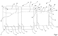
- the base body 8 which is flat in the basic state shown, of a folding box 9, which in a folded state defines an inner pocket for accommodating removable, light-sensitive cloths, is formed in one piece and comprises in particular a first panel 1, a second panel 2, a third panel 3 , a fourth panel 4, a fifth panel 5, a sixth panel 6 and a seventh panel 7, which are laterally separated from one another by longitudinal fold lines 10-15.
- the first, third, fifth and seventh panels 1, 3, 5, 7 have essentially the same width, the fifth and seventh panels 5, 7 having a somewhat smaller width, approximately by the thickness or twice the thickness of the flat base body 8 reduced.
- the second, fourth and sixth panels 2, 4, 6 have essentially the same width, the sixth panel 6 having a somewhat smaller width.
- upper flaps 16 and lower flaps 17 are articulated on an upper horizontal folding line 18 and on a lower horizontal folding line 19, so that the upper flaps 16 have upper walls and the lower flaps 17 lower Can form walls by folding them at right angles along the respective fold lines and gluing them together, for example.
- a tear line 20 in the form of a perforated line leads from the first panel 1 through the second panel 2 to the third panel 3 and adjoins a central horizontal fold line 22 in the fourth panel 4 to provide a tear-open hinged cover 23.
- the panels five, six and seven 5, 6, 7 can each be folded inwards at right angles over the respective longitudinal fold lines 13, 14, 15 such that they are inside the four, three, two and one 4 through the panels , 3, 2, 1 formed outer walls, whereby a spirally folded folding box 9 is realized.
- the upper edge 24 of the sixth panel is arranged above the tear line 20 in the second panel - represented by a dotted line 25, which represents a projection of this tear line 20 in the second panel 2 in the folded state - in order to provide a light protection wall 26.
- the lower edge 27 the sixth panel is arranged slightly above the lower horizontal fold line 19, which does not impair the light protection function.
- the fifth and seventh panels 5, 7 have guide elements 28, 29 projecting longitudinally beyond the sixth panel 6, which guide the hinged lid 23 when opening and closing and finally engage in the folded state (not shown further here).
- the guide elements 28, 29 prevent the hinged lid 23 from opening by itself, or from mechanical tension, for example in the middle horizontal fold line 22, from opening at least over an angle, starting from the light between the hinged lid 23 and the light protection wall 26 could kick.
- the guide elements 28, 29 are each divided by tear lines 30, 31 in the form of perforated lines into a part 28a, 29a, which cannot be detached from the fifth or seventh panel 5, 7, and a complementary detachable part 28b, 29b, which - here not shown - folded state in the hinged cover 23, in particular in the panels one 1 and three 3, glued, whereby the detachable parts 28b, 29b interact with the non-detachable parts 28a, 29a for guiding and latching the hinged cover 23, in particular along of the tear lines 30, 31.
- the tear lines 30, 31 in the fifth and seventh panels 5, 7 in the folded state are partially congruent with the tear line 20 in the first and third panels 1, 3, so that tear lines 20, 30, 31 are torn simultaneously can be.
- the tear lines 30, 31 in the fifth and seventh panels 5, 7 can protrude below the tear lines 2 in the first and third panels 1, 3 in the folded state, for light protection by the detachable parts 28b, 29b when the hinged lid is open 23.
- the tear lines 30, 31 could, for example, be drawn further down or unloaded further down.
- the longitudinal fold lines 14, 15 of the sixth panel 6 in the region of the light protection wall 26 are interrupted by arcuate holding elements 32, 33 protruding laterally from the sixth panel 6. These rub when opening and closing the hinged lid 23 in the folded state on the inside of the hinged lid 23 and thus stabilize it.
- the longitudinal folding lines 14, 15 which lie against the sixth panel 6 and define it are interrupted by recesses 34 which are elongated and which curvature in particular of the fifth, sixth and seventh panels 5, 6, 7 by reducing the mechanical hysteresis of the folding lines 14, 15 reduce when folding.
- the tear line 20 furthermore has, in the second panel 2, a bulge 35 which overlaps the light protection wall 26 and which, in the folded state (not shown here), serves to provide a supported engagement point.
- the folding box can be made of paper, cardboard and / or plastic.
Landscapes
- Engineering & Computer Science (AREA)
- Mechanical Engineering (AREA)
- Cartons (AREA)
Description
- Die vorliegende Erfindung betrifft eine Faltschachtel aus einem einstückigen, im Grundzustand flachen Grundkörper, welche in einem Faltzustand eine innere Tasche zur Aufnahme von herausnehmbaren, lichtempfindlichen Tüchern definiert, umfassend mindestens fünf Paneele die lateral voneinander durch longitudinale Faltlinien separiert sind, wobei das erste, dritte und fünfte Paneel im Wesentlichen die gleiche Breite aufweisen, und das zweite und vierte Paneel im Wesentlichen die gleiche Breite aufweisen, und wobei am ersten bis vierten Paneel obere und untere Laschen an einer oberen bzw. unteren horizontalen Faltlinie angelenkt sind, so dass die oberen und unteren Laschen obere bzw. untere Wände bilden können, wobei eine Aufreißlinie vom ersten Paneel durch das zweite Paneel zum dritten Paneel führt und an eine mittlere horizontale Faltlinie im vierten Paneel grenzt, zur Bereitstellung eines aufreißbaren Klappdeckels.
- Im Stand der Technik sind Schachteln zur Aufnahme lichtempfindlicher Tücher bekannt. Diese Schachteln lassen jedoch normalerweise im geöffneten Zustand einen ungehinderten Einfall von Licht durch die, zur Entnahme der Tücher vorgesehene, Öffnung auf den Inhalt zu. Außerdem kann eine geschlossene Schachtel sich häufig, beispielsweise aufgrund mechanischer Spannung im Bereich eines Deckelteils, unbeabsichtigt teilweise oder vollständig öffnen, wodurch ebenfalls ein unerwünschter Lichteinfall ermöglicht ist. Die Druckschrift
FR 2 818 958 A1 - Aufgabe der vorliegenden Erfindung ist es, eine verbesserte Faltschachtel bereitzustellen.
- In einem ersten Aspekt richtet sich die vorliegende Erfindung auf eine solche Faltschachtel nach Anspruch 1.
- Dadurch wird eine Faltschachtel mit verbesserter mechanischer Integrität bereitgestellt, bei der zudem aufgrund der doppelt ausgeführten Wand weniger Licht in den Innenbereich der Faltschachtel eindringen kann.
- Eine bevorzugte Ausführungsform der Erfindung sieht vor, dass eine obere Kante des sechsten Paneels oberhalb der Abrisslinie im zweiten Paneel angeordnet ist, zur Bereitstellung einer Lichtschutzwand.
- Dadurch wird insbesondere bei Lagerung von lichtempfindlichen Inhalt, der in den Bereich der horizontalen Aufreißlinie ragt, ermöglicht, den Klappdeckel zu öffnen und Inhalt zu entnehmen, ohne dass direkter Lichteinfall auf den Inhalt möglich ist, oder wobei dieser zumindest stark vermindert wird.
- Weiter bevorzugt ist eine untere Kante des sechsten Paneels oberhalb der unteren horizontalen Faltlinie angeordnet.
- Dadurch kann insbesondere fertigungstechnisch Material eingespart werden, da die Lichtschutzfunktion des sechsten Paneels vor allem durch den über die horizontale Aufreißlinie ragenden Teil erfüllt wird. Es ist insbesondere zu diesem Zweck nicht notwendig, dass sich im gefalteten Zustand das sechste Paneel bis zur unteren horizontalen Faltlinie erstreckt.
- Erfindungsgemäß weisen das fünfte und siebte Paneel longitudinal über das sechste Paneel ragende Leitelemente auf, zum Leiten und Einrasten des Klappdeckels beim Öffnen und Schließen.
- Dadurch wird gleichzeitig eine Einrastfunktion bereitgestellt, die zusammen mit der Lichtschutzfunktion des sechsten Paneels einen verbesserten Lichtschutz bereitstellt, da der Klappdeckel sich weniger einfach von alleine, beispielsweise durch mechanische Spannungen in der oberen horizontalen Faltlinie des vierten Paneels, öffnen kann. Somit wird lichtempfindlicher Inhalt besser vor Lichteinfall geschützt.
- Diese Ausführungsform wird vorzugsweise verbessert, indem die Leitelemente durch Aufreißlinien jeweils unterteilt sind in einen von dem fünften bzw. siebten Paneel unlösbaren Teil und einen dazu komplementären lösbaren Teil, zum Ankleben in den Klappdeckel und zum Leiten und Einrasten mit dem unlösbaren Teil.
- Wenn der Klappdeckel nach erstmaligen Öffnen wieder geschlossen ist, liegen der lösbare und der unlösbare Teil nur durch die geöffnete Aufreißlinie getrennt eng aneinander an und stellen somit eine Einrastfunktion bereit. Dies gilt umso mehr, wenn die lösbaren Teile konkave oder konvexe, zu den unlösbaren Teilen komplementäre Formen aufweisen. Auch vor dem Einrasten in der geschlossenen Stellung reiben die Kanten der lösbaren und unlösbaren Kanten dabei aneinander, und leiten dadurch die Bewegung beim Öffnen oder Schließen, was die Betätigung der Faltschachtel weiter vereinfacht.
- Auch das Einfügen von Inhalt, wie lichtempfindlicher Tücher, in das Innere der Faltschachtel, wird dadurch vereinfacht, da der lösbare Teil an die Innenseite des Klappdeckels geklebt wird und somit nicht frei im Bereich des Klappdeckels abstehen kann. Die Befüllung der Faltschachtel geschieht, indem der Inhalt durch die die noch parallel zu den Paneelen eins bis vier ausgerichteten oberen Laschen hindurch in die Faltschachtel eingeführt werden, wobei nach Innen abstehende Teile der Leitelemente blockierend im Weg stehen könnten. Insbesondere automatisierte Befüllungen könnten dadurch erheblich behindert werden.
- Erfindungsgemäß ragen die Aufreißlinien im fünften und siebten Paneel im Faltzustand unter die Aufreißlinien im ersten bzw. dritten Paneel, zum Lichtschutz durch die lösbaren Teile bei aufgeklapptem Klappdeckel.
- Dadurch wird ermöglicht, dass selbst bei teilweise oder vollständig geöffnetem Klappdeckel noch die im Klappdeckel angeklebten lösbaren Teile in den offenen Spalt zwischen Klappdeckel und der Lichtschutzwand bzw. den Leitelementen ragen, so dass sie dort ebenfalls zum verbesserten Lichtschutz des Inneren der Faltschachtel beitragen.
- Eine weitere Verbesserung der Erfindung sieht vor, dass mindestens eine der longitudinalen Faltlinien des sechsten Paneels im Bereich der Lichtschutzwand durch ein lateral aus dem sechsten Paneel ragendes, vorzugsweise bogenförmiges, Halteelement unterbrochen ist.
- Dadurch wird, wenn im Faltzustand das fünfte und siebte Paneel rechtwinklig abgeknickt sind, erreicht, dass das Halteelement parallel zum sechsten Paneel seitlich davon absteht, also senkrecht auf dem siebten bzw. fünften Paneel, und in den Klappdeckel eingreift um diesen in der geschlossenen Stellung zu halten.
- Besonders bevorzugt ist mindestens eine der longitudinalen Faltlinien des sechsten Paneels durch Ausnehmungen unterbrochen.
- Dadurch wird erreicht, dass die jeweilige Faltlinie oder beide Faltlinien strukturell geschwächt werden, also leichter zu falten sind, und dass durch die jeweilige Faltlinie(n) eine geringere Spannung auf den angrenzenden Paneelen lastet, dass diese also weniger gewölbt vorstehen, sondern eher vollständig in rechtwinklig zueinander orientierten flachen Ebenen angeordnet sind. Dies ist insbesondere vorteilhaft da das fünfte, sechste und siebte Paneel auf der Innenseite der Faltschachtel angeordnet sind und unmittelbar an das dritte, zweite bzw. erste Paneel anliegen, wobei eine Wölbung fertigungstechnische Toleranzen überschreiten könnte.
- Insbesondere bevorzugt ist die Oberkante des sechsten Paneels mindestens 5mm, 10mm, 15mm oder 20mm über der Aufreißlinie im zweiten Paneel angeordnet. Gleichermaßen bevorzugt ist die Oberkante des sechsten Paneels auf etwa 25%, 50%, 75% oder 100% der Höhe der Leitelemente oberhalb der Aufreißlinie angeordnet ist.
- Dadurch werden bevorzugte Höhen der Lichtschutzwand realisiert. Wenn die Leitelemente abgerundete Ecken aufweisen, ist es weiterhin bevorzugt, die Oberkante des sechsten Paneels am Ansatz der abgerundeten Ecken anzuordnen.
- Besonders bevorzugt weist die Aufreißlinie im zweiten Paneel eine die Lichtschutzwand überlappende Ausbuchtung auf, zur Bereitstellung einer abgestützten Eingriffsstelle.
- Dadurch kann die Aufreißlinie leicht geöffnet werden, ohne Teile der Faltschachtel oder des Klappdeckels zu beschädigen.
- Nachfolgend wird die Erfindung anhand der Figur weiter erläutert.
- Gemäß Figur ist der im dargestellten Grundzustand flache Grundkörper 8 einer Faltschachtel 9, welche in einem Faltzustand eine innere Tasche zur Aufnahme von herausnehmbaren, lichtempfindlichen Tüchern definiert, einstückig ausgebildet, und umfasst insbesondere ein erstes Paneel 1, ein zweites Paneel 2, ein drittes Paneel 3, ein viertes Paneel 4, ein fünftes Paneel 5, ein sechstes Paneel 6 und ein siebtes Paneel 7, die lateral voneinander durch longitudinale Faltlinien 10-15 separiert sind.
- Das erste, dritte, fünfte und siebte Paneel 1, 3, 5, 7 weist im Wesentlichen die gleiche Breite auf, wobei das fünfte und siebte Paneel 5, 7 eine etwas geringere Breite besitzen, und zwar in etwa um die Dicke oder die doppelte Dicke des flächigen Grundkörpers 8 verringert. Ebenso weisen das zweite, vierte und sechste Paneel 2, 4, 6 im Wesentlichen die gleiche Breite auf, wobei das sechste Paneel 6 eine etwas geringere Breite besitzt.
- Am ersten bis vierten Paneel 1, 2, 3, 4 sind obere Laschen 16 und untere Laschen 17 an einer oberen horizontalen Faltlinie 18 bzw. an einer unteren horizontalen Faltlinie 19 angelenkt, so dass die oberen Laschen 16 obere Wände und die unteren Laschen 17 untere Wände bilden können, indem sie entlang der jeweiligen Faltlinien rechtwinklig gefaltet und beispielsweise jeweils miteinander verklebt werden.
- Eine Aufreißlinie 20 in Form einer perforierten Linie führt vom ersten Paneel 1 durch das zweite Paneel 2 zum dritten Paneel 3 und grenzt an eine mittlere horizontale Faltlinie 22 im vierten Paneel 4 an, zur Bereitstellung eines aufreißbaren Klappdeckels 23.
- Dadurch können die Paneele fünf, sechs und sieben 5, 6, 7 so jeweils in rechten Winkeln über die jeweiligen longitudinalen Faltlinien 13, 14, 15 nach innen gefaltet werden, dass sie im Inneren der durch die Paneele vier, drei, zwei und eins 4, 3, 2, 1 gebildeten Außenwände anliegen, wodurch eine spiralförmig gefaltete Faltschachtel 9 verwirklicht wird.
- Die obere Kante 24 des sechsten Paneels ist oberhalb der Abrisslinie 20 im zweiten Paneel - dargestellt mittels einer gepunkteten Linie 25, die eine Projektion dieser Abrisslinie 20 im zweiten Paneel 2 im gefalteten Zustand darstellt - angeordnet, zur Bereitstellung einer Lichtschutzwand 26. Die untere Kante 27 des sechsten Paneels ist geringfügig oberhalb der unteren horizontalen Faltlinie 19 angeordnet, was die Lichtschutzfunktion nicht beeinträchtigt.
- Das fünfte und siebte Paneel 5, 7 weisen longitudinal über das sechste Paneel 6 ragende Leitelemente 28, 29 auf, die im - hier nicht weiter dargestellten - Faltzustand den Klappdeckel 23 beim Öffnen und Schließen leiten und final einrasten lassen. Insbesondere wird durch die Leitelemente 28, 29 verhindert, dass der Klappdeckel 23 sich von alleine, oder durch eine mechanische Spannung beispielsweise in der mittleren horizontalen Faltlinie 22, öffnet, jedenfalls über einen Winkel hinweg öffnet, ab dem Licht zwischen den Klappdeckel 23 und die Lichtschutzwand 26 treten könnte.
- Die Leitelemente 28, 29 sind jeweils durch Aufreißlinien 30, 31 in Form perforierter Linien in jeweils einen von dem fünften bzw. siebten Paneel 5, 7 unlösbaren Teil 28a, 29a und einen dazu komplementären lösbaren Teil 28b, 29b, unterteilt, welche im - hier nicht weiter dargestellten - Faltzustand in den Klappdeckel 23, insbesondere in die Paneele eins 1 und drei 3, geklebt sind, wodurch die lösbaren Teile 28b, 29b mit den unlösbaren Teilen 28a, 29a zum Leiten und Einrasten des Klappdeckels 23 zusammenwirken, und zwar insbesondere entlang der Aufreißlinien 30, 31. Dabei sind die Aufreißlinien 30, 31 im fünften und siebten Paneel 5, 7 im Faltzustand teilweise deckungsgleich sind mit der Aufreißlinie 20 im ersten bzw. dritten Paneel 1, 3, so dass Aufreißlinien 20, 30, 31 gleichzeitig aufgerissen werden können.
- Alternativ - hier nicht weiter dargestellt - können die Aufreißlinien 30, 31 im fünften und siebten Paneel 5, 7 im Faltzustand unterhalb die Aufreißlinien 2 im ersten bzw. dritten Paneel 1, 3 ragen, zum Lichtschutz durch die lösbaren Teile 28b, 29b bei aufgeklapptem Klappdeckel 23. Dazu könnten beispielsweise die Aufreißlinien 30, 31 weiter nach unten gezogen sein oder bauchig weiter nach unten ausladen.
- Die longitudinalen Faltlinien 14, 15 des sechsten Paneels 6 im Bereich der Lichtschutzwand 26 sind durch lateral aus dem sechsten Paneel 6 ragende, bogenförmige Halteelemente 32, 33 unterbrochen. Diese reiben sich beim Öffnen und Schließen des Klappdeckels 23 im Faltzustand an der Innenseite des Klappdeckels 23 und stabilisieren diesen somit.
- Die am sechsten Paneel 6 anliegenden und dieses definierenden longitudinalen Faltlinien 14, 15 sind durch Ausnehmungen 34 unterbrochen, welche länglich ausgeführt sind und welche eine Wölbung insbesondere des fünften, sechsten und siebten Paneels 5, 6, 7 durch Reduzierung der mechanischen Hysterese der Faltlinien 14, 15 beim Falten verringern.
- Die Aufreißlinie 20 weist des Weiteren im zweiten Paneel 2 eine, die Lichtschutzwand 26 überlappende, Ausbuchtung 35 auf, welche im - hier nicht dargestellten - Faltzustand zur Bereitstellung einer abgestützten Eingriffsstelle dient.
- Die Erfindung ist nicht beschränkt auf die voranstehenden Ausführungsbeispiele. Sie erstreckt sich vielmehr noch auf weitere Ausbildungsformen, die von den nachstehenden Patentansprüchen mit umfasst werden. So kann die Faltschachtel beispielsweise aus Papier, Pappe und / oder Kunststoff gefertigt sein.
Claims (9)
- Faltschachtel (9) aus einem einstückigen, im Grundzustand flachen Grundkörper (8), welche in einem Faltzustand eine innere Tasche zur Aufnahme von herausnehmbaren, lichtempfindlichen Tüchern definiert, umfassend
mindestens fünf Paneele (1, 2, 3, 4, 5) die lateral voneinander durch longitudinale Faltlinien (10, 11, 12, 13) separiert sind,
wobei das erste, dritte und fünfte Paneel (1, 3, 5) im Wesentlichen die gleiche Breite aufweisen, und das zweite und vierte Paneel (2, 4) im Wesentlichen die gleiche Breite aufweisen, und wobei am ersten bis vierten Paneel (1, 2, 3, 4) obere und untere Laschen (16, 17) an einer oberen bzw. unteren horizontalen Faltlinie (18, 19) angelenkt sind, so dass die oberen und unteren Laschen (16, 17) obere bzw. untere Wände bilden können,
wobei eine Aufreißlinie (20) vom ersten Paneel (1) durch das zweite Paneel (2) zum dritten Paneel (3) führt und an eine mittlere horizontale Faltlinie (22) im vierten Paneel (4) grenzt, zur Bereitstellung eines aufreißbaren Klappdeckels (23),
wobei
die mindestens fünf Paneele (1, 2, 3, 4, 5) mindestens sieben Paneele (1, 2, 3, 4, 5, 6, 7) sind, wobei das sechste Paneel (6) im Wesentlichen die Breite des zweiten Paneels (2) aufweist, und das siebte Paneel (7) im Wesentlichen die gleiche oder eine geringere Breite aufweist wie das fünfte Paneel (5),
so dass die Paneele (1, 2, 3, 4, 5, 6, 7) entlang der sie separierenden longitudinalen Faltlinien (10, 11, 12, 13, 14, 15) spiralig in den Faltzustand zu der Faltschachtel (9) faltbar sind, derart dass die Paneele fünf, sechs und sieben (5, 6, 7) so jeweils in rechten Winkeln über die jeweiligen longitudinalen Faltlinien (13, 14, 15) nach innen gefaltet werden, dass sie an den Innenseiten der durch die Paneele drei, zwei und eins (3, 2, 1) gebildeten Außenwände anliegen, wodurch eine spiralförmig gefaltete Faltschachtel (9) verwirklicht wird, wobei das fünfte und siebte Paneel (5, 7) longitudinal über das sechste Paneel (6) ragende Leitelemente (28, 29) aufweisen, zum Leiten und Einrasten des Klappdeckels (23) beim Öffnen und Schließen und wobei
die Leitelemente (28, 29) durch Aufreißlinien (30, 31) jeweils unterteilt sind in einen von dem fünften bzw. siebten Paneel (5; 7) unlösbaren Teil (28a; 29a) und einen dazu komplementären lösbaren Teil (28b; 29b), zum Ankleben in den Klappdeckel und zum Leiten und Einrasten mit dem unlösbaren Teil (28a; 29a),
dadurch gekennzeichnet, dass
die Aufreißlinien (30, 31) im fünften und siebten Paneel (5, 7) im Faltzustand unter die Aufreißlinie (20) im ersten bzw. dritten Paneel (1; 3) ragen, zum Lichtschutz durch die lösbaren Teile (28b, 29b) bei aufgeklapptem Klappdeckel (23). - Faltschachtel (9) nach Anspruch 1, dadurch gekennzeichnet, dass eine obere Kante (24) des sechsten Paneels (6) oberhalb der Abrisslinie (20) im zweiten Paneel (2) angeordnet ist, zur Bereitstellung einer Lichtschutzwand (26).
- Faltschachtel (9) nach einem der vorherstehenden Ansprüche, dadurch gekennzeichnet, dass eine untere Kante (27) des sechsten Paneels (6) oberhalb der unteren horizontalen Faltlinie (19) angeordnet ist.
- Faltschachtel (9) nach Anspruch 2, dadurch gekennzeichnet, dass mindestens eine der longitudinalen Faltlinien (14; 15) des sechsten Paneels (6) im Bereich der Lichtschutzwand (26) durch ein lateral aus dem sechsten Paneel (6) ragendes, vorzugsweise bogenförmiges, Halteelement (32; 33) unterbrochen ist.
- Faltschachtel (9) nach einem der vorherstehenden Ansprüche, dadurch gekennzeichnet, dass mindestens eine der longitudinalen Faltlinien (14; 15) des sechsten Paneels durch Ausnehmungen (34) unterbrochen ist.
- Faltschachtel (9) nach einem der vorherstehenden Ansprüche, dadurch gekennzeichnet, dass die Oberkante (24) des sechsten Paneels (6) mindestens 5mm, 10mm, 15mm oder 20mm oberhalb der Aufreißlinie (20) im zweiten Paneel (2) angeordnet ist.
- Faltschachtel (9) nach einem der vorherstehenden Ansprüche, dadurch gekennzeichnet, dass die Oberkante (24) des sechsten Paneels (6) auf etwa 25%, 50%, 75% oder 100% der Höhe (36) der Leitelemente (28, 29) oberhalb der Aufreißlinie (20) im zweiten Paneel (2) angeordnet ist.
- Faltschachtel (9) nach einem der vorherstehenden Ansprüche, dadurch gekennzeichnet, dass die Aufreißlinie (20) im zweiten Paneel eine, die Lichtschutzwand 26 überlappende, Ausbuchtung (35) aufweist, zur Bereitstellung einer abgestützten Eingriffstelle.
- Faltschachtelsystem, umfassend eine Faltschachtel nach einem der Ansprüche 1-8 im Faltzustand, die lichtempfindlichen Inhalt, insbesondere lichtempfindliche Tücher, enthält.
Priority Applications (1)
| Application Number | Priority Date | Filing Date | Title |
|---|---|---|---|
| PL18186943T PL3450341T3 (pl) | 2017-09-05 | 2018-08-02 | Składane pudełko z ochroną przed światłem |
Applications Claiming Priority (1)
| Application Number | Priority Date | Filing Date | Title |
|---|---|---|---|
| DE102017215627.9A DE102017215627A1 (de) | 2017-09-05 | 2017-09-05 | Faltschachtel mit Lichtschutz |
Publications (2)
| Publication Number | Publication Date |
|---|---|
| EP3450341A1 EP3450341A1 (de) | 2019-03-06 |
| EP3450341B1 true EP3450341B1 (de) | 2020-04-15 |
Family
ID=63144825
Family Applications (1)
| Application Number | Title | Priority Date | Filing Date |
|---|---|---|---|
| EP18186943.9A Active EP3450341B1 (de) | 2017-09-05 | 2018-08-02 | Faltschachtel mit lichtschutz |
Country Status (3)
| Country | Link |
|---|---|
| EP (1) | EP3450341B1 (de) |
| DE (1) | DE102017215627A1 (de) |
| PL (1) | PL3450341T3 (de) |
Family Cites Families (12)
| Publication number | Priority date | Publication date | Assignee | Title |
|---|---|---|---|---|
| US2320289A (en) * | 1942-07-14 | 1943-05-25 | Richardson Taylor Globe Corp | Carton |
| US2396150A (en) * | 1943-02-01 | 1946-03-05 | Robertson Paper Box Co | Box |
| US2930516A (en) * | 1959-04-21 | 1960-03-29 | Gen Aniline & Film Corp | Paperboard container |
| US3708108A (en) * | 1971-09-22 | 1973-01-02 | Burt Co Inc F | Flip top carton |
| DE7821998U1 (de) * | 1978-07-22 | 1978-10-26 | Europa Carton Ag | Flacher faltschachtel-zuschnitt und daraus hergestellte Faltschachtel |
| DE3911972A1 (de) * | 1988-11-19 | 1990-10-25 | Kloeckner Pentapack | Faltschachtel aus karton zur aufnahme von uebereinander gestapelten hygienetuechern |
| EP0791853B1 (de) * | 1996-02-22 | 2002-12-18 | Agfa-Gevaert | Wiederverschliessbare Packung für photographische Blätter |
| DE29607374U1 (de) * | 1996-04-24 | 1996-07-11 | Mann, Wolfgang, Dipl.-Ing., 37281 Wanfried | Geschlossener Faltschachtelkörper mit doppelter Deckelteilauslegung, mit integriertem Einfach-Tragegriff und erhöhter Tragestabilität im Griffbereich, für leichte und mittelschwere Produkte |
| DE29609247U1 (de) * | 1996-05-23 | 1996-08-22 | Mann, Wolfgang, Dipl.-Ing., 37281 Wanfried | Geschlossener Faltschachtelkörper mit doppelter Deckelteilauslegung, mit integriertem Einfach-Tragegriff und erhöhter Tragestabilität im Griffbereich, für mittelschwere und schwere Produkte |
| FR2818958B1 (fr) * | 2000-12-28 | 2003-06-27 | Finega | Etui de conditionnement preforme et flan pour son obtention |
| DE102006032008A1 (de) * | 2006-07-10 | 2008-01-24 | Henkel Kgaa | Klappschachtel mit leistenverstärktem Griffausschnitt |
| AU2015367428B2 (en) * | 2014-12-19 | 2019-12-19 | Société des Produits Nestlé S.A. | A blank for a reclosable container |
-
2017
- 2017-09-05 DE DE102017215627.9A patent/DE102017215627A1/de not_active Withdrawn
-
2018
- 2018-08-02 PL PL18186943T patent/PL3450341T3/pl unknown
- 2018-08-02 EP EP18186943.9A patent/EP3450341B1/de active Active
Non-Patent Citations (1)
| Title |
|---|
| None * |
Also Published As
| Publication number | Publication date |
|---|---|
| EP3450341A1 (de) | 2019-03-06 |
| PL3450341T3 (pl) | 2020-11-02 |
| DE102017215627A1 (de) | 2019-03-07 |
Similar Documents
| Publication | Publication Date | Title |
|---|---|---|
| EP0650907B1 (de) | Klappschachtel, insbesondere für Zigaretten | |
| EP2354020B1 (de) | Schachtel, insbesondere Faltschachtel | |
| DE3329455A1 (de) | Kappenschachtel fuer zigaretten oder dergleichen | |
| DE3340798C2 (de) | Verpackung mit einem Garantieverschluß in Form einer Schachtel aus Karton | |
| EP3450341B1 (de) | Faltschachtel mit lichtschutz | |
| DE19519437A1 (de) | Wiederverschließbare Faltschachtel mit Öffnungssicherung | |
| DE3624345A1 (de) | Cigarettenschachtel | |
| EP0121040A1 (de) | Faltschachtel | |
| DE9306209U1 (de) | Faltschachtel aus einem gefalteten Zuschnitt | |
| EP0108990A2 (de) | Faltschachtel | |
| DE9316489U1 (de) | Kappenschachtel | |
| EP2055644A1 (de) | Beutel | |
| DE29814612U1 (de) | Kappenschachtel mit Wiederverschluß | |
| DE102012110145A1 (de) | Transportverpackung mit stabilem Boden | |
| DE2425694A1 (de) | Stuelpdeckelschachtel | |
| DE2350023A1 (de) | Faltschachtel mit einem einsatz | |
| DE4117353C2 (de) | ||
| DE102015003067B4 (de) | Verpackung für zylinderförmige Gegenstände und Zuschnitt dafür | |
| EP3118138B1 (de) | Verpackung und zuschnitt zur herstellung einer verpackung | |
| CH639340A5 (en) | Folding box with a tear-off pouring opening | |
| DE29503238U1 (de) | Faltschachtel mit wiederverschließbarer Schüttklappe | |
| DE8228288U1 (de) | Staubdichte Faltschachtel | |
| DE8809364U1 (de) | Faltschachtel als Displaybehälter | |
| DE1761040B2 (de) | Faltschachtel fuer die verpackung von fliessfaehigen, trockenen produkten | |
| DE202017105021U1 (de) | Wiederverschließbare Faltschachtel |
Legal Events
| Date | Code | Title | Description |
|---|---|---|---|
| PUAI | Public reference made under article 153(3) epc to a published international application that has entered the european phase |
Free format text: ORIGINAL CODE: 0009012 |
|
| STAA | Information on the status of an ep patent application or granted ep patent |
Free format text: STATUS: REQUEST FOR EXAMINATION WAS MADE |
|
| 17P | Request for examination filed |
Effective date: 20180802 |
|
| AK | Designated contracting states |
Kind code of ref document: A1 Designated state(s): AL AT BE BG CH CY CZ DE DK EE ES FI FR GB GR HR HU IE IS IT LI LT LU LV MC MK MT NL NO PL PT RO RS SE SI SK SM TR |
|
| AX | Request for extension of the european patent |
Extension state: BA ME |
|
| GRAP | Despatch of communication of intention to grant a patent |
Free format text: ORIGINAL CODE: EPIDOSNIGR1 |
|
| STAA | Information on the status of an ep patent application or granted ep patent |
Free format text: STATUS: GRANT OF PATENT IS INTENDED |
|
| INTG | Intention to grant announced |
Effective date: 20191217 |
|
| GRAS | Grant fee paid |
Free format text: ORIGINAL CODE: EPIDOSNIGR3 |
|
| GRAA | (expected) grant |
Free format text: ORIGINAL CODE: 0009210 |
|
| STAA | Information on the status of an ep patent application or granted ep patent |
Free format text: STATUS: THE PATENT HAS BEEN GRANTED |
|
| AK | Designated contracting states |
Kind code of ref document: B1 Designated state(s): AL AT BE BG CH CY CZ DE DK EE ES FI FR GB GR HR HU IE IS IT LI LT LU LV MC MK MT NL NO PL PT RO RS SE SI SK SM TR |
|
| REG | Reference to a national code |
Ref country code: CH Ref legal event code: EP |
|
| REG | Reference to a national code |
Ref country code: DE Ref legal event code: R096 Ref document number: 502018001195 Country of ref document: DE |
|
| REG | Reference to a national code |
Ref country code: IE Ref legal event code: FG4D Free format text: LANGUAGE OF EP DOCUMENT: GERMAN |
|
| REG | Reference to a national code |
Ref country code: AT Ref legal event code: REF Ref document number: 1257015 Country of ref document: AT Kind code of ref document: T Effective date: 20200515 |
|
| REG | Reference to a national code |
Ref country code: NL Ref legal event code: MP Effective date: 20200415 |
|
| REG | Reference to a national code |
Ref country code: LT Ref legal event code: MG4D |
|
| PG25 | Lapsed in a contracting state [announced via postgrant information from national office to epo] |
Ref country code: PT Free format text: LAPSE BECAUSE OF FAILURE TO SUBMIT A TRANSLATION OF THE DESCRIPTION OR TO PAY THE FEE WITHIN THE PRESCRIBED TIME-LIMIT Effective date: 20200817 Ref country code: LT Free format text: LAPSE BECAUSE OF FAILURE TO SUBMIT A TRANSLATION OF THE DESCRIPTION OR TO PAY THE FEE WITHIN THE PRESCRIBED TIME-LIMIT Effective date: 20200415 Ref country code: FI Free format text: LAPSE BECAUSE OF FAILURE TO SUBMIT A TRANSLATION OF THE DESCRIPTION OR TO PAY THE FEE WITHIN THE PRESCRIBED TIME-LIMIT Effective date: 20200415 Ref country code: NO Free format text: LAPSE BECAUSE OF FAILURE TO SUBMIT A TRANSLATION OF THE DESCRIPTION OR TO PAY THE FEE WITHIN THE PRESCRIBED TIME-LIMIT Effective date: 20200715 Ref country code: GR Free format text: LAPSE BECAUSE OF FAILURE TO SUBMIT A TRANSLATION OF THE DESCRIPTION OR TO PAY THE FEE WITHIN THE PRESCRIBED TIME-LIMIT Effective date: 20200716 Ref country code: SE Free format text: LAPSE BECAUSE OF FAILURE TO SUBMIT A TRANSLATION OF THE DESCRIPTION OR TO PAY THE FEE WITHIN THE PRESCRIBED TIME-LIMIT Effective date: 20200415 Ref country code: IS Free format text: LAPSE BECAUSE OF FAILURE TO SUBMIT A TRANSLATION OF THE DESCRIPTION OR TO PAY THE FEE WITHIN THE PRESCRIBED TIME-LIMIT Effective date: 20200815 Ref country code: NL Free format text: LAPSE BECAUSE OF FAILURE TO SUBMIT A TRANSLATION OF THE DESCRIPTION OR TO PAY THE FEE WITHIN THE PRESCRIBED TIME-LIMIT Effective date: 20200415 |
|
| PG25 | Lapsed in a contracting state [announced via postgrant information from national office to epo] |
Ref country code: HR Free format text: LAPSE BECAUSE OF FAILURE TO SUBMIT A TRANSLATION OF THE DESCRIPTION OR TO PAY THE FEE WITHIN THE PRESCRIBED TIME-LIMIT Effective date: 20200415 Ref country code: RS Free format text: LAPSE BECAUSE OF FAILURE TO SUBMIT A TRANSLATION OF THE DESCRIPTION OR TO PAY THE FEE WITHIN THE PRESCRIBED TIME-LIMIT Effective date: 20200415 Ref country code: BG Free format text: LAPSE BECAUSE OF FAILURE TO SUBMIT A TRANSLATION OF THE DESCRIPTION OR TO PAY THE FEE WITHIN THE PRESCRIBED TIME-LIMIT Effective date: 20200715 Ref country code: LV Free format text: LAPSE BECAUSE OF FAILURE TO SUBMIT A TRANSLATION OF THE DESCRIPTION OR TO PAY THE FEE WITHIN THE PRESCRIBED TIME-LIMIT Effective date: 20200415 |
|
| PG25 | Lapsed in a contracting state [announced via postgrant information from national office to epo] |
Ref country code: AL Free format text: LAPSE BECAUSE OF FAILURE TO SUBMIT A TRANSLATION OF THE DESCRIPTION OR TO PAY THE FEE WITHIN THE PRESCRIBED TIME-LIMIT Effective date: 20200415 |
|
| REG | Reference to a national code |
Ref country code: DE Ref legal event code: R097 Ref document number: 502018001195 Country of ref document: DE |
|
| PG25 | Lapsed in a contracting state [announced via postgrant information from national office to epo] |
Ref country code: DK Free format text: LAPSE BECAUSE OF FAILURE TO SUBMIT A TRANSLATION OF THE DESCRIPTION OR TO PAY THE FEE WITHIN THE PRESCRIBED TIME-LIMIT Effective date: 20200415 Ref country code: SM Free format text: LAPSE BECAUSE OF FAILURE TO SUBMIT A TRANSLATION OF THE DESCRIPTION OR TO PAY THE FEE WITHIN THE PRESCRIBED TIME-LIMIT Effective date: 20200415 Ref country code: EE Free format text: LAPSE BECAUSE OF FAILURE TO SUBMIT A TRANSLATION OF THE DESCRIPTION OR TO PAY THE FEE WITHIN THE PRESCRIBED TIME-LIMIT Effective date: 20200415 Ref country code: RO Free format text: LAPSE BECAUSE OF FAILURE TO SUBMIT A TRANSLATION OF THE DESCRIPTION OR TO PAY THE FEE WITHIN THE PRESCRIBED TIME-LIMIT Effective date: 20200415 Ref country code: ES Free format text: LAPSE BECAUSE OF FAILURE TO SUBMIT A TRANSLATION OF THE DESCRIPTION OR TO PAY THE FEE WITHIN THE PRESCRIBED TIME-LIMIT Effective date: 20200415 Ref country code: CZ Free format text: LAPSE BECAUSE OF FAILURE TO SUBMIT A TRANSLATION OF THE DESCRIPTION OR TO PAY THE FEE WITHIN THE PRESCRIBED TIME-LIMIT Effective date: 20200415 |
|
| PLBE | No opposition filed within time limit |
Free format text: ORIGINAL CODE: 0009261 |
|
| STAA | Information on the status of an ep patent application or granted ep patent |
Free format text: STATUS: NO OPPOSITION FILED WITHIN TIME LIMIT |
|
| PG25 | Lapsed in a contracting state [announced via postgrant information from national office to epo] |
Ref country code: SK Free format text: LAPSE BECAUSE OF FAILURE TO SUBMIT A TRANSLATION OF THE DESCRIPTION OR TO PAY THE FEE WITHIN THE PRESCRIBED TIME-LIMIT Effective date: 20200415 |
|
| 26N | No opposition filed |
Effective date: 20210118 |
|
| PG25 | Lapsed in a contracting state [announced via postgrant information from national office to epo] |
Ref country code: MC Free format text: LAPSE BECAUSE OF FAILURE TO SUBMIT A TRANSLATION OF THE DESCRIPTION OR TO PAY THE FEE WITHIN THE PRESCRIBED TIME-LIMIT Effective date: 20200415 |
|
| PG25 | Lapsed in a contracting state [announced via postgrant information from national office to epo] |
Ref country code: LU Free format text: LAPSE BECAUSE OF NON-PAYMENT OF DUE FEES Effective date: 20200802 |
|
| REG | Reference to a national code |
Ref country code: BE Ref legal event code: MM Effective date: 20200831 |
|
| PG25 | Lapsed in a contracting state [announced via postgrant information from national office to epo] |
Ref country code: SI Free format text: LAPSE BECAUSE OF FAILURE TO SUBMIT A TRANSLATION OF THE DESCRIPTION OR TO PAY THE FEE WITHIN THE PRESCRIBED TIME-LIMIT Effective date: 20200415 |
|
| PG25 | Lapsed in a contracting state [announced via postgrant information from national office to epo] |
Ref country code: IE Free format text: LAPSE BECAUSE OF NON-PAYMENT OF DUE FEES Effective date: 20200802 Ref country code: BE Free format text: LAPSE BECAUSE OF NON-PAYMENT OF DUE FEES Effective date: 20200831 |
|
| REG | Reference to a national code |
Ref country code: CH Ref legal event code: PL |
|
| PG25 | Lapsed in a contracting state [announced via postgrant information from national office to epo] |
Ref country code: LI Free format text: LAPSE BECAUSE OF NON-PAYMENT OF DUE FEES Effective date: 20210831 Ref country code: CH Free format text: LAPSE BECAUSE OF NON-PAYMENT OF DUE FEES Effective date: 20210831 |
|
| PG25 | Lapsed in a contracting state [announced via postgrant information from national office to epo] |
Ref country code: TR Free format text: LAPSE BECAUSE OF FAILURE TO SUBMIT A TRANSLATION OF THE DESCRIPTION OR TO PAY THE FEE WITHIN THE PRESCRIBED TIME-LIMIT Effective date: 20200415 Ref country code: MT Free format text: LAPSE BECAUSE OF FAILURE TO SUBMIT A TRANSLATION OF THE DESCRIPTION OR TO PAY THE FEE WITHIN THE PRESCRIBED TIME-LIMIT Effective date: 20200415 Ref country code: CY Free format text: LAPSE BECAUSE OF FAILURE TO SUBMIT A TRANSLATION OF THE DESCRIPTION OR TO PAY THE FEE WITHIN THE PRESCRIBED TIME-LIMIT Effective date: 20200415 |
|
| PG25 | Lapsed in a contracting state [announced via postgrant information from national office to epo] |
Ref country code: MK Free format text: LAPSE BECAUSE OF FAILURE TO SUBMIT A TRANSLATION OF THE DESCRIPTION OR TO PAY THE FEE WITHIN THE PRESCRIBED TIME-LIMIT Effective date: 20200415 |
|
| P01 | Opt-out of the competence of the unified patent court (upc) registered |
Effective date: 20230530 |
|
| PGFP | Annual fee paid to national office [announced via postgrant information from national office to epo] |
Ref country code: IT Payment date: 20230825 Year of fee payment: 6 Ref country code: GB Payment date: 20230822 Year of fee payment: 6 |
|
| PGFP | Annual fee paid to national office [announced via postgrant information from national office to epo] |
Ref country code: PL Payment date: 20230721 Year of fee payment: 6 Ref country code: FR Payment date: 20230828 Year of fee payment: 6 Ref country code: DE Payment date: 20230821 Year of fee payment: 6 |