EP3448623B1 - Montagevorrichtung, verfahren zur steuerung der montagevorrichtung und verfahren zum herstellen in einer montagevorrichtung - Google Patents
Montagevorrichtung, verfahren zur steuerung der montagevorrichtung und verfahren zum herstellen in einer montagevorrichtung Download PDFInfo
- Publication number
- EP3448623B1 EP3448623B1 EP17737717.3A EP17737717A EP3448623B1 EP 3448623 B1 EP3448623 B1 EP 3448623B1 EP 17737717 A EP17737717 A EP 17737717A EP 3448623 B1 EP3448623 B1 EP 3448623B1
- Authority
- EP
- European Patent Office
- Prior art keywords
- axis
- linear
- mounting device
- carriage
- axis robot
- Prior art date
- Legal status (The legal status is an assumption and is not a legal conclusion. Google has not performed a legal analysis and makes no representation as to the accuracy of the status listed.)
- Active
Links
Images
Classifications
-
- B—PERFORMING OPERATIONS; TRANSPORTING
- B23—MACHINE TOOLS; METAL-WORKING NOT OTHERWISE PROVIDED FOR
- B23P—METAL-WORKING NOT OTHERWISE PROVIDED FOR; COMBINED OPERATIONS; UNIVERSAL MACHINE TOOLS
- B23P21/00—Machines for assembling a multiplicity of different parts to compose units, with or without preceding or subsequent working of such parts, e.g. with program control
- B23P21/002—Machines for assembling a multiplicity of different parts to compose units, with or without preceding or subsequent working of such parts, e.g. with program control the units stationary whilst being composed
-
- B—PERFORMING OPERATIONS; TRANSPORTING
- B23—MACHINE TOOLS; METAL-WORKING NOT OTHERWISE PROVIDED FOR
- B23P—METAL-WORKING NOT OTHERWISE PROVIDED FOR; COMBINED OPERATIONS; UNIVERSAL MACHINE TOOLS
- B23P19/00—Machines for simply fitting together or separating metal parts or objects, or metal and non-metal parts, whether or not involving some deformation; Tools or devices therefor so far as not provided for in other classes
- B23P19/04—Machines for simply fitting together or separating metal parts or objects, or metal and non-metal parts, whether or not involving some deformation; Tools or devices therefor so far as not provided for in other classes for assembling or disassembling parts
-
- B—PERFORMING OPERATIONS; TRANSPORTING
- B23—MACHINE TOOLS; METAL-WORKING NOT OTHERWISE PROVIDED FOR
- B23P—METAL-WORKING NOT OTHERWISE PROVIDED FOR; COMBINED OPERATIONS; UNIVERSAL MACHINE TOOLS
- B23P21/00—Machines for assembling a multiplicity of different parts to compose units, with or without preceding or subsequent working of such parts, e.g. with program control
- B23P21/004—Machines for assembling a multiplicity of different parts to compose units, with or without preceding or subsequent working of such parts, e.g. with program control the units passing two or more work-stations whilst being composed
-
- B—PERFORMING OPERATIONS; TRANSPORTING
- B25—HAND TOOLS; PORTABLE POWER-DRIVEN TOOLS; MANIPULATORS
- B25J—MANIPULATORS; CHAMBERS PROVIDED WITH MANIPULATION DEVICES
- B25J15/00—Gripping heads and other end effectors
- B25J15/0052—Gripping heads and other end effectors multiple gripper units or multiple end effectors
- B25J15/0057—Gripping heads and other end effectors multiple gripper units or multiple end effectors mounted on a turret
-
- B—PERFORMING OPERATIONS; TRANSPORTING
- B25—HAND TOOLS; PORTABLE POWER-DRIVEN TOOLS; MANIPULATORS
- B25J—MANIPULATORS; CHAMBERS PROVIDED WITH MANIPULATION DEVICES
- B25J21/00—Chambers provided with manipulation devices
-
- B—PERFORMING OPERATIONS; TRANSPORTING
- B25—HAND TOOLS; PORTABLE POWER-DRIVEN TOOLS; MANIPULATORS
- B25J—MANIPULATORS; CHAMBERS PROVIDED WITH MANIPULATION DEVICES
- B25J5/00—Manipulators mounted on wheels or on carriages
- B25J5/02—Manipulators mounted on wheels or on carriages travelling along a guideway
-
- B—PERFORMING OPERATIONS; TRANSPORTING
- B25—HAND TOOLS; PORTABLE POWER-DRIVEN TOOLS; MANIPULATORS
- B25J—MANIPULATORS; CHAMBERS PROVIDED WITH MANIPULATION DEVICES
- B25J9/00—Program-controlled manipulators
- B25J9/0009—Constructional details, e.g. manipulator supports, bases
- B25J9/0018—Bases fixed on ceiling, i.e. upside down manipulators
-
- B—PERFORMING OPERATIONS; TRANSPORTING
- B25—HAND TOOLS; PORTABLE POWER-DRIVEN TOOLS; MANIPULATORS
- B25J—MANIPULATORS; CHAMBERS PROVIDED WITH MANIPULATION DEVICES
- B25J9/00—Program-controlled manipulators
- B25J9/02—Program-controlled manipulators characterised by movement of the arms, e.g. cartesian coordinate type
- B25J9/04—Program-controlled manipulators characterised by movement of the arms, e.g. cartesian coordinate type by rotating at least one arm, excluding the head movement itself, e.g. cylindrical coordinate type or polar coordinate type
- B25J9/046—Revolute coordinate type
-
- G—PHYSICS
- G05—CONTROLLING; REGULATING
- G05B—CONTROL OR REGULATING SYSTEMS IN GENERAL; FUNCTIONAL ELEMENTS OF SUCH SYSTEMS; MONITORING OR TESTING ARRANGEMENTS FOR SUCH SYSTEMS OR ELEMENTS
- G05B19/00—Program-control systems
- G05B19/02—Program-control systems electric
- G05B19/418—Total factory control, i.e. centrally controlling a plurality of machines, e.g. direct or distributed numerical control [DNC], flexible manufacturing systems [FMS], integrated manufacturing systems [IMS] or computer integrated manufacturing [CIM]
- G05B19/41815—Total factory control, i.e. centrally controlling a plurality of machines, e.g. direct or distributed numerical control [DNC], flexible manufacturing systems [FMS], integrated manufacturing systems [IMS] or computer integrated manufacturing [CIM] characterised by the cooperation between machine tools, manipulators and conveyor or other workpiece supply system, workcell
- G05B19/41825—Total factory control, i.e. centrally controlling a plurality of machines, e.g. direct or distributed numerical control [DNC], flexible manufacturing systems [FMS], integrated manufacturing systems [IMS] or computer integrated manufacturing [CIM] characterised by the cooperation between machine tools, manipulators and conveyor or other workpiece supply system, workcell machine tools and manipulators only, machining centre
-
- H—ELECTRICITY
- H02—GENERATION; CONVERSION OR DISTRIBUTION OF ELECTRIC POWER
- H02K—DYNAMO-ELECTRIC MACHINES
- H02K41/00—Propulsion systems in which a rigid body is moved along a path due to dynamo-electric interaction between the body and a magnetic field travelling along the path
- H02K41/02—Linear motors; Sectional motors
-
- G—PHYSICS
- G05—CONTROLLING; REGULATING
- G05B—CONTROL OR REGULATING SYSTEMS IN GENERAL; FUNCTIONAL ELEMENTS OF SUCH SYSTEMS; MONITORING OR TESTING ARRANGEMENTS FOR SUCH SYSTEMS OR ELEMENTS
- G05B2219/00—Program-control systems
- G05B2219/30—Nc systems
- G05B2219/32—Operator till task planning
- G05B2219/32397—Machining cells
-
- Y—GENERAL TAGGING OF NEW TECHNOLOGICAL DEVELOPMENTS; GENERAL TAGGING OF CROSS-SECTIONAL TECHNOLOGIES SPANNING OVER SEVERAL SECTIONS OF THE IPC; TECHNICAL SUBJECTS COVERED BY FORMER USPC CROSS-REFERENCE ART COLLECTIONS [XRACs] AND DIGESTS
- Y02—TECHNOLOGIES OR APPLICATIONS FOR MITIGATION OR ADAPTATION AGAINST CLIMATE CHANGE
- Y02P—CLIMATE CHANGE MITIGATION TECHNOLOGIES IN THE PRODUCTION OR PROCESSING OF GOODS
- Y02P90/00—Enabling technologies with a potential contribution to greenhouse gas [GHG] emissions mitigation
- Y02P90/02—Total factory control, e.g. smart factories, flexible manufacturing systems [FMS] or integrated manufacturing systems [IMS]
Definitions
- the invention relates to a mounting device according to the preamble of independent claim 1, a method for controlling the mounting device and a method for manufacturing components, preassembly assemblies and devices in the mounting device.
- a mounting device is from the US 4 890 241 A disclosed.
- the mounting device is used for the fully automatic assembly of devices in large numbers.
- DE 20 2015 000 787 U1 shows a mounting device for the fully automatic assembly of devices with cells for the assembly processes and a transport of components, pre-assembly and devices by the multi-axis robots that also feed the process modules.
- the assembly device shown comprises a production frame with four feet, at least one upper side member and a lower side member, along the upper side member several multi-axis robots are fixed, which transport workpieces to be machined or pre-assembly assemblies to process modules for further processing or production of equipment.
- a disadvantage of the mounting device shown is that the range of action of the permanently mounted multi-axis robot is limited, so that a plurality of multi-axis robots are required in particular for transport over longer distances within the mounting device.
- US 4 890 241 A shows a mounting device for fully automatic assembly of electromechanical, electromagnetic and / or electro-hydraulic devices comprising at least one production cell, wherein the production comprises a lower side rail and an upper side rail. Furthermore, the mounting device shown comprises a arranged on the upper side member first linear axis system and a movable on the first linear axis first carriage. Furthermore, the mounting device comprises a multi-axis robot arranged on the first carriage and at least one drive unit for driving the movement of the first carriage on the first linear drive system, wherein the drive unit is designed as a linear motor.
- US Pat. No. 5,894,657 A shows a mounting device for mounting electronic components on printed circuit boards with at least one production cell, wherein the production cell comprises a housing.
- the production cell comprises a housing.
- a first linear axis system is arranged in a ceiling region, wherein on the first linear axis system, a carriage is arranged to be movable.
- a first processing head is arranged on the first carriage.
- the mounting device comprises a second carriage, on which a second machining head is arranged.
- the processing heads are designed in particular as a suction device, which serve for the transport of silicon wafers.
- WO 01/89774 A2 shows a mounting device, comprising at least one production cell, wherein the production cell a table as a base and a patch on the table by means of vertical feet steel plate on which a first and a second multi-axis robot is arranged.
- the multi-axis robots are movable in the XY plane by means of a planar arm motor integrated in a respective carriage, wherein the multi-axis robots are respectively arranged on the respective carriage.
- linear motors are included for a fine movement of the multi-axis robot.
- US 2002/0185359 A1 shows a mounting device with at least one production cell, wherein the production cell comprises a lower side rail and an upper side rail.
- the production cell comprises a lower side rail and an upper side rail.
- On the upper side member a first multi-axis robot along the upper side member is arranged movable.
- the linear motion of the multi-axis robot is driven by an induction motor.
- the assembly apparatus further comprises a second production cell disposed adjacent to the first production cell.
- the second production cell is constructed identically to the first production cell and comprises a second multi-axis robot, which is arranged to be movable along an upper side member.
- the longitudinal axes of the adjacent upper side members of the first production cell and the second functional cell are aligned with each other.
- JP 2015 008339 A shows a mounting device with at least a first production cell, wherein the production cell comprises a first upper side member and a second upper side member extending parallel to the first upper side member. Between the upper side members, a cross member along the two side members via two parallel linear system is arranged movable, wherein on the cross member, a third linear axis system is arranged. On the third linear axis system two holding devices are arranged to be movable together. As a result, the holding devices can be moved in an XY plane in combination with the linear drive systems provided on the upper side members. Furthermore, the mounting device comprises a drive unit designed as a linear motor, which drives the movement of the holding devices along the cross member.
- JP 2003 159697 shows a robot assembly comprising a frame with a lower side rail and an upper side rail.
- a first linear axis system is arranged on the upper longitudinal member and a second linear axis system is arranged parallel to this on a second longitudinal member.
- a first carriage is arranged on the first linear axis system and a second carriage is movably arranged on the second linear axis system.
- the robot system comprises a drive unit designed as a linear motor, which can move a further carriage along a third linear axis system arranged perpendicular to the first linear axis system and the second linear axis system.
- the other carriage is pivotally connected to a first end of a Umlenkarms.
- the second end of the Umlenkarms is hingedly connected to the first and second carriage, so that the first carriage or the second carriage is moved on the associated linear axis system when the other carriage is moved by means of the drive unit designed as a linear motor.
- the requirement for low space requirements of the device and the demand for good use of space in the cells in a conflict because to achieve a small footprint of the mounting device to the be used small multi-axis robot, but for good space utilization, the multi-axis robot should have a sufficiently large range.
- multi-axis robot systems which usually use 6-axis systems, so that there is sufficient mobility and, at the same time, good space utilization.
- the previously known Multi-axis robotic systems mounted on linearly movable carriages in assembly devices, which include in particular elongated production lines. These carriages are thereby driven along a linear axis system, wherein the drive comprises a rotary servomotor whose rotary drive movement is converted by suitable mechanical means, such as toothed belts, racks and spindle systems in the desired linear motion.
- the Linearachssystem and the associated drive system are installed in prior art mounting devices on the ground, wherein the accumulated by the abrasion of the mechanical components dirt falls on the ground or near the ground arranged collecting devices.
- the production process is not adversely affected by the dirt.
- the dirt arising from the required deflection systems has a corresponding effect on ceiling-mounted assembly of the multi-axis robot systems and the linear axis system.
- the accumulated by the abrasion of the gear parts dirt falls during operation on the underlying work space and so pollutes the components to be mounted.
- Another fundamental disadvantage of the use of rotary drive systems is that the cost of independent operation of more than two carriages carrying the multi-axis robotic systems increases considerably, since a further linear mechanism is needed, which is also very space-consuming.
- a mounting device for the fully automatic assembly of electromechanical, electromagnetic and / or electrohydraulic devices comprising at least one production cell, wherein the production cell comprises a production frame with at least one lower side member and at least one upper side member.
- the assembly device according to the invention comprises a first linear system arranged on the upper longitudinal member, at least one first carriage movable on the first linear system, a first multi-axis robot arranged on the first carriage and at least one drive unit for driving the movement of the first carriage on the first linear axis system.
- the drive unit is designed as a linear motor.
- At least one second multi-axis robot is provided in the production cell. This advantageously achieves that several work processes can be performed simultaneously within a production cell.
- the second multi-axis robot is arranged on a second carriage which can be moved on the first linear axis system.
- this space is saved at least in one direction transverse to the longitudinal extent of the linear axis system and thus also achieved a saving of construction costs.
- the second multi-axis robot is arranged on a second carriage which is movable parallel to the first linear axis system and can be moved.
- each of the two multi-axis robots can thus be moved independently of one another within the production cell in the longitudinal direction of the linear axis systems without colliding with one another. This increases accordingly the flexibility in the production or assembly of the devices to be manufactured.
- a third multi-axis robot which can be moved on a third carriage is provided in the production cell.
- the third carriage is preferably arranged movably on one of the first and second linear axis system.
- At least one process module in the production cell is arranged on the at least one lower longitudinal member, wherein the process module automatically executes assembly processes or test processes.
- the process module automatically executes assembly processes or test processes.
- a plurality of preferably up to eight process modules can be arranged in the production cell.
- the required components for the devices to be produced by the in the Moving the production cell Transporting multi-axis robots to the process modules, whereupon the corresponding assembly or inspection process is carried out automatically.
- several assembly processes or test processes for different devices to be manufactured can be performed simultaneously.
- the linear axis systems and the multi-axis robots are set up so that the multi-axis robots load or unload the process modules with components and / or pre-assembly units of the devices and / or unload the assembled devices from a process module and place them in a rack.
- the multi-axis robots advantageously have one or more grippers for this purpose.
- the linear axis systems and the multi-axis robots are set up such that the multi-axis robots grasp, turn and / or transport the components of the devices, pre-assembly modules and / or the devices by means of grippers.
- the grippers of the multi-axis robots are preferably set up such that they can grip, turn and transport a plurality of different components, pre-assembly modules or devices of a device family.
- the mounting device particularly advantageously comprises a plurality of production cells, which are arranged adjacent to one another.
- the production cells of the type are aligned with one another such that the linear axes of the linear axis systems are aligned with one another. It is particularly advantageously possible for a multi-axis robot to be able to travel over a plurality of production cells along the aligned linear axes.
- construction costs can be further reduced, in which case a fully automatic retooling of the mounting device in particular remains possible.
- the combination of the multi-axis robot with the linear axis systems results in a new task; namely, the multi-axis robots and the linear axis systems must be jointly controlled in such a way that the movements of the grippers of the multi-axis robots are carried out as intended.
- the mounting device comprises a control for a movement of the multi-axis robot along the linear axis system and a multi-axis movement of the multi-axis robot.
- this control is designed as a programmable logic controller.
- the programmable logic controller comprises a first control module for controlling the movement of the carriage along the linear axis system.
- the movements of the multi-axis robots along the linear axis system can thus be programmed or controlled in such a way that optimized loading and unloading of the process modules is made possible.
- the programmable logic controller comprises a second control module for controlling a multi-axis movement of the multi-axis robots.
- a movement of the multi-axis robots along the linear axis systems and the multi-axis movements of the multi-axis robots can be coordinated with one another via a common programmable logic controller so that no mutual obstruction of the movements of the multi-axis robots occurs during the assembly process in the production cell.
- a method for controlling a mounting device wherein the mounting devices comprise at least a first multi-axis robot and a second multi-axis robot, which are each driven on a linear axis system driven by a linear motor, and a programmable logic controller.
- the method according to the invention for controlling comprises the transmission of the current positions of the multi-axis robots on the linear axis system from a driver stage of the linear motor to the programmable logic controller.
- the transmission of the current positions of the axes of the multi-axis robot from a driver stage of a multi-axis control of the multi-axis robot to the programmable logic controller.
- a third step the planning of the position changes of the multi-axis robots on the linear axis system required for a work step to be carried out takes place Axes of multi-axis robots.
- the electrical energy is then supplied to the linear motor by the driver stage of the linear motor and to the multi-axis manipulator by the driver stage of the multi-axis control of the multi-axis robot for carrying out the position changes.
- the programmable logic controller is programmed so that the components of the devices are loaded into the process module and discharged from it, the pre-assembly of the devices are loaded and unloaded, the assembled devices be unloaded a process module and stored in a rack and the components of the devices, the pre-assembly and / or the devices are turned and transported.
- the programmable logic controller in cooperation with the controllers of the process modules causes both a fully automatic assembly of the devices and a test of the devices in the process modules as well as a fully automatic setup of the process modules.
- the programmable logic controller of the multi-axis robot and linear axis systems and the controllers of the process modules contain programs that different program modules for controlling the mounting device in the setup process of the process modules and for the Prepare assembly of the equipment.
- a method for manufacturing components, pre-assembly assemblies and devices in a fixture in particular a fixture as described above, wherein the fixtures comprise a plurality of adjacent process modules, at least one first multi-axis robot having at least one gripper for gripping , Turning and / or transporting components, pre-assembly and equipment and includes a programmable logic controller.
- loading and unloading of a first process module takes place by gripping, turning and transporting a first component, first preassembly assembly or first device by means of the gripper of the first multi-axis robot in a first working position.
- the method according to the invention is characterized in that a method of the first multi-axis robot on an upper side member on a linear axis system into a second working position in which loading and unloading of a second process module adjacent to the first process module by gripping, turning and transporting a second Component, second pre-assembly or second device by means of the gripper of the first multi-axis robot, wherein the multi-axis robot is driven by a linear motor.
- the changeover times can be further reduced.
- a plurality of multi-axis robots which can be moved on a linear axis system can also be arranged in the production cell.
- several can do so simultaneously Conversions or manufacturing processes of various devices are performed.
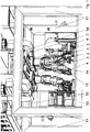
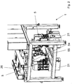
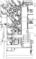
- FIG. 1 An embodiment of a mounting device according to the invention according to Fig. 1 .
- Fig. 2 and Fig. 3 for the fully automatic assembly of electromechanical, electromagnetic and / or electrohydraulic devices consists of a plurality of production cells 1, of which at least one has at least two linear axis systems 2, whose at least two carriages 3 each carry a multi-axis robot 4.
- the production cell 1 comprises a production frame 50 with four vertical feet 51, two upper horizontal cross members 52, two lower horizontal cross members 53, at least one upper side rail 54 and at least one lower side rail 55, wherein the linear axle 2 arranged on the underside of the upper longitudinal member 54 are.
- each designed as a linear motor drive unit 6 is integrated, so that the carriage 3 and thus mounted on the carriage 3 multi-axis robot 4 along the linear axis system 2 are movable to feed along the lower longitudinal member 55 arranged process modules 5.
- the linear axis systems 2 and the multi-axis robots 4 are set up such that the multi-axis robots 4 load or unload the process modules 5 with components and / or pre-assembly assemblies of the devices to be mounted and / or unload the assembled devices from a process module 5 and in a frame 14 which is disposed on the lower side member 55, put down.
- linear axis systems 2 and the multi-axis robots 4 in the in the Fig. 1 shown embodiment arranged so that the multi-axis robot 4, the components of the devices, pre-assembly and / or gripping the devices by means of grippers 15, apply and / or transport.
- the grippers 15 of the multi-axis robots are preferably set up so that they can grip, turn and transport a plurality of different components, preassembly assemblies or devices of a device family.
- the programmable logic controller 20 preferably causes in cooperation with the controllers 21 of the process modules 5 both a fully automatic assembly of the devices and a test of Devices in the process modules 5 as well as a fully automatic setup of the process modules 5 by controlling the movements of the multi-axis robot 4 and the linear axis systems 2 carrying them.
- the programmable logic controller 20 of the multi-axis robot 4 and the linear axis systems 2 and the controllers 21 of the process modules 5 programs that hold different program modules for controlling the mounting device in the setup process of the process modules 5 and in assembling the devices for different devices to be mounted.
- the different program modules for the controller 20 of the linear axis systems 2 and the multi-axis robot 4 on the one hand and the controllers 21 of the process modules 5 on the other hand for device-specific control of the mounting device are kept in a database.
Landscapes
- Engineering & Computer Science (AREA)
- Mechanical Engineering (AREA)
- Robotics (AREA)
- Physics & Mathematics (AREA)
- Automation & Control Theory (AREA)
- General Physics & Mathematics (AREA)
- Quality & Reliability (AREA)
- Manufacturing & Machinery (AREA)
- General Engineering & Computer Science (AREA)
- Chemical & Material Sciences (AREA)
- Combustion & Propulsion (AREA)
- Electromagnetism (AREA)
- Power Engineering (AREA)
- Manipulator (AREA)
- Automatic Assembly (AREA)
Applications Claiming Priority (2)
| Application Number | Priority Date | Filing Date | Title |
|---|---|---|---|
| DE102016007192.3A DE102016007192A1 (de) | 2016-06-14 | 2016-06-14 | Montagevorrichtung und Verfahren zur Steuerung der Montagevorrichtung |
| PCT/DE2017/100494 WO2017215708A1 (de) | 2016-06-14 | 2017-06-12 | Montagevorrichtung und verfahren zur steuerung der montagevorrichtung |
Publications (2)
| Publication Number | Publication Date |
|---|---|
| EP3448623A1 EP3448623A1 (de) | 2019-03-06 |
| EP3448623B1 true EP3448623B1 (de) | 2019-10-09 |
Family
ID=59315358
Family Applications (1)
| Application Number | Title | Priority Date | Filing Date |
|---|---|---|---|
| EP17737717.3A Active EP3448623B1 (de) | 2016-06-14 | 2017-06-12 | Montagevorrichtung, verfahren zur steuerung der montagevorrichtung und verfahren zum herstellen in einer montagevorrichtung |
Country Status (5)
| Country | Link |
|---|---|
| EP (1) | EP3448623B1 (enExample) |
| JP (1) | JP2019520224A (enExample) |
| CN (1) | CN109475988A (enExample) |
| DE (1) | DE102016007192A1 (enExample) |
| WO (1) | WO2017215708A1 (enExample) |
Cited By (1)
| Publication number | Priority date | Publication date | Assignee | Title |
|---|---|---|---|---|
| IT202100021320A1 (it) * | 2021-08-05 | 2023-02-05 | Idea Prototipi Srl | Cella di lavoro |
Families Citing this family (5)
| Publication number | Priority date | Publication date | Assignee | Title |
|---|---|---|---|---|
| IT201900006552A1 (it) | 2019-05-06 | 2020-11-06 | Ima Spa | Apparato e metodo per la gestione automatizzata di una camera di lavorazione ad atmosfera controllata. |
| WO2022011162A1 (en) * | 2020-07-08 | 2022-01-13 | Milara Incorporated | Flexible modular assembly system |
| CN112719838A (zh) * | 2020-12-30 | 2021-04-30 | 安徽航大智能科技有限公司 | 一种减速器自动翻转机 |
| CN115635297A (zh) * | 2022-10-20 | 2023-01-24 | 东莞市冠佳电子设备有限公司 | 360°旋转垂直组装设备 |
| CN117680946B (zh) * | 2023-12-28 | 2025-10-10 | 安徽万航轨道交通装备有限公司 | 一种轨道矿车轮对辅助装配装置 |
Family Cites Families (23)
| Publication number | Priority date | Publication date | Assignee | Title |
|---|---|---|---|---|
| US4890241A (en) * | 1987-10-26 | 1989-12-26 | Megamation Incorporated | Robotic system |
| JPH04210392A (ja) * | 1990-12-13 | 1992-07-31 | Mitsubishi Electric Corp | 産業用ロボット装置 |
| JP3311397B2 (ja) * | 1992-11-11 | 2002-08-05 | 三洋電機株式会社 | 部品装着ヘッド衝突回避方法及びそれを使用した部品装着装置 |
| JPH06179136A (ja) * | 1992-12-15 | 1994-06-28 | Mazda Motor Corp | 組付装置 |
| JPH08162797A (ja) * | 1994-12-08 | 1996-06-21 | Matsushita Electric Ind Co Ltd | 電子部品実装装置 |
| JP3230453B2 (ja) * | 1997-03-31 | 2001-11-19 | 日本鋼管株式会社 | 大型構造物の溶接ロボット装置 |
| US20020003997A1 (en) * | 2000-05-25 | 2002-01-10 | William Orinski | Manipulator/end effector head for robotic assembly |
| US20020185359A1 (en) * | 2001-06-06 | 2002-12-12 | Livingston John Scott | Robot having interlock mechanism |
| JP2003159679A (ja) * | 2001-11-27 | 2003-06-03 | Juki Corp | 複軸ロボット |
| JP4316336B2 (ja) * | 2003-09-26 | 2009-08-19 | パナソニック株式会社 | 部品実装ヘッド及び部品実装装置 |
| DE102004056493A1 (de) * | 2004-06-25 | 2006-01-12 | Dürr Systems GmbH | Beschichtungsanlage und zugehöriges Betriebsverfahren |
| JP4731903B2 (ja) * | 2004-12-24 | 2011-07-27 | パナソニック株式会社 | 部品実装用実装ヘッド、及び該実装ヘッドを備えた部品実装装置 |
| US8434414B2 (en) * | 2009-09-09 | 2013-05-07 | Rimrock Automation, Inc. | Multi-directional mobile robotic cell |
| JP5656804B2 (ja) * | 2011-11-07 | 2015-01-21 | 三菱電機株式会社 | 組立ロボット装置 |
| JP6039187B2 (ja) * | 2012-02-03 | 2016-12-07 | キヤノン株式会社 | 組立装置、把持ハンドおよび物品の組立方法 |
| JP6500328B2 (ja) * | 2014-02-06 | 2019-04-17 | 日産自動車株式会社 | 組み立て装置 |
| US9452500B2 (en) * | 2014-03-24 | 2016-09-27 | The Boeing Company | System and method for assembly manufacturing |
| JP2016058605A (ja) * | 2014-09-11 | 2016-04-21 | パナソニックIpマネジメント株式会社 | 部品実装方法 |
| TWI595958B (zh) * | 2014-09-30 | 2017-08-21 | 佳能股份有限公司 | 自動化組裝設備、自動化組裝系統及自動化組裝方法 |
| DE202015000787U1 (de) | 2014-10-05 | 2016-01-07 | Thomas Magnete Gmbh | Produktionsanlage und deren Teile |
| JP2015008339A (ja) * | 2014-10-17 | 2015-01-15 | 富士機械製造株式会社 | 製造作業機 |
| JP5970659B2 (ja) * | 2015-06-26 | 2016-08-17 | パナソニックIpマネジメント株式会社 | 電子部品実装システムおよび電子部品実装方法 |
| CN204748031U (zh) * | 2015-07-09 | 2015-11-11 | 徐州华恒机器人系统有限公司 | 龙门打磨、抛光、去毛刺机器人工作站 |
-
2016
- 2016-06-14 DE DE102016007192.3A patent/DE102016007192A1/de not_active Withdrawn
-
2017
- 2017-06-12 WO PCT/DE2017/100494 patent/WO2017215708A1/de not_active Ceased
- 2017-06-12 EP EP17737717.3A patent/EP3448623B1/de active Active
- 2017-06-12 CN CN201780037174.7A patent/CN109475988A/zh active Pending
- 2017-06-12 JP JP2018566311A patent/JP2019520224A/ja active Pending
Non-Patent Citations (1)
| Title |
|---|
| None * |
Cited By (2)
| Publication number | Priority date | Publication date | Assignee | Title |
|---|---|---|---|---|
| IT202100021320A1 (it) * | 2021-08-05 | 2023-02-05 | Idea Prototipi Srl | Cella di lavoro |
| WO2023012847A1 (en) * | 2021-08-05 | 2023-02-09 | Idea Prototipi S.R.L. | Work cell |
Also Published As
| Publication number | Publication date |
|---|---|
| DE102016007192A1 (de) | 2017-12-14 |
| JP2019520224A (ja) | 2019-07-18 |
| EP3448623A1 (de) | 2019-03-06 |
| CN109475988A (zh) | 2019-03-15 |
| WO2017215708A1 (de) | 2017-12-21 |
Similar Documents
| Publication | Publication Date | Title |
|---|---|---|
| EP3448623B1 (de) | Montagevorrichtung, verfahren zur steuerung der montagevorrichtung und verfahren zum herstellen in einer montagevorrichtung | |
| EP2792431B1 (de) | Bearbeitungsanlage für Flugzeugstrukturbauteile | |
| EP3535092B1 (de) | Honmaschine mit mehreren arbeitsstationen | |
| WO2015193331A1 (de) | Segmentierte aufnahmeplatte für ein werkstück | |
| DE102014104774A1 (de) | Ausschweiß-Spannvorrichtung | |
| DE202013012303U1 (de) | Honmaschine mit mehreren Arbeitsstationen und Rundtisch | |
| DE102009048863A1 (de) | Werkstück-Umsetz-Robotersystem | |
| EP1759808B1 (de) | Flexible Fertigungszelle für die Bearbeitung von Bauteilen, insbesondere von Fahrzeugkarosserien | |
| DE102012201728B4 (de) | Werkzeugmaschine mit palettenwechselvorrichtung | |
| EP1729917B1 (de) | Werkstückbearbeitungsverfahren und -vorrichtung für ein transfersystem mit mehrseitiger bearbeitung | |
| DE102022103409A1 (de) | Fertigungslinie | |
| DE60121941T2 (de) | Herstellungsverfahren und herstellungsanlage | |
| DE102014202257A1 (de) | Rekonfigurierbare Schnittstellenanordnung, anpassbarer Fliessband-Werkstückbearbeiter und Verfahren | |
| WO2012110176A1 (de) | Handhabungsmodul zum handhaben von kraftfahrzeugrädern | |
| EP3028806A1 (de) | Bearbeitungsvorrichtung | |
| EP3344417B1 (de) | Fertigungsmodul und verfahren zum betreiben des fertigungsmoduls | |
| DE102006000721A1 (de) | Handhabungssystem | |
| DE19853365A1 (de) | Verfahren und Vorrichtung zum Umformen | |
| EP3064417A1 (de) | Transportvorrichtung zum bewegen von werkstücken für den karosseriebau der kfz-industrie | |
| EP3717187B1 (de) | Stanzbearbeitungsstation und verfahren zur fixierung eines mit einer lackierung versehenen polymeren kfz-stossfängers während eines stanzvorganges | |
| EP2481528B1 (de) | Montagesystem und Positioniervorrichtung eines Montagesystems | |
| DE102022119044A1 (de) | Vorrichtung und Verfahren zur Fertigung von Produktvarianten | |
| DE102023002169A1 (de) | Vorrichtung zur Herstellung eines Leitungssatzes | |
| EP2829358A1 (de) | Werkstückwechsler für den automatischen Werkstück-oder Palettenwechsel bei einem Bearbeitungszentrum | |
| WO2018099515A2 (de) | VERFAHREN ZUM BONDEN GROßER MODULE UND BONDANORDNUNG |
Legal Events
| Date | Code | Title | Description |
|---|---|---|---|
| STAA | Information on the status of an ep patent application or granted ep patent |
Free format text: STATUS: UNKNOWN |
|
| STAA | Information on the status of an ep patent application or granted ep patent |
Free format text: STATUS: THE INTERNATIONAL PUBLICATION HAS BEEN MADE |
|
| PUAI | Public reference made under article 153(3) epc to a published international application that has entered the european phase |
Free format text: ORIGINAL CODE: 0009012 |
|
| STAA | Information on the status of an ep patent application or granted ep patent |
Free format text: STATUS: REQUEST FOR EXAMINATION WAS MADE |
|
| 17P | Request for examination filed |
Effective date: 20181126 |
|
| AK | Designated contracting states |
Kind code of ref document: A1 Designated state(s): AL AT BE BG CH CY CZ DE DK EE ES FI FR GB GR HR HU IE IS IT LI LT LU LV MC MK MT NL NO PL PT RO RS SE SI SK SM TR |
|
| AX | Request for extension of the european patent |
Extension state: BA ME |
|
| GRAP | Despatch of communication of intention to grant a patent |
Free format text: ORIGINAL CODE: EPIDOSNIGR1 |
|
| STAA | Information on the status of an ep patent application or granted ep patent |
Free format text: STATUS: GRANT OF PATENT IS INTENDED |
|
| DAV | Request for validation of the european patent (deleted) | ||
| DAX | Request for extension of the european patent (deleted) | ||
| INTG | Intention to grant announced |
Effective date: 20190621 |
|
| GRAS | Grant fee paid |
Free format text: ORIGINAL CODE: EPIDOSNIGR3 |
|
| GRAJ | Information related to disapproval of communication of intention to grant by the applicant or resumption of examination proceedings by the epo deleted |
Free format text: ORIGINAL CODE: EPIDOSDIGR1 |
|
| GRAL | Information related to payment of fee for publishing/printing deleted |
Free format text: ORIGINAL CODE: EPIDOSDIGR3 |
|
| STAA | Information on the status of an ep patent application or granted ep patent |
Free format text: STATUS: REQUEST FOR EXAMINATION WAS MADE |
|
| GRAR | Information related to intention to grant a patent recorded |
Free format text: ORIGINAL CODE: EPIDOSNIGR71 |
|
| STAA | Information on the status of an ep patent application or granted ep patent |
Free format text: STATUS: GRANT OF PATENT IS INTENDED |
|
| GRAA | (expected) grant |
Free format text: ORIGINAL CODE: 0009210 |
|
| STAA | Information on the status of an ep patent application or granted ep patent |
Free format text: STATUS: THE PATENT HAS BEEN GRANTED |
|
| INTC | Intention to grant announced (deleted) | ||
| AK | Designated contracting states |
Kind code of ref document: B1 Designated state(s): AL AT BE BG CH CY CZ DE DK EE ES FI FR GB GR HR HU IE IS IT LI LT LU LV MC MK MT NL NO PL PT RO RS SE SI SK SM TR |
|
| INTG | Intention to grant announced |
Effective date: 20190830 |
|
| REG | Reference to a national code |
Ref country code: GB Ref legal event code: FG4D Free format text: NOT ENGLISH |
|
| REG | Reference to a national code |
Ref country code: CH Ref legal event code: EP |
|
| REG | Reference to a national code |
Ref country code: IE Ref legal event code: FG4D Free format text: LANGUAGE OF EP DOCUMENT: GERMAN |
|
| REG | Reference to a national code |
Ref country code: DE Ref legal event code: R096 Ref document number: 502017002538 Country of ref document: DE |
|
| REG | Reference to a national code |
Ref country code: AT Ref legal event code: REF Ref document number: 1188224 Country of ref document: AT Kind code of ref document: T Effective date: 20191115 |
|
| REG | Reference to a national code |
Ref country code: CH Ref legal event code: NV Representative=s name: IPRIME RENTSCH KAELIN AG, CH |
|
| REG | Reference to a national code |
Ref country code: NL Ref legal event code: MP Effective date: 20191009 |
|
| REG | Reference to a national code |
Ref country code: LT Ref legal event code: MG4D |
|
| PG25 | Lapsed in a contracting state [announced via postgrant information from national office to epo] |
Ref country code: GR Free format text: LAPSE BECAUSE OF FAILURE TO SUBMIT A TRANSLATION OF THE DESCRIPTION OR TO PAY THE FEE WITHIN THE PRESCRIBED TIME-LIMIT Effective date: 20200110 Ref country code: FI Free format text: LAPSE BECAUSE OF FAILURE TO SUBMIT A TRANSLATION OF THE DESCRIPTION OR TO PAY THE FEE WITHIN THE PRESCRIBED TIME-LIMIT Effective date: 20191009 Ref country code: BG Free format text: LAPSE BECAUSE OF FAILURE TO SUBMIT A TRANSLATION OF THE DESCRIPTION OR TO PAY THE FEE WITHIN THE PRESCRIBED TIME-LIMIT Effective date: 20200109 Ref country code: LT Free format text: LAPSE BECAUSE OF FAILURE TO SUBMIT A TRANSLATION OF THE DESCRIPTION OR TO PAY THE FEE WITHIN THE PRESCRIBED TIME-LIMIT Effective date: 20191009 Ref country code: SE Free format text: LAPSE BECAUSE OF FAILURE TO SUBMIT A TRANSLATION OF THE DESCRIPTION OR TO PAY THE FEE WITHIN THE PRESCRIBED TIME-LIMIT Effective date: 20191009 Ref country code: LV Free format text: LAPSE BECAUSE OF FAILURE TO SUBMIT A TRANSLATION OF THE DESCRIPTION OR TO PAY THE FEE WITHIN THE PRESCRIBED TIME-LIMIT Effective date: 20191009 Ref country code: NL Free format text: LAPSE BECAUSE OF FAILURE TO SUBMIT A TRANSLATION OF THE DESCRIPTION OR TO PAY THE FEE WITHIN THE PRESCRIBED TIME-LIMIT Effective date: 20191009 Ref country code: PT Free format text: LAPSE BECAUSE OF FAILURE TO SUBMIT A TRANSLATION OF THE DESCRIPTION OR TO PAY THE FEE WITHIN THE PRESCRIBED TIME-LIMIT Effective date: 20200210 Ref country code: ES Free format text: LAPSE BECAUSE OF FAILURE TO SUBMIT A TRANSLATION OF THE DESCRIPTION OR TO PAY THE FEE WITHIN THE PRESCRIBED TIME-LIMIT Effective date: 20191009 Ref country code: NO Free format text: LAPSE BECAUSE OF FAILURE TO SUBMIT A TRANSLATION OF THE DESCRIPTION OR TO PAY THE FEE WITHIN THE PRESCRIBED TIME-LIMIT Effective date: 20200109 Ref country code: PL Free format text: LAPSE BECAUSE OF FAILURE TO SUBMIT A TRANSLATION OF THE DESCRIPTION OR TO PAY THE FEE WITHIN THE PRESCRIBED TIME-LIMIT Effective date: 20191009 |
|
| PG25 | Lapsed in a contracting state [announced via postgrant information from national office to epo] |
Ref country code: IS Free format text: LAPSE BECAUSE OF FAILURE TO SUBMIT A TRANSLATION OF THE DESCRIPTION OR TO PAY THE FEE WITHIN THE PRESCRIBED TIME-LIMIT Effective date: 20200224 Ref country code: HR Free format text: LAPSE BECAUSE OF FAILURE TO SUBMIT A TRANSLATION OF THE DESCRIPTION OR TO PAY THE FEE WITHIN THE PRESCRIBED TIME-LIMIT Effective date: 20191009 Ref country code: RS Free format text: LAPSE BECAUSE OF FAILURE TO SUBMIT A TRANSLATION OF THE DESCRIPTION OR TO PAY THE FEE WITHIN THE PRESCRIBED TIME-LIMIT Effective date: 20191009 |
|
| PG25 | Lapsed in a contracting state [announced via postgrant information from national office to epo] |
Ref country code: AL Free format text: LAPSE BECAUSE OF FAILURE TO SUBMIT A TRANSLATION OF THE DESCRIPTION OR TO PAY THE FEE WITHIN THE PRESCRIBED TIME-LIMIT Effective date: 20191009 |
|
| REG | Reference to a national code |
Ref country code: DE Ref legal event code: R097 Ref document number: 502017002538 Country of ref document: DE |
|
| PG2D | Information on lapse in contracting state deleted |
Ref country code: IS |
|
| PG25 | Lapsed in a contracting state [announced via postgrant information from national office to epo] |
Ref country code: EE Free format text: LAPSE BECAUSE OF FAILURE TO SUBMIT A TRANSLATION OF THE DESCRIPTION OR TO PAY THE FEE WITHIN THE PRESCRIBED TIME-LIMIT Effective date: 20191009 Ref country code: RO Free format text: LAPSE BECAUSE OF FAILURE TO SUBMIT A TRANSLATION OF THE DESCRIPTION OR TO PAY THE FEE WITHIN THE PRESCRIBED TIME-LIMIT Effective date: 20191009 Ref country code: CZ Free format text: LAPSE BECAUSE OF FAILURE TO SUBMIT A TRANSLATION OF THE DESCRIPTION OR TO PAY THE FEE WITHIN THE PRESCRIBED TIME-LIMIT Effective date: 20191009 Ref country code: DK Free format text: LAPSE BECAUSE OF FAILURE TO SUBMIT A TRANSLATION OF THE DESCRIPTION OR TO PAY THE FEE WITHIN THE PRESCRIBED TIME-LIMIT Effective date: 20191009 Ref country code: IS Free format text: LAPSE BECAUSE OF FAILURE TO SUBMIT A TRANSLATION OF THE DESCRIPTION OR TO PAY THE FEE WITHIN THE PRESCRIBED TIME-LIMIT Effective date: 20200209 |
|
| PGFP | Annual fee paid to national office [announced via postgrant information from national office to epo] |
Ref country code: CH Payment date: 20200618 Year of fee payment: 4 |
|
| PLBE | No opposition filed within time limit |
Free format text: ORIGINAL CODE: 0009261 |
|
| STAA | Information on the status of an ep patent application or granted ep patent |
Free format text: STATUS: NO OPPOSITION FILED WITHIN TIME LIMIT |
|
| PG25 | Lapsed in a contracting state [announced via postgrant information from national office to epo] |
Ref country code: SM Free format text: LAPSE BECAUSE OF FAILURE TO SUBMIT A TRANSLATION OF THE DESCRIPTION OR TO PAY THE FEE WITHIN THE PRESCRIBED TIME-LIMIT Effective date: 20191009 Ref country code: IT Free format text: LAPSE BECAUSE OF FAILURE TO SUBMIT A TRANSLATION OF THE DESCRIPTION OR TO PAY THE FEE WITHIN THE PRESCRIBED TIME-LIMIT Effective date: 20191009 Ref country code: SK Free format text: LAPSE BECAUSE OF FAILURE TO SUBMIT A TRANSLATION OF THE DESCRIPTION OR TO PAY THE FEE WITHIN THE PRESCRIBED TIME-LIMIT Effective date: 20191009 |
|
| 26N | No opposition filed |
Effective date: 20200710 |
|
| PGFP | Annual fee paid to national office [announced via postgrant information from national office to epo] |
Ref country code: DE Payment date: 20200709 Year of fee payment: 4 |
|
| REG | Reference to a national code |
Ref country code: CH Ref legal event code: PCOW Free format text: NEW ADDRESS: INNOMOTION PARK 3, 57562 HERDORF (DE) |
|
| PG25 | Lapsed in a contracting state [announced via postgrant information from national office to epo] |
Ref country code: SI Free format text: LAPSE BECAUSE OF FAILURE TO SUBMIT A TRANSLATION OF THE DESCRIPTION OR TO PAY THE FEE WITHIN THE PRESCRIBED TIME-LIMIT Effective date: 20191009 |
|
| PG25 | Lapsed in a contracting state [announced via postgrant information from national office to epo] |
Ref country code: MC Free format text: LAPSE BECAUSE OF FAILURE TO SUBMIT A TRANSLATION OF THE DESCRIPTION OR TO PAY THE FEE WITHIN THE PRESCRIBED TIME-LIMIT Effective date: 20191009 |
|
| PG25 | Lapsed in a contracting state [announced via postgrant information from national office to epo] |
Ref country code: LU Free format text: LAPSE BECAUSE OF NON-PAYMENT OF DUE FEES Effective date: 20200612 |
|
| REG | Reference to a national code |
Ref country code: BE Ref legal event code: MM Effective date: 20200630 |
|
| PG25 | Lapsed in a contracting state [announced via postgrant information from national office to epo] |
Ref country code: FR Free format text: LAPSE BECAUSE OF NON-PAYMENT OF DUE FEES Effective date: 20200630 Ref country code: IE Free format text: LAPSE BECAUSE OF NON-PAYMENT OF DUE FEES Effective date: 20200612 |
|
| PG25 | Lapsed in a contracting state [announced via postgrant information from national office to epo] |
Ref country code: BE Free format text: LAPSE BECAUSE OF NON-PAYMENT OF DUE FEES Effective date: 20200630 |
|
| REG | Reference to a national code |
Ref country code: DE Ref legal event code: R119 Ref document number: 502017002538 Country of ref document: DE |
|
| REG | Reference to a national code |
Ref country code: CH Ref legal event code: PL |
|
| GBPC | Gb: european patent ceased through non-payment of renewal fee |
Effective date: 20210612 |
|
| PG25 | Lapsed in a contracting state [announced via postgrant information from national office to epo] |
Ref country code: LI Free format text: LAPSE BECAUSE OF NON-PAYMENT OF DUE FEES Effective date: 20210630 Ref country code: GB Free format text: LAPSE BECAUSE OF NON-PAYMENT OF DUE FEES Effective date: 20210612 Ref country code: DE Free format text: LAPSE BECAUSE OF NON-PAYMENT OF DUE FEES Effective date: 20220101 Ref country code: CH Free format text: LAPSE BECAUSE OF NON-PAYMENT OF DUE FEES Effective date: 20210630 |
|
| PG25 | Lapsed in a contracting state [announced via postgrant information from national office to epo] |
Ref country code: TR Free format text: LAPSE BECAUSE OF FAILURE TO SUBMIT A TRANSLATION OF THE DESCRIPTION OR TO PAY THE FEE WITHIN THE PRESCRIBED TIME-LIMIT Effective date: 20191009 Ref country code: MT Free format text: LAPSE BECAUSE OF FAILURE TO SUBMIT A TRANSLATION OF THE DESCRIPTION OR TO PAY THE FEE WITHIN THE PRESCRIBED TIME-LIMIT Effective date: 20191009 Ref country code: CY Free format text: LAPSE BECAUSE OF FAILURE TO SUBMIT A TRANSLATION OF THE DESCRIPTION OR TO PAY THE FEE WITHIN THE PRESCRIBED TIME-LIMIT Effective date: 20191009 |
|
| PG25 | Lapsed in a contracting state [announced via postgrant information from national office to epo] |
Ref country code: MK Free format text: LAPSE BECAUSE OF FAILURE TO SUBMIT A TRANSLATION OF THE DESCRIPTION OR TO PAY THE FEE WITHIN THE PRESCRIBED TIME-LIMIT Effective date: 20191009 |
|
| REG | Reference to a national code |
Ref country code: AT Ref legal event code: MM01 Ref document number: 1188224 Country of ref document: AT Kind code of ref document: T Effective date: 20220612 |
|
| PG25 | Lapsed in a contracting state [announced via postgrant information from national office to epo] |
Ref country code: AT Free format text: LAPSE BECAUSE OF NON-PAYMENT OF DUE FEES Effective date: 20220612 |