EP3448304B1 - Interdentalreiniger - Google Patents
Interdentalreiniger Download PDFInfo
- Publication number
- EP3448304B1 EP3448304B1 EP17724315.1A EP17724315A EP3448304B1 EP 3448304 B1 EP3448304 B1 EP 3448304B1 EP 17724315 A EP17724315 A EP 17724315A EP 3448304 B1 EP3448304 B1 EP 3448304B1
- Authority
- EP
- European Patent Office
- Prior art keywords
- web
- interdental cleaner
- ribs
- rib
- handle part
- Prior art date
- Legal status (The legal status is an assumption and is not a legal conclusion. Google has not performed a legal analysis and makes no representation as to the accuracy of the status listed.)
- Active
Links
Images


Classifications
-
- A—HUMAN NECESSITIES
- A61—MEDICAL OR VETERINARY SCIENCE; HYGIENE
- A61C—DENTISTRY; APPARATUS OR METHODS FOR ORAL OR DENTAL HYGIENE
- A61C15/00—Devices for cleaning between the teeth
-
- A—HUMAN NECESSITIES
- A61—MEDICAL OR VETERINARY SCIENCE; HYGIENE
- A61C—DENTISTRY; APPARATUS OR METHODS FOR ORAL OR DENTAL HYGIENE
- A61C15/00—Devices for cleaning between the teeth
- A61C15/02—Toothpicks
-
- A—HUMAN NECESSITIES
- A46—BRUSHWARE
- A46B—BRUSHES
- A46B15/00—Other brushes; Brushes with additional arrangements
- A46B15/0055—Brushes combined with other articles normally separate from the brushing process, e.g. combs, razors, mirrors
- A46B15/0069—Brushes fitted with a interdental devices, e.g. toothpick
-
- A—HUMAN NECESSITIES
- A46—BRUSHWARE
- A46B—BRUSHES
- A46B5/00—Brush bodies; Handles integral with brushware
- A46B5/002—Brush bodies; Handles integral with brushware having articulations, joints or flexible portions
- A46B5/0054—Brush bodies; Handles integral with brushware having articulations, joints or flexible portions designed to allow relative positioning of the head to body
- A46B5/0062—Brush bodies; Handles integral with brushware having articulations, joints or flexible portions designed to allow relative positioning of the head to body being flexible or resilient during use
- A46B5/0066—Flexible resilience by elastic deformation of the material
-
- A—HUMAN NECESSITIES
- A46—BRUSHWARE
- A46B—BRUSHES
- A46B2200/00—Brushes characterized by their functions, uses or applications
- A46B2200/10—For human or animal care
- A46B2200/1066—Toothbrush for cleaning the teeth or dentures
- A46B2200/108—Inter-dental toothbrush, i.e. for cleaning interdental spaces specifically
-
- A—HUMAN NECESSITIES
- A46—BRUSHWARE
- A46B—BRUSHES
- A46B3/00—Brushes characterised by the way in which the bristles are fixed or joined in or on the brush body or carrier
- A46B3/005—Bristle carriers and bristles moulded as a unit
Definitions
- the invention relates to an interdental cleaner with a rod-shaped carrier made of plastic, which is provided in one end region with a cleaning part made of soft-elastic plastic, and with a handle part made of plastic, the carrier at its end facing the handle part in a connecting area via a web is integrally connected to the handle part.
- Such an interdental cleaner which is also referred to as a toothpick, is for example from the EP 0 932 371 known.
- the interdental cleaner shown there has a rod-shaped carrier made of a dimensionally stable plastic, at the rear end of which a handle part is molded in one piece via a connecting area.
- the carrier In its front end area facing away from the handle part, the carrier is provided with a soft-elastic covering which can be formed with radially projecting structural elements, for example in the form of molded fingers, lamellae or ribs, and forms a cleaning part.
- the user detects the interdental cleaner to clean the interdental spaces on the handle part and introduces the front end of the carrier and thus the cleaning part into the interdental space and moves the interdental cleaner back and forth.
- the cleaning effect essentially depends on the way in which the user guides the interdental cleaner within the interdental space.
- the orientation of the interdental cleaner is essentially determined by how the user arranges the handle part relative to the interdental space to be cleaned.
- the carrier has a certain elasticity and can be elastically deformed, if a special inclination of the cleaning section within the interdental space is necessary, this can only be achieved by the user aligning the entire interdental cleaner at an angle, which can be difficult to achieve in some cases ,
- Another interdental cleaner is out DE 10 2006 005 616 A1 known.
- the invention has for its object to provide an interdental cleaner of the type mentioned, which allows a more variable positioning of the cleaning part within the interdental space.
- connection area is designed as a joint, that the web is at least partially provided with a covering made of a soft, elastic plastic and that the web has at least one projecting web rib and that at least one rib is formed on the outside of the covering ,
- the ribs and / or the web ribs in the sense of the invention can be formed in different ways.
- the wall thickness or thickness of the casing and / or the web can be increased to form the ribs or web ribs.
- the invention is based on the basic idea of forming a joint in the connection area which connects the carrier to the handle part.
- the joint is conditioned by the geometric dimensions of the web in the connection area and / or by the choice of material.
- the soft-elastic plastic which is arranged in the connection area, acts as a spring and has a significant influence on the deformation properties of the interdental cleaner and the forces required for this.
- the deformation properties of the interdental cleaner can be predetermined in a desired manner by a suitable choice of the material for the soft-elastic plastic, for which a thermoplastic elastomer or silicone is used in particular.
- the material of the rod-shaped carrier and the geometry of the rod-shaped carrier, in particular in the region of the web also have an influence on the deformation properties of the interdental cleaner.
- the user can move the handle part relative to that in the interdental space Angle the inserted carrier with elastic deformation of the connection area, so that even areas of the tooth space that are difficult to reach can be cleaned in a simple manner.
- the carrier and the handle part are integrally connected to one another via the web.
- the carrier, the web and the handle part are injection-molded from a stable plastic, preferably as a monolithic component, and in a second process step, at least in the connection area to form the covering, the soft-elastic plastic is provided.
- the web is at least partially and in particular completely surrounded by the soft-elastic plastic, i.e. is encapsulated in the soft-elastic plastic.
- the connecting area has a preferably three-layer structure in cross section, in that the web arranged in the middle is covered on its top and bottom by soft, elastic plastic, so that a preferably complete covering is provided.
- connection area is achieved by the elastic deformation of the connection area or of the web and the casing and not by the relative adjustment between two independent components.
- at least one and preferably several protruding ribs are formed on the outside of the casing, which preferably extend essentially perpendicular to the longitudinal axis of the interdental cleaner.
- the ribs form reinforcing elements, areas in the foot region of the ribs and / or between the ribs being less rigid than the ribs, so that the stiffening ribs can ensure how the carrier deforms relative to the handle part.
- a plurality of ribs are preferably arranged in parallel next to one another, so that preferred bending axes or bending regions are established in the regions between adjacent ribs when a bending moment is applied between the carrier and the handle part.
- the web has at least one and preferably a plurality of projecting web ribs, which serve to ensure deformation of the carrier relative to the handle part about a predetermined axis which is essentially perpendicular to the longitudinal axis of the interdental cleaner.
- the web rib preferably extends essentially perpendicular to the longitudinal axis of the interdental cleaner and there are preferably a plurality of web ribs, in particular in parallel spaced apart. It can also be provided here that the web ribs are arranged only on one side of the web, alternatively it can be provided that on opposite sides of the web at least one web rib and preferably at least several web ribs are provided.
- the web has the said web ribs and the casing has the mentioned outer ribs.
- the web is preferably essentially plate-shaped and extends parallel or even in one plane with the likewise plate-shaped handle part.
- the web ribs are formed on two opposite sides of the web.
- the size and the height of the web ribs determine the bending strength of the connection area of the interdental cleaner.
- the web ribs all have a similar cross-sectional dimension.
- the height and thus the cross section of at least some web ribs are different.
- the rib or the ribs can be formed on only one side of the casing, alternatively it can be provided that at least one rib is provided on opposite sides of the casing.
- the web that connects the carrier and the handle part to one another preferably extends in the direction of the longitudinal axis of the interdental cleaner and can have a cross section that is constant over its length.
- the web has a cross section that widens in the direction of the handle part, and at the same time the thickness of the web can be constant over its length.
- the interdental cleaner In order to influence the deformation properties of the interdental cleaner in the area of the web or to reduce its rigidity, it can be provided in a development of the invention that at least one and preferably several openings are arranged in the web.
- the openings can be arranged at a distance in the direction of the longitudinal axis of the interdental cleaner and can extend transversely to the longitudinal axis in the manner of slots.
- the openings are preferably filled with the soft-elastic plastic of the covering, so that on the one hand there is an increased spring effect and on the other hand the soft-elastic plastic is positively connected to the carrier in the region of the web.
- the handle part can be provided with a support on a soft-elastic plastic, in particular a thermoplastic elastomer or a silicone.
- a soft-elastic plastic in particular a thermoplastic elastomer or a silicone.
- the same material is preferably used for this, which is also used as a soft-elastic plastic the wrapper is used.
- the support of the handle part is integrally connected to the soft-elastic plastic of the sheath, which simplifies manufacture and provides mutual support and support for the parts.
- the carrier is provided in particular at its front end with the cleaning part, which is provided, for example, in a known configuration as a sleeve-shaped coating with radially projecting structural elements such as integrally molded fingers and / or embedded bristles.
- the cleaning part also consists of a soft-elastic plastic and in particular of the same soft-elastic plastic from which the covering is made. It can be provided that the cleaning part is integrally connected to the soft-elastic plastic of the casing.
- the connection between the cleaning area and the casing can be provided via a connecting section made of soft-elastic plastic, which preferably extends in the direction of the longitudinal axis of the interdental cleaner.
- the connecting section is arranged in a channel and in particular an axial channel of the carrier and in particular is completely accommodated therein.
- a channel is preferably formed on opposite sides of the carrier.
- the cleaning part, the connecting section, the covering of the web and the coating of the handle part consist of the same soft-elastic material and are produced as a one-piece component in a single working step.
- a dimensionally stable plastic in particular polyprophylene, polyamide or polyethylene, is preferably used as the material for the carrier and / or the handle part.
- the material can be fiber-reinforced, for example by glass fibers, carbon fibers or natural fibers, in particular vegetable fibers.
- thermoplastic elastomer or silicone can be used as the soft-elastic plastic for the cleaning part and / or the covering and / or the support of the handle part.
- the web has a smooth, contourless surface on its underside and merges smoothly and continuously into the adjacent sections of the carrier and the handle part.
- the web On its opposite top, the web has a plurality of web ribs, in particular two web ribs which extend perpendicular to the longitudinal axis of the interdental cleaner and are spaced apart and parallel to one another.
- the web ribs are formed by forming groove-like depressions on the top of the web that extend perpendicular to the longitudinal axis of the interdental cleaner and are spaced apart and parallel to one another.
- a web rib is formed between two adjacent groove-like depressions.
- the web has a maximum thickness a in the range from 0.5 mm to 1.0 mm and in particular from 0.7 mm.
- the groove-like depressions have a depth b in the range from 0.1a to 0.3a and in particular 0.2a. This also corresponds to the height of the web ribs.
- the groove-like depressions preferably have a cross section in the form of a segment of a circle, the radius being in the range from 0.8 mm to 1.6 mm and preferably being 1.2 mm.
- connection area or the web is preferably completely encased by the covering made of the soft-elastic plastic, the covering being molded onto both the handle part and the carrier.
- the covering on the top of the web preferably has an approximately constant wall thickness and thus follows the contour of the web.
- several and in particular two, in the direction of the longitudinal axis L of the interdental cleaner at a distance from each other, parallel, protruding ribs are formed on the top of the casing, which are arranged exactly above the web ribs of the web.
- the wall thickness c or thickness of the covering should be in the range from 0.3 mm to 0.8 mm and in particular 0.5 mm to 0.6 mm.
- a plurality of groove-like depressions arranged at a distance and running perpendicular to the longitudinal axis of the interdental cleaner are also provided on the outside of the casing, a rib being formed between two adjacent groove-like depressions ,
- the groove-like depressions also have the shape of a circular segment in cross section a radius in the range of 0.5mm to 1.0mm and especially 0.7mm.
- the cover is preferably also provided on the underside of the web, but in the exemplary embodiment explained, the cover does not follow the shape, i.e. the smooth surface of the web, but the groove-like depressions and the ribs run completely around the web and are therefore also present on the underside of the web on the outside of the casing.
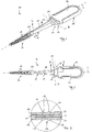
- FIGS. 1 and 2 show an interdental cleaner 10 according to the invention, which has a rod-shaped carrier 11 made of a dimensionally stable plastic, which tapers conically towards its front end, on the left as shown in the figures.
- Radially projecting structural elements in the form of molded fingers 14 are formed on the outer surface of the sleeve-shaped coating 13.
- the rod-shaped carrier 11 On the rear, according to the Figures 1 and 2 On the right end, the rod-shaped carrier 11 is connected to an essentially plate-shaped handle part 15 via a connecting region 16.
- the handle part 15 is provided with a support 21 made of a soft-elastic plastic, which can be the same material as the sleeve-shaped cover 13.
- the carrier 11 and the handle part 15 are integrally connected to each other via a web 19 extending axially in the direction of the longitudinal axis L of the interdental cleaner 10.
- the connecting region 16 forms a joint 23 about which the carrier 11 together with the cleaning part 12 can pivot about an axis D running perpendicular to the longitudinal axis L of the interdental cleaner 10, as indicated by the arrows S 1 and S 2 in Figure 1 is indicated.
- the pivoting is thus perpendicular to the plane of the drawing Figure 2 ,
- the carrier 11 and the handle member 15 are integrally connected to one another via the web 19.
- the web 19 has a smooth, contourless surface on its underside and merges smoothly and continuously into the adjacent sections of the carrier 11 and the handle part 15.
- the web 19 On its opposite upper side, the web 19 has two projecting web ribs 20, which extend perpendicularly to the longitudinal axis of the interdental cleaner 10, are spaced apart from one another and parallel to one another , wherein the sheath 24 is injection molded onto both the handle part 15 and the carrier 11.
- the casing 24 has on its outside two parallel, protruding ribs 17 which are arranged one behind the other in the direction of the longitudinal axis L of the interdental cleaner 10 and which, in the exemplary embodiment shown, run completely around the connection area and should be formed at least on the top and bottom thereof.
- the ribs 17 of the casing 24 lie exactly above the web ribs 20 of the web 19.
- the ribs 17 together with the web ribs 20 form reinforcement areas, so that the axis D is established in the area between the ribs 17 or between the web ribs 20.
- the cleaning part 12, the casing 24 and the support 21 of the handle part 15 are all made of the same soft-elastic material and are produced as a one-piece component by the cleaning part 12 on both its the upper side visible in the figures and also preferably on the opposite lower side is connected to the connecting region 16 via a rod-shaped connecting section 18.
- the connecting section 18 is arranged in an axial channel 22 of the carrier 11 and is flush with this surface.
- the connecting region 16 has an essentially frustoconical shape with a cross section widening in the direction of the longitudinal axis L towards the handle part 15.
- the web 19 follows this shape (s. 6 and 5 ), but it can also have a constant cross-section over its entire axial length (see 4 and 5 ).
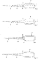
- the Figures 4 and 5 show only the component consisting of the dimensionally stable plastic in a first embodiment, which comprises the carrier 11, the web 19 and the handle part 15 and in a subsequent process step with the soft-elastic plastic to form the sleeve-shaped cover 13, the connecting section 18, the covering 24 and the pad 21 is encapsulated with soft-elastic plastic.
- the soft-elastic plastic completely surrounds the web 19 in the connection area 16 and encapsulates it.
- the external configuration of the connection area 16 corresponds to that of the exemplary embodiment according to FIGS Figures 1 and 2 ,
- the web 19 has a constant cross section over its axial length. On its top ( Figure 4 ) it is designed with the web ribs 20 running perpendicular to the longitudinal axis of the L. On its opposite Bottom ( Figure 5 ) there are no ribs, ie the web has a preferably flat lower surface.
- the sheath 24 formed in the connection area 16 can either have the above-mentioned ribs on both sides, but it can also be provided that the ribs only on one side of the sheath and preferably on the same Side on which the ribs of the web are also formed, or even to dispense with ribs completely on the covering, so that the covering then has a smooth surface on the outside.
- FIGS. 6 and 7 show a similar component as that Figures 4 and 5 and differ from them only in that the web 19 has a cross section which widens in the direction of the longitudinal axis L of the interdental cleaner 10 towards the handle part 15.
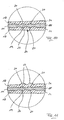
- Figure 8 shows a longitudinal section through an interdental cleaner 10, in which the connection area 16 is designed in an alternative manner.
- the connection area 16 is in Figure 9 shown in an enlarged view.
- the web 19 has both on its top and on its bottom two projecting web ribs 20 extending perpendicular to the longitudinal axis L of the interdental cleaner 10.
- the covering 24, which consists of the soft-elastic plastic, has a constant thickness in the illustrated embodiment, so that the surrounding ribs also on the outer surface of the covering 24 17 are formed.
- This embodiment thus has the web 19 with web ribs 17 on both sides and the casing 24 with ribs 17 on both sides.
- Figure 10 shows an alternative embodiment not according to the invention Figure 9 and differs from this in that the casing 24 has no outer ribs, but instead has a smooth outer surface on both sides, while the web 19 is provided with web ribs 20 on both sides.
- Figure 11 show an alternative to the design according to Figure 10 , here too the web 19 is provided on both sides with web ribs 20, but the covering 24 has ribs 17 on only one side and has a smooth surface on the opposite side.
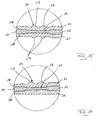
- FIG. 12 Another alternative embodiment is in Figure 12 shown.
- the web 19 has two web ribs 20 on its top, while it has a smooth, preferably flat surface on its underside.
- the covering 24 follows this shape, so that the covering 24 also has two ribs 17 on its upper side and has a smooth, preferably flat surface on its lower side.
- the web 19 has two web ribs 20 on its top and on its bottom a smooth, preferably flat surface.
- the sheath 24 has a smooth, preferably flat surface without ribs on both its top and bottom.
- Figure 14 shows the cross section in the connection area 16 with the web 19 according to a further alternative embodiment.
- the carrier 11 is connected to the handle part 15 via the web 19, the web 19 having a reduced overall height both with respect to the carrier 11 and with respect to the handle part 15 and having no web ribs but a smooth surface.
- the soft-elastic plastic forms the covering 24 and on the underside of the web 19 passes smoothly and continuously from the connecting section 18 into the surface of the covering 24 and from this smoothly and continuously into the support 21 of the handle part 15.
- the casing 24 is provided with two projecting ribs 17 which extend perpendicular to the longitudinal axis L of the interdental cleaner 10. This embodiment thus has the web 19 without web ribs and the casing 24 with ribs 17 on only one side.
- Figure 15 14 shows a modification of the embodiment according to FIG. 14, which differs from it only in that two protruding, circumferential ribs 17 of the type mentioned, which extend perpendicular to the longitudinal axis L of the interdental cleaner 10, are now formed on the outer surface of the casing 19.
- FIGS 16 and 17 show a further embodiment not according to the invention.
- This in Figure 16 shown component which comprises the rod-shaped carrier 11, the web 19 and the handle part 15, is characterized in that several webs 25 are provided in the longitudinal direction of the interdental cleaner, which are formed as linear slots and extend transversely to the longitudinal axis of the interdental cleaner in the web 19.
- the soft-elastic plastic which on the in Figure 16 Component shown is applied, passes through the web 19 at the openings 25, as in Figure 17 is shown. As a result, the soft-elastic plastic is held in a form-fitting manner in the region of the web 19.
- ribs are formed on the outside of the connecting region 18 in a manner already explained, the openings being offset in the longitudinal direction of the interdental cleaner to the ribs.
- the openings 25 in the web 19 can be provided in all the embodiments which have been explained above, i.e. both in configurations in which the web is provided with web ribs on both sides or only on one side or has no web ribs at all, and in configurations in which the covering is provided with ribs on both sides or only on one side or has no ribs at all.
- Figure 18 shows an enlarged sectional view accordingly Figure 3 , on the basis of which some dimensions of the web 19 and the casing 24 in the connection region 16 are explained.
- the web 19 has on its underside a smooth, contourless surface and goes smoothly and continuously into the neighboring Sections of the carrier 11 and the handle portion 15 over.
- the web 19 has two web ribs 20, which extend perpendicular to the longitudinal axis of the interdental cleaner 10 and are spaced apart and parallel to one another.
- the web ribs 20 are formed by extending on the top of the web 19 perpendicular to the longitudinal axis of the interdental cleaner 10, groove-like depressions 26 are arranged at a distance from one another and parallel to one another.
- a web rib 20 is formed in each case between two adjacent groove-like depressions 26.
- the web 19 has a maximum thickness a in the range from 0.5 mm to 1.0 mm and in particular from 0.7 mm.
- the groove-like depressions 26 have a depth b in the range from 0.1a to 0.3a and in particular 0.2a. This also corresponds to the height of the web ribs 20.
- the groove-like depressions 26 have a cross section in the form of a segment of a circle, the radius R 2 being in the range from 0.8 mm to 1.6 mm and preferably being 1.2 mm.
- the connecting area 16 or the web 19 is completely encased by the covering 24 made of the soft-elastic plastic, the covering 24 being molded onto both the handle part 15 and the carrier 11.
- the covering 24 on the top of the web 19 has an approximately constant wall thickness and thus follows the contour of the web 19. In this way there are also two on the top of the covering in the direction of the longitudinal axis L of the interdental cleaner 10 at a distance successive, parallel, projecting ribs 17 are formed, which are arranged exactly above the web ribs 20 of the web 19.
- the wall thickness c or thickness of the casing 24 should be in the range from 0.3 mm to 0.8 mm and in particular be 0.5 mm to 0.6 mm.
- the groove-like depressions 27 also have the shape of a circle segment with a radius R 1 in the range from 0.5 mm to 1.0 mm and in particular from 0.7 mm.
- the cover 24 is likewise provided on the underside of the web 19, but the cover 24 in the exemplary embodiment explained does not follow the shape, i.e. the smooth surface of the web 19, but the groove-like depressions 27 and the ribs 17 run completely around the web 19 and are therefore also present on the underside of the web 19 on the outside of the casing 24.
Landscapes
- Health & Medical Sciences (AREA)
- Dentistry (AREA)
- Epidemiology (AREA)
- Life Sciences & Earth Sciences (AREA)
- Animal Behavior & Ethology (AREA)
- General Health & Medical Sciences (AREA)
- Public Health (AREA)
- Veterinary Medicine (AREA)
- Brushes (AREA)
Description
- Die Erfindung betrifft einen Interdentalreiniger mit einem stabförmigen Träger aus Kunststoff, der in seinem einen Endbereich mit einem Reinigungsteil aus weich-elastischem Kunststoff versehen ist, und mit einem Handgriffteil aus Kunststoff, wobei der Träger an seinem dem Handgriffteil zugewandten Ende in einem Verbindungsbereich über einen Steg einstückig mit dem Handgriffteil verbunden ist.
- Ein derartiger Interdentalreiniger, der auch als Zahnstocher bezeichnet wird, ist beispielsweise aus der
EP 0 932 371 bekannt. Der dort gezeigte Interdentalreiniger besitzt einen stabförmigen Träger aus einem formstabilen Kunststoff, an dessen hinteren Ende über einen Verbindungsbereich ein Handgriffteil einstückig angeformt ist. In seinem vorderen, dem Handgriffteil abgewandten Endbereich ist der Träger mit einem weich-elastischen Überzug versehen, der mit radial hervorstehenden Strukturelementen beispielsweise in Form von angeformten Fingern, Lamellen oder Rippen ausgebildet sein kann und ein Reinigungsteil bildet. Zur Reinigung der Zahnzwischenräume erfasst der Nutzer den Interdentalreiniger an dem Handgriffteil und führt das vordere Ende des Trägers und somit das Reinigungsteil in den Zahnzwischenraum ein und bewegt den Interdentalreiniger hin und her. - Es hat sich gezeigt, dass die Reinigungswirkung wesentlich von der Art und Weise abhängt, wie der Nutzer den Interdentalreiniger innerhalb des Zahnzwischenraumes führt. Dabei ist die Ausrichtung des Interdentalreinigers im wesentlichen dadurch bestimmt, wie der Benutzer das Handgriffteil relativ zu dem zu reinigenden Zahnzwischenraum anordnet. Zwar besitzt der Träger eine gewisse Elastizität und kann elastisch verformt werden, falls eine besondere Schrägstellung des Reinigungsabschnittes innerhalb des Zahnzwischenraums notwendig ist, lässt sich diese jedoch nur erreichen, indem der Benutzer den gesamten Interdentalreiniger entsprechend schräg ausrichtet, was in manchen Fällen schwierig zu erreichen ist.
- Ein weiterer Interdentalreiniger ist aus
DE 10 2006 005 616 A1 bekannt. - Der Erfindung liegt die Aufgabe zugrunde, einen Interdentalreiniger der genannten Art zu schaffen, der eine variablere Positionierung des Reinigungsteils innerhalb des Zahnzwischenraums ermöglicht.
- Diese Aufgabe wird erfindungsgemäß durch einen Interdentalreiniger mit den Merkmalen des Anspruchs 1 gelöst. Dabei ist vorgesehen, dass der Verbindungsbereich als Gelenk ausgebildet ist, dass der Steg zumindest teilweise mit einer Umhüllung aus einem weich elastischen Kunststoff versehen ist und dass der Steg zumindest eine hervorstehende Steg-Rippe aufweist und dass auf der Außenseite der Umhüllung zumindest eine Rippe ausgebildet ist.
- Die Rippen und/oder die Stegrippen im Sinne der Erfindung können auf unterschiedliche Weise gebildet werden. Einerseits ist es möglich, auf der Außenseite der Umhüllung und/oder auf der Außenseite des Steges senkrecht zur Längsachse des Interdentalreinigers verlaufende, parallel auf Abstand nebeneinander angeordnete nutartige Vertiefungen einzubringen, so dass zwischen zwei benachbarten Vertiefungen jeweils eine Rippe bzw. eine Stegrippe gebildet ist. Andererseits kann die Wandstärke bzw. Dicke der Umhüllung und/oder des Steges zur Bildung der Rippen bzw. Stegrippen erhöht werden.
- Die Erfindung geht von der Grundüberlegung aus, in dem Verbindungsbereich, der den Träger mit dem Handgriffteil verbindet, ein Gelenk auszubilden. Dabei ist das Gelenk einerseits durch die im Verbindungsbereich gegebenen geometrischen Abmessungen des Stegs und/oder durch die Materialwahl bedingt. Insbesondere der weich-elastische Kunststoff, der in dem Verbindungsbereich angeordnet ist, wirkt als Feder und hat wesentlichen Einfluss auf die Verformungseigenschaften des Interdentalreinigers und die dazu notwendigen Kräfte. Durch geeignete Wahl des Materials für den weich-elastischen Kunststoff, für den insbesondere ein thermoplastisches Elastomer oder Silikon verwendet wird, können die Verformungseigenschaften des Interdentalreinigers in gewünschter Weise vorgegeben werden. Auch das Material des stabförmigen Trägers und die Geometrie des stabförmigen Trägers insbesondere im Bereich des Stegs haben einen Einfluss auf die Verformungseigenschaften des Interdentalreinigers.
- Bei Benutzung des Interdentalreinigers kann der Benutzer das Handgriffteil relativ zu dem in dem Zahnzwischenraum eingeführten Träger unter elastischer Verformung des Verbindungsbereichs abwinkeln, so dass sich auch schwierig zu erreichende Bereiche des Zahnzwischenraums in einfacher Weise reinigen lassen.
- Für die Handhabung des Interdentalreinigers hat es sich als vorteilhaft erwiesen, eine gegenseitige Verstellung zwischen dem Träger und dem Handgriffteil nur um eine Achse vorzusehen, die vorzugsweise senkrecht zur Längsachse des Interdentalreinigers verläuft. Dies kann durch ein Gelenk nach Art eines Scharniergelenks erreicht werden.
- Zur Aufbringung größerer Kräfte durch den Benutzer und zur Vermeidung einer übermäßigen Verformung des Verbindungsbereiches ist vorgesehen, dass der Träger und das Handgriffteil über den Steg einstückig miteinander verbunden sind. Dabei werden der Träger, der Steg und das Handgriffteil in einem ersten Verfahrensschritt aus einem stabilen Kunststoff vorzugsweise als monolithisches Bauteil gespritzt und in einem zweiten Verfahrensschritt zumindest in dem Verbindungsbereich zur Bildung der Umhüllung mit dem weich-elastischen Kunststoff versehen. Dabei kann vorgesehen sein, dass der Steg zumindest teilweise und insbesondere vollständig von dem weich-elastischen Kunststoff umgeben, d.h. in den weich-elastischen Kunststoff eingekapselt ist.
- Aufgrund des Vorhandenseins des Steges besitzt der Verbindungsbereich einen im Querschnitt vorzugsweise dreischichtigen Aufbau, indem der in der Mitte angeordnete Steg auf seiner Oberseite und seiner Unterseite von weich elastischem Kunststoff überzogen ist, so dass eine vorzugsweise vollständige Umhüllung gegeben ist.
- Das Gelenk des Verbindungsbereichs wird durch die elastische Verformung des Verbindungsbereichs bzw. des Steges und der Umhüllung und nicht durch die relative Verstellung zwischen zwei unabhängigen Bauteilen erreicht. Um die Verformung des Verbindungsbereiches in gewünschter Weise in einer vorbestimmten Richtung zu erzielen, ist gemäß der Erfindung vorgesehen, dass auf der Außenseite der Umhüllung zumindest eine und vorzugsweise mehrere hervorstehende Rippen ausgebildet sind, die sich vorzugsweise im wesentlichen senkrecht zur Längsachse des Interdentalreinigers erstrecken. Die Rippen bilden Verstärkungselemente, wobei im Fußbereich der Rippen und/oder zwischen den Rippen Bereiche gegeben sind, die im Vergleich zu den Rippen eine geringere Biegesteifigkeit besitzen, so dass durch die aussteifenden Rippen sichergestellt werden kann, wie sich der Träger relativ zum Handgriffteil verformt.
- Vorzugsweise sind mehrere Rippen insbesondere parallel nebeneinander angeordnet, so dass sich in den Bereichen zwischen benachbarten Rippen bevorzugte Biegeachsen oder Biegebereiche bei Aufbringung eines Biegemomentes zwischen dem Träger und dem Handgriffteil einstellen.
- Zusätzlich zu den Rippen der Umhüllung ist erfindungsgemäß vorgesehen, dass der Steg zumindest eine und vorzugsweise mehrere hervorstehende Steg-Rippen aufweist, die dazu dienen, eine Verformung des Trägers relativ zum Handgriffteil um eine vorbestimmte, im wesentlichen senkrecht zur Längsachse des Interdentalreinigers verlaufende Achse sicherzustellen. Zu diesem Zweck erstreckt sich die Steg-Rippe vorzugsweise im wesentlichen senkrecht zur Längsachse des Interdentalreinigers und es sind vorzugsweise mehrere Steg-Rippen insbesondere parallel auf Abstand nebeneinander angeordnet. Auch hierbei kann vorgesehen sein, dass die Steg-Rippen nur auf einer Seite des Steges angeordnet sind, alternativ kann vorgesehen sein, dass auf entgegengesetzten Seiten des Steges jeweils zumindest eine Steg-Rippe und vorzugsweise jeweils zumindest mehrere Steg-Rippen vorgesehen sein.
- Erfindungsgemäß besitzt der Steg die genannten Steg-Rippen und die Umhüllung die genannten äußeren Rippen. Vorzugsweise ist der Steg im wesentlichen plattenförmig ausgestaltet und erstreckt sich parallel oder sogar in einer Ebene mit den ebenfalls plattenförmig ausgestalteten Handgriffteil. In einer möglichen Ausgestaltung kann es vorgesehen sein, dass die Steg-Rippen auf zwei entgegengesetzten Seiten des Steges ausgebildet sind. Alternativ dazu ist es möglich, dass die Steg-Rippen nur auf einer Seite des Steges ausgebildet sind. In diesem Fall kann die den Steg-Rippen abgewandte andere Seite des Steges eben und insbesondere unstrukturiert ausgebildet sein.
- Die Größe und die Höhe der Steg-Rippen bestimmt die Biegefestigkeit des Verbindungsbereichs des Interdentalreinigers. In einer möglichen Ausgestaltung kann vorgesehen sein, dass die Steg-Rippen alle eine gleichartige Querschnittsabmessung aufweisen. Alternativ kann vorgesehen sein, dass die Höhe und damit der Querschnitt zumindest einiger Steg-Rippen unterschiedlich ist.
- Die Rippe oder die Rippen können auf nur einer Seite der Umhüllung ausgebildet sein, alternativ kann vorgesehen sein, dass auf entgegengesetzten Seiten der Umhüllung jeweils zumindest eine Rippe vorgesehen ist.
- Der Steg, der den Träger und das Handgriffteil miteinander verbindet, erstreckt sich vorzugsweise in Richtung der Längsachse des Interdentalreinigers und kann einen über seine Länge konstanten Querschnitt aufweisen. In bevorzugter Ausgestaltung der Erfindung ist vorgesehen, dass der Steg ein sich in Richtung des Handgriffteils verbreitenden Querschnitt aufweist, wobei gleichzeitig die Dicke des Stegs über seine Länge konstant sein kann.
- Um die Verformungseigenschaften des Interdentalreinigers im Bereich des Steges zu beeinflussen oder um dessen Steifigkeit zu verringern, kann in Weiterbildung der Erfindung vorgesehen sein, dass in dem Steg zumindest eine und vorzugsweise mehrere Durchbrechungen angeordnet sind. Die Durchbrechungen können in Richtung der Längsachse des Interdentalreinigers auf Abstand angeordnet sein und sich nach Art von Schlitzen quer zur Längsachse erstrecken. Vorzugsweise sind die Durchbrechungen mit dem weich-elastischen Kunststoff der Umhüllung gefüllt, so dass einerseits eine erhöhte Federwirkung gegeben ist und andererseits der weich-elastische Kunststoff formschlüssig mit dem Träger im Bereich des Steges verbunden ist.
- Damit der Benutzer das Handgriffteil sicher erfassen kann und von diesem nicht abrutscht, kann das Handgriffteil mit einer Auflage auf einem weich-elastischen Kunststoff, insbesondere einem thermoplastischen Elastomer oder einem Silikon versehen sein. Vorzugsweise wird dazu das gleiche Material verwendet, das auch als weich-elastischer Kunststoff der Umhüllung verwendet wird. Dabei kann vorgesehen sein, dass die Auflage des Handgriffteils mit dem weich-elastischen Kunststoff der Umhüllung einstückig verbunden ist, wodurch die Herstellung vereinfacht und eine gegenseitige Abstützung und Halterung der Teile gegeben ist.
- Der Träger ist insbesondere an seinem vorderen Ende mit dem Reinigungsteil versehen, das beispielsweise in bekannter Ausgestaltung als hülsenförmiger Überzug mit radial hervorstehenden Strukturelementen wie einstückig angeformten Fingern und/oder eingebetteten Borsten versehen ist. Das Reinigungsteil besteht ebenfalls aus einem weich-elastischen Kunststoff und insbesondere aus dem gleichen weich-elastischen Kunststoff, aus dem auch die Umhüllung besteht. Dabei kann vorgesehen sein, dass das Reinigungsteil mit dem weich-elastischen Kunststoff der Umhüllung einstückig verbunden ist. Die Verbindung zwischen dem Reinigungsbereich und der Umhüllung kann über einen Verbindungsabschnitt aus weich-elastischem Kunststoff gegeben sein, der sich vorzugsweise in Richtung der Längsachse des Interdentalreinigers erstreckt. Dabei kann vorgesehen sein, dass der Verbindungsabschnitt in einem Kanal und insbesondere einem Axialkanal des Trägers angeordnet und insbesondere vollständig in diesem aufgenommen ist. Vorzugsweise ist auf entgegengesetzten Seiten des Trägers jeweils ein Kanal ausgebildet.
- In einer weiteren möglichen Ausgestaltung der Erfindung kann vorgesehen sein, dass das Reinigungsteil, der Verbindungsabschnitt, die Umhüllung des Stegs und die Beschichtung des Handgriffteils aus dem gleichen weich-elastischen Material bestehen und in einem einzigen Arbeitsschritt als einstückiges Bauteil hergestellt sind.
- Als Material für den Träger und/oder das Handgriffteil findet vorzugsweise ein formstabiler Kunststoff, insbesondere Polyprophylen, Polyamid oder Polyethylen Verwendung. Das Material kann faserverstärkt sein, beispielsweise durch Glasfasern, Karbonfasern oder natürliche Fasern, insbesondere Pflanzenfasern.
- Als weich-elastischer Kunststoff für das Reinigungsteil und/oder die Umhüllung und/oder die Auflage des Handgriffteils kann ein thermoplastisches Elastomer oder Silikon Verwendung finden.
- Im folgenden werden einige Abmessungen des Steges und der Umhüllung im Verbindungsbereich erläutert.
- In einer möglichen Ausführungsform besitzt der Steg auf seiner Unterseite eine glatte, konturlose Oberfläche und geht glatt und stufenlos in die benachbarten Abschnitte des Trägers und des Handgriffteils über. Auf seiner entgegengesetzten Oberseite besitzt der Steg mehrere und insbesondere zwei sich senkrecht zur Längsachse des Interdentalreinigers erstreckende, auf Abstand voneinander und parallel zueinander angeordnete Stegrippen. Die Stegrippen sind gebildet, indem auf der Oberseite des Steges sich senkrecht zur Längsachse des Interdentalreinigers erstreckende, auf Abstand voneinander und parallel zueinander angeordnete nutartige Vertiefungen ausgebildet sind. Zwischen zwei benachbarten nutartigen Vertiefungen ist jeweils eine Stegrippe gebildet.
- Der Steg besitzt eine maximale Dicke a im Bereich von 0,5mm bis 1,0mm und insbesondere von 0,7mm. Die nutartigen Vertiefungen besitzen eine Tiefe b im Bereich von 0,1a bis 0,3a und insbesondere 0,2a. Dies entspricht auch der Höhe der Stegrippen.
- Vorzugweise besitzen die nutartigen Vertiefungen einen Querschnitt in Form eines Kreissegments, wobei der Radius im Bereich von 0,8mm bis 1,6mm liegt und vorzugsweise 1,2mm beträgt.
- Der Verbindungsbereich bzw. der Steg ist vorzugsweise vollständig von der Umhüllung aus dem weich-elastischen Kunststoff ummantelt, wobei die Umhüllung sowohl an das Handgriffteil als auch an den Träger angespritzt ist.
- Vorzugsweise besitzt die Umhüllung auf der Oberseite des Steges eine annähernd konstante Wandstärke und folgt somit der Kontur des Steges. Auf diese Weise sind auf der Oberseite der Umhüllung ebenfalls mehrere und insbesondere zwei in Richtung der Längsachse L des Interdentalreinigers auf Abstand hintereinander liegende, parallel angeordnete, hervorstehende Rippen gebildet, die genau über den Stegrippen des Steges angeordnet sind. Die Wandstärke c bzw. Dicke der Umhüllung sollte im Bereich von 0,3mm bis 0,8mm liegen und insbesondere 0,5mm bis 0,6mm betragen.
- Da die Formgebung auf der Außenseite der Umhüllung der Formgebung auf der Oberseite des Steges folgt, sind auch auf der Außenseite der Umhüllung mehrere senkrecht zur Längsachse des Interdentalreinigers verlaufende, auf Abstand angeordnete nutartige Vertiefungen vorgesehen, wobei zwischen zwei benachbarten nutartigen Vertiefungen jeweils eine Rippe gebildet ist. Auch die nutartigen Vertiefungen besitzen im Querschnitt die Form eines Kreissegmentes mit einem Radius im Bereich von 0,5mm bis 1,0mm und insbesondere von 0,7mm.
- Auf der Unterseite des Steges ist vorzugsweise ebenfalls die Umhüllung vorgesehen, jedoch folgt die Umhüllung im erläuterten Ausführungsbeispiel in diesem Bereich nicht der Formgebung, d.h. der glatten Oberfläche des Steges, sondern die nutartigen Vertiefungen und die Rippen laufen vollständig um den Steg herum und sind somit auch auf der Unterseite des Steges auf der Außenseite der Umhüllung vorhanden.
- Weitere Einzelheiten und Merkmale der Erfindung sind aus der folgenden Beschreibung von Ausführungsbeispielen unter Bezugnahme auf die Zeichnung ersichtlich. Es zeigen:
-
Fig. 1 Eine perspektivische Ansicht eines erfindungsgemäßen Interdentalreinigers, -
Fig. 2 eine Aufsicht auf den Interdentalreiniger gemäßFigur 1 , -
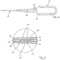
Fig. 3 den Schnitt III-III inFigur 2 -
Fig. 4 dem stabförmigen Träger, den Steg und das Handgriffteil als einstückiges Bauteil in einer möglichen Ausführungsform in Aufsicht, -
Fig. 5 eine Unteransicht des Bauteils gemäßFig. 4 , -
Fig. 6 den stabförmigen Träger, den Steg und das Handgriffteil als einstückiges Bauteil in einer alternativen Ausführungsform, -
Fig. 7 eine Unteransicht des Bauteils gemäßFig. 6 , -
Fig. 8 einen Längsschnitt durch den Interdentalreiniger gemäß einer weiteren Ausführungsform, -
Fig. 9 das Detail IX ausFigur 8 , -
Fig. 10 eineFigur 9 entsprechende Schnittdarstellung einer nicht erfindungsgemäßen alternativen Ausführungsform, -
Fig. 11 eineFigur 9 entsprechende Schnittdarstellung einer weiteren alternativen Ausführungsform, -
Fig. 12 eineFigur 9 entsprechende Schnittdarstellung einer weiteren alternativen Ausführungsform, -
Fig. 13 eineFigur 9 entsprechende Schnittdarstellung einer nicht erfindungsgemäßen weiteren alternativen Ausführungsform, -
Fig. 14 eineFigur 9 entsprechende Schnittdarstellung einer weiteren alternativen Ausführungsform, -
Fig. 15 eineFigur 9 entsprechende Schnittdarstellung einer weiteren alternativen Ausführungsform, -
Fig. 16 den stabförmigen Träger, den Steg und das Handgriffteil als einstückiges Bauteil in einer weiteren nicht erfindungsgemäßen Ausführungsform, -
Fig. 17 einen auszugsweise Längsschnitt durch das Bauteil gemäßFig. 11 mit aufgebrachter Umhüllung und -
Fig. 18 eine vergrößerte Schnittdarstellung entsprechendFig. 3 - Die
Figuren 1 und 2 zeigen einen erfindungsgemäßen Interdentalreiniger 10, der einen stabförmigen Träger 11 aus einem formstabilen Kunststoff aufweist, der sich zu seinem vorderen, gemäß den Figuren linken Ende hin konisch verjüngt. In seinem vorderen, den gemäß den Figuren linken Endbereich ist auf den Träger 11 ein Reinigungsteil 12 in Form eines hülsenförmigen Überzugs 13 aus einem weich-elastischen Kunststoff, beispielsweise einem thermoplastischen Elastomer oder Silikon aufgebracht und insbesondere aufgespritzt. Auf der Außenoberfläche des hülsenförmigen Überzugs 13 sind radial hervorstehende Strukturelemente in Form von angeformten Fingern 14 ausgebildet. - An dem hinteren, gemäß den
Figuren 1 und 2 rechten Ende ist der stabförmige Träger 11 über einen Verbindungsbereich 16 mit einem im wesentlichen plattenförmigen Handgriffteil 15 verbunden. Das Handgriffteil 15 ist mit einer Auflage 21 aus einem weich-elastischen Kunststoff versehen, bei dem es sich um das gleiche Material wie bei dem hülsenförmigen Überzug 13 handeln kann. - Wie der
Fig. 3 zu entnehmen ist, sind der Träger 11 und das Handgriffteil 15 über einen sich axial in Richtung der Längsachse L des Interdentalreinigers 10 erstreckenden Steg 19 einstückig miteinander verbunden sind. - Der Verbindungsbereich 16 bildet ein Gelenk 23, um das der Träger 11 zusammen mit dem Reinigungsteil 12 um eine senkrecht zur Längsachse L des Interdentalreinigers 10 verlaufende Achse D schwenken kann, wie es durch die Pfeile S1 und S2 in
Figur 1 angedeutet ist. Die Schwenkung erfolgt somit senkrecht zur Zeichenebene gemäßFigur 2 . - Wie
Figur 3 zeigt, sind der Träger 11 und das Handgriffteil 15 über den Steg 19 einstückig miteinander verbunden. Der Steg 19 besitzt auf seiner Unterseite eine glatte, konturenlose Oberfläche und geht glatt und stufenlos in die benachbarten Abschnitte des Trägers 11 und des Handgriffteils 15 über. Auf seiner entgegengesetzten Oberseite besitzt der Steg 19 zwei sich senkrecht zur Längsachse des Interdentalreinigers 10 erstreckende, auf Abstand voneinander und parallel zueinander angeordnete, hervorstehende Stegrippen 20. Der Verbindungsbereich 16 bzw. der Steg 19 ist vollständig von einer Umhüllung 24 aus dem weich elastischen Kunststoff ummantelt, wobei die Umhüllung 24 sowohl an das Handgriffteil 15 als auch an den Träger 11 angespritzt ist. - Die Umhüllung 24 besitzt auf ihrer Außenseite zwei in Richtung der Längsachse L des Interdentalreinigers 10 auf Abstand hintereinander liegende, parallel angeordnete, hervorstehende Rippen 17, die beim dargestellten Ausführungsbeispiel vollständig um den Verbindungsbereich umlaufen und zumindest auf dessen Oberseite und dessen Unterseite ausgebildet sein sollten. Die Rippen 17 der Umhüllung 24 liegen genau über den Stegrippen 20 des Stegs 19. Die Rippen 17 bilden zusammen mit den Steg-Rippen 20 Verstärkungsbereiche, so dass die Achse D sich im Bereich zwischen den Rippen 17 bzw. zwischen den Stegrippen 20 einstellt.
- Das Reinigungsteil 12, die Umhüllung 24 und die Auflage 21 des Handgriffteils 15 bestehen alle aus dem gleichen weich-elastischen Material und sind als einstückiges Bauteil hergestellt, indem das Reinigungsteil 12 sowohl auf seiner in den Figuren sichtbaren Oberseite als auch vorzugsweise auf der entgegengesetzten Unterseite jeweils über einen stabförmigen Verbindungsabschnitt 18 mit dem Verbindungsbereich 16 verbunden ist. Wie insbesondere
Figur 1 zeigt, ist der Verbindungsabschnitt 18 in einem Axialkanal 22 des Trägers 11 angeordnet und schließt mit diesem oberflächlich bündig ab. - Der Verbindungsbereich 16 besitzt eine im wesentlichen kegelstumpfartige Form mit einem sich in Richtung der Längsachse L zum Handgriffteil 15 hin verbreiternden Querschnitt. Der Steg 19 folgt dieser Formgebung (s.
Fig. 6 und 5 ), er kann aber auch über seine gesamte axiale Länge einen konstanten Querschnitt aufweisen (s.Fig. 4 und 5 ). - Die
Figuren 4 und 5 zeigen nur das aus dem formstabilen Kunststoff bestehende Bauteil in einer 1. Ausführungsform, das den Träger 11, den Steg 19 und das Handgriffteil 15 umfasst und in einem nachfolgenden Verfahrensschritt mit dem weich-elastischen Kunststoff zur Bildung des hülsenförmigen Überzugs 13, des Verbindungsabschnitts 18, der Umhüllung 24 und der Auflage 21 mit weich-elastischem Kunststoff umspritzt wird. Dabei umgibt der weich-elastische Kunststoff in dem Verbindungsbereich 16 den Steg 19 vollständig und kapselt diesen ein. Die äußere Ausgestaltung des Verbindungsbereichs 16 entspricht derjenigen des Ausführungsbeispiels gemäß denFiguren 1 und 2 . - Bei dem in den
Figuren 4 und 5 dargestellten Ausführungsbeispiel besitzt der Steg 19 über seine axiale Länge einen konstanten Querschnitt. Auf seiner Oberseite (Figur 4 ) ist er mit den senkrecht zur Längsachse des L verlaufenden Steg-Rippen 20 ausgestaltet. Auf seiner entgegengesetzten Unterseite (Figur 5 ) sind keine Rippen vorgesehen, d.h. der Steg besitzt eine vorzugsweise ebene untere Oberfläche. - Wenn das in den
Figuren 4 und 5 dargestellte Bauteil mit dem weich-elastischen Kunststoff umspritzt wird, kann die in dem Verbindungsbereich 16 ausgebildete Umhüllung 24 wahlweise entweder auf beiden Seiten die genannten Rippen aufweisen, es kann jedoch auch vorgesehen sein, die Rippen nur auf einer Seite der Umhüllung und vorzugsweise auf der gleichen Seite, auf der auch die Rippen des Steges ausgebildet sind, vorzusehen oder sogar an der Umhüllung auf Rippen vollständig zu verzichten, so dass die Umhüllung dann eine außenseitige glatte Oberfläche besitzt. - Die
Figuren 6 und 7 zeigen ein gleichartiges Bauteil wie dieFigur 4 und 5 und unterscheiden sich von diesen lediglich dadurch, dass der Steg 19 einen sich in Richtung der Längsachse L des Interdentalreinigers 10 zum Handgriffteil 15 hin erweiternden Querschnitt besitzt. - Auch das in den
Figuren 6 und 7 dargestellte Bauteil wird in einem nachfolgenden Verfahrensschritt in genannter Weise mit dem weich-elastischen Kunststoff umgeben, wobei die oben stehenden Ausführungen zu der Anordnung der Rippen auch hier entsprechend gelten. -
Figur 8 zeigt einen Längsschnitt durch einen Interdentalreiniger 10, bei dem der Verbindungsbereich 16 in alternativer Weise ausgestaltet ist. Der Verbindungsbereich 16 ist inFigur 9 in vergrößerter Darstellung gezeigt. - Wie
Figur 9 zu entnehmen ist, besitzt der Steg 19 sowohl auf seiner Oberseite als auch seiner Unterseite jeweils zwei sich senkrecht zur Längsachse L des Interdentalreinigers 10 erstreckende, hervorstehende Steg-Rippen 20. Die Umhüllung 24, die aus dem weich-elastischen Kunststoff besteht, besitzt im dargestellten Ausführungsbeispiel eine konstante Dicke, so dass auch auf der Außenoberfläche der Umhüllung 24 die umlaufenden Rippen 17 gebildet sind. Diese Ausgestaltung weist somit den Steg 19 mit beidseitigen Steg-Rippen 17 und die Umhüllung 24 mit beidseitigen Rippen 17 auf. -
Figur 10 zeigt eine nicht erfindungsgemäße alternative Ausgestaltung zuFigur 9 und unterscheidet sich von dieser dadurch, dass die Umhüllung 24 keine äußeren Rippen, sondern auf beiden Seiten eine glatte Außenoberfläche besitzt, während der Steg 19 auf beiden Seiten mit Steg-Rippen 20 versehen ist. -
Figur 11 zeig eine Alternative zu der Ausgestaltung gemäßFigur 10 , wobei auch hier der Steg 19 auf beiden Seiten mit Steg-Rippen 20 versehen ist, die Umhüllung 24 jedoch nur auf einer Seite Rippen 17 aufweist und auf der entgegengesetzten Seite eine glatte Oberfläche besitzt. - Eine weitere alternative Ausgestaltung ist in
Figur 12 dargestellt. Dabei besitzt der Steg 19 auf seiner Oberseite zwei Steg-Rippen 20, während er auf seiner Unterseite eine glatte, vorzugsweise ebene Oberfläche besitzt. Die Umhüllung 24 folgt dieser Form, so dass auch die Umhüllung 24 auf ihrer Oberseite zwei Rippen 17 aufweist und auf ihrer Unterseite eine glatte, vorzugsweise ebene Oberfläche besitzt. - Bei der nicht erfindungsgemäßen Ausgestaltung gemäß
Figur 13 besitzt der Steg 19 auf seiner Oberseite zwei Steg-Rippen 20 und auf seiner Unterseite eine glatte, vorzugsweise ebene Oberfläche. Die Umhüllung 24 besitzt sowohl auf ihrer Oberseite als auch ihrer Unterseite eine glatte, vorzugsweise ebene Oberfläche ohne Rippen. -
Figur 14 zeigt den Querschnitt in dem Verbindungsbereich 16 mit dem Steg 19 gemäß einer weiteren alternativen Ausgestaltung. WieFigur 14 zu entnehmen ist, steht der Träger 11 über den Steg 19 mit dem Handgriffteil 15 in Verbindung, wobei der Steg 19 sowohl gegenüber dem Träger 11 als auch gegenüber dem Handgriffteil 15 eine verringerte Bauhöhe besitzt und keine Steg-Rippen, sondern eine glatte Oberfläche aufweist. Der weich-elastische Kunststoff bildet die Umhüllung 24 und geht auf der Unterseite des Steges 19 von dem Verbindungsabschnitt 18 glatt und stufenlos in die Oberfläche der Umhüllung 24 und von dieser glatt und stufenlos in die Auflage 21 des Handgriffteils 15 über. Auf der Oberseite des Steges 19 ist die Umhüllung 24 mit zwei sich senkrecht zur Längsachse L des Interdentalreinigers 10 erstreckenden, hervorstehenden Rippen 17 versehen. Diese Ausgestaltung weist somit den Steg 19 ohne Steg-Rippen und die Umhüllung 24 mit Rippen 17 auf nur einer Seite auf. -
Figur 15 zeigt eine Abwandlung der Ausgestaltung gemäß Figur 14, die sich von dieser lediglich dadurch unterscheidet, dass auf der Außenoberfläche der Umhüllung 19 nunmehr auf beide Seiten zwei sich senkrecht zur Längsachse L des Interdentalreinigers 10 erstreckenden, hervorstehenden, umlaufenden Rippen 17 der genannten Art ausgebildet sind. - Die
Figuren 16 und 17 zeigen ein weiteres nicht erfindungsgemäßes Ausführungsbeispiel. Das inFigur 16 gezeigte Bauteil, das den stabförmigen Träger 11, den Steg 19 und das Handgriffteil 15 umfasst, zeichnet sich dadurch aus, dass im Steg 19 mehrere in Längsrichtung des Interdentalreinigers auf Abstand angeordnete Durchbrechungen 25 vorgesehen sind, die als lineare Schlitze ausgebildet sind und sich quer zur Längsachse des Interdentalreinigers erstrecken. Der weich-elastische Kunststoff, der auf das inFigur 16 dargestellte Bauteil aufgetragen wird, durchgreift den Steg 19 an den Durchbrechungen 25, wie es inFigur 17 dargestellt ist. Dadurch ist der weich-elastische Kunststoff im Bereich des Steges 19 formschlüssig gehalten. - Bei dem dargestellten Ausführungsbeispiel sind auf der Außenseite des Verbindungsbereichs 18 in bereits erläuterter Weise Rippen ausgebildet, wobei die Durchbrechungen in Längsrichtung des Interdentalreinigers versetzt zu den Rippen angeordnet sind.
- Die Durchbrechungen 25 im Steg 19 können bei allen Ausführungsformen, die vorstehend erläutert wurden, vorgesehen sein, d.h. sowohl bei Ausgestaltungen, bei denen der Steg beidseitig oder nur einseitig mit Steg-Rippen versehen ist oder gar keine Steg-Rippen aufweist sowie bei Ausgestaltungen, bei denen die Umhüllung beidseitig oder nur einseitig mit Rippen versehen ist oder gar keine Rippen aufweist.
-
Figur 18 zeigt eine vergrößerte Schnittdarstellung entsprechendFigur 3 , anhand der einige Abmessungen des Steges 19 und der Umhüllung 24 im Verbindungsbereich 16 erläutert werden. - Bei dem in
Figur 18 dargestellten Ausführungsbeispiel besitzt der Steg 19 auf seiner Unterseite eine glatte, konturlose Oberfläche und geht glatt und stufenlos in die benachbarten Abschnitte des Trägers 11 und des Handgriffteils 15 über. Auf seiner entgegengesetzten Oberseite besitzt der Steg 19 zwei sich senkrecht zur Längsachse des Interdentalreinigers 10 erstreckende, auf Abstand voneinander und parallel zueinander angeordnete Stegrippen 20. Die Stegrippen 20 sind gebildet, indem auf der Oberseite des Steges 19 sich senkrecht zur Längsachse des Interdentalreinigers 10 erstreckende, auf Abstand voneinander und parallel zueinander angeordnete nutartige Vertiefungen 26 ausgebildet sind. Zwischen zwei benachbarten nutartigen Vertiefungen 26 ist jeweils eine Stegrippe 20 gebildet. - Der Steg 19 besitzt eine maximale Dicke a im Bereich von 0,5mm bis 1,0mm und insbesondere von 0,7mm. Die nutartigen Vertiefungen 26 besitzen eine Tiefe b im Bereich von 0,1a bis 0,3a und insbesondere 0,2a. Dies entspricht auch der Höhe der Stegrippen 20.
- Wie
Figur 18 zeigt, besitzen die nutartigen Vertiefungen 26 einen Querschnitt in Form eines Kreissegments, wobei der Radius R2 im Bereich von 0,8mm bis 1,6mm liegt und vorzugsweise 1,2mm beträgt. - Der Verbindungsbereich 16 bzw. der Steg 19 ist vollständig von der Umhüllung 24 aus dem weich-elastischen Kunststoff ummantelt, wobei die Umhüllung 24 sowohl an das Handgriffteil 15 als auch an den Träger 11 angespritzt ist.
- Wie
Figur 18 zeigt, besitzt die Umhüllung 24 auf der Oberseite des Steges 19 eine annähernd konstante Wandstärke und folgt somit der Kontur des Steges 19. Auf diese Weise sind auf der Oberseite der Umhüllung ebenfalls zwei in Richtung der Längsachse L des Interdentalreinigers 10 auf Abstand hintereinander liegende, parallel angeordnete, hervorstehende Rippen 17 gebildet, die genau über den Stegrippen 20 des Steges 19 angeordnet sind. Die Wandstärke c bzw. Dicke der Umhüllung 24 sollte im Bereich von 0,3mm bis 0,8mm liegen und insbesondere 0,5mm bis 0,6mm betragen. - Da die Formgebung auf der Außenseite der Umhüllung 24 der Formgebung auf der Oberseite des Steges 19 folgt, sind auch auf der Außenseite der Umhüllung 19 mehrere senkrecht zur Längsachse des Interdentalreinigers 10 verlaufende, auf Abstand angeordnete nutartige Vertiefungen 27 vorgesehen, wobei zwischen zwei benachbarten nutartigen Vertiefungen 27 jeweils eine Rippe 17 gebildet ist. Auch die nutartigen Vertiefungen 27 besitzen im Querschnitt die Form eines Kreissegmentes mit einem Radius R1 im Bereich von 0,5mm bis 1,0mm und insbesondere von 0,7mm.
- Auf der Unterseite des Steges 19 ist ebenfalls die Umhüllung 24 vorgesehen, jedoch folgt die Umhüllung 24 in dem erläuterten Ausführungsbeispiel in diesem Bereich nicht der Formgebung, d.h. der glatten Oberfläche des Steges 19, sondern die nutartigen Vertiefungen 27 und die Rippen 17 laufen vollständig um den Steg 19 herum und sind somit auch auf der Unterseite des Steges 19 auf der Außenseite der Umhüllung 24 vorhanden.
- Die genannten Abmessungen und Geometrien gelten auch in entsprechender Form für die weiteren Ausführungsbeispiele.
Claims (18)
- Interdentalreiniger (10) mit einem stabförmigen Träger (11) aus Kunststoff, der in seinem einen Endbereich mit einem Reinigungsteil (12) aus einem weich-elastischen Kunststoff versehen ist, und mit einem Handgriffteil (15) aus Kunststoff, wobei der Träger (11) an seinem dem Handgriffteil (15) zugewandten Ende in einem Verbindungsbereich (16) mit dem Handgriffteil (15) über einen Steg (19) einstückig verbunden ist, wobei der Verbindungsbereich (16) als Gelenk (23) ausgebildet ist, wobei der Steg (19) zumindest teilweise mit einer Umhüllung (24) aus einem weich-elastischen Kunststoff versehen ist, wobei der Steg (19) zumindest eine hervorstehende Steg-Rippe (20) aufweist und auf der Außenseite der Umhüllung (24) zumindest eine Rippe (17) ausgebildet ist, dadurch gekennzeichnet, dass der Steg (19) eine maximale Dicke a im Bereich von 0,5mm bis 1,0mm und insbesondere von 0,7mm aufweist und die Umhüllung (24) eine Dicke c im Bereich von 0,3mm bis 0,8mm und insbesondere im Bereich von 0,5mm bis 0,6mm aufweist.
- Interdentalreiniger nach Anspruch 1, dadurch gekennzeichnet, dass mehrere Steg-Rippen (20) auf Abstand nebeneinander angeordnet sind.
- Interdentalreiniger nach Anspruch 1 oder 2, dadurch gekennzeichnet, dass auf entgegengesetzten Seiten des Steges (19) jeweils zumindest eine Steg-Rippe (20) vorgesehen ist.
- Interdentalreiniger nach Anspruch 1 oder 2, dadurch gekennzeichnet, dass die Steg-Rippen (20) nur auf einer Seite des Steges (19) ausgebildet sind.
- Interdentalreiniger nach einem der Ansprüche 1 bis 4, dadurch gekennzeichnet, dass sich die Rippe (17) im wesentlichen senkrecht zur Längsachse (L) des Interdentalreinigers (10) erstreckt.
- Interdentalreiniger nach einem der Ansprüche 1 bis 5, dadurch gekennzeichnet, dass auf entgegengesetzten Seiten der Umhüllung (24) jeweils zumindest eine Rippe (17) vorgesehen ist.
- Interdentalreiniger nach einem der Ansprüche 1 bis 6, dadurch gekennzeichnet, dass mehrere Rippen (17) auf Abstand nebeneinander angeordnet sind.
- Interdentalreiniger nach einem der Ansprüche 1 bis 7, dadurch gekennzeichnet, dass der Steg (19) sich in Richtung der Längsachse (L) des Interdentalreinigers (10) erstreckt.
- Interdentalreiniger nach einem der Ansprüche 1 bis 8, dadurch gekennzeichnet, dass in dem Steg (19) zumindest eine Durchbrechung (25) ausgebildet ist.
- Interdentalreiniger nach einem der Ansprüche 1 bis 9, dadurch gekennzeichnet, dass das Reinigungsteil (13) mit dem weich-elastischen Kunststoff der Umhüllung (24) einstückig verbunden ist.
- Interdentalreiniger nach Anspruch 10, dadurch gekennzeichnet, dass das Reinigungsteil (13) mit dem weich-elastischen Kunststoff der Umhüllung (24) über einen Verbindungsabschnitt (18) einstückig verbunden ist.
- Interdentalreiniger nach Anspruch 11, dadurch gekennzeichnet, dass der Verbindungsabschnitt (18) in einem Kanal (22) des Trägers (11) angeordnet ist.
- Interdentalreiniger nach Anspruch 12, dadurch gekennzeichnet, dass auf entgegengesetzten Seiten des Trägers (11) jeweils ein Kanal (22) ausgebildet ist.
- Interdentalreiniger nach einem der Ansprüche 1 bis 13, dadurch gekennzeichnet, dass die Steg-Rippe (17) eine Höhe b im Bereich von 0,1a bis 0,3a und insbesondere von 0,2a aufweist.
- Interdentalreiniger nach einem der Ansprüche 1 bis 14, dass in dem Steg (19) parallel zu der Stegrippe (20) zumindest einen nutartige Vertiefung (26) ausgebildet ist.
- Interdentalreiniger nach Anspruch 15, dadurch gekennzeichnet, dass die nutartige Vertiefung (26) einen Querschnitt in Form eines Kreissegments mit einem Radius (R2) im Bereich von 0,8mm bis 1,6mm und insbesondere von 1,2mm aufweist.
- Interdentalreiniger nach einem der Ansprüche 1 bis 16, dadurch gekennzeichnet, dass in der Umhüllung (24) parallel zur Rippe (17) zumindest eine nutartige Vertiefung (27) ausgebildet ist.
- Interdentalreiniger nach Anspruch 17, dadurch gekennzeichnet, dass die nutartige Vertiefung (27) einen Querschnitt in Form eines Kreissegments mit einem Radius (R1) im Bereich von 0,5mm bis 1,0mm und insbesondere von 0,7mm aufweist.
Applications Claiming Priority (2)
| Application Number | Priority Date | Filing Date | Title |
|---|---|---|---|
| DE102016005012.8A DE102016005012A1 (de) | 2016-04-26 | 2016-04-26 | Interdentalreiniger |
| PCT/EP2017/000507 WO2017186344A1 (de) | 2016-04-26 | 2017-04-24 | Interdentalreiniger |
Publications (2)
| Publication Number | Publication Date |
|---|---|
| EP3448304A1 EP3448304A1 (de) | 2019-03-06 |
| EP3448304B1 true EP3448304B1 (de) | 2020-01-22 |
Family
ID=58737544
Family Applications (1)
| Application Number | Title | Priority Date | Filing Date |
|---|---|---|---|
| EP17724315.1A Active EP3448304B1 (de) | 2016-04-26 | 2017-04-24 | Interdentalreiniger |
Country Status (8)
| Country | Link |
|---|---|
| US (1) | US11576760B2 (de) |
| EP (1) | EP3448304B1 (de) |
| JP (1) | JP7098531B2 (de) |
| CN (1) | CN109219417B (de) |
| CA (1) | CA3022017A1 (de) |
| DE (1) | DE102016005012A1 (de) |
| ES (1) | ES2784390T3 (de) |
| WO (1) | WO2017186344A1 (de) |
Families Citing this family (21)
| Publication number | Priority date | Publication date | Assignee | Title |
|---|---|---|---|---|
| USD835417S1 (en) * | 2016-07-14 | 2018-12-11 | Sunstar Suisse S.A. | Interdental cleaner |
| JP1600695S (de) | 2016-07-14 | 2018-03-26 | ||
| USD816999S1 (en) * | 2017-03-06 | 2018-05-08 | Ranir, Llc | Toothbrush |
| DE102017010561A1 (de) | 2017-11-15 | 2019-05-16 | Interbros Gmbh | Interdentalreiniger |
| DE102018002147B3 (de) | 2018-03-16 | 2019-06-13 | Interbros Gmbh | Interdentalreiniger |
| USD884279S1 (en) * | 2018-05-17 | 2020-05-12 | M+C Schiffer Gmbh | Oral care device |
| JP7449039B2 (ja) * | 2018-06-29 | 2024-03-13 | 小林製薬株式会社 | 歯間清掃具 |
| DE102018008963B4 (de) * | 2018-11-14 | 2021-03-18 | lnterbros GmbH | lnterdental-Reiniger |
| JP2020103851A (ja) * | 2018-12-28 | 2020-07-09 | 小林製薬株式会社 | 歯間清掃具 |
| JP7652528B2 (ja) | 2018-12-28 | 2025-03-27 | 小林製薬株式会社 | 歯間清掃具 |
| JP7417353B2 (ja) | 2018-12-28 | 2024-01-18 | 小林製薬株式会社 | 歯間清掃具の製造方法 |
| CN112438691A (zh) * | 2019-09-02 | 2021-03-05 | 周星 | 含电磁屏蔽系统的口腔观察仪 |
| JP1661179S (de) * | 2019-09-27 | 2020-06-08 | ||
| JP1661180S (de) * | 2019-09-27 | 2020-06-08 | ||
| JP1661181S (de) * | 2019-09-27 | 2020-06-08 | ||
| US11317704B2 (en) * | 2019-10-02 | 2022-05-03 | Huanghua Kangtian Medical Equipment Co., Ltd. | Integrally-formed flexible rubber applicator stick |
| WO2021090040A1 (en) * | 2019-11-04 | 2021-05-14 | Chang Kuo Tung | Wearable interdental cleaning apparatus |
| US20220061511A1 (en) * | 2020-08-28 | 2022-03-03 | L'oreal | Flexible handle for makeup applicator |
| USD1021416S1 (en) | 2021-03-02 | 2024-04-09 | Esro Ag | Interdental cleaner |
| USD976008S1 (en) * | 2021-03-10 | 2023-01-24 | Lg Household & Health Care Ltd. | Interdental toothbrush |
| USD976005S1 (en) * | 2021-03-10 | 2023-01-24 | Lg Household & Health Care Ltd. | Interdental toothbrush |
Family Cites Families (21)
| Publication number | Priority date | Publication date | Assignee | Title |
|---|---|---|---|---|
| US4319377A (en) * | 1980-08-25 | 1982-03-16 | John O. Butler Company | Interproximal toothbrush |
| SE440311B (sv) * | 1980-10-06 | 1985-07-29 | Dag Rostman | Tandvardsverktyg |
| US4683875A (en) * | 1982-06-24 | 1987-08-04 | Lewis Rabinowitz | Gum massager |
| DE4019313C1 (de) * | 1990-06-16 | 1991-08-29 | Robert 4350 Recklinghausen De Heuckmann | |
| US5216787A (en) * | 1990-10-22 | 1993-06-08 | Reynolds Consumer Products Inc. | Co-extruded profile strip containing lateral webs with adhesive subdivided into ribs |
| US5630244A (en) * | 1996-01-02 | 1997-05-20 | Chang; Ching-Min | Elastic toothbrush |
| DE19642431A1 (de) | 1996-10-15 | 1998-04-16 | Coronet Werke Gmbh | Interdentalreiniger und Verfahren zu seiner Herstellung |
| JP2004242781A (ja) | 2003-02-12 | 2004-09-02 | Taihei Kogyo Kk | 歯間歯ブラシ |
| EP1532891B1 (de) * | 2003-11-18 | 2011-03-02 | Trisa Holding AG | Zahnbürstenkörper |
| CN1993087A (zh) * | 2004-03-19 | 2007-07-04 | 吕惠权 | 柔性牙线施用器以及齿间牙龈刺激器 |
| JP2007037791A (ja) * | 2005-08-03 | 2007-02-15 | Okamura:Kk | 歯間ブラシ |
| US7264005B2 (en) * | 2005-09-23 | 2007-09-04 | Wong Thomas K | Toothpick device |
| DE102006005616A1 (de) * | 2006-02-06 | 2007-08-09 | Synpart Ag | Reinigungs-oder Applikationsgerät |
| DE102006040241A1 (de) * | 2006-08-28 | 2008-03-06 | Synpart Ag | Griff für Geräte zur Körper- und Schönheitspflege |
| JP4942794B2 (ja) * | 2009-07-02 | 2012-05-30 | 株式会社 Ufcサプライ | 歯間ブラシおよびその製造方法 |
| US9131768B2 (en) * | 2011-05-09 | 2015-09-15 | Sunstar Americas, Inc. | Dental hygiene device |
| JP5949783B2 (ja) * | 2012-01-13 | 2016-07-13 | サンスター株式会社 | 歯間ブラシ |
| JP5929346B2 (ja) * | 2012-03-13 | 2016-06-01 | サンスター株式会社 | 歯間清掃具の製造方法 |
| JP6060505B2 (ja) | 2012-03-22 | 2017-01-18 | サンスター株式会社 | 歯間清掃具 |
| US10299577B2 (en) * | 2012-07-02 | 2019-05-28 | Trisa Holding Ag | Method for producing brushes, in particular interdental brushes, and brush, in particular interdental brush, and product group comprising a plurality of brushes |
| JP6750328B2 (ja) | 2015-06-12 | 2020-09-02 | サンスター株式会社 | 歯間清掃具 |
-
2016
- 2016-04-26 DE DE102016005012.8A patent/DE102016005012A1/de not_active Withdrawn
-
2017
- 2017-04-24 CA CA3022017A patent/CA3022017A1/en active Pending
- 2017-04-24 EP EP17724315.1A patent/EP3448304B1/de active Active
- 2017-04-24 JP JP2018556488A patent/JP7098531B2/ja active Active
- 2017-04-24 WO PCT/EP2017/000507 patent/WO2017186344A1/de not_active Ceased
- 2017-04-24 US US16/096,326 patent/US11576760B2/en active Active
- 2017-04-24 ES ES17724315T patent/ES2784390T3/es active Active
- 2017-04-24 CN CN201780034312.6A patent/CN109219417B/zh active Active
Non-Patent Citations (1)
| Title |
|---|
| None * |
Also Published As
| Publication number | Publication date |
|---|---|
| JP2019514549A (ja) | 2019-06-06 |
| JP7098531B2 (ja) | 2022-07-11 |
| US20190125506A1 (en) | 2019-05-02 |
| DE102016005012A1 (de) | 2017-10-26 |
| CN109219417B (zh) | 2021-06-01 |
| WO2017186344A1 (de) | 2017-11-02 |
| US11576760B2 (en) | 2023-02-14 |
| ES2784390T3 (es) | 2020-09-25 |
| CN109219417A (zh) | 2019-01-15 |
| CA3022017A1 (en) | 2017-11-02 |
| EP3448304A1 (de) | 2019-03-06 |
Similar Documents
| Publication | Publication Date | Title |
|---|---|---|
| EP3448304B1 (de) | Interdentalreiniger | |
| EP0467126B1 (de) | Bürste, insbesondere Maskarabürste | |
| EP2229841B1 (de) | Zahnbürste | |
| EP1643879B1 (de) | Zahnbürste | |
| DE102012018536B4 (de) | Bürste, insbesondere Zahnbürste, mit weichelastischem Element | |
| EP2265144A2 (de) | Pinsel | |
| EP3880119B1 (de) | Interdental-reiniger | |
| EP3709929B1 (de) | Interdentalreiniger | |
| EP2268168A1 (de) | Bürste, insbesondere für haushalt oder industrielle anwendungen | |
| DE102008020640A1 (de) | Tampon | |
| WO1999032796A1 (de) | Kugelschale für ein kugelgelenk und kugelgelenk mit einer solchen kugelschale | |
| EP4087442B1 (de) | Interdental-reiniger | |
| EP2064968B1 (de) | Bürste zum Übertrag von flüssigen oder pastösen Medien | |
| DE102017010559A1 (de) | Interdentalreiniger und Spritzgussvorrichtung zur Herstellung eines Interdentalreinigers | |
| EP2144528B1 (de) | Zahnbürste | |
| EP1999064B1 (de) | Steigbügeleinlage für einen steigbügel | |
| EP1386562B1 (de) | Mascara-Bürstchen, Herstellungsverfahren sowie Mascara-Vorratsbehälter hierfür | |
| WO2009065562A2 (de) | Bürste zum übertrag von flüssigen oder pastösen medien | |
| DE102020105364A1 (de) | Verpackungsschale | |
| DE29723288U1 (de) | Biegsame Welle mit Mehrkant-Endteil | |
| DE9018028U1 (de) | Bürste | |
| DE19824446A1 (de) | Elastomerlager | |
| DE102013114234B3 (de) | Randeinheit und Behältereinheit | |
| WO2026027043A1 (de) | Bürste, insbesondere zahnbürste | |
| DE29718682U1 (de) | Elektrische Steckverbindung |
Legal Events
| Date | Code | Title | Description |
|---|---|---|---|
| STAA | Information on the status of an ep patent application or granted ep patent |
Free format text: STATUS: UNKNOWN |
|
| STAA | Information on the status of an ep patent application or granted ep patent |
Free format text: STATUS: THE INTERNATIONAL PUBLICATION HAS BEEN MADE |
|
| PUAI | Public reference made under article 153(3) epc to a published international application that has entered the european phase |
Free format text: ORIGINAL CODE: 0009012 |
|
| STAA | Information on the status of an ep patent application or granted ep patent |
Free format text: STATUS: REQUEST FOR EXAMINATION WAS MADE |
|
| 17P | Request for examination filed |
Effective date: 20181113 |
|
| AK | Designated contracting states |
Kind code of ref document: A1 Designated state(s): AL AT BE BG CH CY CZ DE DK EE ES FI FR GB GR HR HU IE IS IT LI LT LU LV MC MK MT NL NO PL PT RO RS SE SI SK SM TR |
|
| AX | Request for extension of the european patent |
Extension state: BA ME |
|
| DAV | Request for validation of the european patent (deleted) | ||
| DAX | Request for extension of the european patent (deleted) | ||
| GRAP | Despatch of communication of intention to grant a patent |
Free format text: ORIGINAL CODE: EPIDOSNIGR1 |
|
| STAA | Information on the status of an ep patent application or granted ep patent |
Free format text: STATUS: GRANT OF PATENT IS INTENDED |
|
| INTG | Intention to grant announced |
Effective date: 20191002 |
|
| GRAS | Grant fee paid |
Free format text: ORIGINAL CODE: EPIDOSNIGR3 |
|
| GRAA | (expected) grant |
Free format text: ORIGINAL CODE: 0009210 |
|
| STAA | Information on the status of an ep patent application or granted ep patent |
Free format text: STATUS: THE PATENT HAS BEEN GRANTED |
|
| AK | Designated contracting states |
Kind code of ref document: B1 Designated state(s): AL AT BE BG CH CY CZ DE DK EE ES FI FR GB GR HR HU IE IS IT LI LT LU LV MC MK MT NL NO PL PT RO RS SE SI SK SM TR |
|
| REG | Reference to a national code |
Ref country code: GB Ref legal event code: FG4D Free format text: NOT ENGLISH |
|
| REG | Reference to a national code |
Ref country code: CH Ref legal event code: EP |
|
| REG | Reference to a national code |
Ref country code: AT Ref legal event code: REF Ref document number: 1226440 Country of ref document: AT Kind code of ref document: T Effective date: 20200215 |
|
| REG | Reference to a national code |
Ref country code: IE Ref legal event code: FG4D Free format text: LANGUAGE OF EP DOCUMENT: GERMAN |
|
| REG | Reference to a national code |
Ref country code: DE Ref legal event code: R096 Ref document number: 502017003547 Country of ref document: DE |
|
| REG | Reference to a national code |
Ref country code: NL Ref legal event code: FP |
|
| REG | Reference to a national code |
Ref country code: SE Ref legal event code: TRGR |
|
| REG | Reference to a national code |
Ref country code: NO Ref legal event code: T2 Effective date: 20200122 |
|
| REG | Reference to a national code |
Ref country code: LT Ref legal event code: MG4D |
|
| PG25 | Lapsed in a contracting state [announced via postgrant information from national office to epo] |
Ref country code: RS Free format text: LAPSE BECAUSE OF FAILURE TO SUBMIT A TRANSLATION OF THE DESCRIPTION OR TO PAY THE FEE WITHIN THE PRESCRIBED TIME-LIMIT Effective date: 20200122 Ref country code: PT Free format text: LAPSE BECAUSE OF FAILURE TO SUBMIT A TRANSLATION OF THE DESCRIPTION OR TO PAY THE FEE WITHIN THE PRESCRIBED TIME-LIMIT Effective date: 20200614 Ref country code: FI Free format text: LAPSE BECAUSE OF FAILURE TO SUBMIT A TRANSLATION OF THE DESCRIPTION OR TO PAY THE FEE WITHIN THE PRESCRIBED TIME-LIMIT Effective date: 20200122 |
|
| PG25 | Lapsed in a contracting state [announced via postgrant information from national office to epo] |
Ref country code: BG Free format text: LAPSE BECAUSE OF FAILURE TO SUBMIT A TRANSLATION OF THE DESCRIPTION OR TO PAY THE FEE WITHIN THE PRESCRIBED TIME-LIMIT Effective date: 20200422 Ref country code: GR Free format text: LAPSE BECAUSE OF FAILURE TO SUBMIT A TRANSLATION OF THE DESCRIPTION OR TO PAY THE FEE WITHIN THE PRESCRIBED TIME-LIMIT Effective date: 20200423 Ref country code: HR Free format text: LAPSE BECAUSE OF FAILURE TO SUBMIT A TRANSLATION OF THE DESCRIPTION OR TO PAY THE FEE WITHIN THE PRESCRIBED TIME-LIMIT Effective date: 20200122 Ref country code: LV Free format text: LAPSE BECAUSE OF FAILURE TO SUBMIT A TRANSLATION OF THE DESCRIPTION OR TO PAY THE FEE WITHIN THE PRESCRIBED TIME-LIMIT Effective date: 20200122 Ref country code: IS Free format text: LAPSE BECAUSE OF FAILURE TO SUBMIT A TRANSLATION OF THE DESCRIPTION OR TO PAY THE FEE WITHIN THE PRESCRIBED TIME-LIMIT Effective date: 20200522 |
|
| REG | Reference to a national code |
Ref country code: ES Ref legal event code: FG2A Ref document number: 2784390 Country of ref document: ES Kind code of ref document: T3 Effective date: 20200925 |
|
| REG | Reference to a national code |
Ref country code: DE Ref legal event code: R097 Ref document number: 502017003547 Country of ref document: DE |
|
| PG25 | Lapsed in a contracting state [announced via postgrant information from national office to epo] |
Ref country code: LT Free format text: LAPSE BECAUSE OF FAILURE TO SUBMIT A TRANSLATION OF THE DESCRIPTION OR TO PAY THE FEE WITHIN THE PRESCRIBED TIME-LIMIT Effective date: 20200122 Ref country code: SK Free format text: LAPSE BECAUSE OF FAILURE TO SUBMIT A TRANSLATION OF THE DESCRIPTION OR TO PAY THE FEE WITHIN THE PRESCRIBED TIME-LIMIT Effective date: 20200122 Ref country code: RO Free format text: LAPSE BECAUSE OF FAILURE TO SUBMIT A TRANSLATION OF THE DESCRIPTION OR TO PAY THE FEE WITHIN THE PRESCRIBED TIME-LIMIT Effective date: 20200122 Ref country code: DK Free format text: LAPSE BECAUSE OF FAILURE TO SUBMIT A TRANSLATION OF THE DESCRIPTION OR TO PAY THE FEE WITHIN THE PRESCRIBED TIME-LIMIT Effective date: 20200122 Ref country code: EE Free format text: LAPSE BECAUSE OF FAILURE TO SUBMIT A TRANSLATION OF THE DESCRIPTION OR TO PAY THE FEE WITHIN THE PRESCRIBED TIME-LIMIT Effective date: 20200122 Ref country code: SM Free format text: LAPSE BECAUSE OF FAILURE TO SUBMIT A TRANSLATION OF THE DESCRIPTION OR TO PAY THE FEE WITHIN THE PRESCRIBED TIME-LIMIT Effective date: 20200122 Ref country code: CZ Free format text: LAPSE BECAUSE OF FAILURE TO SUBMIT A TRANSLATION OF THE DESCRIPTION OR TO PAY THE FEE WITHIN THE PRESCRIBED TIME-LIMIT Effective date: 20200122 |
|
| PLBE | No opposition filed within time limit |
Free format text: ORIGINAL CODE: 0009261 |
|
| STAA | Information on the status of an ep patent application or granted ep patent |
Free format text: STATUS: NO OPPOSITION FILED WITHIN TIME LIMIT |
|
| PG25 | Lapsed in a contracting state [announced via postgrant information from national office to epo] |
Ref country code: MC Free format text: LAPSE BECAUSE OF FAILURE TO SUBMIT A TRANSLATION OF THE DESCRIPTION OR TO PAY THE FEE WITHIN THE PRESCRIBED TIME-LIMIT Effective date: 20200122 |
|
| 26N | No opposition filed |
Effective date: 20201023 |
|
| PG25 | Lapsed in a contracting state [announced via postgrant information from national office to epo] |
Ref country code: LU Free format text: LAPSE BECAUSE OF NON-PAYMENT OF DUE FEES Effective date: 20200424 |
|
| REG | Reference to a national code |
Ref country code: BE Ref legal event code: MM Effective date: 20200430 |
|
| PG25 | Lapsed in a contracting state [announced via postgrant information from national office to epo] |
Ref country code: SI Free format text: LAPSE BECAUSE OF FAILURE TO SUBMIT A TRANSLATION OF THE DESCRIPTION OR TO PAY THE FEE WITHIN THE PRESCRIBED TIME-LIMIT Effective date: 20200122 Ref country code: PL Free format text: LAPSE BECAUSE OF FAILURE TO SUBMIT A TRANSLATION OF THE DESCRIPTION OR TO PAY THE FEE WITHIN THE PRESCRIBED TIME-LIMIT Effective date: 20200122 Ref country code: BE Free format text: LAPSE BECAUSE OF NON-PAYMENT OF DUE FEES Effective date: 20200430 |
|
| PG25 | Lapsed in a contracting state [announced via postgrant information from national office to epo] |
Ref country code: IE Free format text: LAPSE BECAUSE OF NON-PAYMENT OF DUE FEES Effective date: 20200424 |
|
| PG25 | Lapsed in a contracting state [announced via postgrant information from national office to epo] |
Ref country code: TR Free format text: LAPSE BECAUSE OF FAILURE TO SUBMIT A TRANSLATION OF THE DESCRIPTION OR TO PAY THE FEE WITHIN THE PRESCRIBED TIME-LIMIT Effective date: 20200122 Ref country code: MT Free format text: LAPSE BECAUSE OF FAILURE TO SUBMIT A TRANSLATION OF THE DESCRIPTION OR TO PAY THE FEE WITHIN THE PRESCRIBED TIME-LIMIT Effective date: 20200122 Ref country code: CY Free format text: LAPSE BECAUSE OF FAILURE TO SUBMIT A TRANSLATION OF THE DESCRIPTION OR TO PAY THE FEE WITHIN THE PRESCRIBED TIME-LIMIT Effective date: 20200122 |
|
| PG25 | Lapsed in a contracting state [announced via postgrant information from national office to epo] |
Ref country code: MK Free format text: LAPSE BECAUSE OF FAILURE TO SUBMIT A TRANSLATION OF THE DESCRIPTION OR TO PAY THE FEE WITHIN THE PRESCRIBED TIME-LIMIT Effective date: 20200122 Ref country code: AL Free format text: LAPSE BECAUSE OF FAILURE TO SUBMIT A TRANSLATION OF THE DESCRIPTION OR TO PAY THE FEE WITHIN THE PRESCRIBED TIME-LIMIT Effective date: 20200122 |
|
| P01 | Opt-out of the competence of the unified patent court (upc) registered |
Effective date: 20230428 |
|
| REG | Reference to a national code |
Ref country code: AT Ref legal event code: MM01 Ref document number: 1226440 Country of ref document: AT Kind code of ref document: T Effective date: 20220424 |
|
| PG25 | Lapsed in a contracting state [announced via postgrant information from national office to epo] |
Ref country code: AT Free format text: LAPSE BECAUSE OF NON-PAYMENT OF DUE FEES Effective date: 20220424 |
|
| PGFP | Annual fee paid to national office [announced via postgrant information from national office to epo] |
Ref country code: GB Payment date: 20240423 Year of fee payment: 8 |
|
| PGFP | Annual fee paid to national office [announced via postgrant information from national office to epo] |
Ref country code: NO Payment date: 20240419 Year of fee payment: 8 |
|
| PGFP | Annual fee paid to national office [announced via postgrant information from national office to epo] |
Ref country code: NL Payment date: 20250422 Year of fee payment: 9 |
|
| PGFP | Annual fee paid to national office [announced via postgrant information from national office to epo] |
Ref country code: DE Payment date: 20250410 Year of fee payment: 9 |
|
| PGFP | Annual fee paid to national office [announced via postgrant information from national office to epo] |
Ref country code: ES Payment date: 20250519 Year of fee payment: 9 |
|
| REG | Reference to a national code |
Ref country code: DE Ref legal event code: R081 Ref document number: 502017003547 Country of ref document: DE Owner name: INTERBROS GMBH, DE Free format text: FORMER OWNER: SUNSTAR SUISSE S.A., ETOY, CH |
|
| PGFP | Annual fee paid to national office [announced via postgrant information from national office to epo] |
Ref country code: IT Payment date: 20250430 Year of fee payment: 9 |
|
| PGFP | Annual fee paid to national office [announced via postgrant information from national office to epo] |
Ref country code: FR Payment date: 20250422 Year of fee payment: 9 |
|
| PGFP | Annual fee paid to national office [announced via postgrant information from national office to epo] |
Ref country code: CH Payment date: 20250501 Year of fee payment: 9 |
|
| PGFP | Annual fee paid to national office [announced via postgrant information from national office to epo] |
Ref country code: SE Payment date: 20250423 Year of fee payment: 9 |
|
| REG | Reference to a national code |
Ref country code: NL Ref legal event code: PD Owner name: INTERBROS GMBH; DE Free format text: DETAILS ASSIGNMENT: CHANGE OF OWNER(S), ASSIGNMENT; FORMER OWNER NAME: SUNSTAR SUISSE S.A. Effective date: 20251106 |
|
| GBPC | Gb: european patent ceased through non-payment of renewal fee |
Effective date: 20250424 |
|
| PG25 | Lapsed in a contracting state [announced via postgrant information from national office to epo] |
Ref country code: GB Free format text: LAPSE BECAUSE OF NON-PAYMENT OF DUE FEES Effective date: 20250424 |
|
| PG25 | Lapsed in a contracting state [announced via postgrant information from national office to epo] |
Ref country code: NO Free format text: LAPSE BECAUSE OF NON-PAYMENT OF DUE FEES Effective date: 20250430 |