EP3446191B1 - Dispositif d'additivation de carburant, procédé d'additivation d'un carburant et leur utilisation - Google Patents
Dispositif d'additivation de carburant, procédé d'additivation d'un carburant et leur utilisation Download PDFInfo
- Publication number
- EP3446191B1 EP3446191B1 EP17707204.8A EP17707204A EP3446191B1 EP 3446191 B1 EP3446191 B1 EP 3446191B1 EP 17707204 A EP17707204 A EP 17707204A EP 3446191 B1 EP3446191 B1 EP 3446191B1
- Authority
- EP
- European Patent Office
- Prior art keywords
- fuel
- additive
- delivery line
- measured
- container
- Prior art date
- Legal status (The legal status is an assumption and is not a legal conclusion. Google has not performed a legal analysis and makes no representation as to the accuracy of the status listed.)
- Active
Links
Images
Classifications
-
- G—PHYSICS
- G05—CONTROLLING; REGULATING
- G05D—SYSTEMS FOR CONTROLLING OR REGULATING NON-ELECTRIC VARIABLES
- G05D21/00—Control of chemical or physico-chemical variables, e.g. pH value
- G05D21/02—Control of chemical or physico-chemical variables, e.g. pH value characterised by the use of electric means
-
- B—PERFORMING OPERATIONS; TRANSPORTING
- B64—AIRCRAFT; AVIATION; COSMONAUTICS
- B64F—GROUND OR AIRCRAFT-CARRIER-DECK INSTALLATIONS SPECIALLY ADAPTED FOR USE IN CONNECTION WITH AIRCRAFT; DESIGNING, MANUFACTURING, ASSEMBLING, CLEANING, MAINTAINING OR REPAIRING AIRCRAFT, NOT OTHERWISE PROVIDED FOR; HANDLING, TRANSPORTING, TESTING OR INSPECTING AIRCRAFT COMPONENTS, NOT OTHERWISE PROVIDED FOR
- B64F1/00—Ground or aircraft-carrier-deck installations
- B64F1/28—Liquid-handling installations specially adapted for fuelling stationary aircraft
-
- B—PERFORMING OPERATIONS; TRANSPORTING
- B67—OPENING, CLOSING OR CLEANING BOTTLES, JARS OR SIMILAR CONTAINERS; LIQUID HANDLING
- B67D—DISPENSING, DELIVERING OR TRANSFERRING LIQUIDS, NOT OTHERWISE PROVIDED FOR
- B67D7/00—Apparatus or devices for transferring liquids from bulk storage containers or reservoirs into vehicles or into portable containers, e.g. for retail sale purposes
- B67D7/04—Apparatus or devices for transferring liquids from bulk storage containers or reservoirs into vehicles or into portable containers, e.g. for retail sale purposes for transferring fuels, lubricants or mixed fuels and lubricants
-
- G—PHYSICS
- G05—CONTROLLING; REGULATING
- G05D—SYSTEMS FOR CONTROLLING OR REGULATING NON-ELECTRIC VARIABLES
- G05D11/00—Control of flow ratio
- G05D11/02—Controlling ratio of two or more flows of fluid or fluent material
- G05D11/13—Controlling ratio of two or more flows of fluid or fluent material characterised by the use of electric means
- G05D11/135—Controlling ratio of two or more flows of fluid or fluent material characterised by the use of electric means by sensing at least one property of the mixture
Definitions
- the invention relates to a fuel additive device according to claim 1, a method for adding additives to a fuel according to claim 7 and the use of such a fuel additive device for carrying out the method according to claim 16.
- Additives to improve certain properties of fuels are, for example, off WO 07/099048 A1 , WO 08/107371 A2 and WO 11/045334 A1 known.
- additives for stabilizing fuels against the effects of light, oxygen and heat, for antistatic equipment and improving electrical conductivity as well as for binding water in fuels are described here.
- the additives are mixed with the fuel using laboratory methods.
- US 2015/260349 A1 shows a refueling system in which, based on a flow measurement of fuel, additive is fed into a delivery line in order to ensure a constant mixing ratio.
- US 2009/187 416 A1 discloses a fueling system in which heat exchangers through which fuel flows are controlled based on a measured fuel and additive temperature.
- the object of the invention is to be able to provide high quality fuel for refueling with the highest possible reliability. Human error should be ruled out as far as possible and the costs for providing the fuel should be as low as possible. In addition, a high degree of flexibility is desirable because different internal combustion engines, for example turbines, have different fuel requirements.
- the invention relates to a fuel additive device with a fuel tank and a delivery line connected at its first end to the fuel tank, via which fuel can be conducted from the fuel tank to an outlet opening at the second end of the delivery line.
- a first sensor system is arranged in or on the delivery line, which has a data connection to a metering device, wherein a property, for example the proportion of at least one ingredient, of the fuel flowing through the delivery line can be measured or measured with the first sensor system and the metering device becomes.
- the metering device is connected to the delivery line via a metering interface between the first sensor system and the outlet opening.
- the metering device has at least one additive container and is designed to feed a calculated feed quantity of additive from the additive container or containers into the delivery line via the metering interface as a function of the measured properties.
- the advantage here is the automatic setting of the fuel by adding the additive.
- high-quality fuel is continuously provided at the outlet opening, even if the properties of the fuel in the fuel tank vary. This means that the effort to get the fuel in a high-quality condition and to conserve it is lower, which keeps the costs for its provision low.
- fuel of different specifications can be provided based on the fuel in the fuel tank at the outlet opening by setting different target specifications for the properties. These properties are then set individually by introducing the additive, for example when refueling different aircraft.
- the metering device has at least one additive container.
- the metering device has at least two, more preferably at least three and particularly preferably at least four additive containers and is designed to feed feed quantities of the additives calculated from the additive containers as a function of the measured properties via the metering interface into the delivery line.
- the metering device has at least two, more preferably at least three and particularly preferably at least four additive containers and is designed to feed feed quantities of the additives calculated from the additive containers as a function of the measured properties via the metering interface into the delivery line.
- several properties of the fuel can be set at the same time using different additives.
- a delivery device in particular a delivery pump, is arranged in the delivery line.
- a delivery pump is arranged in the delivery line.
- the flow rate of fuel can be easily adjusted through the delivery rate.
- hydrostatic pressure or pressurization of the fuel tank can also be used in order to convey it to the outlet opening.
- the outlet opening opens into a target container. This means that the fuel with the additive is first collected again.
- the outlet opening it is also possible, however, for the outlet opening to open into a combustion chamber.
- the target container is a tank truck, tank, storage tank, intermediate tank, a pipeline, a vehicle tank of a motor vehicle or aircraft, preferably an aircraft or helicopter, particularly preferably a turbine-powered aircraft.
- these target containers contain high quality fuel.
- the fuel additive device is particularly suitable if the fuel tank is a fuel depot, an intermediate tank farm, a pipeline or a tank truck in each case at an airport. Aircraft in particular have high demands on fuel quality.
- the fuel tank is a tank truck and the target tank is an aircraft tank.
- the additive container or containers are preferably arranged on the tank truck.
- the additive container (s) from the group is tank truck, intermediate bulk container, barrel or tank.
- the high quantities of fuel required for aircraft can thus be sufficiently mixed with additive without interruption.
- the additive containers are barrels.
- these barrels can be provided with a seal and a special coupling system and / or a removal device which essentially enables the contents of the barrels to be removed without the gas phase contained in the barrel escaping into the environment and, for example, endangering the operator and / or without that ambient air penetrates the barrel and contaminates the barrel contents.
- Such coupling systems, quick couplings and / or removal devices are commercially available under the English names "dry-break couplings" or "diptools". Such compounds preferably meet British Standard BS 6356 Part 9 (1996).
- the additive container or containers are each connected to the metering interface via individual coupling means.
- individual coupling means for example special flanges or couplings, prevent additive containers with different additives from being mixed up or being connected to lines that are not intended for this purpose.
- the fuel additive device can be supplemented in such a way that the additive container (s) and / or the fuel container each have an information carrier, the information of which can be or will be transmitted to the metering device via a detector.
- an information carrier of the fuel tank can include information about the fuel type and physical characteristics relating to the target property and optionally a batch number of the fuel contained in the fuel tank.
- the information carrier of the additive container can contain information about the additive type and optionally a batch number of the additive contained in the additive container.
- the dosing device can be used to prevent or prevent the contents from being removed from the additive containers, for example by closing a removal valve or stopping dosing conveying devices if the information read does not match the data stored in the dosing device.
- the information carrier can, among other things, be from the group consisting of one-dimensional barcodes, two-dimensional barcodes and RFID (radio-frequency identification) transponders.
- the fuel is a liquid turbine fuel (jet fuel).
- jet fuel customary in civil or military aviation, in particular based on kerosene.
- These include, for example, fuels with the designation Jet Fuel A, Jet Fuel A-1, Jet Fuel B, Jet Fuel JP-4, JP-5, JP-7, JP-8 and JP-8 + 100.
- Jet A and Jet A-1 are commercially available jet fuel specifications based on kerosene.
- the associated standards are ASTM D 1655 and DEF STAN 91-91.
- Jet B is a further cut fuel based on naphtha and kerosene fractions.
- JP-4 is equivalent to Jet B.
- JP-5, JP-7, JP-8 and JP-8 + 100 are military turbine fuels such as those used by the Navy and Air Force. In some cases, these standards refer to formulations that already contain other additives, such as corrosion inhibitors, freezing inhibitors, static dissipators, etc.
- the or one of the additive containers contains an additive for adapting the antistatic properties of the fuel and the electrical conductivity of the fuel can be determined or is determined using the first sensor system.
- the antistatic properties can be set to a target value.
- the feed quantity of the additive for adapting the antistatic properties of the fuel is calculated in particular based on the electrical conductivity of the fuel.
- the or one of the additive containers contains an additive for binding water in the fuel and the content of free water in the fuel can be or is determined using the first sensor system. Based on the content of free water in the fuel, the feed quantity of the additive for binding water in the fuel can then be calculated.
- Methods and measuring devices for determining the content of free water in fuel are for example off DE 10 2008 056 559 A1 known.
- the or one of the additive containers contains an additive for deactivating contained metals, preferably by complexing or chelating (metal deactivators), and the metal content of the fuel can be determined or is determined with the first sensor system. Based on the metal content of the fuel, the feed quantity of the additive for deactivating the metals it contains can be calculated.
- the or one of the additive containers contains as an additive at least one additive to increase the lubricity and the lubricity of the fuel can be determined or is determined with the first sensor system. Based on the lubricity of the fuel, the amount of additive to be fed in to improve the lubricity can then be calculated.
- the or one of the additive containers contains icing inhibitors as an additive and the icing inhibitor content in the fuel can be or is determined using the first sensor system.
- the amount of icing inhibitor fed in can be calculated.
- additives for turbine fuel compositions are detergents, corrosion inhibitors, other antioxidants such as sterically hindered tert-butylphenols, N-butyl-phenylenediamines or N, N'-diphenylamine and derivatives thereof, metal deactivators such as N, N'-disalicylidene-1, 2-diaminopropane, solubilizers, antistatic agents such as Stadis®450 from Innospec Limited, UK, or as described in WO 08/107371 A2 , there especially from page 2, line 11 to page 10, line 42 and the examples, biocides, anti-icing agents (icing inhibitors) such as preferably diethylene glycol monomethyl ether, and mixtures of the additives mentioned.
- icing inhibitors such as preferably diethylene glycol monomethyl ether
- Additives to improve conductivity are those that increase the conductivity of the fuel to a specified value.
- a value is, for example, according to Def Stan 91-91 and JFSCL, a value from 50 to 600 pS / m, and according to JP-8 from 150 to 450 pS / m.
- a preferred additive of this type is Stadis® 450 from Innospec Limited, UK, as well as those as described in WO 08/107371 , there especially from page 2, line 11 to page 10, line 42 and the examples.
- Additives to improve the thermal stability are preferred Spec-Aid 8Q462, AeroShell® Performance Additive 101, Turboline FS100C, Turboline FS100 and JFA-5.
- Additives for binding water in fuels are preferably those as described in WO 98/50139 A1 , WO 00/53699 A1 , WO 07/083106 A2 , WO 11/045334 A1 or WO 11/095825 A1 .
- Metal deactivators are used to chelate metal ions that catalyze oxidation reactions in fuel, which, among other things, can lead to low thermal stability, for example measured according to the JFTOT test. Such metal deactivators preferably act against copper and zinc ions. N, N'-disalicylidene-1,2-cyclohexanediamine and N, N'-disalicylidene-1,2-propanediamine are particularly preferred.
- Additives to improve lubricity often also act as corrosion inhibitors, which are added to the fuel in order to lubricate moving parts.
- the following compounds are preferably used for these purposes: Apollo PRI-19 from Appollo Technologies Intl. Corp. (preferably in amounts of 18 to 23 mg / l), Hitec 580 from Ethyl Petroleum Additives Ltd. (preferably in amounts of 15 to 23 mg / l), Innospec DCI-4A or DCI-6A from Innospec (preferably in amounts of 9 to 23 mg / l or 9 mg / l), Nalco 5403 from Nalco Chemical Co.
- Additives for lowering the freezing point of water contained in the fuel preferably based on ethylene glycol monomethyl ether, optionally together with methanol, or diethylene glycol monomethyl ether.
- the additives are additives as described in WO 07/099048 A1 , WO 08/107371 A2 or WO 11/045334 A1 , which are hereby expressly referred to.
- Succinic anhydride derivatives (A) suitable as additives are, for example, in U.S. 3,522,179 , U.S. 4,234,435 , U.S. 4,849,572 , U.S. 4,904,401 , U.S. 5,569,644 and U.S. 6,165,235 which is hereby incorporated by reference in its entirety.
- Preferred additives (B) are polyalkenyl thiophosphonate esters.
- the polyalkenyl radical of these esters preferably has a number average molecular weight in the range from about 300 to 5000, particularly preferably from 400 to 2000 and in particular from 500 to 1500.
- the polyalkenyl radical is preferably derived from polyolefins, as described above for additives (A) as a long-chain hydrocarbon radical. These are specifically polyalkenyl radicals derived from conventional or reactive polyisobutenes.
- Suitable processes for the preparation of suitable polyalkenyl thiophosphonate esters by reacting a polyolefin with a thiophosphorylating agent are e.g. B. in the U.S. 5,725,611 described, which is referred to here.
- Preferred additives (C) are Mannich adducts.
- Such adducts are obtained in principle by the Mannich reaction of aromatic hydroxyl compounds, in particular phenol and phenol derivatives, with aldehydes and mono- or polyamines. They are preferably the reaction products of polyisobutene-substituted phenols with formaldehyde and mono- or polyamines such as ethylenediamine, diethylenetriamine, triethylenetetramine, tetraethylenepentamine, dimethylaminopropylamine, etc.
- Suitable Mannich adducts and processes for their preparation are, for. B. in the U.S. 5,876,468 , EP 0831 141 A1 , EP 1 233 990 A1 and EP 1 226 188 A1 which is hereby incorporated by reference in its entirety.
- Turbine fuel contains the additives described in an amount of usually from 0.0001 to 1% by weight, preferably from 0.001 to 0.5% by weight, in particular from 0.01 to 0.2% by weight and especially from 0.01 to 0.1% by weight, based on the total amount of turbine fuel.
- the additives (A) to (C) and, if appropriate, further additives of the aforementioned additives can usually each be added in amounts of 0.0001 to 1% by weight, preferably 0.001 to 0.6% by weight and in particular 0.0015 to 0 , 4% by weight, based on the total amount of the turbine fuel composition, can be used.
- the turbine fuel composition contains one or more additives from group (A), (B) and (C), in particular also mixtures thereof such as (A) + (B), (A) + (C), (B) + ( C) and (A) + (B) + (C).
- Suitable diluents as additives are, for example, fractions such as kerosene, naphtha or bright stock that occur in petroleum processing.
- Aromatic and aliphatic hydrocarbons such as Solvent Naphtha heavy, Solvesso® or Shellsol® and mixtures of these solvents and diluents are also suitable.
- a second sensor system is arranged in or on the feed line between the metering device and the outlet opening, which has a data connection to the metering device, wherein a property of the fuel flowing through the feed line can be measured or measured with the second sensor system and the metering device is measured, which can also be measured or is measured with the first sensor system.
- a property of the fuel flowing through the feed line can be measured or measured with the second sensor system and the metering device is measured, which can also be measured or is measured with the first sensor system.
- the feed quantity of the additive can also be adjusted.
- one embodiment provides that a mixing device is arranged in the conveying line between the metering device and the outlet opening, in particular between the metering device and the second sensor system. A homogeneous fuel mixture is thus obtained. If it is positioned in front of the second sensor system, correct measurement results are also ensured.
- a labyrinth of flow bodies for example, is suitable as a mixing device. This allows the fuel flow to be swirled.
- An optional addition contributes to exact metering such that a flow rate sensor is arranged between the fuel tank and the metering device and has a data connection to the metering device, the flow rate of fuel through the delivery line being determinable or determining with the flow rate sensor and the metering device is, and wherein the metering device is designed to calculate the calculated feed quantity of the additive (s) routed via the metering interface into the delivery line as a function of the determined flow rate of fuel. This allows deviations in the flow rate, for example due to the hydrostatic pressure, to be included in the calculation the feed-in quantity. This is more accurate than estimating the volume flow based on other factors, such as pump speed or level in the fuel tank.
- a metering delivery device in particular a metering pump, is arranged between at least one additive container and the metering interface.
- the additive can easily be introduced in a controlled amount.
- hydrostatic pressure or pressurization of the additive container can also be used in order to convey the additive to the outlet opening.
- Exact dosing is also possible with an exemplary addition in such a way that a dosing quantity sensor is arranged between at least one additive container and the dosing interface and has a data connection to the dosing device, with the dosing quantity sensor and the dosing device being able to determine or being determined , and wherein the metering device is configured to regulate the feed amount of additive based on the determined feed amount.
- the metering interface has a multi-way valve in the delivery line. This allows the flow rates of the fuel and the additives to be regulated or blocked.
- data from the group of the following information and measurement data can optionally be logged with an information processing unit of the metering device: information from the information carriers, flow rate of fuel through the feed line, feed amount of the additive (s), property of the fuel flowing through the feed line upstream of the metering interface, property of the Fuel flowing through the delivery line behind the metering interface, location, date, duration of the introduction of an additive, ambient temperature, fuel temperature, operator, contractor, delivery pressure of the delivery device and delivery pressure of the metering delivery device. This enables good quality management.
- the logged information and measurement data serve as input parameters for calculations from the group storage and / or inventory monitoring of the fuel, storage and / or inventory monitoring of the additives, billing for customers and logistics of the supply of additives.
- the metering device of the fuel additive device can have locally split computing units and interact with other central databases.
- the Supply can be controlled with additive.
- additive is filled from a storage container into a transportable container, eg a barrel, IBC container or a tanker, which in turn serves to fill the additive container or, in a preferred embodiment, can be identical to the additive container.
- the information processing unit controls the amount of additive to be replenished and the logistics for bringing it in.
- the metering device is designed to regulate the flow of fuel in the delivery line, in particular when additive cannot be conducted into the delivery line or cannot be conducted quickly enough. This means that the flow of fuel can be stopped when the necessary additive is running low. In addition, the fuel flow can be slowed down so that the necessary additive can be introduced into the delivery rate quickly enough.
- the metering device is designed to regulate the flow of the fuel in the delivery line and the flow of the additive fed in via the feed point in a closed interval between minimum and maximum flows to one another.
- the information processing unit can document further information on the mixing process and / or warnings to the surgeon, for example manually made deviations in the control processes, as well as measured variables of the sensors that affect other target properties than those required for setting the dosing conveyor devices, for example the particle content of the Fuel.
- the invention also relates to a method for adding additives to a fuel in which a fuel is fed from a fuel tank via a feed line connected at a first end to an outlet opening at a second end of the feed line. At least one property of the fuel flowing through the delivery line is measured at a first measuring point. Depending on the measured properties, a calculated feed-in amount of additive is calculated. The calculated feed quantity of additive is fed into the delivery line via a feed point between the first measuring point and the outlet opening. This is preferably done continuously. For this purpose, the volume flows of the additive and the fuel are matched to one another. High-quality fuel is thus obtained at the outlet opening.
- At least two properties of the fuel flowing through the delivery line are measured at the first measuring point.
- the feed quantities of at least two additives are calculated and fed into the delivery line between the first measuring point and the outlet opening. This allows at least two properties of the fuel to be set correctly.
- the fuel is fed from the outlet opening into a combustion chamber and burned here.
- the fuel is directed from the outlet opening into a target container.
- the target container is preferably a tank truck, tank, storage tank, intermediate tank, pipeline, vehicle tank of a motor vehicle or aircraft, in particular an aircraft or helicopter.
- the fuel tank is preferably a fuel depot, an intermediate tank storage facility, a pipeline or a tanker truck in each case at an airport.
- the fuel tank is a tank truck and the target tank is an aircraft tank.
- information is read from an information carrier which is carried by an additive container containing an additive and / or a fuel container containing the fuel.
- the amount of additive to be fed in as a function of the measured properties is calculated as a function of the information read out.
- one of the measured properties is an electrical conductivity of the fuel, and an additive for adapting the antistatic properties of the fuel is introduced as an additive.
- An alternative or supplementary variant provides that one of the measured properties is the content of free water in the fuel, and an additive for binding water in the fuel is introduced as an additive.
- Another alternative or supplementary variant provides that one of the measured properties is the thermal stability of the fuel, and an additive to improve the thermal stability of the fuel is introduced as an additive.
- Another alternative or supplementary variant provides that one of the measured properties is the freezing point of water contained in the fuel, and as an additive Icing inhibitor is initiated, wherein the icing inhibitor is initiated in particular to improve the freezing point of water contained in the fuel.
- Another alternative or supplementary variant provides that one of the measured properties is the lubricity of the fuel, and an additive to improve the lubricity of the fuel is introduced as an additive.
- Another alternative or supplementary variant provides that one of the measured properties is the metal content of the fuel, and an additive for deactivating metals contained in the fuel is introduced as an additive.
- At least one of the properties of the fuel flowing through the delivery line measured at the first measuring point is also measured at a second measuring point between the inlet point and the outlet opening. This is used to check the fuel quality after the additives have been added.
- a further optional method step relates to readjusting the calculated feed quantity of additive by means of a correction calculation of the calculated feed quantity, the correction calculation being dependent on the property measured at the second measuring point, on a target value for the property measured at the second measuring point, the target value being between a upper limit and a lower limit.
- the method is preferably supplemented by mixing the fuel and the additive introduced via the feed point in front of the outlet opening, in particular between the feed point and the second measuring point.
- one method option provides for measuring the flow rate of the fuel conducted through the delivery line between the first end and the feed point, the additive feed amount to be fed in as a function of the measured properties being calculated as a function of the measured flow rate.
- an optional step is to coordinate the introduction of the feed amount to be fed in by regulating the flow rate of the fuel conveyed through the delivery line.
- a particularly precise metering of the additive is achieved by measuring the feed quantity of the additive actually introduced into the delivery line via the feed point and regulating the feed quantity of the additive based on the actually measured feed quantity.
- data from the group of the following information and measurement data can be logged: information from the information carrier, flow rate of fuel through the feed line, feed amount of the additive (s), property of the fuel flowing through the feed line upstream of the feed point, property of the through the delivery line of flowing fuel behind the feed point, place, date, duration of the introduction of an additive, ambient temperature, fuel temperature, operator, contractor, delivery pressure of the delivery device, and delivery pressure of the metering delivery device.
- an automated initiation of a reorder of fuel, or an automated initiation of a reorder of additive, or an automated logistical plan for the supply of additive, or an automated creation of an invoice item for the issue of a customer invoice can be carried out.
- the method can optionally be carried out with a fuel additive device as described above and below.
- the invention also relates to the use of a fuel additive device as described above and below for carrying out the method as described above and below.
- the fuel tank can in particular be a tank truck or a pipeline. This allows the
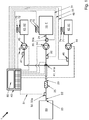
- a fuel additive device 1 can be seen.
- This has a fuel tank 10 to which a delivery line 20 with a first end 21 is connected.
- the fuel tank 10 can, for example, be a fuel depot, an intermediate tank storage facility, be a pipeline or a tank truck each at an airport.
- fuel F can be conducted from the fuel tank 10 to an outlet opening 23 at the second end 22 of the delivery line 20.
- the second end 22 opens into a target container 60.
- a tank truck, tank, storage tank, intermediate tank, a pipeline, a vehicle tank of a motor vehicle or aircraft, in particular an airplane or helicopter, can be considered as the target container 60.
- the fuel F is a liquid turbine fuel (jet fuel).
- a metering device 40 is also provided. This has a data connection to a first sensor system 30 arranged in or on the conveying line 20. This has a data connection 31 to a control unit 80 of the metering device 40. With the first sensor system 30 and the control unit 80 of the metering device 40, a property of the fuel F flowing through the delivery line 20 can be measured.
- the metering device 40 also has a metering interface 41, which is connected to the delivery line 20 between the first sensor system 30 and the outlet opening 23, and has at least two, here in particular exactly two, additive containers 42, 43 each with a liquid additive A1, A2. Furthermore, the metering device 40 is designed to calculate a feed quantity of additive A1, A2 from the additive containers 42, 43 as a function of the properties measured with the first sensor system 30 and the calculated feed quantity of additive A1, A2 via the metering interface 41 into the delivery line 20 to direct. For this purpose, the metering device 40, in particular the control unit 80, is given target values for the properties that are to be achieved by adding additive A1, A2.
- a delivery device 24, in particular a delivery pump, is seated in delivery line 20. This is placed here in particular between the first sensor system 30, which forms a first measuring point 30a, and the outlet opening 23, and in particular between the first sensor system 24 and the metering interface 41, which defines a feed point 41a.
- Both the first sensor system 30 and the metering interface 41 can each optionally extend over the length of a line section of the conveying line 20 and, for example, have several sensors or feed openings located one behind the other in the conveying line 20.
- a mixing device 25 is arranged in the delivery line 20, which has a labyrinth of flow bodies protruding into the flow channel of the delivery line 20. In this area is the Line cross-section of the delivery line 20 widened so that the flow resistance in the mixing device 25 remains low.
- a flow rate sensor 32 can be seen between the fuel tank 10 and the metering device 40, which has a data connection 33 to the metering device 40 or its control unit 80.
- the flow rate of fuel F through the delivery line 20 is determined with the flow rate sensor 32 and the metering device 40. Based on the actually determined flow rate, the feed amount of the additives A1, A2 to be conducted into the delivery line 20 via the metering interface 41 is calculated as a function of the determined flow rate of fuel F.
- the metering device 40 is also designed, inter alia, to regulate the flow of fuel F in the delivery line 20, in particular if additive A1, A2 cannot be conducted into the delivery line 20 or cannot be conducted quickly enough.
- the flow rate of the fuel F in the delivery line 20 and the flow rate of the additive A1, A2 fed in via the feed point 41 are regulated in a closed interval between minimum and maximum flow rates with respect to one another.
- a metered quantity sensor 46, 47 which has a data connection 48, 49 to the metering device 40 or its control unit 80, is also arranged between the additive containers 42, 43 and the metering interface 41. This determines the actual feed-in quantity of additive A1, A2 and regulates it according to the calculated feed-in quantity. In the present case, the volume flow of the additives A1, A2 is also actively brought about with the aid of metering conveying devices 44, 45, in particular by means of metering pumps which are each located between the additive containers 42, 43 and the metering interface 41.
- a second sensor system 50 forms a second measuring point 50a, which is arranged in and / or on the delivery line 20.
- the second sensor system 50 sits between the mixing device 25 and the outlet opening 23.
- the second sensor system 50 has a data connection 51 to the metering device 40 or its control unit 80 of the fuel F flowing through the delivery line 20, which are also measured with the first sensor system 30 and changed by adding the additives A1, A2.
- the additive containers 42, 43 can come from the group of tank trucks, intermediate bulk containers (IBC), barrels or tanks, among others.
- the additive containers 42, 43 are preferably each connected to the metering interface 41 via individual coupling means, so that there can be no mix-ups.
- Such individual coupling means prevent additive containers with different additives from being mixed up.
- the additive containers 42, 43 and the fuel container 10 each have an information carrier 70, 71, 72, the information of which is transmitted to the metering device 40 via a detector 73, 74, 75.
- the information carrier 70 des
- the fuel tank 10 carries information about the fuel type and physical characteristics relating to the target property and optionally a batch number of the fuel F contained in the fuel tank 10.
- the information carriers 71, 72 of the additive tanks 42, 43 each contain information about the additive type and optionally a batch number of the fuel in the additive tank 42, 43 contained additives A1, A2.
- the information carriers 70, 71, 72 each originate from the group consisting of one-dimensional barcodes, two-dimensional barcodes and RFID (radio-frequency identification) transponders.
- the dosing device 40 in particular the control unit 80, can be used to prevent the contents from being removed from the additive containers 42, 43 if the information read does not match the data stored in the dosing device 40.
- a withdrawal valve or a multi-way valve in the metering interface 41 can be closed.
- the metering conveyor devices 44, 45 can be stopped.
- the metering device 40 or its control unit 80 can also have an information processing unit with which the information and measurement data from the group of information from the information carriers 70, 71, 72, the flow rate of fuel F through the delivery line 20, the feed rate of the additive (s) A1, A2, property of the fuel F flowing through the delivery line 20 upstream of the metering interface 41, property of the fuel F flowing through the delivery line 20 downstream of the metering interface 41, place, date, duration of the introduction of an additive, ambient temperature, fuel temperature, operator, contractor, delivery pressure of the delivery device and delivery pressure of the dosing conveyors can be logged.
- an information processing unit with which the information and measurement data from the group of information from the information carriers 70, 71, 72, the flow rate of fuel F through the delivery line 20, the feed rate of the additive (s) A1, A2, property of the fuel F flowing through the delivery line 20 upstream of the metering interface 41, property of the fuel F flowing through the delivery line 20 downstream of the metering interface 41, place, date, duration of the introduction of an additive
- the fuel additive device 1 can be configured in accordance with the alternative embodiments described above and below, or features described as optional are dispensable.
- the method described above and below can be carried out with the fuel additive device 1.
- the fuel additive device 1 can be designed to carry out the method option.
- the method can make use of the configurations of the fuel additive device 1 described above and below.
Landscapes
- Engineering & Computer Science (AREA)
- Physics & Mathematics (AREA)
- General Physics & Mathematics (AREA)
- Automation & Control Theory (AREA)
- Mechanical Engineering (AREA)
- Aviation & Aerospace Engineering (AREA)
- Solid Fuels And Fuel-Associated Substances (AREA)
- Liquid Carbonaceous Fuels (AREA)
Claims (16)
- Dispositif d'additivation de carburant (1) avec un réservoir de carburant (10) et un conduit d'acheminement (20) connectée avec sa première extrémité (21) au réservoir de carburant (10), via laquelle du carburant (F) peut être conduit du réservoir de carburant (10) à un orifice de sortie (23) au niveau de la seconde extrémité (22) du conduit d'acheminement (20),- dans lequel un premier système de détection (30) est agencé dans ou sur le conduit d'acheminement (20), qui présente une liaison de données (31) à un dispositif de dosage (40),- dans lequel le dispositif de dosage (40) est relié au conduit d'acheminement (20) via une interface de dosage (41) entre le premier système de détection (30) et l'orifice de sortie (23), et- dans lequel le dispositif de dosage (40) présente au moins un réservoir d'additif (42, 43),
caractérisé en ce que- une propriété du carburant (F) s'écoulant à travers le conduit d'acheminement (20) peut être mesurée à l'aide du premier système de détection (30) et du dispositif de dosage (40),- et le dispositif de dosage (40) est adapté pour conduire depuis le ou les réservoirs d'additif (42, 43), en fonction des propriétés mesurées, une quantité d'alimentation calculée d'additif (A1, A2) jusque dans le conduit d'acheminement (20) via l'interface de dosage (41). - Dispositif d'additivation de carburant (1) selon la revendication 1, caractérisé en ce que le réservoir de carburant (10) est un dépôt de carburant, un parc de stockage intermédiaire, une canalisation ou un camion-citerne d'un aéroport respectif.
- Dispositif d'additivation de carburant (1) selon la revendication 1 ou 2, caractérisé en ce que le ou les réservoirs d'additif (42, 43) sont connectés respectivement à l'interface de dosage (41) via des moyens de couplage individuels.
- Dispositif d'additivation de carburant (1) selon l'une quelconque des revendications précédentes, caractérisé en ce que le ou les réservoirs d'additif (42, 43) et/ou le réservoir de carburant (10) présente(nt) respectivement un support d'informations (70, 71, 72), dont des informations peuvent être transmises au dispositif de dosage (40) via un détecteur (73, 74, 75) respectif.
- Dispositif d'additivation de carburant (1) selon l'une quelconque des revendications précédentes, caractérisé en ce qu'un second système de détection (50) est agencé dans ou sur le conduit d'acheminement (20) entre le dispositif de dosage (40) et l'orifice de sortie (23), qui présente une liaison de données (51) au dispositif de dosage (40), dans lequel à l'aide du second système de détection (50) et du dispositif de dosage (40), une propriété du carburant (F) s'écoulant à travers le conduit d'acheminement (20) peut être mesurée, qui peut également être mesurée à l'aide du premier système de détection (30).
- Dispositif d'additivation de carburant (1) selon l'une quelconque des revendications précédentes, caractérisé en ce qu'un dispositif de mélange (25) est agencé dans le conduit d'acheminement (20) entre le dispositif de dosage (40) et l'orifice de sortie (23).
- Procédé pour additiver un carburant (F), comprenant les étapes suivantes consistant à- conduire un carburant (F) depuis un réservoir de carburant (10), via un conduit d'acheminement (20) relié avec une première extrémité (21) à un orifice de sortie (23) au niveau d'une seconde extrémité (22) du conduit d'acheminement (20) ;
et caractérisé par les étapes suivantes consistant à :- mesurer au moins une propriété du carburant (F) s'écoulant à travers le conduit d'acheminement (20) au niveau d'un premier emplacement de mesure (30a) ;- calculer une quantité d'alimentation d'additif (A1, A2) calculée en fonction des propriétés mesurées ;- introduire la quantité d'alimentation calculée d'additif (A1, A2) dans le conduit d'acheminement (20) via un emplacement d'introduction (41a) entre le premier emplacement de mesure (30a) et l'orifice de sortie (23). - Procédé selon la revendication 7, caractérisé par les étapes suivantes consistant à :- lire des informations depuis un support d'informations (70, 71, 72) qui est porté par un premier réservoir d'additif (42, 43) contenant un additif (A1, A2) et/ou un réservoir de carburant (10) contenant le carburant (F) ;- calculer, en fonction des propriétés mesurées, la quantité d'alimentation à alimenter de l'additif (A1, A2), en fonction des informations lues.
- Procédé selon l'une des revendications 7 ou 8, caractérisé en ce qu'il présente au moins l'une des étapes du groupe suivant :- une des propriétés mesurées est une conductivité électrique du carburant (F), et comme additif (A1, A2), un additif (A1, A2) est introduit pour ajuster la propriété antistatique du carburant (F) ;- une des propriétés mesurées est la teneur d'eau libre dans le carburant (F), et comme additif (A1, A2), un additif (A1, A2) est introduit pour lier de l'eau dans le carburant (F) ;- une des propriétés mesurées est la stabilité thermique du carburant (F), et comme additif (A1, A2), un additif (A1, A2) est introduit pour améliorer la stabilité thermique du carburant (F) ;- une des propriétés mesurées est le point de congélation d'eau contenue dans le carburant (F), et comme additif (A1, A2), un inhibiteur de gel (A1, A2) est introduit pour améliorer le point de congélation de l'eau contenue dans le carburant (F) ;- une des propriétés mesurées est l'onctuosité du carburant (F), et comme additif (A1, A2), un additif (A1, A2) est introduit pour améliorer l'onctuosité du carburant (F) ; et- une des propriétés mesurées est la teneur en métal du carburant (F), et comme additif (A1, A2), un additif (A1, A2) est introduit pour désactiver des métaux contenus dans le carburant (F).
- Procédé selon l'une des revendications 7 à 9, caractérisé par les étapes suivantes consistant à :- mesurer au moins une des propriétés mesurées au niveau du premier emplacement de mesure (30a) du carburant (F) s'écoulant à travers le conduit d'acheminement (20), au niveau d'un second emplacement de mesure (50a) entre l'emplacement d'alimentation (41a) et l'orifice de sortie (23), et- régler la quantité d'alimentation calculée d'additif (A1, A2) par un calcul de correction de la quantité d'alimentation calculée, dans lequel le calcul de correction est en fonction de la propriété mesurée au niveau du second emplacement de mesure (50a), à une valeur cible pour la propriété mesurée au niveau du second emplacement de mesure (50a), dans lequel la valeur cible se situe entre une valeur limite supérieure et une valeur limite inférieure.
- Procédé selon l'une des revendications 7 à 10, caractérisé par l'étape suivante consistant à :- mélanger le carburant (F) et l'additif (A1, A2) introduit via l'emplacement d'alimentation (41a) avant l'orifice de sortie (23).
- Procédé selon l'une des revendications 7 à 11, caractérisé par les étapes suivantes consistant à :- mesurer le débit d'écoulement du carburant (F) conduit à travers le conduit d'acheminement (20) entre la première extrémité (21) et l'emplacement d'alimentation (41a) ;- calculer, en fonction du débit d'écoulement mesuré, la quantité d'alimentation d'additif (A1, A2) à alimenter en fonction des propriétés mesurées.
- Procédé selon l'une des revendications 7 à 12, caractérisé par les étapes suivantes consistant à :- mesurer la quantité d'alimentation de l'additif (A1, A2) introduite effectivement dans le conduit d'acheminement (20) via l'emplacement d'introduction (41a) ;- régler la quantité d'alimentation de l'additif (A1, A2) sur la base de la quantité d'alimentation effectivement mesurée.
- Procédé selon l'une des revendications 7 à 13, caractérisé par l'étape suivante consistant à :- enregistrer des données du groupe des informations et données mesurées suivantes :- informations du support d'informations (70, 71, 72) ;- débit d'écoulement de carburant (F) à travers le conduit d'acheminement (20) ;- quantité d'alimentation du ou des additif(s) (A1, A2) ;- propriété du carburant (F) s'écoulant à travers le conduit d'acheminement (20) avant l'emplacement d'alimentation (41a) ;- propriété du carburant (F) s'écoulant à travers le conduit d'acheminement (20) derrière l'emplacement d'alimentation (41a) ;- lieu ;- date ;- durée de l'introduction d'un additif ;- température ambiante ;- température de carburant ;- opérateur ;- fournisseur ;- pression d'alimentation du dispositif d'acheminement ; et- pression d'alimentation des dispositifs d'acheminement de dosage.
- Procédé selon la revendication 14, caractérisé par les étapes suivantes sur la base des informations et données mesurées enregistrées consistant à :- introduire automatiquement une commande supplémentaire de carburant (F) ; ou- introduire automatiquement une commande supplémentaire d'additif (A1, A2) ; ou- élaborer un planificateur logique automatique pour l'approvisionnement en additif (A1, A2) ; ou- élaborer automatiquement une position de facturation pour l'obtention d'une facture client.
- Utilisation d'un dispositif d'additivation de carburant (1) selon l'une des revendications 1 à 6 pour mettre en œuvre le procédé selon l'une des revendications 7 à 15 pendant le ravitaillement d'un aéronef.
Applications Claiming Priority (2)
| Application Number | Priority Date | Filing Date | Title |
|---|---|---|---|
| DE102016107522.1A DE102016107522A1 (de) | 2016-04-22 | 2016-04-22 | Kraftstoffadditivierungsvorrichtung, Verfahren zur Additivierung eines Kraftstoffs und Verwendung von diesen |
| PCT/EP2017/053565 WO2017182160A1 (fr) | 2016-04-22 | 2017-02-16 | Dispositif d'additivation de carburant, procédé d'additivation d'un carburant et leur utilisation |
Publications (2)
| Publication Number | Publication Date |
|---|---|
| EP3446191A1 EP3446191A1 (fr) | 2019-02-27 |
| EP3446191B1 true EP3446191B1 (fr) | 2021-04-07 |
Family
ID=58162527
Family Applications (1)
| Application Number | Title | Priority Date | Filing Date |
|---|---|---|---|
| EP17707204.8A Active EP3446191B1 (fr) | 2016-04-22 | 2017-02-16 | Dispositif d'additivation de carburant, procédé d'additivation d'un carburant et leur utilisation |
Country Status (3)
| Country | Link |
|---|---|
| EP (1) | EP3446191B1 (fr) |
| DE (1) | DE102016107522A1 (fr) |
| WO (1) | WO2017182160A1 (fr) |
Cited By (1)
| Publication number | Priority date | Publication date | Assignee | Title |
|---|---|---|---|---|
| RU215424U1 (ru) * | 2022-09-26 | 2022-12-13 | Закрытое акционерное общество НПО "Авиатехнология" | Устройство дозированного ввода противоводокристаллизационной жидкости в авиационное топливо |
Families Citing this family (7)
| Publication number | Priority date | Publication date | Assignee | Title |
|---|---|---|---|---|
| DE102017011356A1 (de) * | 2017-12-06 | 2019-06-06 | Bartec Benke Gmbh | Vorrichtung zur Erfassung wenigstens einer Messgröße von Treibstoff, insbesondere von Flugtreibstoff |
| CN108377707B (zh) * | 2018-01-30 | 2020-12-01 | 阮炳旭 | 一种农业机械施肥装置 |
| FR3082957B1 (fr) * | 2018-06-21 | 2020-07-24 | Herve Lafourcade | Dispositif et procede d'additivation de carburant |
| CN111196594A (zh) * | 2019-12-30 | 2020-05-26 | 西安航天泵业有限公司 | 一种添加剂加注装置及加注方法 |
| CN111912876A (zh) * | 2020-06-15 | 2020-11-10 | 西安科技大学 | 基于爆炸压力与自由基耦合关系的抑爆介质选择方法 |
| CN113639203A (zh) * | 2021-08-13 | 2021-11-12 | 北京双吉制药有限公司 | 一种制药用注射水的配送系统 |
| CN117167669A (zh) * | 2023-10-13 | 2023-12-05 | 北京楚翔飞科技开发有限责任公司 | 抗静电剂添加系统、方法及航煤生产系统 |
Family Cites Families (21)
| Publication number | Priority date | Publication date | Assignee | Title |
|---|---|---|---|---|
| DE1271877B (de) | 1963-04-23 | 1968-07-04 | Lubrizol Corp | Schmieroel |
| US4234435A (en) | 1979-02-23 | 1980-11-18 | The Lubrizol Corporation | Novel carboxylic acid acylating agents, derivatives thereof, concentrate and lubricant compositions containing the same, and processes for their preparation |
| US4849572A (en) | 1987-12-22 | 1989-07-18 | Exxon Chemical Patents Inc. | Process for preparing polybutenes having enhanced reactivity using boron trifluoride catalysts (PT-647) |
| US4904401A (en) | 1988-06-13 | 1990-02-27 | The Lubrizol Corporation | Lubricating oil compositions |
| US5621154A (en) | 1994-04-19 | 1997-04-15 | Betzdearborn Inc. | Methods for reducing fouling deposit formation in jet engines |
| US5569644A (en) | 1995-05-18 | 1996-10-29 | The Lubrizol Corporation | Additive combinations for lubricants and functional fluids |
| GB9618546D0 (en) | 1996-09-05 | 1996-10-16 | Bp Chemicals Additives | Dispersants/detergents for hydrocarbons fuels |
| WO2000053699A1 (fr) | 1999-03-06 | 2000-09-14 | The Burwood Corporation Limited | Compositions destinees a la preparation de microemulsions eau-dans-huile |
| ATE387953T1 (de) | 1997-05-02 | 2008-03-15 | Palox Offshore S A L | Mikroemulsionen |
| US6165235A (en) | 1997-08-26 | 2000-12-26 | The Lubrizol Corporation | Low chlorine content compositions for use in lubricants and fuels |
| DE19948114A1 (de) | 1999-10-06 | 2001-04-12 | Basf Ag | Verfahren zur Herstellung Polyisobutenphenol-haltiger Mannichaddukte |
| DE19948111A1 (de) | 1999-10-06 | 2001-04-12 | Basf Ag | Verfahren zur Herstellung Polyisobutenphenol-haltiger Mannichaddukte |
| GB2434372A (en) | 2006-01-20 | 2007-07-25 | Palox Offshore S A L | Water-in-oil microemulsions |
| SG170045A1 (en) | 2006-02-27 | 2011-04-29 | Basf Se | Use of polynuclear phenolic compounds as stabilisers |
| DE502008001942D1 (de) | 2007-03-02 | 2011-01-13 | Basf Se | Zur antistatikausrüstung und verbesserung der elektrischen leitfähigkeit von unbelebtem organischen material geeignete additivformulierung |
| WO2009092001A2 (fr) * | 2008-01-17 | 2009-07-23 | Clean Emission Fluids Inc. | Appareil de station essence et procédé l'utilisant |
| DE102008056559B4 (de) | 2008-11-10 | 2011-07-07 | Faudi Aviation GmbH, 35260 | Sensoranordnung |
| WO2011024191A2 (fr) * | 2009-07-24 | 2011-03-03 | Fat Biofules Technology Private Limited | Support de stockage, de mélange et de distribution de carburant portatif à système de commande de dosage électronique multicanaux intégré |
| KR102060231B1 (ko) | 2009-10-14 | 2019-12-27 | 팰록스 리미티드 | 액체 연료의 보호 |
| GB201001923D0 (en) | 2010-02-05 | 2010-03-24 | Palox Offshore S A L | Protection of liquid fuels |
| GB2510549A (en) * | 2012-08-29 | 2014-08-13 | Nch Europ Inc Lab | Automatic Fluid Dosage System for Storage Tanks |
-
2016
- 2016-04-22 DE DE102016107522.1A patent/DE102016107522A1/de not_active Withdrawn
-
2017
- 2017-02-16 WO PCT/EP2017/053565 patent/WO2017182160A1/fr not_active Ceased
- 2017-02-16 EP EP17707204.8A patent/EP3446191B1/fr active Active
Non-Patent Citations (1)
| Title |
|---|
| None * |
Cited By (5)
| Publication number | Priority date | Publication date | Assignee | Title |
|---|---|---|---|---|
| RU215424U1 (ru) * | 2022-09-26 | 2022-12-13 | Закрытое акционерное общество НПО "Авиатехнология" | Устройство дозированного ввода противоводокристаллизационной жидкости в авиационное топливо |
| RU217810U1 (ru) * | 2023-02-10 | 2023-04-19 | Закрытое акционерное общество НПО "Авиатехнология" | Устройство выдачи топлива в цистерны и транспортные меры вместимости |
| RU217827U1 (ru) * | 2023-02-10 | 2023-04-20 | Закрытое акционерное общество НПО "Авиатехнология" | Устройство выдачи топлива в воздушное судно |
| RU221123U1 (ru) * | 2023-07-14 | 2023-10-19 | Закрытое акционерное общество НПО "Авиатехнология" | Устройство автоматизированного дозированного ввода противоводокристаллизационной жидкости в авиационное топливо в массе |
| RU222374U1 (ru) * | 2023-07-14 | 2023-12-21 | Закрытое акционерное общество НПО "Авиатехнология" | Устройство автоматизированного дозированного ввода азота в авиационное топливо |
Also Published As
| Publication number | Publication date |
|---|---|
| WO2017182160A1 (fr) | 2017-10-26 |
| EP3446191A1 (fr) | 2019-02-27 |
| DE102016107522A1 (de) | 2017-10-26 |
Similar Documents
| Publication | Publication Date | Title |
|---|---|---|
| EP3446191B1 (fr) | Dispositif d'additivation de carburant, procédé d'additivation d'un carburant et leur utilisation | |
| DE112020001160B4 (de) | Kontrolliertes mischen von transmix-fraktionen in definierte kohlenwasserstoffströme | |
| DE69518546T2 (de) | Additivmischsystem und verfahren | |
| DE602004010648T2 (de) | Verfahren zur aufwertung von kerosin- und gasölschnitten aus rohöl | |
| DE19732510A1 (de) | System und Verfahren zur Wiedergewinnung eines Flüssigtreibstoffdampf-Luft-Gemisches aus einem Fahrzeugtank | |
| DE102008033454A1 (de) | Öl-/Luft-Schmiersystem | |
| EP3795814A1 (fr) | Procédé de détection d'une composition de carburant permettant de limiter la possibilité d'utilisation d'un véhicule en cas d'un ravitaillement incorrect | |
| DE102013003999A1 (de) | Verfahren zum Betanken eines Speicherbehälters mit einem gasförmigen, unter Druck stehenden Medium, insbesondere Wasserstoff | |
| DE102008061192A1 (de) | Gasversorgungsanlage für einen Antrieb | |
| EP3441760A1 (fr) | Dispositif de ravitaillement destiné à ravitailler un réservoir de carburant d'un moteur à combustion interne, système de ravitaillement et procédé de ravitaillement | |
| EP3717139B1 (fr) | Dispositif et procédé pour l'odorisation d'un flux gazeux dans une conduite de gaz | |
| DE102017214098A1 (de) | Betankungsvorrichtung zum Betanken eines Kraftstofftanks einer Brennkraftmaschine, Betankungssystem und Betankungsverfahren | |
| EP0210294A1 (fr) | Procédé et dispositif de préparation de suspensions à caractéristiques constantes provenant d'éléments à propriétés variables | |
| AT401435B (de) | Verfahren zur druckprüfung eines zur lagerung von flüssiggas vorgesehenen flüssiggasbehälters | |
| US20170082594A1 (en) | Methods for reducing the precipitation propensity of asphaltenes in blended crude oils | |
| DE202005010318U1 (de) | System zur Abgabe von zwei unterschiedlichen Brennstoffarten an einer Tankstelle | |
| DE60022674T2 (de) | Methode zur verbesserung eines thermischen crackverfahrens und der damit erzielten produktausbeuten | |
| EP0667484B1 (fr) | Procédé pour la mise en pression ciblée d'un réservoir à gaz liquide | |
| DE8806777U1 (de) | Vorrichtung zum Messen der in einem Tank befindlichen Flüssigkeitsmenge, insbesondere der Flüssigtreibstoffmenge in Satellitentanks unter Schwerelosigkeit | |
| DE3879430T2 (de) | Verfahren zur verbesserung der ausbeute in oelinstallationen, insbesondere von mitteldestillaten. | |
| US9795935B2 (en) | Method and system for blending natural gas liquids into hydrocarbons | |
| EP2199754A1 (fr) | Procédé et dispositif de transmission d'un liquide contenant au moins ponctuellement une insufflation de gaz et de détermination de la quantité de liquide transmise | |
| DE202005009735U1 (de) | System zur Abgabe und zum Mischen von zwei unterschiedlichen Brennstoffarten an einer Tankstelle | |
| DE3034622A1 (de) | Verfahren und vorrichtung zum herstellen von schaum | |
| EP4123215B1 (fr) | Installation d'essai d'odoration permettant d'odorifier à titre d'essai un mélange gazeux coulant dans une conduite de gaz |
Legal Events
| Date | Code | Title | Description |
|---|---|---|---|
| STAA | Information on the status of an ep patent application or granted ep patent |
Free format text: STATUS: UNKNOWN |
|
| STAA | Information on the status of an ep patent application or granted ep patent |
Free format text: STATUS: THE INTERNATIONAL PUBLICATION HAS BEEN MADE |
|
| PUAI | Public reference made under article 153(3) epc to a published international application that has entered the european phase |
Free format text: ORIGINAL CODE: 0009012 |
|
| STAA | Information on the status of an ep patent application or granted ep patent |
Free format text: STATUS: REQUEST FOR EXAMINATION WAS MADE |
|
| 17P | Request for examination filed |
Effective date: 20181115 |
|
| AK | Designated contracting states |
Kind code of ref document: A1 Designated state(s): AL AT BE BG CH CY CZ DE DK EE ES FI FR GB GR HR HU IE IS IT LI LT LU LV MC MK MT NL NO PL PT RO RS SE SI SK SM TR |
|
| AX | Request for extension of the european patent |
Extension state: BA ME |
|
| DAV | Request for validation of the european patent (deleted) | ||
| DAX | Request for extension of the european patent (deleted) | ||
| GRAP | Despatch of communication of intention to grant a patent |
Free format text: ORIGINAL CODE: EPIDOSNIGR1 |
|
| STAA | Information on the status of an ep patent application or granted ep patent |
Free format text: STATUS: GRANT OF PATENT IS INTENDED |
|
| RIC1 | Information provided on ipc code assigned before grant |
Ipc: G05D 21/02 20060101ALI20200313BHEP Ipc: F17D 3/12 20060101ALI20200313BHEP Ipc: B64F 1/28 20060101ALI20200313BHEP Ipc: B64D 37/30 20060101ALI20200313BHEP Ipc: G05D 11/13 20060101ALI20200313BHEP Ipc: C10L 10/00 20060101ALI20200313BHEP Ipc: B67D 7/04 20100101ALI20200313BHEP Ipc: G05D 11/00 20060101AFI20200313BHEP |
|
| INTG | Intention to grant announced |
Effective date: 20200409 |
|
| GRAJ | Information related to disapproval of communication of intention to grant by the applicant or resumption of examination proceedings by the epo deleted |
Free format text: ORIGINAL CODE: EPIDOSDIGR1 |
|
| STAA | Information on the status of an ep patent application or granted ep patent |
Free format text: STATUS: REQUEST FOR EXAMINATION WAS MADE |
|
| INTC | Intention to grant announced (deleted) | ||
| GRAP | Despatch of communication of intention to grant a patent |
Free format text: ORIGINAL CODE: EPIDOSNIGR1 |
|
| STAA | Information on the status of an ep patent application or granted ep patent |
Free format text: STATUS: GRANT OF PATENT IS INTENDED |
|
| INTG | Intention to grant announced |
Effective date: 20200918 |
|
| GRAS | Grant fee paid |
Free format text: ORIGINAL CODE: EPIDOSNIGR3 |
|
| GRAA | (expected) grant |
Free format text: ORIGINAL CODE: 0009210 |
|
| STAA | Information on the status of an ep patent application or granted ep patent |
Free format text: STATUS: THE PATENT HAS BEEN GRANTED |
|
| RAP1 | Party data changed (applicant data changed or rights of an application transferred) |
Owner name: FAUDI AVIATION GMBH |
|
| AK | Designated contracting states |
Kind code of ref document: B1 Designated state(s): AL AT BE BG CH CY CZ DE DK EE ES FI FR GB GR HR HU IE IS IT LI LT LU LV MC MK MT NL NO PL PT RO RS SE SI SK SM TR |
|
| REG | Reference to a national code |
Ref country code: GB Ref legal event code: FG4D Free format text: NOT ENGLISH |
|
| REG | Reference to a national code |
Ref country code: AT Ref legal event code: REF Ref document number: 1380528 Country of ref document: AT Kind code of ref document: T Effective date: 20210415 Ref country code: CH Ref legal event code: EP |
|
| REG | Reference to a national code |
Ref country code: DE Ref legal event code: R096 Ref document number: 502017009993 Country of ref document: DE |
|
| REG | Reference to a national code |
Ref country code: IE Ref legal event code: FG4D Free format text: LANGUAGE OF EP DOCUMENT: GERMAN |
|
| REG | Reference to a national code |
Ref country code: LT Ref legal event code: MG9D |
|
| REG | Reference to a national code |
Ref country code: NL Ref legal event code: MP Effective date: 20210407 |
|
| PG25 | Lapsed in a contracting state [announced via postgrant information from national office to epo] |
Ref country code: NL Free format text: LAPSE BECAUSE OF FAILURE TO SUBMIT A TRANSLATION OF THE DESCRIPTION OR TO PAY THE FEE WITHIN THE PRESCRIBED TIME-LIMIT Effective date: 20210407 Ref country code: HR Free format text: LAPSE BECAUSE OF FAILURE TO SUBMIT A TRANSLATION OF THE DESCRIPTION OR TO PAY THE FEE WITHIN THE PRESCRIBED TIME-LIMIT Effective date: 20210407 Ref country code: BG Free format text: LAPSE BECAUSE OF FAILURE TO SUBMIT A TRANSLATION OF THE DESCRIPTION OR TO PAY THE FEE WITHIN THE PRESCRIBED TIME-LIMIT Effective date: 20210707 Ref country code: FI Free format text: LAPSE BECAUSE OF FAILURE TO SUBMIT A TRANSLATION OF THE DESCRIPTION OR TO PAY THE FEE WITHIN THE PRESCRIBED TIME-LIMIT Effective date: 20210407 Ref country code: LT Free format text: LAPSE BECAUSE OF FAILURE TO SUBMIT A TRANSLATION OF THE DESCRIPTION OR TO PAY THE FEE WITHIN THE PRESCRIBED TIME-LIMIT Effective date: 20210407 |
|
| PG25 | Lapsed in a contracting state [announced via postgrant information from national office to epo] |
Ref country code: IS Free format text: LAPSE BECAUSE OF FAILURE TO SUBMIT A TRANSLATION OF THE DESCRIPTION OR TO PAY THE FEE WITHIN THE PRESCRIBED TIME-LIMIT Effective date: 20210807 Ref country code: GR Free format text: LAPSE BECAUSE OF FAILURE TO SUBMIT A TRANSLATION OF THE DESCRIPTION OR TO PAY THE FEE WITHIN THE PRESCRIBED TIME-LIMIT Effective date: 20210708 Ref country code: LV Free format text: LAPSE BECAUSE OF FAILURE TO SUBMIT A TRANSLATION OF THE DESCRIPTION OR TO PAY THE FEE WITHIN THE PRESCRIBED TIME-LIMIT Effective date: 20210407 Ref country code: PL Free format text: LAPSE BECAUSE OF FAILURE TO SUBMIT A TRANSLATION OF THE DESCRIPTION OR TO PAY THE FEE WITHIN THE PRESCRIBED TIME-LIMIT Effective date: 20210407 Ref country code: NO Free format text: LAPSE BECAUSE OF FAILURE TO SUBMIT A TRANSLATION OF THE DESCRIPTION OR TO PAY THE FEE WITHIN THE PRESCRIBED TIME-LIMIT Effective date: 20210707 Ref country code: PT Free format text: LAPSE BECAUSE OF FAILURE TO SUBMIT A TRANSLATION OF THE DESCRIPTION OR TO PAY THE FEE WITHIN THE PRESCRIBED TIME-LIMIT Effective date: 20210809 Ref country code: RS Free format text: LAPSE BECAUSE OF FAILURE TO SUBMIT A TRANSLATION OF THE DESCRIPTION OR TO PAY THE FEE WITHIN THE PRESCRIBED TIME-LIMIT Effective date: 20210407 Ref country code: SE Free format text: LAPSE BECAUSE OF FAILURE TO SUBMIT A TRANSLATION OF THE DESCRIPTION OR TO PAY THE FEE WITHIN THE PRESCRIBED TIME-LIMIT Effective date: 20210407 |
|
| REG | Reference to a national code |
Ref country code: DE Ref legal event code: R097 Ref document number: 502017009993 Country of ref document: DE |
|
| PG25 | Lapsed in a contracting state [announced via postgrant information from national office to epo] |
Ref country code: CZ Free format text: LAPSE BECAUSE OF FAILURE TO SUBMIT A TRANSLATION OF THE DESCRIPTION OR TO PAY THE FEE WITHIN THE PRESCRIBED TIME-LIMIT Effective date: 20210407 Ref country code: DK Free format text: LAPSE BECAUSE OF FAILURE TO SUBMIT A TRANSLATION OF THE DESCRIPTION OR TO PAY THE FEE WITHIN THE PRESCRIBED TIME-LIMIT Effective date: 20210407 Ref country code: EE Free format text: LAPSE BECAUSE OF FAILURE TO SUBMIT A TRANSLATION OF THE DESCRIPTION OR TO PAY THE FEE WITHIN THE PRESCRIBED TIME-LIMIT Effective date: 20210407 Ref country code: RO Free format text: LAPSE BECAUSE OF FAILURE TO SUBMIT A TRANSLATION OF THE DESCRIPTION OR TO PAY THE FEE WITHIN THE PRESCRIBED TIME-LIMIT Effective date: 20210407 Ref country code: ES Free format text: LAPSE BECAUSE OF FAILURE TO SUBMIT A TRANSLATION OF THE DESCRIPTION OR TO PAY THE FEE WITHIN THE PRESCRIBED TIME-LIMIT Effective date: 20210407 Ref country code: SK Free format text: LAPSE BECAUSE OF FAILURE TO SUBMIT A TRANSLATION OF THE DESCRIPTION OR TO PAY THE FEE WITHIN THE PRESCRIBED TIME-LIMIT Effective date: 20210407 Ref country code: SM Free format text: LAPSE BECAUSE OF FAILURE TO SUBMIT A TRANSLATION OF THE DESCRIPTION OR TO PAY THE FEE WITHIN THE PRESCRIBED TIME-LIMIT Effective date: 20210407 |
|
| PLBE | No opposition filed within time limit |
Free format text: ORIGINAL CODE: 0009261 |
|
| STAA | Information on the status of an ep patent application or granted ep patent |
Free format text: STATUS: NO OPPOSITION FILED WITHIN TIME LIMIT |
|
| 26N | No opposition filed |
Effective date: 20220110 |
|
| PG25 | Lapsed in a contracting state [announced via postgrant information from national office to epo] |
Ref country code: IS Free format text: LAPSE BECAUSE OF FAILURE TO SUBMIT A TRANSLATION OF THE DESCRIPTION OR TO PAY THE FEE WITHIN THE PRESCRIBED TIME-LIMIT Effective date: 20210807 Ref country code: AL Free format text: LAPSE BECAUSE OF FAILURE TO SUBMIT A TRANSLATION OF THE DESCRIPTION OR TO PAY THE FEE WITHIN THE PRESCRIBED TIME-LIMIT Effective date: 20210407 |
|
| PG25 | Lapsed in a contracting state [announced via postgrant information from national office to epo] |
Ref country code: IT Free format text: LAPSE BECAUSE OF FAILURE TO SUBMIT A TRANSLATION OF THE DESCRIPTION OR TO PAY THE FEE WITHIN THE PRESCRIBED TIME-LIMIT Effective date: 20210407 |
|
| PG25 | Lapsed in a contracting state [announced via postgrant information from national office to epo] |
Ref country code: MC Free format text: LAPSE BECAUSE OF FAILURE TO SUBMIT A TRANSLATION OF THE DESCRIPTION OR TO PAY THE FEE WITHIN THE PRESCRIBED TIME-LIMIT Effective date: 20210407 |
|
| REG | Reference to a national code |
Ref country code: CH Ref legal event code: PL |
|
| REG | Reference to a national code |
Ref country code: BE Ref legal event code: MM Effective date: 20220228 |
|
| PG25 | Lapsed in a contracting state [announced via postgrant information from national office to epo] |
Ref country code: LU Free format text: LAPSE BECAUSE OF NON-PAYMENT OF DUE FEES Effective date: 20220216 |
|
| PG25 | Lapsed in a contracting state [announced via postgrant information from national office to epo] |
Ref country code: LI Free format text: LAPSE BECAUSE OF NON-PAYMENT OF DUE FEES Effective date: 20220228 Ref country code: IE Free format text: LAPSE BECAUSE OF NON-PAYMENT OF DUE FEES Effective date: 20220216 Ref country code: CH Free format text: LAPSE BECAUSE OF NON-PAYMENT OF DUE FEES Effective date: 20220228 |
|
| PG25 | Lapsed in a contracting state [announced via postgrant information from national office to epo] |
Ref country code: BE Free format text: LAPSE BECAUSE OF NON-PAYMENT OF DUE FEES Effective date: 20220228 |
|
| REG | Reference to a national code |
Ref country code: AT Ref legal event code: MM01 Ref document number: 1380528 Country of ref document: AT Kind code of ref document: T Effective date: 20220216 |
|
| PG25 | Lapsed in a contracting state [announced via postgrant information from national office to epo] |
Ref country code: AT Free format text: LAPSE BECAUSE OF NON-PAYMENT OF DUE FEES Effective date: 20220216 |
|
| PG25 | Lapsed in a contracting state [announced via postgrant information from national office to epo] |
Ref country code: HU Free format text: LAPSE BECAUSE OF FAILURE TO SUBMIT A TRANSLATION OF THE DESCRIPTION OR TO PAY THE FEE WITHIN THE PRESCRIBED TIME-LIMIT; INVALID AB INITIO Effective date: 20170216 |
|
| PG25 | Lapsed in a contracting state [announced via postgrant information from national office to epo] |
Ref country code: MK Free format text: LAPSE BECAUSE OF FAILURE TO SUBMIT A TRANSLATION OF THE DESCRIPTION OR TO PAY THE FEE WITHIN THE PRESCRIBED TIME-LIMIT Effective date: 20210407 Ref country code: CY Free format text: LAPSE BECAUSE OF FAILURE TO SUBMIT A TRANSLATION OF THE DESCRIPTION OR TO PAY THE FEE WITHIN THE PRESCRIBED TIME-LIMIT Effective date: 20210407 |
|
| PG25 | Lapsed in a contracting state [announced via postgrant information from national office to epo] |
Ref country code: MT Free format text: LAPSE BECAUSE OF FAILURE TO SUBMIT A TRANSLATION OF THE DESCRIPTION OR TO PAY THE FEE WITHIN THE PRESCRIBED TIME-LIMIT Effective date: 20210407 |
|
| PGFP | Annual fee paid to national office [announced via postgrant information from national office to epo] |
Ref country code: DE Payment date: 20250228 Year of fee payment: 9 |
|
| PGFP | Annual fee paid to national office [announced via postgrant information from national office to epo] |
Ref country code: FR Payment date: 20250227 Year of fee payment: 9 |
|
| PGFP | Annual fee paid to national office [announced via postgrant information from national office to epo] |
Ref country code: GB Payment date: 20250227 Year of fee payment: 9 |
|
| PG25 | Lapsed in a contracting state [announced via postgrant information from national office to epo] |
Ref country code: TR Free format text: LAPSE BECAUSE OF FAILURE TO SUBMIT A TRANSLATION OF THE DESCRIPTION OR TO PAY THE FEE WITHIN THE PRESCRIBED TIME-LIMIT Effective date: 20210407 |