EP3441549A1 - Türverriegelung - Google Patents
Türverriegelung Download PDFInfo
- Publication number
- EP3441549A1 EP3441549A1 EP17185539.8A EP17185539A EP3441549A1 EP 3441549 A1 EP3441549 A1 EP 3441549A1 EP 17185539 A EP17185539 A EP 17185539A EP 3441549 A1 EP3441549 A1 EP 3441549A1
- Authority
- EP
- European Patent Office
- Prior art keywords
- movable
- bolt
- door
- handle
- slider
- Prior art date
- Legal status (The legal status is an assumption and is not a legal conclusion. Google has not performed a legal analysis and makes no representation as to the accuracy of the status listed.)
- Granted
Links
Images




Classifications
-
- E—FIXED CONSTRUCTIONS
- E05—LOCKS; KEYS; WINDOW OR DOOR FITTINGS; SAFES
- E05B—LOCKS; ACCESSORIES THEREFOR; HANDCUFFS
- E05B65/00—Locks or fastenings for special use
- E05B65/06—Locks or fastenings for special use for swing doors or windows, i.e. opening inwards and outwards
-
- E—FIXED CONSTRUCTIONS
- E05—LOCKS; KEYS; WINDOW OR DOOR FITTINGS; SAFES
- E05B—LOCKS; ACCESSORIES THEREFOR; HANDCUFFS
- E05B47/00—Operating or controlling locks or other fastening devices by electric or magnetic means
- E05B47/0038—Operating or controlling locks or other fastening devices by electric or magnetic means using permanent magnets
-
- E—FIXED CONSTRUCTIONS
- E05—LOCKS; KEYS; WINDOW OR DOOR FITTINGS; SAFES
- E05B—LOCKS; ACCESSORIES THEREFOR; HANDCUFFS
- E05B53/00—Operation or control of locks by mechanical transmissions, e.g. from a distance
- E05B53/003—Operation or control of locks by mechanical transmissions, e.g. from a distance flexible
- E05B53/005—Bowden
-
- E—FIXED CONSTRUCTIONS
- E05—LOCKS; KEYS; WINDOW OR DOOR FITTINGS; SAFES
- E05B—LOCKS; ACCESSORIES THEREFOR; HANDCUFFS
- E05B65/00—Locks or fastenings for special use
- E05B65/0007—Locks or fastenings for special use for gates
-
- E—FIXED CONSTRUCTIONS
- E05—LOCKS; KEYS; WINDOW OR DOOR FITTINGS; SAFES
- E05B—LOCKS; ACCESSORIES THEREFOR; HANDCUFFS
- E05B65/00—Locks or fastenings for special use
- E05B65/0075—Locks or fastenings for special use for safes, strongrooms, vaults, fire-resisting cabinets or the like
- E05B65/0078—Safety means for persons trapped within the safe, e.g. release from inside, venting means
-
- E—FIXED CONSTRUCTIONS
- E05—LOCKS; KEYS; WINDOW OR DOOR FITTINGS; SAFES
- E05C—BOLTS OR FASTENING DEVICES FOR WINGS, SPECIALLY FOR DOORS OR WINDOWS
- E05C1/00—Fastening devices with bolts moving rectilinearly
- E05C1/02—Fastening devices with bolts moving rectilinearly without latching action
- E05C1/04—Fastening devices with bolts moving rectilinearly without latching action with operating handle or equivalent member rigid with the bolt
-
- E—FIXED CONSTRUCTIONS
- E06—DOORS, WINDOWS, SHUTTERS, OR ROLLER BLINDS IN GENERAL; LADDERS
- E06B—FIXED OR MOVABLE CLOSURES FOR OPENINGS IN BUILDINGS, VEHICLES, FENCES OR LIKE ENCLOSURES IN GENERAL, e.g. DOORS, WINDOWS, BLINDS, GATES
- E06B11/00—Means for allowing passage through fences, barriers or the like, e.g. stiles
- E06B11/02—Gates; Doors
- E06B11/021—Wire gates, e.g. traction gates; Fastenings therefor
Definitions
- the present invention relates to a door lock according to the preamble of claim 1.
- Such a mechanical bolt typically consists of two parts: a movable assembly for attachment to the door itself, including the bolt, and a rigid part with a guide for the bolt, which is mounted on the door frame.
- An escape release for mechanical slide pins is typically realized by a simple rigid bolt or handle attached to the back of the movable slide Bolzens is attached. To open a door out of the danger zone, the escape release handle must simply be moved in a sliding direction.
- a disadvantage is that a slot must be cut into the door, which is additional work to be avoided during installation.
- An object of the invention is to provide an escape release function for a mechanical bolt for the locking of doors, which can be used without the need to cut a slot in the door.
- a door lock with a movable mechanical bolt and a first handle connected to the bolt on the outside of the door, with which the mechanical bolt is movable on a mounting plate, and a receiving part with a guide for the bolt a frame of the door, with a second handle on an inside of the door, with which the mechanical bolt is movable, wherein the mechanical bolt is movable via a wire rope through the second handle, wherein the second handle is a pull-handle.
- the mechanism according to the invention is simple and robust. There are only a few parts needed, so the cost is low.
- a slot is arranged in the mounting plate, wherein in the slot a movable slide is arranged, which is movable in guide rails of the slot, wherein the movable slide is connected via the wire with the second handle, wherein the mechanical bolt is movable by the slider.
- the slot is integrated.
- This slot also contains two guide rails on the left and right longitudinal side of the slot. These guide rails are used to guide the movable slide, which can be moved back and forth in the slot.
- the thin wire rope is connected at one end to the slider. The wire rope is then guided to the pull handle.
- the mounting plate on a hole for guiding the wire rope.
- the wire rope is then passed through the hole in the mounting plate or base plate to the pull handle.
- the mechanical pin on pins which protrude into the slot, wherein the slider presses against the pins in a movement and thereby moves the mechanical pin.
- the bolt In order for the slider to pull the movable bolt to the open position, the bolt includes two pins on its underside that project directly into the slot for the slider. When you pull the slider back to open the bolt and then the door, the slider operates the two pins and then pulls the bolt over the pins to the open position.
- the mounting plate on a first magnet and the movable slider is ferromagnetic or has a second magnet, so that the slider is held by means of magnetic forces on the first magnet.
- the slider with the first magnet is activated held in a basic position.
- the slider itself must be made of a ferromagnetic material or must also contain the second magnet that provides the magnetic attraction. This will ensure that the entire escape release assembly does not move under normal operating conditions.
- a mounting adapter is provided for guiding the wire rope.
- the cable will continue to be guided to a mounting adapter for the pull handle, before it is connected to this.
- the mounting adapter consists for example of a guide for the wire rope and two plate elements that can be screwed against each other.
- the mounting adapter can be easily attached to a fence door.
- the slider, wire rope and pull handle are returned to their original position by moving the bolt only once to its fully closed position. This is to be done while the door is open so as to ensure that the bolt can be moved to the maximum closed position, which also returns the slider to its original position. In addition, it allows the user to ensure that the pull handle can move freely while resetting the escape enable function.
- FIG. 1a shows a closed door 17 to a security area or a hazardous area for persons. For example, access to an area with machines that must not be entered by unauthorized personnel.
- the door 17 is closed.
- the door 17 is open.
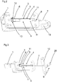
- FIG. 1a and FIG. 1b each show a door lock 14 with a movable mechanical bolt 1 and connected to the bolt 1 first handle 19 on the outside 15 of a door 17 with which the mechanical bolt 1 is movable on a mounting plate and a receiving part 2 with a guide for the bolt on a frame 18 of the door 17, with a second handle 20 mounted on an inner side 16 of the door 17, with which the mechanical bolt 1 is movable, wherein the mechanical bolt 1 is movable by a wire rope 7 through the second handle 20 wherein the second handle 20 is a pull handle 9.
- Figure 1c shows the door lock 14 according to FIG. 1a and FIG. 1b with a movable mechanical bolt 1 and a first handle 19 connected to the bolt 1 on the outside of a door, with which the mechanical bolt 1 is movable on a mounting plate 3, with a second handle 20 which can be mounted on an inside of the door, with which the mechanical bolt 1 is movable, wherein the mechanical bolt 1 via a wire rope 7 by the pull-handle 9 is movable.
- a slot 4 is arranged, wherein in the slot 4, a movable slide 6 is arranged, which is movable in guide rails 5 of the slot 4, wherein the movable slide 6 is connected via the wire rope 7 with the second handle 20, wherein by the slider 6, the mechanical bolt 1 is movable.
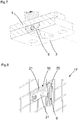
- FIG. 6 is in the mounting plate 3 of the movable bolt, the slot 4 integrated.
- the elongated hole 4 also includes two guide rails 5 on the left and right longitudinal sides of the elongated hole 4. These guide rails 5 are used to guide the movable slider 6, which can be reciprocated in the slot 4 back and forth.
- the thin wire rope 7 is connected at one end to the slider 6. The wire rope 7 is then guided to the pull handle.
- FIG. 5 shows the mounting plate 3 and the movable arranged mechanical bolt. 1
- FIG. 7 is a sectional view according to FIG. 4 by the slider 6, the mounting plate 3 and the mechanical bolt. 1
- the mounting plate 3 has a hole 8 for guiding the wire rope 7.
- the wire rope 7 is then passed through the hole 8 in the mounting plate 3 or the base plate to the pull handle.
- FIG. 2 has the mechanical pin 1 pins 11, which protrude into the slot 4, wherein the slider 6 according to FIG. 3 and FIG. 4 presses against the pins 11 during a movement and thereby moves the mechanical bolt 1.
- the slider 6 can pull the movable pin 1 in the open position, the pin 1 contains the two pins 11 on its underside, which protrude directly into the slot 4 for the slider 6. If you pull back the slider 6 to open the bolt 1 and then the door, the slider 6 actuates the two pins 11 and then pulls the bolt 1 through the pins 11 in the open position.
- the mounting plate 3 has a first magnet 13, and the movable slider 6 is ferromagnetic or has a second magnet, so that the slider 6 is held on the first magnet 13 by means of magnetic forces.
- the slider 6 In order to prevent the slider 6 and the wire rope 7 from being moved back and forth from the outside of a safety or danger zone with each normal opening cycle, and thus also releasing the pull handle 9 and possibly catching it somewhere, the slider 6 is moved according to FIG. 2 held in a basic position 12 with the first magnet 13. To provide a magnetic holding force, the slider 6 itself must be made of a ferromagnetic material or must also contain the second magnet that provides the magnetic attraction. This will ensure that the entire escape release assembly does not move under normal operating conditions.
- FIG. 3 is to guide the wire rope 7, a mounting adapter 10 is provided.
- the wire rope 7 is passed through the mounting adapter 10 to the pull handle 9, before it is connected thereto.
- the mounting adapter 10 is according to FIG. 8 for example, a guide for the wire rope and two plate elements 21 which can be screwed against each other.
- the mounting adapter 10 can be easily fastened to a door 17 or a fence door.
- the slider 6, the wire rope 7 and the pull handle 9 are returned to their original position by moving the bolt 1 only once to its fully closed position. This is to do as long as the door 17 is open, so that it is ensured that the bolt 1 can be moved to the maximum closed position, which also guides the slider 6 back into its starting position. In addition, it allows the user to ensure that the pull handle 9 can move freely while resetting the escape enable function.
Landscapes
- Engineering & Computer Science (AREA)
- Mechanical Engineering (AREA)
- Securing Of Glass Panes Or The Like (AREA)
- Power-Operated Mechanisms For Wings (AREA)
- Lock And Its Accessories (AREA)
Description
- Die vorliegende Erfindung betrifft eine Türverriegelung nach dem Oberbegriff von Anspruch 1.
- Zur Verriegelung von Türen, insbesondere durchgehende Türen, werden in industriellen Umgebungen verschiedene Arten von Verriegelungsvorrichtungen verwendet. Eines dieser Geräte und möglicherweise das einfachste ist ein mechanischer Bolzen, der meistens als Gleitbolzen realisiert wird.
- Ein solcher mechanischer Bolzen besteht typischerweise aus zwei Teilen: einer beweglichen Baugruppe zur Befestigung an der Tür selbst, einschließlich des Bolzens, sowie einem starren Teil mit einer Führung für den Bolzen, der am Türrahmen montiert ist.
- Für einige Anwendungen ist aus Sicherheitsgründen die Möglichkeit erforderlich, die mechanische Tür von der Innenseite eines Sicherheitsbereiches bzw. eines explosionsgefährdeten Bereichs zu öffnen, um zu verhindern, dass Personen in dem explosionsgefährdeten Bereich gefangen werden.
- Um dies zu verwirklichen, wird an der Rückseite des beweglichen Bolzens eine sogenannte "Fluchtentriegelung" installiert, die von dem explosionsgefährdeten Bereich oder dem Sicherheitsbereich aus bedienbar ist. Mit dieser Fluchtfreigabe kann eine Person den Bolzen von Innen öffnen.
- Eine Fluchtentriegelung für mechanische Gleitbolzen wird typischerweise durch einen einfachen starren Bolzen oder Griff realisiert, der an der Rückseite des beweglichen Bolzens angebracht ist. Um eine Tür aus dem Gefahrenbereich zu öffnen, muss der Fluchtentriegelungsgriff einfach in einer Schieberichtung bewegt werden.
- Ein Nachteil dabei ist, dass ein Langloch in die Tür geschnitten werden muss, was bei der Installation zusätzliche Arbeit ist, die vermieden werden soll.
- Eine Aufgabe der Erfindung besteht darin, eine Fluchtentriegelungsfunktion für einen mechanischen Bolzen für die Verriegelung von Türen bereitzustellen, der ohne die Notwendigkeit, ein Langloch in die Tür zu schneiden, verwendet werden kann.
- Die Aufgabe wird gemäß Anspruch 1 gelöst durch eine Türverriegelung mit einem beweglichen mechanischen Bolzen und einem mit dem Bolzen verbundenen ersten Griff an der Außenseite der Tür, mit dem der mechanische Bolzen an einer Montageplatte bewegbar ist, und einem Aufnahmeteil mit einer Führung für den Bolzen an einem Rahmen der Tür, mit einem zweiten Griff an einer Innenseite der Tür, mit dem der mechanische Bolzen bewegbar ist, wobei der mechanische Bolzen über ein Drahtseil durch den zweiten Griff bewegbar ist, wobei der zweite Griff ein Zug-Griff ist.
- Dadurch wird eine Fluchtfreigabe bereitgestellt, ohne dass ein Langloch in der Tür benötigt wird. Gemäß der Erfindung wird nur ein einziges einfaches Loch in der Tür benötigt. Im Falle einer festen Tür ist ein einziges Loch bzw. eine einziges Bohrloch ausreichend.
- Häufig, zum Beispiel im Falle einer Zauntür als Tür, ist dieses Loch bereits ohnehin vorhanden, da die Zauntür bereits Löcher enthält und es muss keine zusätzliche Arbeit gemacht werden. So ist die Installation viel einfacher.
- Weder der Maschinenhersteller noch der Endverbraucher müssen ein Langloch in die Tür bzw. eine Maschinentür schneiden, um eine Fluchtfreigabefunktionalität zu bieten.
- Der Mechanismus gemäß der Erfindung ist einfach und robust. Es sind nur wenige Teile nötig, so dass die Kosten niedrig sind.
- In einer bevorzugten Ausführungsform der Erfindung ist in der Montageplatte ein Langloch angeordnet ist, wobei in dem Langloch ein beweglicher Schieber angeordnet ist, der in Führungsschienen des Langlochs bewegbar ist, wobei der bewegliche Schieber über das Drahtseil mit dem zweiten Griff verbunden ist, wobei durch den Schieber der mechanische Bolzen bewegbar ist.
- In der Montageplatte des beweglichen Bolzens ist das Langloch integriert. Dieser Schlitz enthält auch zwei Führungsschienen auf der linken und rechten Längsseite des Langloches. Diese Führungsschienen werden verwendet, um den beweglichen Schieber zu führen, der in dem Langloch hin- und her bewegt werden kann. Das dünne Drahtseil ist an einem Ende mit dem Schieber verbunden. Das Drahtseil wird dann zu dem Zug-Griff geführt.
- In Weiterbildung der Erfindung weist die Montageplatte ein Loch zur Führung des Drahtseils auf. Das Drahtseil wird dann durch das Loch in der Montageplatte oder der Grundplatte zu dem Zug-Griff geführt.
- In Weiterbildung der Erfindung weist der mechanische Bolzen Stifte auf, welche in das Langloch ragen, wobei der Schieber bei einer Bewegung gegen die Stifte drückt und dadurch den mechanischen Bolzen bewegt.
- Damit der Schieber den beweglichen Bolzen in die offene Position ziehen kann, enthält der Bolzen zwei Stifte an seiner Unterseite, die direkt in das Langloch für den Schieber ragen. Wenn man den Schieber zurückzieht, um den Bolzen zu öffnen und danach die Tür, betätigt der Schieber die zwei Stifte und zieht dann den Bolzen über die Stifte in die offene Position.
- In Weiterbildung der Erfindung weist die Montageplatte einen ersten Magneten auf und der bewegliche Schieber ist ferromagnetisch oder weist einen zweiten Magneten auf, so dass der Schieber mittels Magnetkräften an dem ersten Magneten gehalten ist.
- Um zu verhindern, dass der Schieber und das Seil mit jedem normalen Öffnungszyklus von der Außenseite eines Sicherheits- oder Gefahrenbereichs hin- und her bewegt werden und somit auch den Zug-Griff löst und dieser eventuell irgendwo hängen bleibt, wird der Schieber mit dem ersten Magneten in einer Grundposition gehalten. Um eine magnetische Haltekraft bereitzustellen, muss der Schieber selbst aus einem ferromagnetischen Material hergestellt sein oder muss auch den zweiten Magneten enthalten, der die magnetische Anziehung bereitstellt. Dadurch wird sichergestellt, dass sich die gesamte Fluchtentriegelungsbaugruppe unter normalen Betriebsbedingungen nicht bewegt.
- In Weiterbildung der Erfindung ist zur Führung des Drahtseils ein Montageadapter vorgesehen.
- Gemäß dieser Ausführungsform wird das Seil weiter zu einem Montageadapter für den Zug-Griff geführt werden, bevor er mit diesem verbunden ist.
- Der Montageadapter besteht beispielsweise aus einer Führung für das Drahtseil und zwei Plattenelementen, die gegeneinander verschraubt werden können. So kann der Montageadapter beispielsweise einfach an einer Zauntür befestigt werden.
- Nach dem Gebrauch der Fluchtentriegelungsfunktion werden der Schieber, das Drahtseil und der Zug-Griff wieder in seine Ausgangsposition gebracht, indem man den Bolzen nur einmal in seine vollständig geschlossene Position bewegt. Dies ist zu tun, solange die Tür offen ist, so dass sichergestellt ist, dass der Bolzen in die maximal geschlossene Position bewegt werden kann, die den Schieber auch wieder in seine Ausgangsposition führt. Darüber hinaus ermöglicht es dem Benutzer, sicherzustellen, dass sich der Zug-Griff frei bewegen kann, während er die Fluchtfreigabefunktion zurücksetzt.
- Die Erfindung wird nachstehend auch hinsichtlich weiterer Vorteile und Merkmale unter Bezugnahme auf die beigefügte Zeichnung anhand von Ausführungsbeispielen erläutert. Die Figuren der Zeichnung zeigen in:
- Figuren 1 bis 4
- jeweils eine erfindungsgemäße Türverriegelung mit einem beweglichen mechanischen Bolzen;
- Figur 5
- eine Montageplatte mit einem beweglichen mechanischen Bolzen;
- Figur 6
- eine Montageplatte mit einem Schieber und einem Drahtseil;
- Figur 7
- eine Montageplatte mit einem Schieber in einer Querschnittsdarstellung;
- Figur 8
- einen montierten Montageadapter.
- In den nachfolgenden Figuren sind identische Teile mit identischen Bezugszeichen versehen.
-
Figur 1a zeigt eine geschlossene Tür 17 zu einem Sicherheitsbereich bzw. einen Bereich mit einer Gefährdung für Personen. Beispielsweise einen Zugang zu einem Bereich mit Maschinen, der von nicht autorisiertem Personal nicht betreten werden darf. GemäßFigur 1a ist die Tür 17 geschlossen. GemäßFigur 1b ist die Tür 17 geöffnet. -
Figur 1a und Figur 1b zeigen jeweils eine Türverriegelung 14 mit einem beweglichen mechanischen Bolzen 1 und einem mit dem Bolzen 1 verbundenen ersten Griff 19 an der Außenseite 15 einer Tür 17, mit dem der mechanische Bolzen 1 an einer Montageplatte bewegbar ist und einem Aufnahmeteil 2 mit einer Führung für den Bolzen an einem Rahmen 18 der Tür 17, mit einem zweiten Griff 20, der an einer Innenseite 16 der Tür 17 montiert ist, mit dem der mechanische Bolzen 1 bewegbar ist, wobei der mechanische Bolzen 1 über ein Drahtseil 7 durch den zweiten Griff 20 bewegbar ist, wobei der zweite Griff 20 ein Zug-Griff 9 ist. -
Figur 1c zeigt die Türverriegelung 14 gemäßFigur 1a und Figur 1b mit einem beweglichen mechanischen Bolzen 1 und einem mit dem Bolzen 1 verbundenen ersten Griff 19 an der Außenseite einer Tür, mit dem der mechanische Bolzen 1 an einer Montageplatte 3 bewegbar ist, mit einem zweiten Griff 20, der an einer Innenseite der Tür montierbar ist, mit dem der mechanische Bolzen 1 bewegbar ist, wobei der mechanische Bolzen 1 über ein Drahtseil 7 durch den Zug-Griff 9 bewegbar ist. - Gemäß
Figur 2 ist in der Montageplatte 3 ein Langloch 4 angeordnet ist, wobei in dem Langloch 4 ein beweglicher Schieber 6 angeordnet ist, der in Führungsschienen 5 des Langlochs 4 bewegbar ist, wobei der bewegliche Schieber 6 über das Drahtseil 7 mit dem zweiten Griff 20 verbunden ist, wobei durch den Schieber 6 der mechanische Bolzen 1 bewegbar ist. - Gemäß
Figur 6 ist in der Montageplatte 3 des beweglichen Bolzens das Langloch 4 integriert. Das Langloch 4 enthält auch zwei Führungsschienen 5 auf der linken und rechten Längsseite des Langloches 4. Diese Führungsschienen 5 werden verwendet, um den beweglichen Schieber 6 zu führen, der in dem Langloch 4 hin- und her bewegt werden kann. Das dünne Drahtseil 7 ist an einem Ende mit dem Schieber 6 verbunden. Das Drahtseil 7 wird dann zu dem Zug-Griff geführt. -
Figur 5 zeigt die Montageplatte 3 und den beweglichen angeordneten mechanischen Bolzen 1. -
Figur 7 ist eine Schnittdarstellung gemäßFigur 4 durch den Schieber 6, die Montageplatte 3 und den mechanischen Bolzen 1. - Gemäß
Figur 2 weist die Montageplatte 3 ein Loch 8 zur Führung des Drahtseils 7 auf. Das Drahtseil 7 wird dann durch das Loch 8 in der Montageplatte 3 oder der Grundplatte zu dem Zug-Griff geführt. - Gemäß
Figur 2 weist der mechanische Bolzen 1 Stifte 11 auf, welche in das Langloch 4 ragen, wobei der Schieber 6 gemäßFigur 3 undFigur 4 bei einer Bewegung gegen die Stifte 11 drückt und dadurch den mechanischen Bolzen 1 bewegt. - Damit der Schieber 6 den beweglichen Bolzen 1 in die offene Position ziehen kann, enthält der Bolzen 1 die zwei Stifte 11 an seiner Unterseite, die direkt in das Langloch 4 für den Schieber 6 ragen. Wenn man den Schieber 6 zurückzieht, um den Bolzen 1 zu öffnen und danach die Tür, betätigt der Schieber 6 die zwei Stifte 11 und zieht dann den Bolzen 1 über die Stifte 11 in die offene Position.
- Gemäß
Figur 2 weist die Montageplatte 3 einen ersten Magneten 13 auf und der bewegliche Schieber 6 ist ferromagnetisch oder weist einen zweiten Magneten auf, so dass der Schieber 6 mittels Magnetkräften an dem ersten Magneten 13 gehalten ist. - Um zu verhindern, dass der Schieber 6 und das Drahtseil 7 mit jedem normalen Öffnungszyklus von der Außenseite eines Sicherheits- oder Gefahrenbereichs hin- und her bewegt werden und somit auch den Zug-Griff 9 löst und dieser eventuell irgendwo hängen bleibt, wird der Schieber 6 gemäß
Figur 2 mit dem ersten Magneten 13 in einer Grundposition 12 gehalten. Um eine magnetische Haltekraft bereitzustellen, muss der Schieber 6 selbst aus einem ferromagnetischen Material hergestellt sein oder muss auch den zweiten Magneten enthalten, der die magnetische Anziehung bereitstellt. Dadurch wird sichergestellt, dass sich die gesamte Fluchtentriegelungsbaugruppe unter normalen Betriebsbedingungen nicht bewegt. - Gemäß
Figur 3 ,Figur 4 undFigur 8 ist zur Führung des Drahtseils 7 ein Montageadapter 10 vorgesehen. Gemäß dieser Ausführungsform wird das Drahtseil 7 durch den Montageadapter 10 zu dem Zug-Griff 9 geführt werden, bevor er mit diesem verbunden ist. - Der Montageadapter 10 besteht gemäß
Figur 8 beispielsweise aus einer Führung für das Drahtseil und zwei Plattenelementen 21, die gegeneinander verschraubt werden können. So kann der Montageadapter 10 beispielsweise einfach an einer Tür 17 bzw. Zauntür befestigt werden. - Nach dem Gebrauch der Fluchtentriegelungsfunktion werden der Schieber 6, das Drahtseil 7 und der Zug-Griff 9 wieder in seine Ausgangsposition gebracht, indem man den Bolzen 1 nur einmal in seine vollständig geschlossene Position bewegt. Dies ist zu tun, solange die Tür 17 offen ist, so dass sichergestellt ist, dass der Bolzen 1 in die maximal geschlossene Position bewegt werden kann, die den Schieber 6 auch wieder in seine Ausgangsposition führt. Darüber hinaus ermöglicht es dem Benutzer, sicherzustellen, dass sich der Zug-Griff 9 frei bewegen kann, während er die Fluchtfreigabefunktion zurücksetzt.
-
- 1 beweglicher mechanischer Bolzen
- 2 Aufnahmeteil mit einer Führung für den Bolzen
- 3 Montageplatte
- 4 Langloch
- 5 Führungsschienen
- 6 beweglicher Schieber
- 7 Drahtseil
- 8 Loch
- 9 Zug-Griff
- 10 Montageadapter
- 11 Stifte
- 12 Grundposition
- 13 erster Magnet
- 14 Türverriegelung
- 15 Außenseite
- 16 Innenseite
- 17 Tür
- 18 Rahmen
- 19 erster Griff
- 20 zweiter Griff
- 21 Plattenelemente
Claims (6)
- Türverriegelung (14) mit einem beweglichen mechanischen Bolzen (1) und einem mit dem Bolzen (1) verbundenen ersten Griff (19) an einer Außenseite (15) einer Tür (17), mit dem der mechanische Bolzen (1) an einer Montageplatte (3) bewegbar ist, und einem Aufnahmeteil (2) mit einer Führung für den Bolzen an einem Rahmen (18) der Tür (17),
mit einem zweiten Griff (20) an der Innenseite (16) der Tür (17), mit dem der mechanische Bolzen (1) bewegbar ist,
dadurch gekennzeichnet, dass
der mechanische Bolzen (1) über ein Drahtseil (7) durch den zweiten Griff (20) bewegbar ist, wobei der zweite Griff (20) ein Zug-Griff (9) ist. - Türverriegelung (14) nach Anspruch 1, dadurch gekennzeichnet, dass in der Montageplatte (3) ein Langloch (4) angeordnet ist, wobei in dem Langloch (4) ein beweglicher Schieber (6) angeordnet ist, der in Führungsschienen (5) des Langlochs (4) bewegbar ist, wobei der bewegliche Schieber (6) über das Drahtseil (7) mit dem Zug-Griff (9) verbunden ist, wobei durch den Schieber (6) der mechanische Bolzen (1) bewegbar ist.
- Türverriegelung (14) nach mindestens einem der vorhergehenden Ansprüche, dadurch gekennzeichnet, dass die Montageplatte (3) ein Loch (8) zur Führung des Drahtseils (7) aufweist.
- Türverriegelung (14) nach mindestens einem der vorhergehenden Ansprüche, dadurch gekennzeichnet, dass der mechanische Bolzen (1) Stifte (11) aufweist, welche in das Langloch (4) ragen, wobei der Schieber (6) bei einer Bewegung gegen die Stifte (11) drückt und dadurch den mechanischen Bolzen (1) bewegt.
- Türverriegelung (14) nach mindestens einem der vorhergehenden Ansprüche, dadurch gekennzeichnet, dass die Montageplatte (3) einen ersten Magneten (13) aufweist und der bewegliche Schieber (6) ferromagnetisch ist oder einen zweiten Magneten aufweist, so dass der Schieber (6) mittels Magnetkräften an dem ersten Magneten gehalten ist.
- Türverriegelung (14) nach mindestens einem der vorhergehenden Ansprüche, dadurch gekennzeichnet, dass zur Führung des Drahtseils (7) ein Montageadapter (10) vorgesehen ist.
Priority Applications (2)
| Application Number | Priority Date | Filing Date | Title |
|---|---|---|---|
| EP17185539.8A EP3441549B1 (de) | 2017-08-09 | 2017-08-09 | Türverriegelung |
| CN201821068512.1U CN208792902U (zh) | 2017-08-09 | 2018-07-06 | 门锁 |
Applications Claiming Priority (1)
| Application Number | Priority Date | Filing Date | Title |
|---|---|---|---|
| EP17185539.8A EP3441549B1 (de) | 2017-08-09 | 2017-08-09 | Türverriegelung |
Publications (2)
| Publication Number | Publication Date |
|---|---|
| EP3441549A1 true EP3441549A1 (de) | 2019-02-13 |
| EP3441549B1 EP3441549B1 (de) | 2019-10-02 |
Family
ID=59581759
Family Applications (1)
| Application Number | Title | Priority Date | Filing Date |
|---|---|---|---|
| EP17185539.8A Active EP3441549B1 (de) | 2017-08-09 | 2017-08-09 | Türverriegelung |
Country Status (2)
| Country | Link |
|---|---|
| EP (1) | EP3441549B1 (de) |
| CN (1) | CN208792902U (de) |
Cited By (1)
| Publication number | Priority date | Publication date | Assignee | Title |
|---|---|---|---|---|
| US20220228406A1 (en) * | 2021-01-15 | 2022-07-21 | Igloo Products Corp. | Cooler safety release device |
Families Citing this family (2)
| Publication number | Priority date | Publication date | Assignee | Title |
|---|---|---|---|---|
| CN111255310A (zh) * | 2019-12-25 | 2020-06-09 | 浙江零跑科技有限公司 | 一种门锁拉线分支结构 |
| US12612812B2 (en) * | 2023-11-01 | 2026-04-28 | Snaprays, Llc | Locks |
Citations (4)
| Publication number | Priority date | Publication date | Assignee | Title |
|---|---|---|---|---|
| DE25595C (de) * | 1884-01-29 | MAYER, LANGFELDER & HAMMERSCHLAG in Wien | Vorrichtung zum Oeffnen von Thüren von einem beliebigen Punkte des Zimmers aus | |
| CH85047A (de) * | 1919-09-03 | 1920-09-16 | Jakob Hemmi Meier | Verschluss an Türflügeln und dergleichen. |
| US5358292A (en) * | 1992-03-12 | 1994-10-25 | Wiebe Peter C Van | Gate latch |
| GB2279395A (en) * | 1993-06-24 | 1995-01-04 | George Anthony Manser | Flexible latch |
-
2017
- 2017-08-09 EP EP17185539.8A patent/EP3441549B1/de active Active
-
2018
- 2018-07-06 CN CN201821068512.1U patent/CN208792902U/zh active Active
Patent Citations (4)
| Publication number | Priority date | Publication date | Assignee | Title |
|---|---|---|---|---|
| DE25595C (de) * | 1884-01-29 | MAYER, LANGFELDER & HAMMERSCHLAG in Wien | Vorrichtung zum Oeffnen von Thüren von einem beliebigen Punkte des Zimmers aus | |
| CH85047A (de) * | 1919-09-03 | 1920-09-16 | Jakob Hemmi Meier | Verschluss an Türflügeln und dergleichen. |
| US5358292A (en) * | 1992-03-12 | 1994-10-25 | Wiebe Peter C Van | Gate latch |
| GB2279395A (en) * | 1993-06-24 | 1995-01-04 | George Anthony Manser | Flexible latch |
Cited By (1)
| Publication number | Priority date | Publication date | Assignee | Title |
|---|---|---|---|---|
| US20220228406A1 (en) * | 2021-01-15 | 2022-07-21 | Igloo Products Corp. | Cooler safety release device |
Also Published As
| Publication number | Publication date |
|---|---|
| CN208792902U (zh) | 2019-04-26 |
| EP3441549B1 (de) | 2019-10-02 |
Similar Documents
| Publication | Publication Date | Title |
|---|---|---|
| DE2921100A1 (de) | Tuerentriegelungsvorrichtung fuer den notfall | |
| DE102007001082B4 (de) | Rastklinkenmechanismus und Fahrzeugsitz mit Rastklinkenmechanismus | |
| DE4028002A1 (de) | Notausgang-verriegelungseinrichtung | |
| DE60032770T2 (de) | Türverriegelungsvorrichtung | |
| DE3242045A1 (de) | Schloss, insbesondere pfandschloss | |
| EP3299549A1 (de) | Anschlagtür mit auslaufschräge | |
| EP3441549B1 (de) | Türverriegelung | |
| DE69702197T2 (de) | Verriegelungseinheit und vorrichtung, und verfahren zur bedienung einer verriegelungseinheit | |
| DE19503588C2 (de) | Sicherungsvorrichtung gegen Abwärtsbewegung, insbesondere für Schwingtore | |
| DE69204038T2 (de) | Einrichtung für die Retention. | |
| EP3805493B1 (de) | Modular aufgebautes schloss mit panikfunktion | |
| DE2213668A1 (de) | Schloßanordnung, insbesondere für Schließfächer eines Tresorraumes od.dgl | |
| DE10151870B4 (de) | Vorrichtung zur Betätigung eines Verschlusses von Türen oder Klappen, insbesondere an Fahrzeugen | |
| EP3222801A1 (de) | Schloss für wertbehältnisse | |
| DE60217926T2 (de) | Fallenschloss | |
| EP0795664B1 (de) | Einsteckschloss | |
| DE102004060477B4 (de) | Schließzylinder | |
| DE29923398U1 (de) | Schließsystem für Möbel | |
| DE202015102071U1 (de) | Türklinke mit einer Freilauffunktion | |
| DE102020115506A1 (de) | Verschlusseinheit für eine Schiebetür | |
| DE2321246C3 (de) | Magnetisch betätigbares Schloß | |
| DE29920508U1 (de) | Treibstangenschloss | |
| DE10200113B4 (de) | Türschloss | |
| DE202018104402U1 (de) | Magnetisches Türschloss | |
| DE272467C (de) |
Legal Events
| Date | Code | Title | Description |
|---|---|---|---|
| PUAI | Public reference made under article 153(3) epc to a published international application that has entered the european phase |
Free format text: ORIGINAL CODE: 0009012 |
|
| STAA | Information on the status of an ep patent application or granted ep patent |
Free format text: STATUS: THE APPLICATION HAS BEEN PUBLISHED |
|
| AK | Designated contracting states |
Kind code of ref document: A1 Designated state(s): AL AT BE BG CH CY CZ DE DK EE ES FI FR GB GR HR HU IE IS IT LI LT LU LV MC MK MT NL NO PL PT RO RS SE SI SK SM TR |
|
| AX | Request for extension of the european patent |
Extension state: BA ME |
|
| STAA | Information on the status of an ep patent application or granted ep patent |
Free format text: STATUS: REQUEST FOR EXAMINATION WAS MADE |
|
| 17P | Request for examination filed |
Effective date: 20190411 |
|
| RBV | Designated contracting states (corrected) |
Designated state(s): AL AT BE BG CH CY CZ DE DK EE ES FI FR GB GR HR HU IE IS IT LI LT LU LV MC MK MT NL NO PL PT RO RS SE SI SK SM TR |
|
| GRAP | Despatch of communication of intention to grant a patent |
Free format text: ORIGINAL CODE: EPIDOSNIGR1 |
|
| STAA | Information on the status of an ep patent application or granted ep patent |
Free format text: STATUS: GRANT OF PATENT IS INTENDED |
|
| RIC1 | Information provided on ipc code assigned before grant |
Ipc: E06B 11/02 20060101ALI20190527BHEP Ipc: E05B 65/00 20060101ALI20190527BHEP Ipc: E05B 53/00 20060101ALI20190527BHEP Ipc: E05B 65/06 20060101ALI20190527BHEP Ipc: E05C 1/04 20060101ALI20190527BHEP Ipc: E05B 47/00 20060101AFI20190527BHEP |
|
| INTG | Intention to grant announced |
Effective date: 20190613 |
|
| GRAS | Grant fee paid |
Free format text: ORIGINAL CODE: EPIDOSNIGR3 |
|
| GRAA | (expected) grant |
Free format text: ORIGINAL CODE: 0009210 |
|
| STAA | Information on the status of an ep patent application or granted ep patent |
Free format text: STATUS: THE PATENT HAS BEEN GRANTED |
|
| AK | Designated contracting states |
Kind code of ref document: B1 Designated state(s): AL AT BE BG CH CY CZ DE DK EE ES FI FR GB GR HR HU IE IS IT LI LT LU LV MC MK MT NL NO PL PT RO RS SE SI SK SM TR |
|
| REG | Reference to a national code |
Ref country code: GB Ref legal event code: FG4D Free format text: NOT ENGLISH |
|
| REG | Reference to a national code |
Ref country code: CH Ref legal event code: EP Ref country code: AT Ref legal event code: REF Ref document number: 1186339 Country of ref document: AT Kind code of ref document: T Effective date: 20191015 |
|
| REG | Reference to a national code |
Ref country code: DE Ref legal event code: R096 Ref document number: 502017002443 Country of ref document: DE |
|
| REG | Reference to a national code |
Ref country code: IE Ref legal event code: FG4D Free format text: LANGUAGE OF EP DOCUMENT: GERMAN |
|
| REG | Reference to a national code |
Ref country code: NL Ref legal event code: MP Effective date: 20191002 |
|
| RAP2 | Party data changed (patent owner data changed or rights of a patent transferred) |
Owner name: SICK AG |
|
| REG | Reference to a national code |
Ref country code: LT Ref legal event code: MG4D |
|
| PG25 | Lapsed in a contracting state [announced via postgrant information from national office to epo] |
Ref country code: PT Free format text: LAPSE BECAUSE OF FAILURE TO SUBMIT A TRANSLATION OF THE DESCRIPTION OR TO PAY THE FEE WITHIN THE PRESCRIBED TIME-LIMIT Effective date: 20200203 Ref country code: BG Free format text: LAPSE BECAUSE OF FAILURE TO SUBMIT A TRANSLATION OF THE DESCRIPTION OR TO PAY THE FEE WITHIN THE PRESCRIBED TIME-LIMIT Effective date: 20200102 Ref country code: FI Free format text: LAPSE BECAUSE OF FAILURE TO SUBMIT A TRANSLATION OF THE DESCRIPTION OR TO PAY THE FEE WITHIN THE PRESCRIBED TIME-LIMIT Effective date: 20191002 Ref country code: PL Free format text: LAPSE BECAUSE OF FAILURE TO SUBMIT A TRANSLATION OF THE DESCRIPTION OR TO PAY THE FEE WITHIN THE PRESCRIBED TIME-LIMIT Effective date: 20191002 Ref country code: SE Free format text: LAPSE BECAUSE OF FAILURE TO SUBMIT A TRANSLATION OF THE DESCRIPTION OR TO PAY THE FEE WITHIN THE PRESCRIBED TIME-LIMIT Effective date: 20191002 Ref country code: LV Free format text: LAPSE BECAUSE OF FAILURE TO SUBMIT A TRANSLATION OF THE DESCRIPTION OR TO PAY THE FEE WITHIN THE PRESCRIBED TIME-LIMIT Effective date: 20191002 Ref country code: GR Free format text: LAPSE BECAUSE OF FAILURE TO SUBMIT A TRANSLATION OF THE DESCRIPTION OR TO PAY THE FEE WITHIN THE PRESCRIBED TIME-LIMIT Effective date: 20200103 Ref country code: NO Free format text: LAPSE BECAUSE OF FAILURE TO SUBMIT A TRANSLATION OF THE DESCRIPTION OR TO PAY THE FEE WITHIN THE PRESCRIBED TIME-LIMIT Effective date: 20200102 Ref country code: ES Free format text: LAPSE BECAUSE OF FAILURE TO SUBMIT A TRANSLATION OF THE DESCRIPTION OR TO PAY THE FEE WITHIN THE PRESCRIBED TIME-LIMIT Effective date: 20191002 Ref country code: NL Free format text: LAPSE BECAUSE OF FAILURE TO SUBMIT A TRANSLATION OF THE DESCRIPTION OR TO PAY THE FEE WITHIN THE PRESCRIBED TIME-LIMIT Effective date: 20191002 Ref country code: LT Free format text: LAPSE BECAUSE OF FAILURE TO SUBMIT A TRANSLATION OF THE DESCRIPTION OR TO PAY THE FEE WITHIN THE PRESCRIBED TIME-LIMIT Effective date: 20191002 |
|
| PG25 | Lapsed in a contracting state [announced via postgrant information from national office to epo] |
Ref country code: CZ Free format text: LAPSE BECAUSE OF FAILURE TO SUBMIT A TRANSLATION OF THE DESCRIPTION OR TO PAY THE FEE WITHIN THE PRESCRIBED TIME-LIMIT Effective date: 20191002 Ref country code: HR Free format text: LAPSE BECAUSE OF FAILURE TO SUBMIT A TRANSLATION OF THE DESCRIPTION OR TO PAY THE FEE WITHIN THE PRESCRIBED TIME-LIMIT Effective date: 20191002 Ref country code: IS Free format text: LAPSE BECAUSE OF FAILURE TO SUBMIT A TRANSLATION OF THE DESCRIPTION OR TO PAY THE FEE WITHIN THE PRESCRIBED TIME-LIMIT Effective date: 20200224 Ref country code: RS Free format text: LAPSE BECAUSE OF FAILURE TO SUBMIT A TRANSLATION OF THE DESCRIPTION OR TO PAY THE FEE WITHIN THE PRESCRIBED TIME-LIMIT Effective date: 20191002 |
|
| PG25 | Lapsed in a contracting state [announced via postgrant information from national office to epo] |
Ref country code: AL Free format text: LAPSE BECAUSE OF FAILURE TO SUBMIT A TRANSLATION OF THE DESCRIPTION OR TO PAY THE FEE WITHIN THE PRESCRIBED TIME-LIMIT Effective date: 20191002 |
|
| REG | Reference to a national code |
Ref country code: DE Ref legal event code: R097 Ref document number: 502017002443 Country of ref document: DE |
|
| PG2D | Information on lapse in contracting state deleted |
Ref country code: IS |
|
| PG25 | Lapsed in a contracting state [announced via postgrant information from national office to epo] |
Ref country code: EE Free format text: LAPSE BECAUSE OF FAILURE TO SUBMIT A TRANSLATION OF THE DESCRIPTION OR TO PAY THE FEE WITHIN THE PRESCRIBED TIME-LIMIT Effective date: 20191002 Ref country code: DK Free format text: LAPSE BECAUSE OF FAILURE TO SUBMIT A TRANSLATION OF THE DESCRIPTION OR TO PAY THE FEE WITHIN THE PRESCRIBED TIME-LIMIT Effective date: 20191002 Ref country code: RO Free format text: LAPSE BECAUSE OF FAILURE TO SUBMIT A TRANSLATION OF THE DESCRIPTION OR TO PAY THE FEE WITHIN THE PRESCRIBED TIME-LIMIT Effective date: 20191002 Ref country code: IS Free format text: LAPSE BECAUSE OF FAILURE TO SUBMIT A TRANSLATION OF THE DESCRIPTION OR TO PAY THE FEE WITHIN THE PRESCRIBED TIME-LIMIT Effective date: 20200202 |
|
| PLBE | No opposition filed within time limit |
Free format text: ORIGINAL CODE: 0009261 |
|
| STAA | Information on the status of an ep patent application or granted ep patent |
Free format text: STATUS: NO OPPOSITION FILED WITHIN TIME LIMIT |
|
| PG25 | Lapsed in a contracting state [announced via postgrant information from national office to epo] |
Ref country code: SM Free format text: LAPSE BECAUSE OF FAILURE TO SUBMIT A TRANSLATION OF THE DESCRIPTION OR TO PAY THE FEE WITHIN THE PRESCRIBED TIME-LIMIT Effective date: 20191002 Ref country code: IT Free format text: LAPSE BECAUSE OF FAILURE TO SUBMIT A TRANSLATION OF THE DESCRIPTION OR TO PAY THE FEE WITHIN THE PRESCRIBED TIME-LIMIT Effective date: 20191002 Ref country code: SK Free format text: LAPSE BECAUSE OF FAILURE TO SUBMIT A TRANSLATION OF THE DESCRIPTION OR TO PAY THE FEE WITHIN THE PRESCRIBED TIME-LIMIT Effective date: 20191002 |
|
| 26N | No opposition filed |
Effective date: 20200703 |
|
| PG25 | Lapsed in a contracting state [announced via postgrant information from national office to epo] |
Ref country code: SI Free format text: LAPSE BECAUSE OF FAILURE TO SUBMIT A TRANSLATION OF THE DESCRIPTION OR TO PAY THE FEE WITHIN THE PRESCRIBED TIME-LIMIT Effective date: 20191002 |
|
| PG25 | Lapsed in a contracting state [announced via postgrant information from national office to epo] |
Ref country code: MC Free format text: LAPSE BECAUSE OF FAILURE TO SUBMIT A TRANSLATION OF THE DESCRIPTION OR TO PAY THE FEE WITHIN THE PRESCRIBED TIME-LIMIT Effective date: 20191002 |
|
| REG | Reference to a national code |
Ref country code: CH Ref legal event code: PL |
|
| PG25 | Lapsed in a contracting state [announced via postgrant information from national office to epo] |
Ref country code: LU Free format text: LAPSE BECAUSE OF NON-PAYMENT OF DUE FEES Effective date: 20200809 Ref country code: LI Free format text: LAPSE BECAUSE OF NON-PAYMENT OF DUE FEES Effective date: 20200831 Ref country code: CH Free format text: LAPSE BECAUSE OF NON-PAYMENT OF DUE FEES Effective date: 20200831 |
|
| REG | Reference to a national code |
Ref country code: BE Ref legal event code: MM Effective date: 20200831 |
|
| PG25 | Lapsed in a contracting state [announced via postgrant information from national office to epo] |
Ref country code: FR Free format text: LAPSE BECAUSE OF NON-PAYMENT OF DUE FEES Effective date: 20200831 |
|
| PG25 | Lapsed in a contracting state [announced via postgrant information from national office to epo] |
Ref country code: IE Free format text: LAPSE BECAUSE OF NON-PAYMENT OF DUE FEES Effective date: 20200809 Ref country code: BE Free format text: LAPSE BECAUSE OF NON-PAYMENT OF DUE FEES Effective date: 20200831 |
|
| GBPC | Gb: european patent ceased through non-payment of renewal fee |
Effective date: 20210809 |
|
| PG25 | Lapsed in a contracting state [announced via postgrant information from national office to epo] |
Ref country code: TR Free format text: LAPSE BECAUSE OF FAILURE TO SUBMIT A TRANSLATION OF THE DESCRIPTION OR TO PAY THE FEE WITHIN THE PRESCRIBED TIME-LIMIT Effective date: 20191002 Ref country code: MT Free format text: LAPSE BECAUSE OF FAILURE TO SUBMIT A TRANSLATION OF THE DESCRIPTION OR TO PAY THE FEE WITHIN THE PRESCRIBED TIME-LIMIT Effective date: 20191002 Ref country code: CY Free format text: LAPSE BECAUSE OF FAILURE TO SUBMIT A TRANSLATION OF THE DESCRIPTION OR TO PAY THE FEE WITHIN THE PRESCRIBED TIME-LIMIT Effective date: 20191002 |
|
| PG25 | Lapsed in a contracting state [announced via postgrant information from national office to epo] |
Ref country code: MK Free format text: LAPSE BECAUSE OF FAILURE TO SUBMIT A TRANSLATION OF THE DESCRIPTION OR TO PAY THE FEE WITHIN THE PRESCRIBED TIME-LIMIT Effective date: 20191002 |
|
| PG25 | Lapsed in a contracting state [announced via postgrant information from national office to epo] |
Ref country code: GB Free format text: LAPSE BECAUSE OF NON-PAYMENT OF DUE FEES Effective date: 20210809 |
|
| REG | Reference to a national code |
Ref country code: AT Ref legal event code: MM01 Ref document number: 1186339 Country of ref document: AT Kind code of ref document: T Effective date: 20220809 |
|
| PG25 | Lapsed in a contracting state [announced via postgrant information from national office to epo] |
Ref country code: AT Free format text: LAPSE BECAUSE OF NON-PAYMENT OF DUE FEES Effective date: 20220809 |
|
| PGFP | Annual fee paid to national office [announced via postgrant information from national office to epo] |
Ref country code: DE Payment date: 20250819 Year of fee payment: 9 |