EP3441223B1 - Précurseur de plaque d'impression lithographique - Google Patents
Précurseur de plaque d'impression lithographique Download PDFInfo
- Publication number
- EP3441223B1 EP3441223B1 EP17185082.9A EP17185082A EP3441223B1 EP 3441223 B1 EP3441223 B1 EP 3441223B1 EP 17185082 A EP17185082 A EP 17185082A EP 3441223 B1 EP3441223 B1 EP 3441223B1
- Authority
- EP
- European Patent Office
- Prior art keywords
- optionally substituted
- group
- printing plate
- aryl
- plate precursor
- Prior art date
- Legal status (The legal status is an assumption and is not a legal conclusion. Google has not performed a legal analysis and makes no representation as to the accuracy of the status listed.)
- Active
Links
Classifications
-
- B—PERFORMING OPERATIONS; TRANSPORTING
- B41—PRINTING; LINING MACHINES; TYPEWRITERS; STAMPS
- B41C—PROCESSES FOR THE MANUFACTURE OR REPRODUCTION OF PRINTING SURFACES
- B41C1/00—Forme preparation
- B41C1/10—Forme preparation for lithographic printing; Master sheets for transferring a lithographic image to the forme
- B41C1/1008—Forme preparation for lithographic printing; Master sheets for transferring a lithographic image to the forme by removal or destruction of lithographic material on the lithographic support, e.g. by laser or spark ablation; by the use of materials rendered soluble or insoluble by heat exposure, e.g. by heat produced from a light to heat transforming system; by on-the-press exposure or on-the-press development, e.g. by the fountain of photolithographic materials
- B41C1/1016—Forme preparation for lithographic printing; Master sheets for transferring a lithographic image to the forme by removal or destruction of lithographic material on the lithographic support, e.g. by laser or spark ablation; by the use of materials rendered soluble or insoluble by heat exposure, e.g. by heat produced from a light to heat transforming system; by on-the-press exposure or on-the-press development, e.g. by the fountain of photolithographic materials characterised by structural details, e.g. protective layers, backcoat layers or several imaging layers
-
- B—PERFORMING OPERATIONS; TRANSPORTING
- B41—PRINTING; LINING MACHINES; TYPEWRITERS; STAMPS
- B41C—PROCESSES FOR THE MANUFACTURE OR REPRODUCTION OF PRINTING SURFACES
- B41C1/00—Forme preparation
- B41C1/10—Forme preparation for lithographic printing; Master sheets for transferring a lithographic image to the forme
- B41C1/1008—Forme preparation for lithographic printing; Master sheets for transferring a lithographic image to the forme by removal or destruction of lithographic material on the lithographic support, e.g. by laser or spark ablation; by the use of materials rendered soluble or insoluble by heat exposure, e.g. by heat produced from a light to heat transforming system; by on-the-press exposure or on-the-press development, e.g. by the fountain of photolithographic materials
-
- B—PERFORMING OPERATIONS; TRANSPORTING
- B41—PRINTING; LINING MACHINES; TYPEWRITERS; STAMPS
- B41M—PRINTING, DUPLICATING, MARKING, OR COPYING PROCESSES; COLOUR PRINTING
- B41M1/00—Inking and printing with a printer's forme
- B41M1/06—Lithographic printing
-
- B—PERFORMING OPERATIONS; TRANSPORTING
- B41—PRINTING; LINING MACHINES; TYPEWRITERS; STAMPS
- B41N—PRINTING PLATES OR FOILS; MATERIALS FOR SURFACES USED IN PRINTING MACHINES FOR PRINTING, INKING, DAMPING, OR THE LIKE; PREPARING SUCH SURFACES FOR USE AND CONSERVING THEM
- B41N1/00—Printing plates or foils; Materials therefor
- B41N1/12—Printing plates or foils; Materials therefor non-metallic other than stone, e.g. printing plates or foils comprising inorganic materials in an organic matrix
- B41N1/14—Lithographic printing foils
-
- B—PERFORMING OPERATIONS; TRANSPORTING
- B41—PRINTING; LINING MACHINES; TYPEWRITERS; STAMPS
- B41C—PROCESSES FOR THE MANUFACTURE OR REPRODUCTION OF PRINTING SURFACES
- B41C2201/00—Location, type or constituents of the non-imaging layers in lithographic printing formes
- B41C2201/02—Cover layers; Protective layers
-
- B—PERFORMING OPERATIONS; TRANSPORTING
- B41—PRINTING; LINING MACHINES; TYPEWRITERS; STAMPS
- B41C—PROCESSES FOR THE MANUFACTURE OR REPRODUCTION OF PRINTING SURFACES
- B41C2201/00—Location, type or constituents of the non-imaging layers in lithographic printing formes
- B41C2201/14—Location, type or constituents of the non-imaging layers in lithographic printing formes characterised by macromolecular organic compounds, e.g. binder, adhesives
-
- B—PERFORMING OPERATIONS; TRANSPORTING
- B41—PRINTING; LINING MACHINES; TYPEWRITERS; STAMPS
- B41C—PROCESSES FOR THE MANUFACTURE OR REPRODUCTION OF PRINTING SURFACES
- B41C2210/00—Preparation or type or constituents of the imaging layers, in relation to lithographic printing forme preparation
- B41C2210/04—Negative working, i.e. the non-exposed (non-imaged) areas are removed
-
- B—PERFORMING OPERATIONS; TRANSPORTING
- B41—PRINTING; LINING MACHINES; TYPEWRITERS; STAMPS
- B41C—PROCESSES FOR THE MANUFACTURE OR REPRODUCTION OF PRINTING SURFACES
- B41C2210/00—Preparation or type or constituents of the imaging layers, in relation to lithographic printing forme preparation
- B41C2210/08—Developable by water or the fountain solution
-
- B—PERFORMING OPERATIONS; TRANSPORTING
- B41—PRINTING; LINING MACHINES; TYPEWRITERS; STAMPS
- B41C—PROCESSES FOR THE MANUFACTURE OR REPRODUCTION OF PRINTING SURFACES
- B41C2210/00—Preparation or type or constituents of the imaging layers, in relation to lithographic printing forme preparation
- B41C2210/24—Preparation or type or constituents of the imaging layers, in relation to lithographic printing forme preparation characterised by a macromolecular compound or binder obtained by reactions involving carbon-to-carbon unsaturated bonds, e.g. acrylics, vinyl polymers
-
- B—PERFORMING OPERATIONS; TRANSPORTING
- B41—PRINTING; LINING MACHINES; TYPEWRITERS; STAMPS
- B41C—PROCESSES FOR THE MANUFACTURE OR REPRODUCTION OF PRINTING SURFACES
- B41C2210/00—Preparation or type or constituents of the imaging layers, in relation to lithographic printing forme preparation
- B41C2210/26—Preparation or type or constituents of the imaging layers, in relation to lithographic printing forme preparation characterised by a macromolecular compound or binder obtained by reactions not involving carbon-to-carbon unsaturated bonds
- B41C2210/266—Polyurethanes; Polyureas
Definitions
- the invention relates to a novel lithographic printing plate precursor.
- Lithographic printing typically involves the use of a so-called printing master such as a printing plate which is mounted on a cylinder of a rotary printing press.
- the master carries a lithographic image on its surface and a print is obtained by applying ink to said image and then transferring the ink from the master onto a receiver material, which is typically paper.
- ink as well as an aqueous fountain solution also called dampening liquid
- dampening liquid are supplied to the lithographic image which consists of oleophilic (or hydrophobic, i.e. ink-accepting, water-repelling) areas as well as hydrophilic (or oleophobic, i.e. water-accepting, ink-repelling) areas.
- driographic printing the lithographic image consists of ink-accepting and ink-abhesive (ink-repelling) areas and during driographic printing, only ink is supplied to the master.
- Lithographic printing masters are generally obtained by the image-wise exposure and processing of a radiation sensitive layer on a lithographic support. Imaging and processing renders the so-called lithographic printing plate precursor into a printing plate or master.
- Image-wise exposure of the radiation sensitive coating to heat or light typically by means of a digitally modulated exposure device such as a laser, triggers a (physico-)chemical process, such as ablation, polymerization, insolubilization by cross-linking of a polymer or by particle coagulation of a thermoplastic polymer latex, solubilization by the destruction of intermolecular interactions or by increasing the penetrability of a development barrier layer.
- the most popular lithographic plate precursors require wet processing since the exposure produces a difference in solubility or difference in rate of dissolution in a developer between the exposed and the non-exposed areas of the coating.
- positive working lithographic plate precursors the exposed areas of the coating dissolve in the developer while the non-exposed areas remain resistant to the developer.
- negative working lithographic plate precursors the non-exposed areas of the coating dissolve in the developer while the exposed areas remain resistant to the developer.
- lithographic plate precursors contain a hydrophobic coating on a hydrophilic support, so that the areas which remain resistant to the developer define the ink-accepting, hence printing areas of the plate while the hydrophilic support is revealed by the dissolution of the coating in the developer at the non-printing areas.
- Photopolymer printing plates rely on a working-mechanism whereby the coating - which typically includes free radically polymerisable compounds - hardens upon exposure.
- “Hardens” means that the coating becomes insoluble or non-dispersible in the developing solution and may be achieved through polymerization and/or crosslinking of the photosensitive coating upon exposure to light.
- Photopolymer plate precursors can be sensitized to blue, green or red light i.e. wavelengths ranging between 450 and 750 nm, to violet light i.e. wavelengths ranging between 350 and 450 nm or to infrared light i.e. wavelengths ranging between 750 and 1500 nm.
- the exposure step is followed by a heating step to enhance or to speed-up the polymerization and/or crosslinking reaction.
- Negative working plate precursors which do not require a pre-heat step may contain an image-recording layer that works by heat-induced particle coalescence of a thermoplastic polymer latex, as described in e.g. EP 770 494 , EP 770 495 , EP 770 496 and EP 770 497 .
- EP 770 494 , EP 770 495 , EP 770 496 and EP 770 497 disclose a method for making a lithographic printing plate comprising the steps of (1) image-wise exposing to infrared light an imaging element comprising thermoplastic polymer particles, sometimes also referred to as latex particles, dispersed in a hydrophilic binder and a compound capable of converting light into heat and (2) developing the image-wise exposed element by applying fountain and/or ink.
- EP 1 342 568 a similar plate precursor is developed with a gum solution and in EP 1 614 538 , EP 1 614 539 and EP 1 614 540 development is achieved by means of an alkaline solution.
- a problem associated with plate precursors that work according to the mechanism of heat-induced latex coalescence is that it is difficult to obtain both a high sensitivity enabling exposure at a low energy density, and a good clean-out of the unexposed areas during development - i.e. the complete removal of the non-exposed areas during the development step.
- the energy density that is required to obtain a sufficient degree of latex coalescence and of adherence of the exposed areas to the support is often higher than 250 mJ/cm 2 .
- in platesetters that are equipped with low power exposure devices such as semiconductor infrared laser diodes, such materials require long exposure times.
- the extent of coalescence is often low and the exposed areas may degrade rapidly during the press run and as a result, a low press life is obtained.
- EP 1 974 911 discloses a negative-working lithographic printing plate precursor that works by heat-induced coalescence of thermoplastic polymer particles, which enables a good run length after exposure at an energy density of 190 mJ/cm 2 or less, development on-press and a mild post-baking step.
- WO2016/097169 discloses polymeric networks which combine great mechanical properties and a suitable glass transition temperature with the ability to be reshaped at elevated temperatures such as vinylogous-urethane, vinylogous-amide or vinylogous urea. These materials are prepared by bulk polymerisation leading to a paste and does not lead to aqueous dispersions without grinding and dispersing the obtained particles in aqueous medium.
- the printing plate precursor defined in claim 1 with preferred embodiments defined in the dependent claims.
- the invention has the specific feature that the printing plate material includes a coating comprising vinylogous vitrimer particles.
- the lithographic printing plate precursor of the current invention comprises, provided on a support, a coating including vinylogous vitrimer particles.
- Vitrimers are a class of polymers which consist of covalent networks which at high temperatures can flow like viscoelastic liquids and at low temperatures behave like thermosets.
- vitrimers are new polymeric materials that comprise thermally malleable network properties while permanent connectivity is displayed at all temperatures; at higher temperatures the viscosity is governed by chemical exchange reactions, leading to a thermal viscosity decrease that follows Arrhenius law, also referred to as having "covalent adaptable networks".
- the prevalence of so-called dynamic crosslinks can re-arrange upon external stimuli, whereby, the material displays both thermoplastic and thermosetting behaviour.
- the temperature at which these crosslink exchange reactions occur is also referred to as "the topology freezing transition temperature, T v " by Leibler et al. ( M. Capelot, D. Montarnal, F. Tournilhac and L. Leibler, J. am. Chem. Soc., 2012 134, 7664-7667 ).
- the vinylogous vitrimer particle present in the coating of the printing plate precursor of the current invention includes a resin selected from vinylogous-urethane, vinylogous-amide or vinylogous-urea units or a combination thereof.
- the vinylogous vitrimer particle present in the coating of the present invention includes a vinylogous-urethane.
- the vinylogous vitrimer particles comprise a resin having at least one moiety of formula (I), (II), and/or (III): wherein
- the vinylogous vitrimer particles preferably comprise a resin having at least two moieties of formula (I), (II), and/or (III); more preferably at least three moieties of formula (I), (II), and/or (III) and most preferably more than three moieties of formula (I), (II), and/or (III).
- the vinylogous vitrimer particles comprise a resin including at least one moiety according to formula I.
- X represents O.
- R1 represents hydrogen, an optionally substituted alkyl or aryl group, hydrogen being particularly preferred.
- R2 represents an optionally substituted alkyl group or aryl group. In the most preferred embodiment R2 represents a C1 to C6 alkyl group, a methyl group being the most preferred.
- Suitable aryl groups may be represented by for example an optionally substituted phenyl, benzyl, tolyl or an ortho- meta- or para-xylyl group, an optionally substituted naphtyl, anthracenyl, phenanthrenyl, and/or combinations thereof.
- the heteroaryl group is preferably a monocyclic or polycyclic aromatic ring comprising carbon atoms and one or more heteroatoms in the ring structure, preferably, 1 to 4 heteroatoms, independently selected from nitrogen, oxygen, selenium and sulphur.
- Preferred examples thereof include an optionally substituted furyl, pyridinyl, pyrimidyl, pyrazoyl, imidazoyl, oxazoyl, isoxazoyl, thienyl, tetrazoyl, thiazoyl, (1 ,2,3)triazoyl, (1,2,4)triazoyl, thiadiazoyl, thiofenyl group and/or combinations thereof.
- alkyl groups are methyl, ethyl, n-propyl, isopropyl, n-butyl, 1-isobutyl, 2-isobutyl and tertiary-butyl, n-pentyl, n-hexyl, chloromethyl, trichloromethyl, iso-propyl, iso-butyl, iso-pentyl, neo-pentyl, 1-methylbutyl and iso-hexyl, 1,1-dimethyl-propyl, 2,2-dimethylpropyl and 2-methyl-butyl, cyclopropyl, cyclobutyl, cyclopentyl, cyclohexyl and methylcyclohexyl groups. n-butyl, , etc.
- a suitable alkenyl group is preferably a C 2 to C 6 -alkenyl group such as an ethenyl, n-propenyl, n-butenyl, n-pentenyl, n-hexenyl, iso-propenyl, isobutenyl, iso-pentenyl, neo-pentenyl, 1-methylbutenyl, iso-hexenyl, cyclopentenyl, cyclohexenyl and methylcyclohexenyl group.
- a suitable alkynyl group is preferably a C 2 to C 6 -alkynyl group; a suitable aralkyl group is preferably a phenyl group or naphthyl group including one, two, three or more C 1 to C 6 -alkyl groups; a suitable alkaryl group is preferably a C 1 to C 6 -alkyl group including an aryl group, preferably a phenyl group or naphthyl group.
- a cyclic group or cyclic structure includes at least one ring structure and may be a monocyclic- or polycyclic group, meaning one or more rings fused together.
- substituted in e.g. substituted alkyl group means that the alkyl group may be substituted by other atoms than the atoms normally present in such a group, i.e. carbon and hydrogen.
- a substituted alkyl group may include a halogen atom or a thiol group.
- An unsubstituted alkyl group contains only carbon and hydrogen atoms.
- the optional substituents on the alkyl, cycloalkyl, alkenyl, cycloalkenyl, alkynyl, aralkyl, alkaryl, aryl and heteroaryl group are preferably selected from hydroxy, -Cl, -Br, -I, -OH, -SH, -CN, -NO 2 , an alkyl group such as a methyl or ethyl group, an alkoxy group such as a methoxy or an ethoxy group, an aryloxy group, a carboxylic acid group or an alkyl ester thereof, a sulphonic acid group or an alkyl ester thereof, a phosphonic acid group or an alkyl ester thereof, a phosphoric acid group or an an ester such as an alkyl ester such as methyl ester or ethyl ester, a thioalkyl group, a thioaryl group, thioheteroaryl,
- the vinylogous vitrimer particles preferably have a core-shell structure, i.e. a shell surrounding a core, wherein the shell preferably comprises the resin as discussed above.
- core-shell structures can be prepared by the reaction of a bis-acetoacetate monomer and a diamine, triamine and/or a polyamine. More details for the preparation of such structures are described in unpublished patent application EP-A 17177418, filed on 22/06/2017 in [0021] to [0042].
- the coating may comprise one or more layer(s) and the layer comprising the vinologuos vitrimer particles is referred to herein as the ⁇ image-recording layer'.
- the image-recording layer preferably includes the vinologuos vitrimer particles in the form of core/shell particles.
- the weight average molecular weight of the vinylogous vitrimer particles may range from 5,000 to 1,000,000 g/mol.
- the vinylogous vitrimer particles preferably have a number average particle diameter below 500 nm, more preferably between 10 and 350 nm. In a specific embodiment, the average particle size is comprised between 40 nm and 100 nm, more preferably between 50 nm and 90 nm.
- the particle size is defined herein as the particle diameter, measured by Photon Correlation Spectrometry, also known as Quasi-Elastic or Dynamic Light-Scattering.
- Photon Correlation Spectrometry also known as Quasi-Elastic or Dynamic Light-Scattering.
- This technique produces values of the particle size that match well with the particle size measured with transmission electronic microscopy (TEM) as disclosed by Stanley D. Duke et al. in Calibration of Spherical Particles by Light Scattering, in Technical Note-002B, May 15, 2000 (revised 1/3/2000 from a paper published in Particulate Science and Technology 7, p. 223-228 (1989 ).
- TEM transmission electronic microscopy
- An optimal ratio between the pore diameter of the hydrophilic surface of the aluminum support (if present) and the average particle size of the vinylogous vitrimer particles may enhance the press life of the plate and may improve the toning behaviour of the prints.
- the ratio of the average pore diameter of the hydrophilic surface of the aluminum support to the average particle size of the vinylogous vitrimer particles preferably ranges from 0.05:1 to 0.8:1, more preferably from 0.10:1 to 0.35:1.
- the vinylogous vitrimer particles present in the image-recording layer can be applied onto the lithographic base in the form of a dispersion in an aqueous coating liquid and may be prepared by the methods disclosed in the unpublished patent application EP-A 17177418, filed on 22/06/2017 .
- the amount of vinylogous vitrimer particles contained in the image-recording layer is preferably between 10 and 90 percent by weight (wt%), relative to the weight of all the components in the image-recording layer.
- the amount of vinylogous vitrimer particles present in the image-recording layer is at least 70 wt%, more preferably at least 75 wt%. An amount between 75 wt% and 85 wt% produces excellent results.
- the coating preferably includes, besides the vinylogous vitrimer particles, an infrared absorbing compound.
- the IR absorbing compound may be an infrared light absorbing dye or pigment.
- An infrared light absorbing dye is preferred, also referred to herein as IR-dye.
- the infrared light absorbing dye preferably has an absorption spectrum between 750 nm and 1300 nm, preferably between 780 nm and 1200 nm, more preferably between 800 nm and 1100 nm.
- the IR absorbing compound absorbs infrared light and converts the absorbed energy into heat.
- the concentration of the IR-dyes with respect to the total dry weight of the coating is preferably from 0.25 wt% to 25.0 wt%, more preferably from 0.5 wt% to 20.0 wt%, most preferred from 1.0 wt% to 10.0 wt%.
- the infrared absorbing compound can be present in the image-recording layer and/or in an optional other layer.
- the IR-dye is preferably present in the core of the vinylogous vitrimer particles.
- the preparation of such vinologous vitrimer particles is disclosed in the unpublished co-pending application EP-A 1717 7418 .
- Preferred IR absorbing compounds are dyes such as cyanine, merocyanine, indoaniline, oxonol, pyrilium and squarilium dyes or pigments such as carbon black.
- suitable IR absorbers are described in e.g. EP 823 327 , EP 978 376 , EP 1 029 667 , EP 1 053 868 , EP 1 093 934 ; WO 97/39894 and WO 00/29214 .
- Particular preferred dyes are heptamethinecyane dyes, especially the dyes disclosed in EP 1 359 008 paragraph [0030] to [0032].
- the infrared absorbing agent is preferably represented by Formula A: wherein
- An aliphatic hydrocarbon group preferably represents an alkyl, cycloalkyl, alkenyl, cyclo alkenyl or alkynyl group; suitable groups thereof are described above.
- Suitable hetero(aryl) groups - i.e. suitable aryl or heteroaryl groups - are described above.
- the IR dye can be a neutral, an anionic or a cationic dye depending on the type of the substituting groups and the number of each of the substituting groups.
- the dye may have one anionic or acid group, selected from the list consisting of -CO 2 H, -CONHSO 2 R h , -SO 2 NHCOR i , -SO 2 NHSO 2 R j , - PO 3 H 2 , -OPO 3 H 2 , -OSO 3 H , -S-SO 3 H or -SO 3 H groups or their corresponding salts, wherein R h , R i and R j are independently an aryl or an alkyl group, preferably a methyl group, and wherein the salts are preferably alkali metal salts or ammonium salts, including mono- or di- or tri- or tetra-alkyl ammonium salts.
- the IR-dye is preferably presented by one of the following Formulae B, C, D, E or F: wherein
- the coating may further contain additional ingredients. These ingredients may be present in the image-recording layer or in an optional other layer.
- binders polymer particles such as matting agents and spacers, surfactants such as perfluoro surfactants, silicon or titanium dioxide particles, development inhibitors, development accelerators or colorants are suitable components for the coating.
- the coating includes a printing-out agent, i.e. a compound which is capable of changing the color of the coating upon exposure. After image-wise exposing the precursor, a visible image can be produced, also referred to as "print-out image".
- the printing-out agent may be a compound as described in EP-A-1 491 356 paragraph [0116] to [0119] on page 19 and 20, and in US 2005/008971 paragraph [0168] to [0172] on page 17.
- Preferred printing-out agents are the compounds described in EP 1 765 592 from line 1 page 9 to line 27 page 20. More preferred are the IR-dyes as described in EP 1 736 312 from line 32 page 5 to line 9 page 32.
- the contrast of the image formed after image-wise exposure and processing enables the end-user to establish immediately whether or not the precursor has already been exposed and processed, to distinguish the different color selections and to inspect the quality of the image on the plate precursor. In order to obtain a good visual contrast for a human observer the type of color of the colorant may also be important.
- Preferred colors for the colorant are cyan or blue colors, i.e. under blue color we understand a color that appears blue for the human eye.
- the coating preferably the image-recording layer, includes a hydrophilic binder such as homopolymers and copolymers of vinyl alcohol, acrylamide, methylol acrylamide, methylol methacrylamide, acrylic acid, methacrylic acid, hydroxyethyl acrylate, hydroxyethyl methacrylate and maleic anhydride/vinylmethylether copolymers.
- a hydrophilic binder such as homopolymers and copolymers of vinyl alcohol, acrylamide, methylol acrylamide, methylol methacrylamide, acrylic acid, methacrylic acid, hydroxyethyl acrylate, hydroxyethyl methacrylate and maleic anhydride/vinylmethylether copolymers.
- the imaging layer has a coating thickness preferably ranging between 0.4 and 5.0 g/m 2 , more preferably between 0.5 and 3.0 g/m 2 , most preferably between 0.6 and 2.2 g/m 2 .
- the lithographic printing precursors can be multi-layer imageable elements; for example the coating may contain additional layer(s) such as for example an adhesion-improving layer located between the imaging layer and the support.
- the lithographic printing plate precursor according to the present invention is negative-working, i.e. after exposure and development the non-exposed areas of the coating are removed from the support and define hydrophilic (non-printing) areas, whereas the exposed coating is not removed from the support and defines oleophilic (printing) areas.
- the hydrophilic areas are defined by the support which has a hydrophilic surface or is provided with a hydrophilic layer. Areas having hydrophilic properties means areas having a higher affinity for an aqueous solution than for an oleophilic ink; areas having hydrophobic properties means areas having a higher affinity for an oleophilic ink than for an aqueous solution.
- the lithographic printing plate used in the present invention comprises a support which has a hydrophilic surface or which is provided with a hydrophilic layer.
- the support is preferably a grained and anodized aluminium support, well known in the art. Suitable supports are for example disclosed in EP 1 843 203 (paragraphs [0066] to [0075]).
- the surface roughness, obtained after the graining step, is often expressed as arithmetical mean center-line roughness Ra (ISO 4287/1 or DIN 4762) and may vary between 0.05 and 1.5 ⁇ m.
- the aluminum substrate of the current invention has preferably an Ra value below 0.45 ⁇ m, more preferably below 0.40 ⁇ m and most preferably below 0.30 ⁇ m.
- the lower limit of the Ra value is preferably about 0.1 ⁇ m. More details concerning the preferred Ra values of the surface of the grained and anodized aluminum support are described in EP 1 356 926 .
- an Al 2 O 3 layer is formed and the anodic weight (g/m 2 Al 2 O 3 formed on the aluminum surface) varies between 1 and 8 g/m 2 .
- the anodic weight is preferably ⁇ 3 g/m 2 , more preferably ⁇ 3.5 g/m 2 and most preferably ⁇ 4.0 g/m 2
- the grained and anodized aluminium support may be subjected to so-called post-anodic treatments, for example a treatment with polyvinylphosphonic acid or derivatives thereof, a treatment with polyacrylic acid, a treatment with potassium fluorozirconate or a phosphate, a treatment with an alkali metal silicate, or combinations thereof.
- post-anodic treatments for example a treatment with polyvinylphosphonic acid or derivatives thereof, a treatment with polyacrylic acid, a treatment with potassium fluorozirconate or a phosphate, a treatment with an alkali metal silicate, or combinations thereof.
- post-anodic treatments for example a treatment with polyvinylphosphonic acid or derivatives thereof, a treatment with polyacrylic acid, a treatment with potassium fluorozirconate or a phosphate, a treatment with an alkali metal silicate, or combinations thereof.
- a grained and anodized aluminium support without any post-anodic treatment.
- the support may be treated with an adhesion promoting compound which may improve the adhesion between the coating and the support and the durability of the plate in the printing process.
- an adhesion promoting compound typically have an ethylenically unsaturated bond and a functional group capable of adsorbing to the surface of the support, for example a phosphate group, a phosphonate group and a trialkoxysilane group.
- the compound can be present in the photopolymerisble layer or in an intermediate layer between the support and the photopolymerisable layer.
- EP 1 788 434 in [0010], WO 2013/182328 , EP 851 299 , EP 1 091 251 , US 2004/214105 , EP 1 491 356 , US 2005/39620 , EP 1 495 866 , EP 1 500 498 , EP 1 520 694 and EP 1 557 262 , EP 2 212 746 and EP 2007/059379 .
- a plastic support for example a polyester support, provided with one or more hydrophilic layers as disclosed in for example EP 1 025 992 may also be used.
- a method for making a negative-working lithographic printing plate comprising the steps of imagewise exposing the printing plate precursor of the present invention followed by developing the imagewise exposed precursor so that the non-exposed areas are dissolved in the developer solution.
- the lithographic printing plate precursor can be prepared by (i) applying on a support as described above the coating as described above and (ii) drying the precursor.
- the released heat enables the permanent crosslinked vinylogous vitrimer particles to display thermoplastic behaviour through the dynamic nature of the covalent adaptable network (CAN) whereby the particles become molten, and form a continuous layer.
- CAN covalent adaptable network
- the vinylogous vitrimer particles become fused and thus a crosslinked, fused layer is formed.
- the dynamic crosslinks are again frozen and the material exhibits again thermosetting behaviour. In all stages, the material remains a cross-linked network.
- the non-exposed areas containing the non-fused vinylogous vitrimer particles are capable of being developed.
- the printing plate precursor can be directly exposure to heat, e.g. by means of a thermal head, or by the light absorption of one or more compounds in the coating that are capable of converting light, more preferably infrared light, into heat.
- the printing plate precursor is image-wise exposed by a laser emitting IR-light.
- the image-wise exposing step is carried out off-press in a platesetter, i.e. an exposure apparatus suitable for image-wise exposing the precursor with a laser such as a laser diode, emitting around 830 nm, a Nd YAG laser, emitting around 1060 nm, or by a conventional exposure in contact with a mask.
- the precursor is image-wise exposed by a laser emitting IR-light.
- the printing plate of the present invention is characterized that it can be exposed at a low energy density, i.e. below 190 mJ/m 2 ; preferably between 70 mJ/m 2 and 180 mJ/m 2 ; more preferably between 80 mJ/m 2 and 150 mJ/m 2 and most preferably between 90 mJ/m 2 and 120 mJ/m 2 .
- a low energy density i.e. below 190 mJ/m 2 ; preferably between 70 mJ/m 2 and 180 mJ/m 2 ; more preferably between 80 mJ/m 2 and 150 mJ/m 2 and most preferably between 90 mJ/m 2 and 120 mJ/m 2 .
- the non-exposed areas of the coating are at least partially removed without essentially removing the exposed areas.
- the processing liquid also referred to as developer
- the processing liquid can be applied to the plate e.g. by rubbing with an impregnated pad, by dipping, immersing, coating, spincoating, spraying, pouring-on, either by hand or in an automatic processing apparatus.
- the treatment with a processing liquid may be combined with mechanical rubbing, e.g. by a rotating brush.
- any water-soluble protective layer present is preferably also removed.
- the development is preferably carried out at temperatures between 20 and 40 °C in automated processing units.
- the use of automatic development apparatus is well known in the art and generally includes pumping processing liquid into a developing tank or ejecting it from spray nozzles.
- the development apparatus can include a rinsing tank for rinsing the printing plate precursor after development and a gum tank for applying a gum capable of protecting the lithographic image on the printing plate against contamination or damage (for example, from oxidation, fingerprints, dust, or scratches).
- the processing unit may also include a suitable rubbing mechanism (for example a brush or roller) and a suitable number of conveyance rollers.
- the processing liquid can be applied to the imaged element by rubbing, spraying, jetting, dipping, immersing, slot die coating (for example see FIGS.
- the development step as described above is replaced by an on-press processing whereby the imaged precursor is mounted on a press and processed on-press by rotating said plate cylinder while feeding dampening liquid and/or ink to the coating of the precursor to remove the unexposed areas from the support.
- dampening liquid is supplied to the plate during start-up of the press. After a number of revolutions of the plate cylinder, preferably less than 50 and most preferably less than 5 revolutions, also the ink supply is switched on.
- supply of dampening liquid and ink can be started simultaneously or only ink can be supplied during a number of revolutions before switching on the supply of dampening liquid.
- the processing step may also be performed by combining embodiments described above, e.g. combining development with a processing liquid with development on-press by applying ink and/or fountain.
- the developer may be an alkaline developer or solvent-based developer. Suitable alkaline developers have been described in for example US2005/0162505 .
- An alkaline developer is an aqueous solution which has a pH of at least 11, more typically at least 12, preferably from 12 to 14.
- Alkaline developers typically contain alkaline agents to obtain high pH values can be inorganic or organic alkaline agents.
- the developers can comprise anionic, non-ionic and amphoteric surfactants (up to 3% on the total composition weight); biocides (antimicrobial and/or antifungal agents), antifoaming agents or chelating agents (such as alkali gluconates), and thickening agents (water soluble or water dispersible polyhydroxy compounds such as glycerine or polyethylene glycol).
- the processing liquid is a gum solution whereby during the development step the non-exposed areas are removed from the support and the plate is gummed in a single step.
- the development with a gum solution has the additional benefit that, due to the remaining gum on the plate in the non-exposed areas, an additional gumming step is not required to protect the surface of the support in the non-printing areas.
- the precursor is processed and gummed in one single step which involves a less complex developing apparatus than a developing apparatus comprising a developer tank, a rinsing section and a gumming section.
- the gumming section may comprise at least one gumming unit or may comprise two or more gumming units. These gumming units may have the configuration of a cascade system, i.e.
- the gum solution, used in the second gumming unit and present in the second tank overflows from the second tank to the first tank when gum replenishing solution is added in the second gumming unit or when the gum solution in the second gumming unit is used once-only, i.e. only starting gum solution is used to develop the precursor in this second gumming unit by preferably a spraying or jetting technique. More details concerning such gum development is described in EP1 788 444 .
- a gum solution is typically an aqueous liquid which comprises one or more surface protective compounds that are capable of protecting the lithographic image of a printing plate against contamination, e.g. by oxidation, fingerprints, fats, oils or dust, or damaging, e.g. by scratches during handling of the plate.
- Suitable examples of such surface protective compounds are film-forming hydrophilic polymers or surfactants.
- the layer that remains on the plate after treatment with the gum solution preferably comprises between 0.005 and 20 g/m 2 of the surface protective compound, more preferably between 0.010 and 10 g/m 2 , most preferably between 0.020 and 5 g/m 2 . More details concerning the surface protective compounds in the gum solution can be found in WO 2007/057348 page 9 line 3 to page 11 line 6.
- the gum solution preferably has a pH value between 3 and 11, more preferably between 4 and 10, even more preferably between 5 and 9, and most preferably between 6 and 8.
- a suitable gum solution is described in for example EP 1 342 568 in [0008] to [0022] and WO2005/111727 .
- the gum solution may further comprise an inorganic salt, an anionic surfactant, a wetting agent, a chelate compound, an antiseptic compound, an antifoaming compound and/or an ink receptivity agent and/or combinations thereof. More details about these additional ingredients are described in WO 2007/057348 page 11 line 22 to page 14 line 19.
- the plate may be dried in a drying unit.
- the plate is dried by heating the plate in the drying unit which may contain at least one heating element selected from an IR-lamp, an UV-lamp, a heated metal roller or heated air.
- the plate is dried with heated air as known in the drying section of a classical developing machine.
- the plate After drying the plate, the plate can optionally be heated in a baking unit. More details concerning the heating in a baking unit can be found in WO 2007/057348 page 44 line 26 to page 45 line 20.
- the plate is heated up to a baking temperature which is higher than the vitrimer transition temperature T v .
- a preferred baking temperature is above 50°C, more preferably above 100°C.
- 'Baking temperature' refers to the temperature of the plate during the baking process.
- the baking temperature does not exceed 300°C during the baking period. More preferably, the baking temperature does not exceed 250°C, even not 220°C. Baking can be done in conventional hot air ovens or by irradiation with lamps emitting infrared light as disclosed in EP-A 1 506 854 .
- the printing plate thus obtained can be used for conventional, so-called wet offset printing, in which ink and an aqueous dampening liquid is supplied to the plate.
- Another suitable printing method uses a so-called single-fluid ink without a dampening liquid.
- Suitable single-fluid inks have been described in US 4,045,232 ; US 4,981,517 and US 6,140,392 .
- the single-fluid ink comprises an ink phase, also called the hydrophobic or oleophilic phase, and a polyol phase as described in WO 00/32705 .
- a 0.3 mm thick aluminium foil was degreased by spraying with an aqueous solution containing 26 g/l NaOH at 65°C for 2 seconds and rinsed with demineralised water for 1.5 seconds.
- the foil was then electrochemically grained during 10 seconds using an alternating current in an aqueous solution containing 15 g/l HCl, 15 g/l SO 4 2- ions and 5 g/l Al 3+ ions at a temperature of 37°C and a current density of about 100 A/dm 2 .
- the aluminium foil was then desmutted by etching with an aqueous solution containing 5.5 g/l of NaOH at 36°C for 2 seconds and rinsed with demineralised water for 2 seconds.
- the foil was subsequently subjected to anodic oxidation during 15 seconds in an aqueous solution containing 145 g/l of sulfuric acid at a temperature of 50°C and a current density of 17 A/dm 2 , then washed with demineralised water for 11 seconds and post-treated for 3 seconds by spraying a solution of 1.1 g/L of polyvinylphosphonic acid at 70°C, rinsed with demineralized water for 1 second dried at 120°C for 5 seconds.
- the support thus obtained was characterized by a surface roughness Ra of 0.35-0.4 ⁇ m (measured with interferometer NT1100) and had an oxide weight of 3.0 g/m 2 .
- support S-02 The preparation of support S-02 is carried out in the same way as described for support S-01 except that no polyvinyl phosphonic acid layer is applied.
- the bisacetoacetate monomer, further referred to as AcAc, according to Formula 1 is prepared as follows: 0.2 mol of 1,4 cyclohexanedimethanol (commercially available from Eastman) was melted at 70°C and transferred to a reaction vessel together with 0.4 mol of tertiar butyl acetoacetate. To this, 40 ml of xylene was added and the reaction mixture was brought to a temperature of 135°C for 2 hours, after which the reaction mixture was cooled. Next, xylene was evaporated using a rotavapor operating at 80°C and 60 mbar. The product was subsequently crystallized with the addition of 100 ml isopropanol and heating to 70°C. The precipitate was finally isolated by filtration.
- a first reaction vessel (A) 6.68 g AcAc was dissolved in 35 g dichloromethane at room temperature, followed by the addition of 0.26 g IR dye S2025 (commercially available from FEW chemicals) and 1.37 g AGNIQUE AAM 181D-F (commercially available from Cognis).
- a second reaction vessel (B) 1.41 g xylenediamine (commercially available from Acros), 1.01 g tris(2-aminoethyl)amine (commercially available from Aldrich) and 89.26 g distilled water were added and mixed at room temperature using an Ultraturrax TM mixer (15000 rpm), while the content of reaction vessel A was added.
- the mixture was allowed to mix under cooling in an ice bath for 5 minutes, after which the dispersion was transferred to an evaporation vessel.
- the dichloromethane solvent was distilled at 50°C and 150 mbar at a rotavapor to isolate the vinylogous polyurethane particles.
- Particle size was evaluated using dynamic light scattering. Particle size was measured with a Malvern Zetasizer Nano ZS, commercially available from Malvern, at 22°C after a stabilization time of 2 minutes.
- the vinylogous polyurethane dispersion DISP-02 was prepared as described above for DISP-01 using the ingredients as summarized in Table 1 below.
- Table 1 Ingredients of DISP-01 and DISP-02 Ingredients DISP-01 DISP-02 Reaction vessel A AcAc (1) 6.68g 6.68g IR-01 (2) 0.26g 0.52g CH 2 Cl 2 35g 35g Agnique AAM 181D-F (3) 1.37g 1.37g Reaction vessel B Xylenediamine 1.41g 1.41g Tris(2-aminoethyl)amine 1.01g 1.01g Distilled H 2 O 89.26g 89.00g Total wt.% (in H 2 O) 10.74 11.00 Z-average particle size (nm) (4) 331 388 1) bisacetoacetate monomer, synthesis see above; 2) IR-01 is an infrared absorbing dye commercially available from FEW Chemicals having the following structure: 3) Surfactant commercially available from Cognis; 4) Particle size
- the coating solutions CS-01 and CS-02 were prepared by diluting the above described dispersions DISP-01 and DISP-02 with distilled water according to Table 2.
- Table 2 coating solutions CS-01 and CS-02 Coating solutions Components g CS-01 CS-02 DISP-01 1.6 - DISP-02 - 0.8 H 2 O 1.7 2.5
- the printing plate precursor PPP-01 to PPP-10 were prepared by coating onto the above described supports S-01 and S-02 the components as defined in Table 3. Coating thickness and drying temperature are summarized in Table 3 below. Table 3: Printing plate precursors PPP-01 to PPP-10 Printing plate precursor Support Coating solution Coating thickness ⁇ m Drying Temp.
- PPP-1 to PPP-10 were imaged at 2400 dpi with a High Power Creo 40W TE38 thermal platesetter (200 lpi Agfa Balanced Screening (ABS)), commercially available from Kodak and equipped with a 830 nm IR laser diode, at an energy densities of between 100 and 250 mJ/cm 2 . All samples displayed a visual print-out image.
- a High Power Creo 40W TE38 thermal platesetter 200 lpi Agfa Balanced Screening (ABS)
- ABS Balanced Screening
- Table 4 Clean-out and image strength of printing plates PP-01 to PP-08 Printing plate Coating solution* Coating thickness* ⁇ m Support* Clean-out** (Non-image removal) Image strength** @ 200 mJ/cm2 PP-01 CS-01 30 S-01 2 1 PP-02 CS-02 30 S-01 2 1 PP-03 CS-01 30 S-02 2 2 PP-04 CS-02 30 S-02 2 2 PP-05 CS-01 50 S-01 2 2 PP-06 CS-01 50 S-02 2 2 PP-07 CS-02 50 S-01 2 2 PP-08 CS-02 50 S-02 2 2 *See above; **Scores as defined above.
- the result in Table 4 show that the printing plates including the vinylogous vitrimer particles show both a good clean out behavior and image-strength. Furthermore, the result show that at the lower coating thickness (30 ⁇ m), the image strength is influenced by the substrate preparation (see PP-01 versus PP-03 and PP-02 versus PP-04): the obtained image strength results are better for the printing plates including the supports which were not post treated with PVA (i.e. support S-02) compared to image strength results for the printing plates including the supports which were post treated with PVA (i.e. support S-01).
- the abrasion resistance of the printing plates PP-09 and PP-10 was tested as follows:
- Table 5 abrasion test Printing plate Abrasian resistance score (1) Number of cycles 150 300 500 1000 PP-09 0 3 6 12 PP-10 0 0 0 1 (1) Score is defined above
- the printing plate including the vinylogous vitrimer particles provides an excellent abrasion resistance to the printing plates.
- the abrasion resistance of the coating can be further improved by increasing the layer thickness as shown by the difference in abrasion resistance between printing plates PP-09 and PP-10.
Landscapes
- Physics & Mathematics (AREA)
- Optics & Photonics (AREA)
- Thermal Sciences (AREA)
- Engineering & Computer Science (AREA)
- Manufacturing & Machinery (AREA)
- Printing Plates And Materials Therefor (AREA)
- Materials For Photolithography (AREA)
- Photosensitive Polymer And Photoresist Processing (AREA)
Claims (14)
- Précurseur de plaque d'impression lithographique à effet négatif comprenant un support et un revêtement contenant des particules de vitrimère vinylogues contenant une résine comprenant au moins une partie répondant à la Formule (I), (II) et/ou (III):


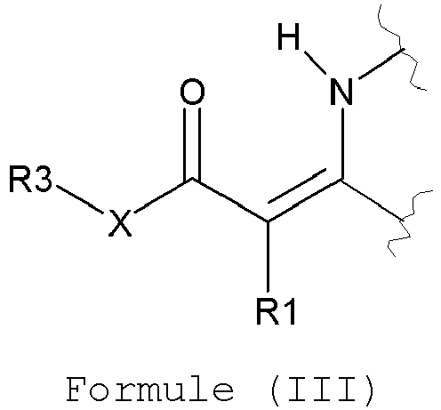 R1 représente de l'hydrogène, un groupe alkyle éventuellement substitué, un groupe cycloalkyle éventuellement substitué, un groupe alkényle éventuellement substitué, un groupe cycloalkényle éventuellement substitué, un groupe alkynyle éventuellement substitué, un groupe aralkyle éventuellement substitué, un groupe alcaryle éventuellement substitué, un groupe aryle éventuellement substitué, un groupe hétéroaryle éventuellement substitué, COR4 ou CN,R2 représente de l'hydrogène, un groupe alkyle éventuellement substitué, un groupe cycloalkyle éventuellement substitué, un groupe alkényle éventuellement substitué, un groupe cycloalkényle éventuellement substitué, un groupe alkynyle éventuellement substitué, un groupe aralkyle éventuellement substitué, un groupe alcaryle éventuellement substitué, un groupe aryle éventuellement substitué, un groupe hétéroaryle éventuellement substitué ou COR4,R1 et R2 peuvent représenter les atomes nécessaires pour former un cycle à 5 à 8 membres,R3 représente un groupe alkyle éventuellement substitué, un groupe cycloalkyle éventuellement substitué, un groupe alkényle éventuellement substitué, un groupe cycloalkényle éventuellement substitué, un groupe alkynyle éventuellement substitué, un groupe aralkyle éventuellement substitué, un groupe alcaryle éventuellement substitué, un groupe aryle éventuellement substitué ou un groupe hétéroaryle éventuellement substitué,R4 représente de l'hydrogène, un groupe alkyle éventuellement substitué, un groupe cycloalkyle éventuellement substitué, un groupe alkényle éventuellement substitué, un groupe cycloalkényle éventuellement substitué, un groupe alkynyle éventuellement substitué, un groupe aralkyle éventuellement substitué, un groupe alcaryle éventuellement substitué, un groupe aryle éventuellement substitué, un groupe hétéroaryle éventuellement substitué, OR5 ou NR6R7,R5 représente un groupe alkyle éventuellement substitué, un groupe cycloalkyle éventuellement substitué, un groupe alkényle éventuellement substitué, un groupe cycloalkényle éventuellement substitué, un groupe alkynyle éventuellement substitué, un groupe aralkyle éventuellement substitué, un groupe alcaryle éventuellement substitué, un groupe aryle éventuellement substitué ou un groupe hétéroaryle éventuellement substitué,R6 et R7 représentent, l'un indépendamment de l'autre, de l'hydrogène, un groupe alkyle éventuellement substitué, un groupe cycloalkyle éventuellement substitué, un groupe alkényle éventuellement substitué, un groupe cycloalkényle éventuellement substitué, un groupe alkynyle éventuellement substitué, un groupe aralkyle éventuellement substitué, un groupe alcaryle éventuellement substitué, un groupe aryle éventuellement substitué ou un groupe hétéroaryle éventuellement substitué ou R6 et R7 peuvent représenter les atomes nécessaires pour former un cycle à 5 à 8 membres,X représente O, NR8 ou CR9R10,R8, R9 et R10 représentent, l'un indépendamment de l'autre, de l'hydrogène, un groupe alkyle éventuellement substitué, un groupe cycloalkyle éventuellement substitué, un groupe alkényle éventuellement substitué, un groupe cycloalkényle éventuellement substitué, un groupe alkynyle éventuellement substitué, un groupe aralkyle éventuellement substitué, un groupe alcaryle éventuellement substitué, un groupe aryle éventuellement substitué ou un groupe hétéroaryle éventuellement substitué,R8 et R3 peuvent représenter les atomes nécessaires pour former un cycle à 5 à 8 membres,une combinaison quelconque de R3, R9 et R10 peut représenter les atomes nécessaires pour former un cycle à 5 à 8 membres.
 - Précurseur de plaque d'impression selon la revendication 1, caractérisé en ce que X représente O.
- Précurseur de plaque d'impression selon les revendications 1 ou 2, caractérisé en ce que la résine a une partie répondant à la Formule I.
- Précurseur de plaque d'impression selon les revendications 1 à 3, caractérisé en ce que R1 et R2 représentent, l'un indépendamment de l'autre, de l'hydrogène ou un groupe alkyle éventuellement substitué, un groupe aryle éventuellement substitué ou un groupe hétéroaryle éventuellement substitué.
- Précurseur de plaque d'impression selon l'une quelconque des revendications précédentes, caractérisé en ce que les particules de vitrimère vinylogues ont une structure de coeur-enveloppe où l'enveloppe contient la résine.
- Précurseur de plaque d'impression selon l'une quelconque des revendications précédentes, caractérisé en ce que le revêtement contient en outre un colorant absorbant les rayons infrarouges.
- Précurseur de plaque d'impression selon la revendication 6, caractérisé en ce que le colorant absorbant les rayons infrarouges est contenu dans le coeur des particules de vitrimère vinylogues.
- Précurseur de plaque d'impression selon les revendications 6 ou 7, caractérisé en ce que le colorant absorbant les rayons infrarouges répond à la Formule suivante:
 Ar1 et Ar2 représentent, l'un indépendamment de l'autre, un groupe hydrocarbure aromatique éventuellement substitué ou un groupe hydrocarbure aromatique comprenant un cycle benzénique annélé éventuellement substituéW1 et W2 représentent, l'un indépendamment de l'autre, un atome de soufre ou un groupe -CM10M11-, où M10 et M11 représentent, l'un indépendamment de l'autre, un groupe hydrocarbure aliphatique éventuellement substitué ou un groupe (hétéro)aryle éventuellement substitué ou où M10 et M11 comprennent ensemble les atomes nécessaires pour former une structure cyclique,M1 et M2 comprennent ensemble les atomes nécessaires pour former une structure cyclique éventuellement substituée, de préférence M1 et M2 comprennent ensemble les atomes nécessaires pour former un cycle à 5 membres éventuellement substitué,M3 et M4 représentent, l'un indépendamment de l'autre, un groupe hydrocarbure aliphatique éventuellement substitué, M5, M6, M7 et M8 représentent, l'un indépendamment de l'autre, de l'hydrogène, un halogène ou un groupe hydrocarbure aliphatique éventuellement substitué,M9 représente un halogène, un groupe hydrocarbure aliphatique éventuellement substitué, un groupe (hétéro)aryle éventuellement substitué, -NR1R2, -NR4-CO-R6, -NR4-SO2-R4 ou -NR1-SO-R5, où R1 et R2 représentent, l'un indépendamment de l'autre, de l'hydrogène, un groupe hydrocarbure aliphatique éventuellement substitué ou un groupe (hétéro)aryle éventuellement substitué,R4 et R6 représentent, l'un indépendamment de l'autre, -OR7, -NR8R9 ou -CF3, où R7 représente un groupe (hétéro)aryle éventuellement substitué ou un groupe hydrocarbure aliphatique éventuellement substitué et R8 et R9 représentent, l'un indépendamment de l'autre, de l'hydrogène, un groupe hydrocarbure aliphatique éventuellement substitué ou un groupe (hétéro)aryle éventuellement substitué ou où R8 et R9 comprennent ensemble les atomes nécessaires pour former une structure cyclique,R5 représente de l'hydrogène, un groupe hydrocarbure aliphatique éventuellement substitué, SO3 -, -COOR10 ou un groupe (hétéro)aryle éventuellement substitué, où R10 représente un groupe (hétéro)aryle éventuellement substitué ou un groupe hydrocarbure aliphatique, etcaractérisé en ce que le colorant absorbant les rayons infrarouges peut contenir un ou plusieurs contre-ions afin d'obtenir une molécule électriquement neutre.
 - Précurseur de plaque d'impression selon l'une quelconque des revendications précédentes, caractérisé en ce que le revêtement contient en outre un composé capable de former une image directement visible.
- Procédé pour la fabrication d'une plaque d'impression comprenant les étapes consistant à:- exposer sous forme d'image à de la chaleur et/ou à du rayonnement infrarouge le précurseur de plaque d'impression tel que défini selon l'une quelconque des revendications précédentes,- développer le précurseur exposé.
- Procédé selon la revendication 10, caractérisé en ce que l'étape de développement est une étape hors presse lors de laquelle le précurseur est traité avec une solution révélatrice, permettant d'éliminer les zones non exposées du support.
- Procédé selon la revendication 11, caractérisé en ce que la solution révélatrice contient une solution de gommage qui permet de développer et de gommer le précurseur en une seule étape, ou de l'eau.
- Procédé selon la revendication 10, caractérisé en ce que l'étape de développement est effectuée en serrant le précurseur exposé sur un cylindre porte-plaque d'une machine à imprimer lithographique et en faisant tourner le cylindre porte-plaque pendant qu'un liquide de mouillage et/ou de l'encre est (sont) appliqué(e)(s) sur ledit précurseur.
- Procédé selon les revendications 10 à 13, caractérisé en ce que le rayonnement infrarouge est compris entre 70 mJ/m2 et 180 mJ/m2.
Priority Applications (4)
| Application Number | Priority Date | Filing Date | Title |
|---|---|---|---|
| EP17185082.9A EP3441223B1 (fr) | 2017-08-07 | 2017-08-07 | Précurseur de plaque d'impression lithographique |
| US16/636,042 US11376836B2 (en) | 2017-08-07 | 2018-07-12 | Lithographic printing plate precursor |
| CN201880051490.4A CN110914059B (zh) | 2017-08-07 | 2018-07-12 | 平版印刷版前体 |
| PCT/EP2018/068971 WO2019029945A1 (fr) | 2017-08-07 | 2018-07-12 | Précurseur de plaque d'impression lithographique |
Applications Claiming Priority (1)
| Application Number | Priority Date | Filing Date | Title |
|---|---|---|---|
| EP17185082.9A EP3441223B1 (fr) | 2017-08-07 | 2017-08-07 | Précurseur de plaque d'impression lithographique |
Publications (2)
| Publication Number | Publication Date |
|---|---|
| EP3441223A1 EP3441223A1 (fr) | 2019-02-13 |
| EP3441223B1 true EP3441223B1 (fr) | 2024-02-21 |
Family
ID=59569166
Family Applications (1)
| Application Number | Title | Priority Date | Filing Date |
|---|---|---|---|
| EP17185082.9A Active EP3441223B1 (fr) | 2017-08-07 | 2017-08-07 | Précurseur de plaque d'impression lithographique |
Country Status (4)
| Country | Link |
|---|---|
| US (1) | US11376836B2 (fr) |
| EP (1) | EP3441223B1 (fr) |
| CN (1) | CN110914059B (fr) |
| WO (1) | WO2019029945A1 (fr) |
Families Citing this family (4)
| Publication number | Priority date | Publication date | Assignee | Title |
|---|---|---|---|---|
| US12252622B2 (en) | 2018-09-27 | 2025-03-18 | Agfa-Gevaert Nv | Aqueous dispersion of resin particles |
| US12359080B2 (en) | 2018-12-03 | 2025-07-15 | Agfa-Gevaert Nv | Aqueous dispersion of capsules |
| WO2020114819A1 (fr) * | 2018-12-05 | 2020-06-11 | Agfa-Gevaert Nv | Dispersion aqueuse de particules de résine |
| CN111439024A (zh) * | 2020-04-07 | 2020-07-24 | 江苏悦达印刷有限公司 | 一种新型印刷保留版机 |
Family Cites Families (56)
| Publication number | Priority date | Publication date | Assignee | Title |
|---|---|---|---|---|
| US4045232A (en) | 1973-11-12 | 1977-08-30 | Topar Products Corporation | Printing ink composition |
| US4981517A (en) | 1989-06-12 | 1991-01-01 | Desanto Jr Ronald F | Printing ink emulsion |
| JPH07114175A (ja) * | 1993-10-15 | 1995-05-02 | Konica Corp | 画像形成材料 |
| EP0770495B1 (fr) | 1995-10-24 | 2002-06-19 | Agfa-Gevaert | Procédé pour la fabrication d'une plaque lithographique avec développement sur presse |
| EP0770494B1 (fr) | 1995-10-24 | 2000-05-24 | Agfa-Gevaert N.V. | Procédé pour la fabrication d'une plaque lithographique avec développement sur presse |
| EP1092555B1 (fr) | 1995-10-24 | 2002-08-21 | Agfa-Gevaert | Procédé pour la fabrication d'une plaque lithographique avec développement sur presse |
| EP0770496B1 (fr) | 1995-10-24 | 2002-03-13 | Agfa-Gevaert | Appareil pour la fabrication d'une plaque lithographique avec développement sur presse |
| ES2114521T3 (es) | 1996-04-23 | 2000-01-16 | Kodak Polychrome Graphics Co | Precursor de la forma para impresion litografica y su utilizacion en la formacion de imagenes por calor. |
| JP3814961B2 (ja) | 1996-08-06 | 2006-08-30 | 三菱化学株式会社 | ポジ型感光性印刷版 |
| DE69731515T2 (de) | 1996-08-14 | 2005-10-27 | Mitsubishi Paper Mills Limited | Gerät zur Behandlung fotoempfindlichen Materials |
| EP0851299B1 (fr) | 1996-12-26 | 2000-10-25 | Mitsubishi Chemical Corporation | Plaque d'impression lithographique photosensible |
| DE19834746A1 (de) | 1998-08-01 | 2000-02-03 | Agfa Gevaert Ag | Strahlungsempfindliches Gemisch mit IR-absorbierenden, betainischen oder betainisch-anionischen Cyaninfarbstoffen und damit hergestelltes Aufzeichnungsmaterial |
| BR9915407A (pt) | 1998-11-16 | 2001-07-24 | Mitsubishi Chem Corp | Placa de impressão litográfica fotossensìvel positiva sensìvel a raios infravermelhos proximos; método de produzila e método para formar uma imagem positiva |
| US6140392A (en) | 1998-11-30 | 2000-10-31 | Flint Ink Corporation | Printing inks |
| EP1025992B1 (fr) | 1999-02-02 | 2003-07-23 | Agfa-Gevaert | Procédé de fabrication de plaques d'impression travaillant en positif |
| JP3996305B2 (ja) | 1999-02-15 | 2007-10-24 | 富士フイルム株式会社 | ポジ型平版印刷用材料 |
| DE60037951T2 (de) | 1999-05-21 | 2009-02-05 | Fujifilm Corp. | Fotoempfindliche Zusammensetzung und Flachdruckplatte, die diese Zusammensetzung verwendet |
| US6558873B1 (en) | 1999-10-05 | 2003-05-06 | Fuji Photo Film Co., Ltd. | Lithographic printing plate precursor |
| ATE259301T1 (de) | 1999-10-19 | 2004-02-15 | Fuji Photo Film Co Ltd | Fotoempfindliche zusammensetzung und flachdruckplatte, die diese zusammensetzung verwendet |
| DE10063216B8 (de) | 1999-12-20 | 2013-05-16 | Mitsubishi Paper Mills Limited | Vorrichtung zum Bearbeiten von fotosensiblem Material |
| JP4266077B2 (ja) | 2001-03-26 | 2009-05-20 | 富士フイルム株式会社 | 平版印刷版原版及び平版印刷方法 |
| US6739260B2 (en) * | 2001-05-17 | 2004-05-25 | Agfa-Gevaert | Method for the preparation of a negative working printing plate |
| JP2003107720A (ja) * | 2001-09-28 | 2003-04-09 | Fuji Photo Film Co Ltd | 平版印刷版用原版 |
| EP1342568B1 (fr) | 2002-03-06 | 2005-10-12 | Agfa-Gevaert N.V. | Procédé de développement d'un précurseur thermosensible pour une plaque lithographique avec une solution de gomme |
| EP1356926B1 (fr) | 2002-04-26 | 2008-01-16 | Agfa Graphics N.V. | Précurseur pour plaque lithographique de type négatif, comprenant un support lisse d'aluminium |
| DE50204080D1 (de) | 2002-04-29 | 2005-10-06 | Agfa Gevaert Nv | Strahlungsempfindliches Gemisch, damit hergestelltes Aufzeichnungsmaterial, und Verfahren zur Herstellung einer Druckplatte |
| EP1477511A1 (fr) * | 2003-05-15 | 2004-11-17 | DSM IP Assets B.V. | Compositions à base de polyène et de polythiol durcissables sous irradiation |
| JP2005014348A (ja) | 2003-06-25 | 2005-01-20 | Fuji Photo Film Co Ltd | 平版印刷版原版及び平版印刷方法 |
| JP4418714B2 (ja) | 2003-07-10 | 2010-02-24 | 富士フイルム株式会社 | 平版印刷版原版及び平版印刷方法 |
| DE602004030519D1 (de) | 2003-07-22 | 2011-01-27 | Fujifilm Corp | Flachdruckplattenvorläufer und lithographisches Druckverfahren |
| US6992688B2 (en) | 2004-01-28 | 2006-01-31 | Eastman Kodak Company | Method for developing multilayer imageable elements |
| EP1916101B1 (fr) | 2003-08-13 | 2009-11-18 | Agfa Graphics N.V. | Procédé de post-cuisson d'une plaque d'impression lithographique |
| JP2005067006A (ja) | 2003-08-22 | 2005-03-17 | Fuji Photo Film Co Ltd | 平版印刷版の製版方法、平版印刷方法および平版印刷原版 |
| JP4815113B2 (ja) | 2003-09-24 | 2011-11-16 | 富士フイルム株式会社 | 平版印刷版原版および平版印刷方法 |
| JP4644458B2 (ja) | 2003-09-30 | 2011-03-02 | 富士フイルム株式会社 | 平版印刷版原版および平版印刷方法 |
| CN100537260C (zh) * | 2003-10-25 | 2009-09-09 | 爱克发印艺公司 | 含有光滑铝载体的负性热平版印刷的印刷版前体 |
| US20050170282A1 (en) | 2004-01-23 | 2005-08-04 | Fuji Photo Film Co., Ltd. | Lithographic printing plate precursor and lithographic printing method |
| JP2007538279A (ja) | 2004-05-19 | 2007-12-27 | アグファ・ゲヴェルト・ナームロゼ・ベンノートチャップ | 感光性ポリマー印刷版の製造方法 |
| ATE424299T1 (de) | 2004-07-08 | 2009-03-15 | Agfa Graphics Nv | Verfahren zur herstellung einer negativarbeitenden, wärmeempfindlichen, lithographischen druckplattenvorstufe |
| EP1614539B1 (fr) | 2004-07-08 | 2008-09-17 | Agfa Graphics N.V. | Procédé de production d'une plaque d'impression lithographique |
| WO2006005688A1 (fr) | 2004-07-08 | 2006-01-19 | Agfa-Gevaert | Procede destine a produire un precurseur de planche d'impression lithographique sensible a la chaleur avec copie au negatif |
| EP1614540B1 (fr) | 2004-07-08 | 2008-09-17 | Agfa Graphics N.V. | Procédé de production d'une plaque d'impression lithographique |
| ATE391014T1 (de) | 2005-06-21 | 2008-04-15 | Agfa Graphics Nv | Wärmeempfindliches bildaufzeichnungselement |
| DE602005026136D1 (de) | 2005-11-18 | 2011-03-10 | Agfa Graphics Nv | Verfahren zur Herstellung einer Lithografiedruckform |
| EP1788434B2 (fr) | 2005-11-18 | 2019-01-02 | Agfa Nv | Procédé de fabrication d'une plaque d'impression lithographique |
| EP2772805A1 (fr) | 2005-11-18 | 2014-09-03 | Agfa Graphics Nv | Procédé de fabrication d'une plaque d'impression lithographique |
| EP1788431B1 (fr) | 2005-11-18 | 2009-01-28 | Agfa Graphics N.V. | Procédé de fabrication d'une plaque d'impression lithographique |
| EP1843203A1 (fr) | 2006-04-03 | 2007-10-10 | Agfa Graphics N.V. | Procédé de fabrication d'une plaque d'impression photopolymère |
| EP1974911B1 (fr) * | 2007-03-27 | 2010-05-19 | Agfa Graphics N.V. | Procédé de fabrication d'une plaque d'impression lithographique |
| US8415087B2 (en) | 2007-11-16 | 2013-04-09 | Agfa Graphics Nv | Method of making a lithographic printing plate |
| JP5481794B2 (ja) * | 2008-03-25 | 2014-04-23 | Jsr株式会社 | レーザー加工用成形品の製造方法、レーザー加工用成形品、及びフレキソ印刷版 |
| JP5444933B2 (ja) | 2008-08-29 | 2014-03-19 | 富士フイルム株式会社 | ネガ型平版印刷版原版及びそれを用いる平版印刷方法 |
| US9329479B2 (en) | 2012-06-05 | 2016-05-03 | Agfa Graphics Nv | Lithographic printing plate precusor |
| JP2015030122A (ja) * | 2013-07-31 | 2015-02-16 | 富士フイルム株式会社 | フレキソ印刷版及びその製版方法、レーザー彫刻型フレキソ印刷版用リンス液、並びに、レーザー彫刻型フレキソ印刷版製版キット |
| FR3020496A1 (fr) * | 2014-04-24 | 2015-10-30 | Arkema France | Utilisation d'une composition de resine thermodurcissable de type vitrimere pour la fabrication de pieces d'isolation electrique |
| EP3233978B1 (fr) | 2014-12-19 | 2021-03-03 | Universiteit Gent | Compositions comprenant un réseau polymère |
-
2017
- 2017-08-07 EP EP17185082.9A patent/EP3441223B1/fr active Active
-
2018
- 2018-07-12 CN CN201880051490.4A patent/CN110914059B/zh active Active
- 2018-07-12 WO PCT/EP2018/068971 patent/WO2019029945A1/fr not_active Ceased
- 2018-07-12 US US16/636,042 patent/US11376836B2/en active Active
Also Published As
| Publication number | Publication date |
|---|---|
| CN110914059A (zh) | 2020-03-24 |
| US20210354439A1 (en) | 2021-11-18 |
| CN110914059B (zh) | 2022-02-08 |
| US11376836B2 (en) | 2022-07-05 |
| WO2019029945A1 (fr) | 2019-02-14 |
| EP3441223A1 (fr) | 2019-02-13 |
Similar Documents
| Publication | Publication Date | Title |
|---|---|---|
| EP1940620B1 (fr) | Précurseur de plaque d'impression lithographique thermosensible et négative | |
| CN1984778B (zh) | 阴片热敏平版印刷版前体的制备方法 | |
| US8216769B2 (en) | Negative working, heat sensitive lithographic printing plate precursor | |
| WO2019179996A1 (fr) | Précurseur de plaque d'impression lithographique | |
| EP1614538A2 (fr) | Procédé pour la fabrication d'un précurseur de type négatif d'une plaque d'impression lithographique thermosensible | |
| EP1614540A1 (fr) | Procédé de production d'une plaque d'impression lithographique | |
| US11376836B2 (en) | Lithographic printing plate precursor | |
| EP3431290A1 (fr) | Précurseur de plaque d'impression lithographique | |
| EP2871057B1 (fr) | Précurseur de plaque d'impression lithographique thermosensible à action négative | |
| EP1777067B1 (fr) | Procédé pour réaliser un précurseur de plaque d'impression lithographique | |
| CN101652251A (zh) | 制造平版印刷版前体的方法 | |
| EP1904305B1 (fr) | Procédé de fabrication d'un précurseur de plaque d'impression lithographique en négatif | |
| EP1914069B1 (fr) | Précurseur de plaque d'impression lithographique thermosensible à action négative | |
| EP3239184A1 (fr) | Particules de polymère thermoplastique et précurseur de plaque d'impression lithographique | |
| CN101646567B (zh) | 制造平版印刷版前体的方法 | |
| CN1690850B (zh) | 负性的热敏平版印版母体 | |
| WO2019076584A1 (fr) | Précurseur de plaque d'impression lithographique | |
| WO2009030279A1 (fr) | Précurseur pour plaque d'impression lithographique thermosensible | |
| EP1604818B1 (fr) | Précurseur de plaque d'impression lithographique, sensible à la chaleur et travaillant en négatif | |
| EP3170662B1 (fr) | Précurseur de plaque d'impression lithographique |
Legal Events
| Date | Code | Title | Description |
|---|---|---|---|
| PUAI | Public reference made under article 153(3) epc to a published international application that has entered the european phase |
Free format text: ORIGINAL CODE: 0009012 |
|
| STAA | Information on the status of an ep patent application or granted ep patent |
Free format text: STATUS: THE APPLICATION HAS BEEN PUBLISHED |
|
| AK | Designated contracting states |
Kind code of ref document: A1 Designated state(s): AL AT BE BG CH CY CZ DE DK EE ES FI FR GB GR HR HU IE IS IT LI LT LU LV MC MK MT NL NO PL PT RO RS SE SI SK SM TR |
|
| AX | Request for extension of the european patent |
Extension state: BA ME |
|
| STAA | Information on the status of an ep patent application or granted ep patent |
Free format text: STATUS: REQUEST FOR EXAMINATION WAS MADE |
|
| 17P | Request for examination filed |
Effective date: 20190813 |
|
| RBV | Designated contracting states (corrected) |
Designated state(s): AL AT BE BG CH CY CZ DE DK EE ES FI FR GB GR HR HU IE IS IT LI LT LU LV MC MK MT NL NO PL PT RO RS SE SI SK SM TR |
|
| STAA | Information on the status of an ep patent application or granted ep patent |
Free format text: STATUS: EXAMINATION IS IN PROGRESS |
|
| 17Q | First examination report despatched |
Effective date: 20210922 |
|
| RAP3 | Party data changed (applicant data changed or rights of an application transferred) |
Owner name: AGFA OFFSET BV |
|
| RAP3 | Party data changed (applicant data changed or rights of an application transferred) |
Owner name: ECO3 BV |
|
| GRAP | Despatch of communication of intention to grant a patent |
Free format text: ORIGINAL CODE: EPIDOSNIGR1 |
|
| STAA | Information on the status of an ep patent application or granted ep patent |
Free format text: STATUS: GRANT OF PATENT IS INTENDED |
|
| INTG | Intention to grant announced |
Effective date: 20231027 |
|
| GRAS | Grant fee paid |
Free format text: ORIGINAL CODE: EPIDOSNIGR3 |
|
| GRAA | (expected) grant |
Free format text: ORIGINAL CODE: 0009210 |
|
| STAA | Information on the status of an ep patent application or granted ep patent |
Free format text: STATUS: THE PATENT HAS BEEN GRANTED |
|
| AK | Designated contracting states |
Kind code of ref document: B1 Designated state(s): AL AT BE BG CH CY CZ DE DK EE ES FI FR GB GR HR HU IE IS IT LI LT LU LV MC MK MT NL NO PL PT RO RS SE SI SK SM TR |
|
| REG | Reference to a national code |
Ref country code: GB Ref legal event code: FG4D |
|
| REG | Reference to a national code |
Ref country code: CH Ref legal event code: EP |
|
| REG | Reference to a national code |
Ref country code: DE Ref legal event code: R096 Ref document number: 602017079299 Country of ref document: DE |
|
| REG | Reference to a national code |
Ref country code: IE Ref legal event code: FG4D |
|
| REG | Reference to a national code |
Ref country code: LT Ref legal event code: MG9D |
|
| REG | Reference to a national code |
Ref country code: NL Ref legal event code: MP Effective date: 20240221 |
|
| PG25 | Lapsed in a contracting state [announced via postgrant information from national office to epo] |
Ref country code: IS Free format text: LAPSE BECAUSE OF FAILURE TO SUBMIT A TRANSLATION OF THE DESCRIPTION OR TO PAY THE FEE WITHIN THE PRESCRIBED TIME-LIMIT Effective date: 20240621 |
|
| PG25 | Lapsed in a contracting state [announced via postgrant information from national office to epo] |
Ref country code: LT Free format text: LAPSE BECAUSE OF FAILURE TO SUBMIT A TRANSLATION OF THE DESCRIPTION OR TO PAY THE FEE WITHIN THE PRESCRIBED TIME-LIMIT Effective date: 20240221 |
|
| PG25 | Lapsed in a contracting state [announced via postgrant information from national office to epo] |
Ref country code: GR Free format text: LAPSE BECAUSE OF FAILURE TO SUBMIT A TRANSLATION OF THE DESCRIPTION OR TO PAY THE FEE WITHIN THE PRESCRIBED TIME-LIMIT Effective date: 20240522 |
|
| REG | Reference to a national code |
Ref country code: AT Ref legal event code: MK05 Ref document number: 1658806 Country of ref document: AT Kind code of ref document: T Effective date: 20240221 |
|
| PG25 | Lapsed in a contracting state [announced via postgrant information from national office to epo] |
Ref country code: RS Free format text: LAPSE BECAUSE OF FAILURE TO SUBMIT A TRANSLATION OF THE DESCRIPTION OR TO PAY THE FEE WITHIN THE PRESCRIBED TIME-LIMIT Effective date: 20240521 Ref country code: NL Free format text: LAPSE BECAUSE OF FAILURE TO SUBMIT A TRANSLATION OF THE DESCRIPTION OR TO PAY THE FEE WITHIN THE PRESCRIBED TIME-LIMIT Effective date: 20240221 Ref country code: HR Free format text: LAPSE BECAUSE OF FAILURE TO SUBMIT A TRANSLATION OF THE DESCRIPTION OR TO PAY THE FEE WITHIN THE PRESCRIBED TIME-LIMIT Effective date: 20240221 |
|
| PG25 | Lapsed in a contracting state [announced via postgrant information from national office to epo] |
Ref country code: ES Free format text: LAPSE BECAUSE OF FAILURE TO SUBMIT A TRANSLATION OF THE DESCRIPTION OR TO PAY THE FEE WITHIN THE PRESCRIBED TIME-LIMIT Effective date: 20240221 |
|
| PG25 | Lapsed in a contracting state [announced via postgrant information from national office to epo] |
Ref country code: AT Free format text: LAPSE BECAUSE OF FAILURE TO SUBMIT A TRANSLATION OF THE DESCRIPTION OR TO PAY THE FEE WITHIN THE PRESCRIBED TIME-LIMIT Effective date: 20240221 |
|
| PG25 | Lapsed in a contracting state [announced via postgrant information from national office to epo] |
Ref country code: RS Free format text: LAPSE BECAUSE OF FAILURE TO SUBMIT A TRANSLATION OF THE DESCRIPTION OR TO PAY THE FEE WITHIN THE PRESCRIBED TIME-LIMIT Effective date: 20240521 Ref country code: NO Free format text: LAPSE BECAUSE OF FAILURE TO SUBMIT A TRANSLATION OF THE DESCRIPTION OR TO PAY THE FEE WITHIN THE PRESCRIBED TIME-LIMIT Effective date: 20240521 Ref country code: NL Free format text: LAPSE BECAUSE OF FAILURE TO SUBMIT A TRANSLATION OF THE DESCRIPTION OR TO PAY THE FEE WITHIN THE PRESCRIBED TIME-LIMIT Effective date: 20240221 Ref country code: LT Free format text: LAPSE BECAUSE OF FAILURE TO SUBMIT A TRANSLATION OF THE DESCRIPTION OR TO PAY THE FEE WITHIN THE PRESCRIBED TIME-LIMIT Effective date: 20240221 Ref country code: IS Free format text: LAPSE BECAUSE OF FAILURE TO SUBMIT A TRANSLATION OF THE DESCRIPTION OR TO PAY THE FEE WITHIN THE PRESCRIBED TIME-LIMIT Effective date: 20240621 Ref country code: HR Free format text: LAPSE BECAUSE OF FAILURE TO SUBMIT A TRANSLATION OF THE DESCRIPTION OR TO PAY THE FEE WITHIN THE PRESCRIBED TIME-LIMIT Effective date: 20240221 Ref country code: GR Free format text: LAPSE BECAUSE OF FAILURE TO SUBMIT A TRANSLATION OF THE DESCRIPTION OR TO PAY THE FEE WITHIN THE PRESCRIBED TIME-LIMIT Effective date: 20240522 Ref country code: FI Free format text: LAPSE BECAUSE OF FAILURE TO SUBMIT A TRANSLATION OF THE DESCRIPTION OR TO PAY THE FEE WITHIN THE PRESCRIBED TIME-LIMIT Effective date: 20240221 Ref country code: ES Free format text: LAPSE BECAUSE OF FAILURE TO SUBMIT A TRANSLATION OF THE DESCRIPTION OR TO PAY THE FEE WITHIN THE PRESCRIBED TIME-LIMIT Effective date: 20240221 Ref country code: BG Free format text: LAPSE BECAUSE OF FAILURE TO SUBMIT A TRANSLATION OF THE DESCRIPTION OR TO PAY THE FEE WITHIN THE PRESCRIBED TIME-LIMIT Effective date: 20240221 Ref country code: AT Free format text: LAPSE BECAUSE OF FAILURE TO SUBMIT A TRANSLATION OF THE DESCRIPTION OR TO PAY THE FEE WITHIN THE PRESCRIBED TIME-LIMIT Effective date: 20240221 |
|
| PG25 | Lapsed in a contracting state [announced via postgrant information from national office to epo] |
Ref country code: PL Free format text: LAPSE BECAUSE OF FAILURE TO SUBMIT A TRANSLATION OF THE DESCRIPTION OR TO PAY THE FEE WITHIN THE PRESCRIBED TIME-LIMIT Effective date: 20240221 Ref country code: PT Free format text: LAPSE BECAUSE OF FAILURE TO SUBMIT A TRANSLATION OF THE DESCRIPTION OR TO PAY THE FEE WITHIN THE PRESCRIBED TIME-LIMIT Effective date: 20240621 |
|
| PG25 | Lapsed in a contracting state [announced via postgrant information from national office to epo] |
Ref country code: SE Free format text: LAPSE BECAUSE OF FAILURE TO SUBMIT A TRANSLATION OF THE DESCRIPTION OR TO PAY THE FEE WITHIN THE PRESCRIBED TIME-LIMIT Effective date: 20240221 Ref country code: PT Free format text: LAPSE BECAUSE OF FAILURE TO SUBMIT A TRANSLATION OF THE DESCRIPTION OR TO PAY THE FEE WITHIN THE PRESCRIBED TIME-LIMIT Effective date: 20240621 Ref country code: PL Free format text: LAPSE BECAUSE OF FAILURE TO SUBMIT A TRANSLATION OF THE DESCRIPTION OR TO PAY THE FEE WITHIN THE PRESCRIBED TIME-LIMIT Effective date: 20240221 Ref country code: LV Free format text: LAPSE BECAUSE OF FAILURE TO SUBMIT A TRANSLATION OF THE DESCRIPTION OR TO PAY THE FEE WITHIN THE PRESCRIBED TIME-LIMIT Effective date: 20240221 |
|
| PG25 | Lapsed in a contracting state [announced via postgrant information from national office to epo] |
Ref country code: DK Free format text: LAPSE BECAUSE OF FAILURE TO SUBMIT A TRANSLATION OF THE DESCRIPTION OR TO PAY THE FEE WITHIN THE PRESCRIBED TIME-LIMIT Effective date: 20240221 |
|
| PG25 | Lapsed in a contracting state [announced via postgrant information from national office to epo] |
Ref country code: SM Free format text: LAPSE BECAUSE OF FAILURE TO SUBMIT A TRANSLATION OF THE DESCRIPTION OR TO PAY THE FEE WITHIN THE PRESCRIBED TIME-LIMIT Effective date: 20240221 |
|
| PG25 | Lapsed in a contracting state [announced via postgrant information from national office to epo] |
Ref country code: CZ Free format text: LAPSE BECAUSE OF FAILURE TO SUBMIT A TRANSLATION OF THE DESCRIPTION OR TO PAY THE FEE WITHIN THE PRESCRIBED TIME-LIMIT Effective date: 20240221 Ref country code: EE Free format text: LAPSE BECAUSE OF FAILURE TO SUBMIT A TRANSLATION OF THE DESCRIPTION OR TO PAY THE FEE WITHIN THE PRESCRIBED TIME-LIMIT Effective date: 20240221 |
|
| PG25 | Lapsed in a contracting state [announced via postgrant information from national office to epo] |
Ref country code: SK Free format text: LAPSE BECAUSE OF FAILURE TO SUBMIT A TRANSLATION OF THE DESCRIPTION OR TO PAY THE FEE WITHIN THE PRESCRIBED TIME-LIMIT Effective date: 20240221 |
|
| PG25 | Lapsed in a contracting state [announced via postgrant information from national office to epo] |
Ref country code: SM Free format text: LAPSE BECAUSE OF FAILURE TO SUBMIT A TRANSLATION OF THE DESCRIPTION OR TO PAY THE FEE WITHIN THE PRESCRIBED TIME-LIMIT Effective date: 20240221 Ref country code: SK Free format text: LAPSE BECAUSE OF FAILURE TO SUBMIT A TRANSLATION OF THE DESCRIPTION OR TO PAY THE FEE WITHIN THE PRESCRIBED TIME-LIMIT Effective date: 20240221 Ref country code: RO Free format text: LAPSE BECAUSE OF FAILURE TO SUBMIT A TRANSLATION OF THE DESCRIPTION OR TO PAY THE FEE WITHIN THE PRESCRIBED TIME-LIMIT Effective date: 20240221 Ref country code: EE Free format text: LAPSE BECAUSE OF FAILURE TO SUBMIT A TRANSLATION OF THE DESCRIPTION OR TO PAY THE FEE WITHIN THE PRESCRIBED TIME-LIMIT Effective date: 20240221 Ref country code: DK Free format text: LAPSE BECAUSE OF FAILURE TO SUBMIT A TRANSLATION OF THE DESCRIPTION OR TO PAY THE FEE WITHIN THE PRESCRIBED TIME-LIMIT Effective date: 20240221 Ref country code: CZ Free format text: LAPSE BECAUSE OF FAILURE TO SUBMIT A TRANSLATION OF THE DESCRIPTION OR TO PAY THE FEE WITHIN THE PRESCRIBED TIME-LIMIT Effective date: 20240221 |
|
| REG | Reference to a national code |
Ref country code: DE Ref legal event code: R097 Ref document number: 602017079299 Country of ref document: DE |
|
| PG25 | Lapsed in a contracting state [announced via postgrant information from national office to epo] |
Ref country code: IT Free format text: LAPSE BECAUSE OF FAILURE TO SUBMIT A TRANSLATION OF THE DESCRIPTION OR TO PAY THE FEE WITHIN THE PRESCRIBED TIME-LIMIT Effective date: 20240221 |
|
| PLBE | No opposition filed within time limit |
Free format text: ORIGINAL CODE: 0009261 |
|
| STAA | Information on the status of an ep patent application or granted ep patent |
Free format text: STATUS: NO OPPOSITION FILED WITHIN TIME LIMIT |
|
| PG25 | Lapsed in a contracting state [announced via postgrant information from national office to epo] |
Ref country code: IT Free format text: LAPSE BECAUSE OF FAILURE TO SUBMIT A TRANSLATION OF THE DESCRIPTION OR TO PAY THE FEE WITHIN THE PRESCRIBED TIME-LIMIT Effective date: 20240221 |
|
| 26N | No opposition filed |
Effective date: 20241122 |
|
| REG | Reference to a national code |
Ref country code: CH Ref legal event code: PL |
|
| PG25 | Lapsed in a contracting state [announced via postgrant information from national office to epo] |
Ref country code: LU Free format text: LAPSE BECAUSE OF NON-PAYMENT OF DUE FEES Effective date: 20240807 |
|
| PG25 | Lapsed in a contracting state [announced via postgrant information from national office to epo] |
Ref country code: SI Free format text: LAPSE BECAUSE OF FAILURE TO SUBMIT A TRANSLATION OF THE DESCRIPTION OR TO PAY THE FEE WITHIN THE PRESCRIBED TIME-LIMIT Effective date: 20240221 Ref country code: CH Free format text: LAPSE BECAUSE OF NON-PAYMENT OF DUE FEES Effective date: 20240831 Ref country code: MC Free format text: LAPSE BECAUSE OF FAILURE TO SUBMIT A TRANSLATION OF THE DESCRIPTION OR TO PAY THE FEE WITHIN THE PRESCRIBED TIME-LIMIT Effective date: 20240221 |
|
| REG | Reference to a national code |
Ref country code: BE Ref legal event code: MM Effective date: 20240831 |
|
| PG25 | Lapsed in a contracting state [announced via postgrant information from national office to epo] |
Ref country code: BE Free format text: LAPSE BECAUSE OF NON-PAYMENT OF DUE FEES Effective date: 20240831 |
|
| PG25 | Lapsed in a contracting state [announced via postgrant information from national office to epo] |
Ref country code: IE Free format text: LAPSE BECAUSE OF NON-PAYMENT OF DUE FEES Effective date: 20240807 |
|
| PGFP | Annual fee paid to national office [announced via postgrant information from national office to epo] |
Ref country code: DE Payment date: 20250820 Year of fee payment: 9 |
|
| PGFP | Annual fee paid to national office [announced via postgrant information from national office to epo] |
Ref country code: GB Payment date: 20250821 Year of fee payment: 9 |
|
| PGFP | Annual fee paid to national office [announced via postgrant information from national office to epo] |
Ref country code: FR Payment date: 20250828 Year of fee payment: 9 |
|
| PG25 | Lapsed in a contracting state [announced via postgrant information from national office to epo] |
Ref country code: CY Free format text: LAPSE BECAUSE OF FAILURE TO SUBMIT A TRANSLATION OF THE DESCRIPTION OR TO PAY THE FEE WITHIN THE PRESCRIBED TIME-LIMIT; INVALID AB INITIO Effective date: 20170807 |
|
| PG25 | Lapsed in a contracting state [announced via postgrant information from national office to epo] |
Ref country code: HU Free format text: LAPSE BECAUSE OF FAILURE TO SUBMIT A TRANSLATION OF THE DESCRIPTION OR TO PAY THE FEE WITHIN THE PRESCRIBED TIME-LIMIT; INVALID AB INITIO Effective date: 20170807 |