EP3441216B1 - Dispositif d'utilisation lors de la construction d'une carcasse de pneu d'un pneu radial et procédé de fabrication d'une carcasse pour pneu - Google Patents
Dispositif d'utilisation lors de la construction d'une carcasse de pneu d'un pneu radial et procédé de fabrication d'une carcasse pour pneu Download PDFInfo
- Publication number
- EP3441216B1 EP3441216B1 EP18170958.5A EP18170958A EP3441216B1 EP 3441216 B1 EP3441216 B1 EP 3441216B1 EP 18170958 A EP18170958 A EP 18170958A EP 3441216 B1 EP3441216 B1 EP 3441216B1
- Authority
- EP
- European Patent Office
- Prior art keywords
- carcass
- core
- tyre
- winding drum
- gripper
- Prior art date
- Legal status (The legal status is an assumption and is not a legal conclusion. Google has not performed a legal analysis and makes no representation as to the accuracy of the status listed.)
- Active
Links
Images
Classifications
-
- B—PERFORMING OPERATIONS; TRANSPORTING
- B29—WORKING OF PLASTICS; WORKING OF SUBSTANCES IN A PLASTIC STATE IN GENERAL
- B29D—PRODUCING PARTICULAR ARTICLES FROM PLASTICS OR FROM SUBSTANCES IN A PLASTIC STATE
- B29D30/00—Producing pneumatic or solid tyres or parts thereof
- B29D30/0016—Handling tyres or parts thereof, e.g. supplying, storing, conveying
-
- B—PERFORMING OPERATIONS; TRANSPORTING
- B29—WORKING OF PLASTICS; WORKING OF SUBSTANCES IN A PLASTIC STATE IN GENERAL
- B29D—PRODUCING PARTICULAR ARTICLES FROM PLASTICS OR FROM SUBSTANCES IN A PLASTIC STATE
- B29D30/00—Producing pneumatic or solid tyres or parts thereof
- B29D30/06—Pneumatic tyres or parts thereof (e.g. produced by casting, moulding, compression moulding, injection moulding, centrifugal casting)
- B29D30/08—Building tyres
- B29D30/20—Building tyres by the flat-tyre method, i.e. building on cylindrical drums
- B29D30/24—Drums
- B29D30/26—Accessories or details, e.g. membranes, transfer rings
- B29D30/2607—Devices for transferring annular tyre components during the building-up stage, e.g. from the first stage to the second stage building drum
-
- B—PERFORMING OPERATIONS; TRANSPORTING
- B29—WORKING OF PLASTICS; WORKING OF SUBSTANCES IN A PLASTIC STATE IN GENERAL
- B29D—PRODUCING PARTICULAR ARTICLES FROM PLASTICS OR FROM SUBSTANCES IN A PLASTIC STATE
- B29D30/00—Producing pneumatic or solid tyres or parts thereof
- B29D30/0016—Handling tyres or parts thereof, e.g. supplying, storing, conveying
- B29D2030/0044—Handling tyre beads, e.g., storing, transporting, transferring and supplying to the toroidal support or to the drum
Definitions
- the invention relates to a device for use during the building of a tire carcass of a radial tire on a carcass building machine of a tire building system, which carcass building machine has a stationary part with a winding drum and a part movable in the axial direction of the winding drum with a core centering device for two cores of the radial tire.
- the carcass construction machine has an expandable winding drum, two bellows supports with inflatable bellows, a core centering device for two cores and two core setting devices which can be moved in the axial direction of the winding drum.
- the movable part of the carcass construction machine is moved away from the winding drum. This creates a free space between the winding drum and the core centering device, so that an operator can position the cores on the core centering device and remove a fully assembled tire carcass from the winding drum by hand immediately after completion.
- the operator is thus tied to the system and, in order to avoid the system coming to a standstill, must be available at the carcass building machine at exactly two times, namely to position cores on the core centering device for the next tire carcass to be built and to remove the tire carcass that is currently was built.
- the operator has little time available for other activities during the construction of a tire carcass.
- An apparatus for building a pneumatic vehicle tire which has a drum for building a carcass and a further drum for building a belt-tread package.
- the device further comprises a linearly movable transfer device which can pick up cores, transport them and place them on the carcass building drum and which is furthermore designed to transport the carcass produced.
- the invention is thus based on the object of being able to carry out the core loading and carcass removal operations without an operator, so that these other activities can be carried out without causing idle times.
- the task set is achieved with a device with a multi-axis, servomotor-controlled transfer device with a handling unit which, in combination and optionally actuatable, has a core gripper for transferring the cores from a core store to the core centering device and a carcass gripper for gripping and transferring the built-up tire carcass from the Having winding drum to a conveyor.
- the transfer device makes it possible to combine the operations of core loading and carcass removal with one another.
- the carcass gripper is already in the area of the carcass construction machine, by the winding drum, when the cores are positioned on the core centering device.
- the carcass gripper therefore only has a short way to the built-up tire carcass. This reduces the cycle time and, above all, the complexity of the entire machine.
- the transfer device is a robot.
- a robot can be moved in a particularly variable manner and therefore carry out the transfer movements in a particularly precise and rapid manner.
- the transfer device is an XYZ adjustment unit, which also has the advantage of variable mobility.
- the handling unit with the core gripper and the carcass gripper is preferably arranged at the end of an arm.
- Pneumatic vehicle tires in particular radial tires for passenger cars, are usually built as green tires in a two-stage process or by means of a tire-building machine having two stages.
- a tire carcass is built on a carcass construction machine 1, for example in a folding drum process, which has as main components an inner layer, a single or multi-layer carcass insert, bead cores with core profiles, bead reinforcements and sidewall profiles.
- the tire components belonging to a belt structure and the tire components belonging to a tread are built up on the tire carcass.
- tire components mentioned - inner layer, carcass insert, cores with core profiles, bead reinforcements, sidewall profiles, belt bandages and treads - are well known to a tire expert.
- cores the bead cores joined to the core profiles, as is customary in tire construction, are referred to as "cores”.
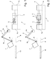
- the dashed line a illustrates the central longitudinal axis of the carcass construction machine 1.
- the components of the carcass construction machine 1 include a winding drum 2 and a core centering device 3 with left and right core centering segments for two cores.
- the outer diameter of the segments of the core centering device 3 can be changed by moving the segments in or out.
- the carcass construction machine 1 also has two core setting devices, not shown, which are arranged to be displaceable or movable along the longitudinal axis a and in the axial direction and which can be embodied in a manner known per se.
- winding drum 2 Conventional ones located to the side of the winding drum 2 are also not shown and bellows supports with inflatable bellows which can be moved in a manner known per se.
- the winding drum 2 is located on a stationary part of the carcass construction machine 1, the core centering device 3 on a part lb that can be moved away from the winding drum 2 in the direction of the axis a, so that the core centering device 3 is provided with a clearance from the winding drum 2 that is required to remove the completely assembled tire carcass can be driven away.
- the figures also show schematically a multi-axis, servomotor-controlled transfer device 4, which is in particular a robot.
- the transfer device 4 can, however, also be an XYZ adjustment unit.
- Two arms 4a, 4b of the transfer device 4 are shown by way of example, one arm 4a being articulated to a stationary base 5 and the two arms 4a, 4b also being articulated to one another.
- the articulated connections are each such that the arms 4a, 4b can be moved or rotated with respect to one another and the arm 4a can be moved or rotated with respect to the base 5 as desired.
- the arms 4a, 4b can be designed in several parts, for example to lengthen or shorten their arm length or to form further arm parts that are articulated to one another.
- a handling unit is provided, on which a core gripper 6 and a carcass gripper 7 are arranged such that either the core gripper 6 or the carcass gripper 7 can be actuated.
- the core gripper 6 is designed in such a way that it can pick up a pair of cores 9 and, as will be described below, deliver them to the core centering device.
- the cores 9 are positioned in a core store 8 ready for removal.
- the carcass gripper 7 is designed in such a way that it can grasp a completely assembled tire carcass from the outside in order to transfer it securely to a conveyor device 10, for example a conveyor belt.
- the position shown of the carcass construction machine 1 is its part 1b in its non-shifted starting position.
- a tire carcass 11 is wound from the individual components, as mentioned above, which in Fig. 2 is indicated.
- the transfer device 4 picks up a pair of cores 9 from the core storage 8 with its core gripper 6.
- the part 1b of the carcass building machine 1 is removed from the winding drum 2 moved away, with a free space between the core centering device 3 and the winding drum 2, as in Fig. 3 shown, arises, so that the transfer device 4, the received cores 9 on the core centering device 3, as is also shown in FIG Fig. 3 is indicated, can position.
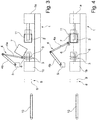
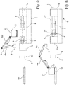
- the transfer device 4 then remains on the carcass construction machine 1 in a waiting position. As soon as the tire carcass 11 is completed, the transfer device 4 drives the carcass gripper 7 over the tire carcass 11 as it does Fig. 4 shows, grasps the tire carcass 11 from the outside and moves it along the axis a into the free space between the core centering device 3 and the winding drum 2. The tire carcass 11 picked up by the carcass gripper 7 is lifted by the transfer device 4 out of the area of the carcass construction machine 1, as shown in FIG Fig. 5 is shown. The part 1b of the carcass construction machine 1 is moved back, the right core setter (not shown) fetches the right core 9 and moves it back over the winding drum 2, Fig.
- FIG. 6 shows the core 9 positioned to the right of the winding drum 2. While the transfer device 4 transfers the tire carcass 11 to the conveyor device 10, the second core 9 is also taken over by the left core setter and positioned on the other side of the winding drum 2. The next tire carcass 11 is wound or built up in a manner known per se while the transfer device 4 again fetches two cores 9 from the core storage 8.
Landscapes
- Engineering & Computer Science (AREA)
- Mechanical Engineering (AREA)
- Tyre Moulding (AREA)
Claims (5)
- Dispositif destiné à être utilisé lors de la construction d'une carcasse de pneumatique (11) d'un pneumatique radial sur une machine de construction de carcasses (1) d'un système de construction de pneumatique, laquelle machine de construction de carcasses (1) comporte une partie fixe (1a) pourvue d'un tambour d'enroulement (2) et une partie (1b) mobile dans la direction axiale du tambour d'enroulement (2) et pourvue d'un dispositif de centrage de noyau (3) destiné à deux noyaux (9) du pneumatique radial,
caractérisé par
un dispositif de transfert multiaxes (4) commandé par servomoteur et pourvu d'un mécanisme de manutention qui comporte, en combinaison et de manière sélectivement actionnable, un moyen de préhension de noyaux (6) destiné à transférer les noyaux (9) d'un magasin de noyaux (8) au dispositif de centrage de noyaux (3) et un moyen de préhension de carcasses (7) destiné à saisir et transférer la carcasse de pneumatique montée (11) du tambour d'enroulement (2) à un mécanisme de transport (10). - Dispositif selon la revendication 1, caractérisé en ce que le dispositif de transfert (4) est un robot.
- Dispositif selon la revendication 1, caractérisé en ce que le dispositif de transfert (4) est une unité de réglage XYZ.
- Dispositif selon l'une des revendications 1 à 3, caractérisé en ce que le dispositif de transfert (4) est réalisé avec plusieurs bras, le mécanisme de manutention étant disposé au niveau de la zone d'extrémité d'un bras (4a).
- Procédé de construction d'une carcasse de pneumatique à l'aide d'un dispositif selon l'une des revendications 1 à 4, ledit procédé comprenant les étapes successives suivantes :a) monter une carcasse de pneumatique (11) sur le tambour d'enroulement (2) de la machine de construction de carcasses (1) tandis que le dispositif de transfert (4) reçoit à l'aide du moyen de préhension de noyaux (6) une paire de noyaux (9) provenant du magasin de noyaux (8),b) lors de l'achèvement de la carcasse de pneumatique (11), éloigner du tambour d'enroulement (2) la partie mobile (1b) de la machine de construction de carcasse (1), un espace libre étant généré entre le dispositif de centrage de noyaux (3) et le tambour d'enroulement (2) et le dispositif de transfert (4) positionnant les noyaux reçus (9) sur le dispositif de centrage de noyaux (3),c) laisser le dispositif de transfert (4) sur la machine de construction de carcasses (1) dans une position d'attente,d) après l'achèvement de la carcasse de pneumatique (11), déplacer le moyen de préhension de carcasses (7) du dispositif de transfert (4) sur la carcasse de pneumatique (11),e) saisir la carcasse de pneumatique (11) de l'extérieur à l'aide du moyen de préhension de carcasses (7),f) déplacer la carcasse de pneumatique reçue (11) à l'aide du moyen de préhension de carcasses (7) le long de l'axe (a) du tambour d'enroulement (2) jusque dans l'espace libre ménagé entre le dispositif de centrage de noyau (3) et le tambour d'enroulement (2),g) soulever la carcasse de pneumatique (11) reçue par le moyen de préhension de carcasse (7) hors de la zone de la machine de construction de carcasses (1) à l'aide du dispositif de transfert (4),h) ramener la partie (1b) de la machine de construction de carcasses (1) qui a été éloignée à l'étape b),i) positionner un noyau (9) à l'aide d'un premier moyen de placement de noyaux du côté du tambour d'enroulement (2) qui est opposé à la partie mobile (1b) de la machine de construction de carcasses (1),j) transférer la carcasse de pneumatique (11) vers un mécanisme de transport (10) à l'aide du dispositif de transfert (4) et positionner un deuxième noyau (9) du côté du tambour d'enroulement (2) qui est dirigé vers la partie mobile (1b) de la machine de construction de carcasses (1) à l'aide d'un deuxième moyen de placement de noyaux etk) répéter les étapes a) à j).
Applications Claiming Priority (1)
| Application Number | Priority Date | Filing Date | Title |
|---|---|---|---|
| DE102017213748.7A DE102017213748A1 (de) | 2017-08-08 | 2017-08-08 | Vorrichtung zum Einsatz während des Aufbaus einer Reifenkarkasse eines Radialreifens |
Publications (2)
| Publication Number | Publication Date |
|---|---|
| EP3441216A1 EP3441216A1 (fr) | 2019-02-13 |
| EP3441216B1 true EP3441216B1 (fr) | 2021-11-03 |
Family
ID=62116777
Family Applications (1)
| Application Number | Title | Priority Date | Filing Date |
|---|---|---|---|
| EP18170958.5A Active EP3441216B1 (fr) | 2017-08-08 | 2018-05-07 | Dispositif d'utilisation lors de la construction d'une carcasse de pneu d'un pneu radial et procédé de fabrication d'une carcasse pour pneu |
Country Status (2)
| Country | Link |
|---|---|
| EP (1) | EP3441216B1 (fr) |
| DE (1) | DE102017213748A1 (fr) |
Family Cites Families (7)
| Publication number | Priority date | Publication date | Assignee | Title |
|---|---|---|---|---|
| US4474399A (en) * | 1982-09-27 | 1984-10-02 | The Firestone Tire & Rubber Company | Tire gripper |
| GB8619617D0 (en) * | 1986-08-12 | 1986-09-24 | Apsley Metals Ltd | Tyre building machinery |
| JP3467120B2 (ja) * | 1995-06-06 | 2003-11-17 | 株式会社ブリヂストン | タイヤ成形機 |
| DE102004032511A1 (de) | 2004-07-06 | 2006-02-16 | Continental Aktiengesellschaft | Verfahren und Vorrichtung zum Positionieren von Wulstkernen |
| JP5406765B2 (ja) * | 2010-03-23 | 2014-02-05 | 株式会社ブリヂストン | バンド搬送装置 |
| JP5566504B1 (ja) * | 2013-06-05 | 2014-08-06 | 株式会社ブリヂストン | カーカスバンド成形装置及びカーカスバンド成形方法 |
| KR101595487B1 (ko) * | 2014-09-25 | 2016-02-18 | 금호타이어 주식회사 | 타이어 성형기용 그린 케이스 이송 장치 |
-
2017
- 2017-08-08 DE DE102017213748.7A patent/DE102017213748A1/de not_active Withdrawn
-
2018
- 2018-05-07 EP EP18170958.5A patent/EP3441216B1/fr active Active
Also Published As
| Publication number | Publication date |
|---|---|
| DE102017213748A1 (de) | 2019-02-14 |
| EP3441216A1 (fr) | 2019-02-13 |
Similar Documents
| Publication | Publication Date | Title |
|---|---|---|
| DE69511594T2 (de) | Konfektionierung und Vulkanisation von Reifen | |
| DE60211087T2 (de) | Verfahren zum Aufbringen von Reifenwulstkernen auf einer Reifenkarkasse | |
| DE102009025759A1 (de) | Verfahren und Vorrichtung zum Aufbauen eines PKW-Radialreifens | |
| EP1827808B1 (fr) | Procede et dispositif pour fabriquer un pneu radial | |
| EP1765581B1 (fr) | Procede et dispositif pour positionner des tringles de talon | |
| DE102018003301A1 (de) | Verfahren und Vorrichtung zur Herstellung von Reifen | |
| EP3034287B1 (fr) | Dispositif de production de paquets de noyaux pour pneumatiques de vehicule | |
| EP3441216B1 (fr) | Dispositif d'utilisation lors de la construction d'une carcasse de pneu d'un pneu radial et procédé de fabrication d'une carcasse pour pneu | |
| WO2015010678A1 (fr) | Procédé et dispositif permettant de transférer un ensemble de segments de piston | |
| DE112006003897T5 (de) | Bandabnehmverfahren bei einer Bandaufbautrommel sowie Bandaufbautrommel | |
| EP2789458B1 (fr) | Procédé et installation de fabrication d'une carcasse de pneu de véhicule | |
| DE102018205327A1 (de) | Vorrichtung zur Reifenrohlingherstellung | |
| DE102019203226A1 (de) | Verfahren zum Aufbauen eines Rohreifens | |
| EP4096909B1 (fr) | Procédé et dispositif de vulcanisation de pneumatiques | |
| EP3221135B1 (fr) | Dispositif et unité de transport pour la manipulation de pneus crus | |
| DE2821709C2 (de) | Vorrichtung zum Abbau und Wiederzusammenbau eines aus mehreren Segmenten bestehenden Laufflächenringes | |
| DE102020203374A1 (de) | Vorrichtung zur Herstellung einer Reifenkarkasse für einen Fahrzeugreifen | |
| DE102009025758A1 (de) | Verfahren zum Aufbauen eines Fahrzeugreifens für einen Personenkraftwagen mit einer Reifenaufbaumaschine | |
| DE2902022C2 (de) | Verfahren zum Aufbau von Luftreifen und Einrichtung zur Ausführung desselben | |
| DE102013103633A1 (de) | Verfahren und Anlage zur Herstellung einer Karkasse für einen Fahrzeugluftreifen | |
| WO2018228624A1 (fr) | Procédé et dispositif de fabrication de pneumatiques | |
| DE10319149B4 (de) | Verfahren zum Aufbau und Bombieren einer Reifenkarkasse sowie Anlage zur Durchführung eines solchen Verfahrens | |
| DE1579326C (de) | Reifenaufbaumaschine mit einer Auf bautrommel von unveränderlichem Durchmes | |
| DE102016214627A1 (de) | Verfahren und Vorrichtung zum Aufbauen eines Fahrzeugluftreifens | |
| DE102019119474A1 (de) | Verfahren und Vorrichtung zur Herstellung von Reifenrohlingen |
Legal Events
| Date | Code | Title | Description |
|---|---|---|---|
| PUAI | Public reference made under article 153(3) epc to a published international application that has entered the european phase |
Free format text: ORIGINAL CODE: 0009012 |
|
| STAA | Information on the status of an ep patent application or granted ep patent |
Free format text: STATUS: THE APPLICATION HAS BEEN PUBLISHED |
|
| AK | Designated contracting states |
Kind code of ref document: A1 Designated state(s): AL AT BE BG CH CY CZ DE DK EE ES FI FR GB GR HR HU IE IS IT LI LT LU LV MC MK MT NL NO PL PT RO RS SE SI SK SM TR |
|
| AX | Request for extension of the european patent |
Extension state: BA ME |
|
| STAA | Information on the status of an ep patent application or granted ep patent |
Free format text: STATUS: REQUEST FOR EXAMINATION WAS MADE |
|
| 17P | Request for examination filed |
Effective date: 20190813 |
|
| RBV | Designated contracting states (corrected) |
Designated state(s): AL AT BE BG CH CY CZ DE DK EE ES FI FR GB GR HR HU IE IS IT LI LT LU LV MC MK MT NL NO PL PT RO RS SE SI SK SM TR |
|
| RAP1 | Party data changed (applicant data changed or rights of an application transferred) |
Owner name: CONTINENTAL REIFEN DEUTSCHLAND GMBH |
|
| GRAP | Despatch of communication of intention to grant a patent |
Free format text: ORIGINAL CODE: EPIDOSNIGR1 |
|
| STAA | Information on the status of an ep patent application or granted ep patent |
Free format text: STATUS: GRANT OF PATENT IS INTENDED |
|
| INTG | Intention to grant announced |
Effective date: 20210714 |
|
| GRAS | Grant fee paid |
Free format text: ORIGINAL CODE: EPIDOSNIGR3 |
|
| GRAA | (expected) grant |
Free format text: ORIGINAL CODE: 0009210 |
|
| STAA | Information on the status of an ep patent application or granted ep patent |
Free format text: STATUS: THE PATENT HAS BEEN GRANTED |
|
| AK | Designated contracting states |
Kind code of ref document: B1 Designated state(s): AL AT BE BG CH CY CZ DE DK EE ES FI FR GB GR HR HU IE IS IT LI LT LU LV MC MK MT NL NO PL PT RO RS SE SI SK SM TR |
|
| REG | Reference to a national code |
Ref country code: GB Ref legal event code: FG4D Free format text: NOT ENGLISH |
|
| REG | Reference to a national code |
Ref country code: AT Ref legal event code: REF Ref document number: 1443611 Country of ref document: AT Kind code of ref document: T Effective date: 20211115 Ref country code: CH Ref legal event code: EP |
|
| REG | Reference to a national code |
Ref country code: DE Ref legal event code: R096 Ref document number: 502018007648 Country of ref document: DE |
|
| REG | Reference to a national code |
Ref country code: IE Ref legal event code: FG4D Free format text: LANGUAGE OF EP DOCUMENT: GERMAN |
|
| REG | Reference to a national code |
Ref country code: LT Ref legal event code: MG9D |
|
| REG | Reference to a national code |
Ref country code: NL Ref legal event code: MP Effective date: 20211103 |
|
| PG25 | Lapsed in a contracting state [announced via postgrant information from national office to epo] |
Ref country code: RS Free format text: LAPSE BECAUSE OF FAILURE TO SUBMIT A TRANSLATION OF THE DESCRIPTION OR TO PAY THE FEE WITHIN THE PRESCRIBED TIME-LIMIT Effective date: 20211103 Ref country code: LT Free format text: LAPSE BECAUSE OF FAILURE TO SUBMIT A TRANSLATION OF THE DESCRIPTION OR TO PAY THE FEE WITHIN THE PRESCRIBED TIME-LIMIT Effective date: 20211103 Ref country code: FI Free format text: LAPSE BECAUSE OF FAILURE TO SUBMIT A TRANSLATION OF THE DESCRIPTION OR TO PAY THE FEE WITHIN THE PRESCRIBED TIME-LIMIT Effective date: 20211103 Ref country code: BG Free format text: LAPSE BECAUSE OF FAILURE TO SUBMIT A TRANSLATION OF THE DESCRIPTION OR TO PAY THE FEE WITHIN THE PRESCRIBED TIME-LIMIT Effective date: 20220203 |
|
| PG25 | Lapsed in a contracting state [announced via postgrant information from national office to epo] |
Ref country code: IS Free format text: LAPSE BECAUSE OF FAILURE TO SUBMIT A TRANSLATION OF THE DESCRIPTION OR TO PAY THE FEE WITHIN THE PRESCRIBED TIME-LIMIT Effective date: 20220303 Ref country code: SE Free format text: LAPSE BECAUSE OF FAILURE TO SUBMIT A TRANSLATION OF THE DESCRIPTION OR TO PAY THE FEE WITHIN THE PRESCRIBED TIME-LIMIT Effective date: 20211103 Ref country code: PT Free format text: LAPSE BECAUSE OF FAILURE TO SUBMIT A TRANSLATION OF THE DESCRIPTION OR TO PAY THE FEE WITHIN THE PRESCRIBED TIME-LIMIT Effective date: 20220303 Ref country code: PL Free format text: LAPSE BECAUSE OF FAILURE TO SUBMIT A TRANSLATION OF THE DESCRIPTION OR TO PAY THE FEE WITHIN THE PRESCRIBED TIME-LIMIT Effective date: 20211103 Ref country code: NO Free format text: LAPSE BECAUSE OF FAILURE TO SUBMIT A TRANSLATION OF THE DESCRIPTION OR TO PAY THE FEE WITHIN THE PRESCRIBED TIME-LIMIT Effective date: 20220203 Ref country code: NL Free format text: LAPSE BECAUSE OF FAILURE TO SUBMIT A TRANSLATION OF THE DESCRIPTION OR TO PAY THE FEE WITHIN THE PRESCRIBED TIME-LIMIT Effective date: 20211103 Ref country code: LV Free format text: LAPSE BECAUSE OF FAILURE TO SUBMIT A TRANSLATION OF THE DESCRIPTION OR TO PAY THE FEE WITHIN THE PRESCRIBED TIME-LIMIT Effective date: 20211103 Ref country code: HR Free format text: LAPSE BECAUSE OF FAILURE TO SUBMIT A TRANSLATION OF THE DESCRIPTION OR TO PAY THE FEE WITHIN THE PRESCRIBED TIME-LIMIT Effective date: 20211103 Ref country code: GR Free format text: LAPSE BECAUSE OF FAILURE TO SUBMIT A TRANSLATION OF THE DESCRIPTION OR TO PAY THE FEE WITHIN THE PRESCRIBED TIME-LIMIT Effective date: 20220204 Ref country code: ES Free format text: LAPSE BECAUSE OF FAILURE TO SUBMIT A TRANSLATION OF THE DESCRIPTION OR TO PAY THE FEE WITHIN THE PRESCRIBED TIME-LIMIT Effective date: 20211103 |
|
| PG25 | Lapsed in a contracting state [announced via postgrant information from national office to epo] |
Ref country code: SM Free format text: LAPSE BECAUSE OF FAILURE TO SUBMIT A TRANSLATION OF THE DESCRIPTION OR TO PAY THE FEE WITHIN THE PRESCRIBED TIME-LIMIT Effective date: 20211103 Ref country code: SK Free format text: LAPSE BECAUSE OF FAILURE TO SUBMIT A TRANSLATION OF THE DESCRIPTION OR TO PAY THE FEE WITHIN THE PRESCRIBED TIME-LIMIT Effective date: 20211103 Ref country code: RO Free format text: LAPSE BECAUSE OF FAILURE TO SUBMIT A TRANSLATION OF THE DESCRIPTION OR TO PAY THE FEE WITHIN THE PRESCRIBED TIME-LIMIT Effective date: 20211103 Ref country code: EE Free format text: LAPSE BECAUSE OF FAILURE TO SUBMIT A TRANSLATION OF THE DESCRIPTION OR TO PAY THE FEE WITHIN THE PRESCRIBED TIME-LIMIT Effective date: 20211103 Ref country code: DK Free format text: LAPSE BECAUSE OF FAILURE TO SUBMIT A TRANSLATION OF THE DESCRIPTION OR TO PAY THE FEE WITHIN THE PRESCRIBED TIME-LIMIT Effective date: 20211103 Ref country code: CZ Free format text: LAPSE BECAUSE OF FAILURE TO SUBMIT A TRANSLATION OF THE DESCRIPTION OR TO PAY THE FEE WITHIN THE PRESCRIBED TIME-LIMIT Effective date: 20211103 |
|
| REG | Reference to a national code |
Ref country code: DE Ref legal event code: R097 Ref document number: 502018007648 Country of ref document: DE |
|
| PLBE | No opposition filed within time limit |
Free format text: ORIGINAL CODE: 0009261 |
|
| STAA | Information on the status of an ep patent application or granted ep patent |
Free format text: STATUS: NO OPPOSITION FILED WITHIN TIME LIMIT |
|
| 26N | No opposition filed |
Effective date: 20220804 |
|
| PG25 | Lapsed in a contracting state [announced via postgrant information from national office to epo] |
Ref country code: AL Free format text: LAPSE BECAUSE OF FAILURE TO SUBMIT A TRANSLATION OF THE DESCRIPTION OR TO PAY THE FEE WITHIN THE PRESCRIBED TIME-LIMIT Effective date: 20211103 |
|
| PG25 | Lapsed in a contracting state [announced via postgrant information from national office to epo] |
Ref country code: SI Free format text: LAPSE BECAUSE OF FAILURE TO SUBMIT A TRANSLATION OF THE DESCRIPTION OR TO PAY THE FEE WITHIN THE PRESCRIBED TIME-LIMIT Effective date: 20211103 |
|
| REG | Reference to a national code |
Ref country code: CH Ref legal event code: PL |
|
| REG | Reference to a national code |
Ref country code: BE Ref legal event code: MM Effective date: 20220531 |
|
| GBPC | Gb: european patent ceased through non-payment of renewal fee |
Effective date: 20220507 |
|
| PG25 | Lapsed in a contracting state [announced via postgrant information from national office to epo] |
Ref country code: MC Free format text: LAPSE BECAUSE OF FAILURE TO SUBMIT A TRANSLATION OF THE DESCRIPTION OR TO PAY THE FEE WITHIN THE PRESCRIBED TIME-LIMIT Effective date: 20211103 Ref country code: LU Free format text: LAPSE BECAUSE OF NON-PAYMENT OF DUE FEES Effective date: 20220507 Ref country code: LI Free format text: LAPSE BECAUSE OF NON-PAYMENT OF DUE FEES Effective date: 20220531 Ref country code: CH Free format text: LAPSE BECAUSE OF NON-PAYMENT OF DUE FEES Effective date: 20220531 |
|
| PG25 | Lapsed in a contracting state [announced via postgrant information from national office to epo] |
Ref country code: IE Free format text: LAPSE BECAUSE OF NON-PAYMENT OF DUE FEES Effective date: 20220507 |
|
| PG25 | Lapsed in a contracting state [announced via postgrant information from national office to epo] |
Ref country code: IT Free format text: LAPSE BECAUSE OF FAILURE TO SUBMIT A TRANSLATION OF THE DESCRIPTION OR TO PAY THE FEE WITHIN THE PRESCRIBED TIME-LIMIT Effective date: 20211103 Ref country code: GB Free format text: LAPSE BECAUSE OF NON-PAYMENT OF DUE FEES Effective date: 20220507 Ref country code: BE Free format text: LAPSE BECAUSE OF NON-PAYMENT OF DUE FEES Effective date: 20220531 |
|
| REG | Reference to a national code |
Ref country code: DE Ref legal event code: R081 Ref document number: 502018007648 Country of ref document: DE Owner name: CONTINENTAL REIFEN DEUTSCHLAND GMBH, DE Free format text: FORMER OWNER: CONTINENTAL REIFEN DEUTSCHLAND GMBH, 30165 HANNOVER, DE |
|
| PG25 | Lapsed in a contracting state [announced via postgrant information from national office to epo] |
Ref country code: HU Free format text: LAPSE BECAUSE OF FAILURE TO SUBMIT A TRANSLATION OF THE DESCRIPTION OR TO PAY THE FEE WITHIN THE PRESCRIBED TIME-LIMIT; INVALID AB INITIO Effective date: 20180507 |
|
| PG25 | Lapsed in a contracting state [announced via postgrant information from national office to epo] |
Ref country code: MK Free format text: LAPSE BECAUSE OF FAILURE TO SUBMIT A TRANSLATION OF THE DESCRIPTION OR TO PAY THE FEE WITHIN THE PRESCRIBED TIME-LIMIT Effective date: 20211103 Ref country code: CY Free format text: LAPSE BECAUSE OF FAILURE TO SUBMIT A TRANSLATION OF THE DESCRIPTION OR TO PAY THE FEE WITHIN THE PRESCRIBED TIME-LIMIT Effective date: 20211103 |
|
| REG | Reference to a national code |
Ref country code: AT Ref legal event code: MM01 Ref document number: 1443611 Country of ref document: AT Kind code of ref document: T Effective date: 20230507 |
|
| PG25 | Lapsed in a contracting state [announced via postgrant information from national office to epo] |
Ref country code: AT Free format text: LAPSE BECAUSE OF NON-PAYMENT OF DUE FEES Effective date: 20230507 |
|
| PG25 | Lapsed in a contracting state [announced via postgrant information from national office to epo] |
Ref country code: AT Free format text: LAPSE BECAUSE OF NON-PAYMENT OF DUE FEES Effective date: 20230507 |
|
| PG25 | Lapsed in a contracting state [announced via postgrant information from national office to epo] |
Ref country code: MT Free format text: LAPSE BECAUSE OF FAILURE TO SUBMIT A TRANSLATION OF THE DESCRIPTION OR TO PAY THE FEE WITHIN THE PRESCRIBED TIME-LIMIT Effective date: 20211103 |
|
| PGFP | Annual fee paid to national office [announced via postgrant information from national office to epo] |
Ref country code: DE Payment date: 20250531 Year of fee payment: 8 |
|
| PGFP | Annual fee paid to national office [announced via postgrant information from national office to epo] |
Ref country code: FR Payment date: 20250528 Year of fee payment: 8 |
|
| PG25 | Lapsed in a contracting state [announced via postgrant information from national office to epo] |
Ref country code: TR Free format text: LAPSE BECAUSE OF FAILURE TO SUBMIT A TRANSLATION OF THE DESCRIPTION OR TO PAY THE FEE WITHIN THE PRESCRIBED TIME-LIMIT Effective date: 20211103 |
|
| PGFP | Annual fee paid to national office [announced via postgrant information from national office to epo] |
Ref country code: AT Payment date: 20260410 Year of fee payment: 5 |