EP3441216B1 - Device for use during the construction of a tyre carcass of a radial tyre and method for manufacturing a carcass of a tyre - Google Patents
Device for use during the construction of a tyre carcass of a radial tyre and method for manufacturing a carcass of a tyre Download PDFInfo
- Publication number
- EP3441216B1 EP3441216B1 EP18170958.5A EP18170958A EP3441216B1 EP 3441216 B1 EP3441216 B1 EP 3441216B1 EP 18170958 A EP18170958 A EP 18170958A EP 3441216 B1 EP3441216 B1 EP 3441216B1
- Authority
- EP
- European Patent Office
- Prior art keywords
- carcass
- core
- tyre
- winding drum
- gripper
- Prior art date
- Legal status (The legal status is an assumption and is not a legal conclusion. Google has not performed a legal analysis and makes no representation as to the accuracy of the status listed.)
- Active
Links
Images
Classifications
-
- B—PERFORMING OPERATIONS; TRANSPORTING
- B29—WORKING OF PLASTICS; WORKING OF SUBSTANCES IN A PLASTIC STATE IN GENERAL
- B29D—PRODUCING PARTICULAR ARTICLES FROM PLASTICS OR FROM SUBSTANCES IN A PLASTIC STATE
- B29D30/00—Producing pneumatic or solid tyres or parts thereof
- B29D30/0016—Handling tyres or parts thereof, e.g. supplying, storing, conveying
-
- B—PERFORMING OPERATIONS; TRANSPORTING
- B29—WORKING OF PLASTICS; WORKING OF SUBSTANCES IN A PLASTIC STATE IN GENERAL
- B29D—PRODUCING PARTICULAR ARTICLES FROM PLASTICS OR FROM SUBSTANCES IN A PLASTIC STATE
- B29D30/00—Producing pneumatic or solid tyres or parts thereof
- B29D30/06—Pneumatic tyres or parts thereof (e.g. produced by casting, moulding, compression moulding, injection moulding, centrifugal casting)
- B29D30/08—Building tyres
- B29D30/20—Building tyres by the flat-tyre method, i.e. building on cylindrical drums
- B29D30/24—Drums
- B29D30/26—Accessories or details, e.g. membranes, transfer rings
- B29D30/2607—Devices for transferring annular tyre components during the building-up stage, e.g. from the first stage to the second stage building drum
-
- B—PERFORMING OPERATIONS; TRANSPORTING
- B29—WORKING OF PLASTICS; WORKING OF SUBSTANCES IN A PLASTIC STATE IN GENERAL
- B29D—PRODUCING PARTICULAR ARTICLES FROM PLASTICS OR FROM SUBSTANCES IN A PLASTIC STATE
- B29D30/00—Producing pneumatic or solid tyres or parts thereof
- B29D30/0016—Handling tyres or parts thereof, e.g. supplying, storing, conveying
- B29D2030/0044—Handling tyre beads, e.g., storing, transporting, transferring and supplying to the toroidal support or to the drum
Definitions
- the invention relates to a device for use during the building of a tire carcass of a radial tire on a carcass building machine of a tire building system, which carcass building machine has a stationary part with a winding drum and a part movable in the axial direction of the winding drum with a core centering device for two cores of the radial tire.
- the carcass construction machine has an expandable winding drum, two bellows supports with inflatable bellows, a core centering device for two cores and two core setting devices which can be moved in the axial direction of the winding drum.
- the movable part of the carcass construction machine is moved away from the winding drum. This creates a free space between the winding drum and the core centering device, so that an operator can position the cores on the core centering device and remove a fully assembled tire carcass from the winding drum by hand immediately after completion.
- the operator is thus tied to the system and, in order to avoid the system coming to a standstill, must be available at the carcass building machine at exactly two times, namely to position cores on the core centering device for the next tire carcass to be built and to remove the tire carcass that is currently was built.
- the operator has little time available for other activities during the construction of a tire carcass.
- An apparatus for building a pneumatic vehicle tire which has a drum for building a carcass and a further drum for building a belt-tread package.
- the device further comprises a linearly movable transfer device which can pick up cores, transport them and place them on the carcass building drum and which is furthermore designed to transport the carcass produced.
- the invention is thus based on the object of being able to carry out the core loading and carcass removal operations without an operator, so that these other activities can be carried out without causing idle times.
- the task set is achieved with a device with a multi-axis, servomotor-controlled transfer device with a handling unit which, in combination and optionally actuatable, has a core gripper for transferring the cores from a core store to the core centering device and a carcass gripper for gripping and transferring the built-up tire carcass from the Having winding drum to a conveyor.
- the transfer device makes it possible to combine the operations of core loading and carcass removal with one another.
- the carcass gripper is already in the area of the carcass construction machine, by the winding drum, when the cores are positioned on the core centering device.
- the carcass gripper therefore only has a short way to the built-up tire carcass. This reduces the cycle time and, above all, the complexity of the entire machine.
- the transfer device is a robot.
- a robot can be moved in a particularly variable manner and therefore carry out the transfer movements in a particularly precise and rapid manner.
- the transfer device is an XYZ adjustment unit, which also has the advantage of variable mobility.
- the handling unit with the core gripper and the carcass gripper is preferably arranged at the end of an arm.
- Pneumatic vehicle tires in particular radial tires for passenger cars, are usually built as green tires in a two-stage process or by means of a tire-building machine having two stages.
- a tire carcass is built on a carcass construction machine 1, for example in a folding drum process, which has as main components an inner layer, a single or multi-layer carcass insert, bead cores with core profiles, bead reinforcements and sidewall profiles.
- the tire components belonging to a belt structure and the tire components belonging to a tread are built up on the tire carcass.
- tire components mentioned - inner layer, carcass insert, cores with core profiles, bead reinforcements, sidewall profiles, belt bandages and treads - are well known to a tire expert.
- cores the bead cores joined to the core profiles, as is customary in tire construction, are referred to as "cores”.
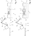
- the dashed line a illustrates the central longitudinal axis of the carcass construction machine 1.
- the components of the carcass construction machine 1 include a winding drum 2 and a core centering device 3 with left and right core centering segments for two cores.
- the outer diameter of the segments of the core centering device 3 can be changed by moving the segments in or out.
- the carcass construction machine 1 also has two core setting devices, not shown, which are arranged to be displaceable or movable along the longitudinal axis a and in the axial direction and which can be embodied in a manner known per se.
- winding drum 2 Conventional ones located to the side of the winding drum 2 are also not shown and bellows supports with inflatable bellows which can be moved in a manner known per se.
- the winding drum 2 is located on a stationary part of the carcass construction machine 1, the core centering device 3 on a part lb that can be moved away from the winding drum 2 in the direction of the axis a, so that the core centering device 3 is provided with a clearance from the winding drum 2 that is required to remove the completely assembled tire carcass can be driven away.
- the figures also show schematically a multi-axis, servomotor-controlled transfer device 4, which is in particular a robot.
- the transfer device 4 can, however, also be an XYZ adjustment unit.
- Two arms 4a, 4b of the transfer device 4 are shown by way of example, one arm 4a being articulated to a stationary base 5 and the two arms 4a, 4b also being articulated to one another.
- the articulated connections are each such that the arms 4a, 4b can be moved or rotated with respect to one another and the arm 4a can be moved or rotated with respect to the base 5 as desired.
- the arms 4a, 4b can be designed in several parts, for example to lengthen or shorten their arm length or to form further arm parts that are articulated to one another.
- a handling unit is provided, on which a core gripper 6 and a carcass gripper 7 are arranged such that either the core gripper 6 or the carcass gripper 7 can be actuated.
- the core gripper 6 is designed in such a way that it can pick up a pair of cores 9 and, as will be described below, deliver them to the core centering device.
- the cores 9 are positioned in a core store 8 ready for removal.
- the carcass gripper 7 is designed in such a way that it can grasp a completely assembled tire carcass from the outside in order to transfer it securely to a conveyor device 10, for example a conveyor belt.
- the position shown of the carcass construction machine 1 is its part 1b in its non-shifted starting position.
- a tire carcass 11 is wound from the individual components, as mentioned above, which in Fig. 2 is indicated.
- the transfer device 4 picks up a pair of cores 9 from the core storage 8 with its core gripper 6.
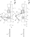
- the part 1b of the carcass building machine 1 is removed from the winding drum 2 moved away, with a free space between the core centering device 3 and the winding drum 2, as in Fig. 3 shown, arises, so that the transfer device 4, the received cores 9 on the core centering device 3, as is also shown in FIG Fig. 3 is indicated, can position.
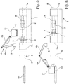
- the transfer device 4 then remains on the carcass construction machine 1 in a waiting position. As soon as the tire carcass 11 is completed, the transfer device 4 drives the carcass gripper 7 over the tire carcass 11 as it does Fig. 4 shows, grasps the tire carcass 11 from the outside and moves it along the axis a into the free space between the core centering device 3 and the winding drum 2. The tire carcass 11 picked up by the carcass gripper 7 is lifted by the transfer device 4 out of the area of the carcass construction machine 1, as shown in FIG Fig. 5 is shown. The part 1b of the carcass construction machine 1 is moved back, the right core setter (not shown) fetches the right core 9 and moves it back over the winding drum 2, Fig.
- FIG. 6 shows the core 9 positioned to the right of the winding drum 2. While the transfer device 4 transfers the tire carcass 11 to the conveyor device 10, the second core 9 is also taken over by the left core setter and positioned on the other side of the winding drum 2. The next tire carcass 11 is wound or built up in a manner known per se while the transfer device 4 again fetches two cores 9 from the core storage 8.
Landscapes
- Engineering & Computer Science (AREA)
- Mechanical Engineering (AREA)
- Tyre Moulding (AREA)
Description
Die Erfindung betrifft eine Vorrichtung zum Einsatz während des Aufbaus einer Reifenkarkasse eines Radialreifens auf einer Karkassbaumaschine einer Reifenaufbauanlage, welche Karkassbaumaschine einen stationären Teil mit einer Wickeltrommel und einen in Achsrichtung der Wickeltrommel verfahrbaren Teil mit einer Kernzentriervorrichtung für zwei Kerne des Radialreifens aufweist.The invention relates to a device for use during the building of a tire carcass of a radial tire on a carcass building machine of a tire building system, which carcass building machine has a stationary part with a winding drum and a part movable in the axial direction of the winding drum with a core centering device for two cores of the radial tire.
Eine derartige Vorrichtung ist aus der
Aus der
Der Erfindung liegt somit die Aufgabe zu Grunde, den Vorgang der Kernbeladung und der Karkassenentnahme ohne Bedienperson durchführen zu können, so dass diese anderen Tätigkeiten ohne Leerzeiten zu verursachen nachgehen kann. Darüber hinaus soll durch ein Automatisieren der Vorgänge Kernbeladung und Karkassenentnahme die Produktivität der Anlage gesteigert werden können.The invention is thus based on the object of being able to carry out the core loading and carcass removal operations without an operator, so that these other activities can be carried out without causing idle times. In addition, it should be possible to increase the productivity of the system by automating the core loading and carcass removal processes.
Gelöst wird die gestellte Aufgabe mit einer Vorrichtung mit einer mehrachsigen, servomotorisch gesteuerten Transfervorrichtung mit einer Handhabungseinheit, welche in Kombination und wahlweise betätigbar einen Kerngreifer zum Transfer der Kerne aus einem Kernspeicher auf die Kernzentriervorrichtung und einen Karkassengreifer zum Erfassen und zum Transfer der aufgebauten Reifenkarkasse von der Wickeltrommel zu einer Fördereinrichtung aufweist.The task set is achieved with a device with a multi-axis, servomotor-controlled transfer device with a handling unit which, in combination and optionally actuatable, has a core gripper for transferring the cores from a core store to the core centering device and a carcass gripper for gripping and transferring the built-up tire carcass from the Having winding drum to a conveyor.
Die erfindungsgemäße Transfervorrichtung gestattet es, die Vorgänge des Kernbeladens und der Karkassenentnahme miteinander zu kombinieren. Der Karkassengreifer befindet sich bereits im Bereich der Karkassbaumaschine, bei der Wickeltrommel, wenn die Kerne auf der Kernzentriervorrichtung positioniert werden. Der Karkassengreifer hat daher nur noch einen kurzen Weg zur aufgebauten Reifenkarkasse. Dadurch werden die Zykluszeit und vor allem auch die Komplexität der gesamten Maschine reduziert.The transfer device according to the invention makes it possible to combine the operations of core loading and carcass removal with one another. The carcass gripper is already in the area of the carcass construction machine, by the winding drum, when the cores are positioned on the core centering device. The carcass gripper therefore only has a short way to the built-up tire carcass. This reduces the cycle time and, above all, the complexity of the entire machine.
Bei einer bevorzugten Ausführungsform ist die Transfervorrichtung ein Roboter. Ein Roboter kann auf besonders variable Weise bewegt werden und daher die Transferbewegungen auf eine besonders exakte und schnelle Weise durchführen. Bei einer alternativen Ausführung ist die Transfereinrichtung eine XYZ-Verstelleinheit, welche ebenfalls den Vorteil einer variablen Beweglichkeit aufweist.In a preferred embodiment, the transfer device is a robot. A robot can be moved in a particularly variable manner and therefore carry out the transfer movements in a particularly precise and rapid manner. In an alternative embodiment, the transfer device is an XYZ adjustment unit, which also has the advantage of variable mobility.
Besonders bevorzugt ist eine Ausführung der Transfervorrichtung mit mehreren, miteinander gelenkig verbundenen Armen. Die Handhabungseinheit mit dem Kerngreifer und dem Karkassengreifer ist bevorzugt am Ende eines Armes angeordnet.Particularly preferred is an embodiment of the transfer device with several arms that are articulated with one another. The handling unit with the core gripper and the carcass gripper is preferably arranged at the end of an arm.
Weitere Merkmale, Vorteile und Einzelheiten der Erfindung werden nun anhand der schematischen Zeichnung, die ein Ausführungsbeispiel darstellt, näher beschrieben. Dabei zeigen
- Fig. 1
- eine Übersicht der Vorrichtung gemäß der Erfindung und
- Fig. 2 bis Fig. 6
- die grundsätzliche Funktionsweise der erfindungsgemäßen Vorrichtung.
- Fig. 1
- an overview of the device according to the invention and
- FIGS. 2 to 6
- the basic functionality of the device according to the invention.
Fahrzeugluftreifen, insbesondere Radialreifen für Personenkraftwagen, werden üblicherweise in einem zweistufigen Verfahren bzw. mittels einer zwei Stufen aufweisenden Reifenaufbaumaschine als Rohreifen aufgebaut. In der ersten Stufe wird auf einer Karkassbaumaschine 1 beispielweise in einem Klapptrommel-Verfahren eine Reifenkarkasse aufgebaut, welche als Hauptbestandteile eine Innenschicht, eine ein- oder mehrlagige Karkasseinlage, Wulstkerne mit Kernprofilen, Wulstverstärker und Seitenwandprofile aufweist. Auf der zweiten Stufe der Reifenaufbaumaschine, die nicht Gegenstand der Erfindung ist, werden die zu einem Gürtelverband und die zu einem Laufstreifen gehörenden Reifenbauteile auf der Reifenkarkasse aufgebaut. Sämtliche erwähnten Reifenbauteile - Innenschicht, Karkasseinlage, Kerne mit Kernprofilen, Wulstverstärker, Seitenwandprofile, Gürtelverband und Laufstreifen - sind einem Reifenfachmann hinlänglich bekannt. In der nachfolgenden Beschreibung werden die mit den Kernprofilen zusammengefügten Wulstkerne, wie es im Reifenaufbau üblich ist, als "Kerne" bezeichnet.Pneumatic vehicle tires, in particular radial tires for passenger cars, are usually built as green tires in a two-stage process or by means of a tire-building machine having two stages. In the first stage, a tire carcass is built on a carcass construction machine 1, for example in a folding drum process, which has as main components an inner layer, a single or multi-layer carcass insert, bead cores with core profiles, bead reinforcements and sidewall profiles. In the second stage of the tire building machine, which is not the subject of the invention, the tire components belonging to a belt structure and the tire components belonging to a tread are built up on the tire carcass. All of the tire components mentioned - inner layer, carcass insert, cores with core profiles, bead reinforcements, sidewall profiles, belt bandages and treads - are well known to a tire expert. In the following description, the bead cores joined to the core profiles, as is customary in tire construction, are referred to as "cores".
In den
Die Figuren zeigen ferner schematisch eine mehrachsige, servomotorisch gesteuerte Transfervorrichtung 4, welche insbesondere ein Roboter ist. Die Transfervorrichtung 4 kann jedoch auch eine XYZ-Verstelleinheit sein. Von der Transfervorrichtung 4 sind beispielhaft zwei Arme 4a, 4b dargestellt, wobei der eine Arm 4a gelenkig mit einer stationären Basis 5 verbunden ist und die beiden Arme 4a, 4b miteinander ebenfalls gelenkig verbunden sind. Die gelenkigen Verbindungen sind jeweils derart, dass die Arme 4a, 4b gegeneinander und der Arm 4a gegenüber der Basis 5 beliebig bewegt bzw. gedreht werden können. Die Arme 4a, 4b können mehrteilig ausgeführt sein, beispielsweise zur Verlängerung bzw. Verkürzung ihrer Armlänge oder um weitere, gelenkig miteinander verbundene Armteile zu bilden. Am freien Endbereich des Armes 4b ist eine nicht gezeigte Handhabungseinheit vorgesehen, an welcher ein Kerngreifer 6 und ein Karkassengreifer 7 derart angeordnet sind, dass wahlweise der Kerngreifer 6 oder der Karkassengreifer 7 betätigt werden kann. Der Kerngreifer 6 ist derart gestaltet, dass er ein Paar von Kernen 9 aufnehmen und, wie noch beschrieben wird, an die Kernzentriervorrichtung abgeben kann. Die Kern 9 sind in einem Kernspeicher 8 entnahmefertig positioniert. Der Karkassengreifer 7 ist derart gestaltet, dass er eine fertig aufgebaute Reifenkarkasse von außen erfassen kann, um diese sicher zu einer eine Fördereinrichtung 10, beispielsweise einem Förderband, zu transferieren.The figures also show schematically a multi-axis, servomotor-controlled
In der in
- 11
- KarkassbaumaschineCarcass making machine
- 1a, 1b1a, 1b
- Teilpart
- 22
- WickeltrommelWinding drum
- 33
- KernzentriervorrichtungCore centering device
- 44th
- TransfervorrichtungTransfer device
- 4a, 4b4a, 4b
- Armpoor
- 55
- BasisBase
- 66th
- KerngreiferCore grab
- 77th
- KarkassengreiferCarcass grab
- 88th
- KernspeicherCore memory
- 99
- Kerncore
- 1010
- FördereinrichtungConveyor
- 1111
- ReifenkarkasseTire carcass
- aa
- zentrale Längsachsecentral longitudinal axis
Claims (5)
- Apparatus for use during the building of a tyre carcass (11) of a radial tyre on a carcass building machine (1) of a tyre building plant, which carcass building machine (1) has a stationary part (1a), with a winding drum (2), and a part (1b) which can be moved in the axial direction of the winding drum (2) and has a core centring apparatus (3) for two cores (9) of the radial tyre, characterized by a multiaxial transfer apparatus (4) which is controlled by servomotor and has a handling unit which has, in combination and selectively actuably, a core gripper (6) for the transfer of the cores (9) from a core store (8) to the core centring apparatus (3), and a carcass gripper (7) for the gripping and for the transfer of the built tyre carcass (11) from the winding drum (2) to a conveying device (10).
- Apparatus according to Claim 1, characterized in that the transfer apparatus (4) is a robot.
- Apparatus according to Claim 1, characterized in that the transfer apparatus (4) is an XYZ adjusting unit.
- Apparatus according to one of Claims 1 to 3, characterized in that the transfer apparatus (4) is configured with multiple arms, the handling unit being arranged on the end region of an arm (4a).
- Method for building a tyre carcass with an apparatus according to one of Claims 1 to 4, with the following steps which take place consecutively:a) building of a tyre carcass (11) on the winding drum (2) of the carcass building machine (1) while the transfer apparatus (4) receives a pair of cores (9) from the core store (8) by way of the core gripper (6),b) moving of the movable part (1b) of the carcass building machine (1) away from the winding drum (2) during the completion of the tyre carcass (11), a clearance being produced between the core centring apparatus (3) and the winding drum (2), and the transfer apparatus (4) positioning the received cores (9) on the core centring apparatus (3),c) pausing of the transfer apparatus (4) on the carcass building machine (1) in a waiting position,d) moving of the carcass gripper (7) of the transfer apparatus (4) over the tyre carcass (11) after completion of the tyre carcass (11),e) gripping of the tyre carcass (11) from the outside by means of the carcass gripper (7),f) moving of the received tyre carcass (11) by means of the carcass gripper (7) along the axis (a) of the winding drum (2) into the clearance between the core centring apparatus (3) and the winding drum (2),g) lifting of the tyre carcass (11) which is received by the carcass gripper (7) out of the region of the carcass building machine (1) by means of the transfer apparatus (4),h) moving back of that part (1b) of the carcass building machine (1) which was moved away in step b) ,i) positioning of a core (9) on that side of the winding drum (2) which faces away from the movable part (1b) of the carcass building machine (1) by means of a first core setting means,j) transferring of the tyre carcass (11) to a conveying device (10) by means of the transfer apparatus (4), and positioning of a second core (9) on that side of the winding drum (2) which faces the movable part (1b) of the carcass building machine (1) by means of a second core setting means, andk) repeating of steps a) to j).
Applications Claiming Priority (1)
| Application Number | Priority Date | Filing Date | Title |
|---|---|---|---|
| DE102017213748.7A DE102017213748A1 (en) | 2017-08-08 | 2017-08-08 | Apparatus for use during the construction of a tire carcass of a radial tire |
Publications (2)
| Publication Number | Publication Date |
|---|---|
| EP3441216A1 EP3441216A1 (en) | 2019-02-13 |
| EP3441216B1 true EP3441216B1 (en) | 2021-11-03 |
Family
ID=62116777
Family Applications (1)
| Application Number | Title | Priority Date | Filing Date |
|---|---|---|---|
| EP18170958.5A Active EP3441216B1 (en) | 2017-08-08 | 2018-05-07 | Device for use during the construction of a tyre carcass of a radial tyre and method for manufacturing a carcass of a tyre |
Country Status (2)
| Country | Link |
|---|---|
| EP (1) | EP3441216B1 (en) |
| DE (1) | DE102017213748A1 (en) |
Family Cites Families (7)
| Publication number | Priority date | Publication date | Assignee | Title |
|---|---|---|---|---|
| US4474399A (en) * | 1982-09-27 | 1984-10-02 | The Firestone Tire & Rubber Company | Tire gripper |
| GB8619617D0 (en) * | 1986-08-12 | 1986-09-24 | Apsley Metals Ltd | Tyre building machinery |
| JP3467120B2 (en) * | 1995-06-06 | 2003-11-17 | 株式会社ブリヂストン | Tire building machine |
| DE102004032511A1 (en) | 2004-07-06 | 2006-02-16 | Continental Aktiengesellschaft | Method and device for positioning bead cores |
| JP5406765B2 (en) * | 2010-03-23 | 2014-02-05 | 株式会社ブリヂストン | Band conveyor |
| JP5566504B1 (en) * | 2013-06-05 | 2014-08-06 | 株式会社ブリヂストン | Carcass band molding apparatus and carcass band molding method |
| KR101595487B1 (en) * | 2014-09-25 | 2016-02-18 | 금호타이어 주식회사 | Device of transferring green case for tire builder |
-
2017
- 2017-08-08 DE DE102017213748.7A patent/DE102017213748A1/en not_active Withdrawn
-
2018
- 2018-05-07 EP EP18170958.5A patent/EP3441216B1/en active Active
Also Published As
| Publication number | Publication date |
|---|---|
| DE102017213748A1 (en) | 2019-02-14 |
| EP3441216A1 (en) | 2019-02-13 |
Similar Documents
| Publication | Publication Date | Title |
|---|---|---|
| DE69511594T2 (en) | Assembly and vulcanization of tires | |
| DE60211087T2 (en) | Method of applying tire bead cores to a tire carcass | |
| DE102009025759A1 (en) | Method for assembling radial tire for passenger car at tire building machine, involves laying tire carcass on building drum and expanding bellow carrier from inside at bead core | |
| EP1827808B1 (en) | Method and device for constructing a radial tyre | |
| EP2358519B1 (en) | Device for constructing a carcass for a vehicle tire | |
| EP1765581B1 (en) | Method and device for positioning bead wires | |
| DE102018003301A1 (en) | Method and device for producing tires | |
| DE1118137B (en) | Device for producing closed wire loops | |
| WO2015010678A1 (en) | Method and device for transferring a piston ring pack | |
| DE112006003897T5 (en) | Tape removal method in a band building drum and band building drum | |
| EP2789458B1 (en) | Method and a system for producing a carcase for a pneumatic tyre | |
| EP3441216A1 (en) | Device for use during the construction of a tyre carcass of a radial tyre | |
| DE102018205327A1 (en) | Apparatus for green tire production | |
| DE102019203226A1 (en) | Method of building a green tire | |
| EP4096909B1 (en) | Method and device for vulcanizing tires | |
| EP3221135B1 (en) | Device and transport device for handling tyre blanks | |
| DE2821709C2 (en) | Device for dismantling and reassembling a tread ring consisting of several segments | |
| DE102020203374A1 (en) | Device for producing a tire carcass for a vehicle tire | |
| DE102009025758A1 (en) | Method for assembling tire of passenger car, involves accomplishing tire carcass on winding- and shaping tool, removing completed tire blank from another winding- and shaping tool and subsequently processing tire blank | |
| DE2902022C2 (en) | Method of building pneumatic tires and apparatus for carrying out the same | |
| DE102013103633A1 (en) | Method and system for producing a carcass for a pneumatic vehicle tire | |
| EP3999327B1 (en) | Method and device for producing green tyres | |
| DE10319149B4 (en) | Method for building and crowning a tire carcass and installation for carrying out such a method | |
| DE1579326C (en) | Tire building machine with a building drum of unchangeable diameter | |
| DE102016214627A1 (en) | Method and device for building a pneumatic vehicle tire |
Legal Events
| Date | Code | Title | Description |
|---|---|---|---|
| PUAI | Public reference made under article 153(3) epc to a published international application that has entered the european phase |
Free format text: ORIGINAL CODE: 0009012 |
|
| STAA | Information on the status of an ep patent application or granted ep patent |
Free format text: STATUS: THE APPLICATION HAS BEEN PUBLISHED |
|
| AK | Designated contracting states |
Kind code of ref document: A1 Designated state(s): AL AT BE BG CH CY CZ DE DK EE ES FI FR GB GR HR HU IE IS IT LI LT LU LV MC MK MT NL NO PL PT RO RS SE SI SK SM TR |
|
| AX | Request for extension of the european patent |
Extension state: BA ME |
|
| STAA | Information on the status of an ep patent application or granted ep patent |
Free format text: STATUS: REQUEST FOR EXAMINATION WAS MADE |
|
| 17P | Request for examination filed |
Effective date: 20190813 |
|
| RBV | Designated contracting states (corrected) |
Designated state(s): AL AT BE BG CH CY CZ DE DK EE ES FI FR GB GR HR HU IE IS IT LI LT LU LV MC MK MT NL NO PL PT RO RS SE SI SK SM TR |
|
| RAP1 | Party data changed (applicant data changed or rights of an application transferred) |
Owner name: CONTINENTAL REIFEN DEUTSCHLAND GMBH |
|
| GRAP | Despatch of communication of intention to grant a patent |
Free format text: ORIGINAL CODE: EPIDOSNIGR1 |
|
| STAA | Information on the status of an ep patent application or granted ep patent |
Free format text: STATUS: GRANT OF PATENT IS INTENDED |
|
| INTG | Intention to grant announced |
Effective date: 20210714 |
|
| GRAS | Grant fee paid |
Free format text: ORIGINAL CODE: EPIDOSNIGR3 |
|
| GRAA | (expected) grant |
Free format text: ORIGINAL CODE: 0009210 |
|
| STAA | Information on the status of an ep patent application or granted ep patent |
Free format text: STATUS: THE PATENT HAS BEEN GRANTED |
|
| AK | Designated contracting states |
Kind code of ref document: B1 Designated state(s): AL AT BE BG CH CY CZ DE DK EE ES FI FR GB GR HR HU IE IS IT LI LT LU LV MC MK MT NL NO PL PT RO RS SE SI SK SM TR |
|
| REG | Reference to a national code |
Ref country code: GB Ref legal event code: FG4D Free format text: NOT ENGLISH |
|
| REG | Reference to a national code |
Ref country code: AT Ref legal event code: REF Ref document number: 1443611 Country of ref document: AT Kind code of ref document: T Effective date: 20211115 Ref country code: CH Ref legal event code: EP |
|
| REG | Reference to a national code |
Ref country code: DE Ref legal event code: R096 Ref document number: 502018007648 Country of ref document: DE |
|
| REG | Reference to a national code |
Ref country code: IE Ref legal event code: FG4D Free format text: LANGUAGE OF EP DOCUMENT: GERMAN |
|
| REG | Reference to a national code |
Ref country code: LT Ref legal event code: MG9D |
|
| REG | Reference to a national code |
Ref country code: NL Ref legal event code: MP Effective date: 20211103 |
|
| PG25 | Lapsed in a contracting state [announced via postgrant information from national office to epo] |
Ref country code: RS Free format text: LAPSE BECAUSE OF FAILURE TO SUBMIT A TRANSLATION OF THE DESCRIPTION OR TO PAY THE FEE WITHIN THE PRESCRIBED TIME-LIMIT Effective date: 20211103 Ref country code: LT Free format text: LAPSE BECAUSE OF FAILURE TO SUBMIT A TRANSLATION OF THE DESCRIPTION OR TO PAY THE FEE WITHIN THE PRESCRIBED TIME-LIMIT Effective date: 20211103 Ref country code: FI Free format text: LAPSE BECAUSE OF FAILURE TO SUBMIT A TRANSLATION OF THE DESCRIPTION OR TO PAY THE FEE WITHIN THE PRESCRIBED TIME-LIMIT Effective date: 20211103 Ref country code: BG Free format text: LAPSE BECAUSE OF FAILURE TO SUBMIT A TRANSLATION OF THE DESCRIPTION OR TO PAY THE FEE WITHIN THE PRESCRIBED TIME-LIMIT Effective date: 20220203 |
|
| PG25 | Lapsed in a contracting state [announced via postgrant information from national office to epo] |
Ref country code: IS Free format text: LAPSE BECAUSE OF FAILURE TO SUBMIT A TRANSLATION OF THE DESCRIPTION OR TO PAY THE FEE WITHIN THE PRESCRIBED TIME-LIMIT Effective date: 20220303 Ref country code: SE Free format text: LAPSE BECAUSE OF FAILURE TO SUBMIT A TRANSLATION OF THE DESCRIPTION OR TO PAY THE FEE WITHIN THE PRESCRIBED TIME-LIMIT Effective date: 20211103 Ref country code: PT Free format text: LAPSE BECAUSE OF FAILURE TO SUBMIT A TRANSLATION OF THE DESCRIPTION OR TO PAY THE FEE WITHIN THE PRESCRIBED TIME-LIMIT Effective date: 20220303 Ref country code: PL Free format text: LAPSE BECAUSE OF FAILURE TO SUBMIT A TRANSLATION OF THE DESCRIPTION OR TO PAY THE FEE WITHIN THE PRESCRIBED TIME-LIMIT Effective date: 20211103 Ref country code: NO Free format text: LAPSE BECAUSE OF FAILURE TO SUBMIT A TRANSLATION OF THE DESCRIPTION OR TO PAY THE FEE WITHIN THE PRESCRIBED TIME-LIMIT Effective date: 20220203 Ref country code: NL Free format text: LAPSE BECAUSE OF FAILURE TO SUBMIT A TRANSLATION OF THE DESCRIPTION OR TO PAY THE FEE WITHIN THE PRESCRIBED TIME-LIMIT Effective date: 20211103 Ref country code: LV Free format text: LAPSE BECAUSE OF FAILURE TO SUBMIT A TRANSLATION OF THE DESCRIPTION OR TO PAY THE FEE WITHIN THE PRESCRIBED TIME-LIMIT Effective date: 20211103 Ref country code: HR Free format text: LAPSE BECAUSE OF FAILURE TO SUBMIT A TRANSLATION OF THE DESCRIPTION OR TO PAY THE FEE WITHIN THE PRESCRIBED TIME-LIMIT Effective date: 20211103 Ref country code: GR Free format text: LAPSE BECAUSE OF FAILURE TO SUBMIT A TRANSLATION OF THE DESCRIPTION OR TO PAY THE FEE WITHIN THE PRESCRIBED TIME-LIMIT Effective date: 20220204 Ref country code: ES Free format text: LAPSE BECAUSE OF FAILURE TO SUBMIT A TRANSLATION OF THE DESCRIPTION OR TO PAY THE FEE WITHIN THE PRESCRIBED TIME-LIMIT Effective date: 20211103 |
|
| PG25 | Lapsed in a contracting state [announced via postgrant information from national office to epo] |
Ref country code: SM Free format text: LAPSE BECAUSE OF FAILURE TO SUBMIT A TRANSLATION OF THE DESCRIPTION OR TO PAY THE FEE WITHIN THE PRESCRIBED TIME-LIMIT Effective date: 20211103 Ref country code: SK Free format text: LAPSE BECAUSE OF FAILURE TO SUBMIT A TRANSLATION OF THE DESCRIPTION OR TO PAY THE FEE WITHIN THE PRESCRIBED TIME-LIMIT Effective date: 20211103 Ref country code: RO Free format text: LAPSE BECAUSE OF FAILURE TO SUBMIT A TRANSLATION OF THE DESCRIPTION OR TO PAY THE FEE WITHIN THE PRESCRIBED TIME-LIMIT Effective date: 20211103 Ref country code: EE Free format text: LAPSE BECAUSE OF FAILURE TO SUBMIT A TRANSLATION OF THE DESCRIPTION OR TO PAY THE FEE WITHIN THE PRESCRIBED TIME-LIMIT Effective date: 20211103 Ref country code: DK Free format text: LAPSE BECAUSE OF FAILURE TO SUBMIT A TRANSLATION OF THE DESCRIPTION OR TO PAY THE FEE WITHIN THE PRESCRIBED TIME-LIMIT Effective date: 20211103 Ref country code: CZ Free format text: LAPSE BECAUSE OF FAILURE TO SUBMIT A TRANSLATION OF THE DESCRIPTION OR TO PAY THE FEE WITHIN THE PRESCRIBED TIME-LIMIT Effective date: 20211103 |
|
| REG | Reference to a national code |
Ref country code: DE Ref legal event code: R097 Ref document number: 502018007648 Country of ref document: DE |
|
| PLBE | No opposition filed within time limit |
Free format text: ORIGINAL CODE: 0009261 |
|
| STAA | Information on the status of an ep patent application or granted ep patent |
Free format text: STATUS: NO OPPOSITION FILED WITHIN TIME LIMIT |
|
| 26N | No opposition filed |
Effective date: 20220804 |
|
| PG25 | Lapsed in a contracting state [announced via postgrant information from national office to epo] |
Ref country code: AL Free format text: LAPSE BECAUSE OF FAILURE TO SUBMIT A TRANSLATION OF THE DESCRIPTION OR TO PAY THE FEE WITHIN THE PRESCRIBED TIME-LIMIT Effective date: 20211103 |
|
| PG25 | Lapsed in a contracting state [announced via postgrant information from national office to epo] |
Ref country code: SI Free format text: LAPSE BECAUSE OF FAILURE TO SUBMIT A TRANSLATION OF THE DESCRIPTION OR TO PAY THE FEE WITHIN THE PRESCRIBED TIME-LIMIT Effective date: 20211103 |
|
| REG | Reference to a national code |
Ref country code: CH Ref legal event code: PL |
|
| REG | Reference to a national code |
Ref country code: BE Ref legal event code: MM Effective date: 20220531 |
|
| GBPC | Gb: european patent ceased through non-payment of renewal fee |
Effective date: 20220507 |
|
| PG25 | Lapsed in a contracting state [announced via postgrant information from national office to epo] |
Ref country code: MC Free format text: LAPSE BECAUSE OF FAILURE TO SUBMIT A TRANSLATION OF THE DESCRIPTION OR TO PAY THE FEE WITHIN THE PRESCRIBED TIME-LIMIT Effective date: 20211103 Ref country code: LU Free format text: LAPSE BECAUSE OF NON-PAYMENT OF DUE FEES Effective date: 20220507 Ref country code: LI Free format text: LAPSE BECAUSE OF NON-PAYMENT OF DUE FEES Effective date: 20220531 Ref country code: CH Free format text: LAPSE BECAUSE OF NON-PAYMENT OF DUE FEES Effective date: 20220531 |
|
| PG25 | Lapsed in a contracting state [announced via postgrant information from national office to epo] |
Ref country code: IE Free format text: LAPSE BECAUSE OF NON-PAYMENT OF DUE FEES Effective date: 20220507 |
|
| PG25 | Lapsed in a contracting state [announced via postgrant information from national office to epo] |
Ref country code: IT Free format text: LAPSE BECAUSE OF FAILURE TO SUBMIT A TRANSLATION OF THE DESCRIPTION OR TO PAY THE FEE WITHIN THE PRESCRIBED TIME-LIMIT Effective date: 20211103 Ref country code: GB Free format text: LAPSE BECAUSE OF NON-PAYMENT OF DUE FEES Effective date: 20220507 Ref country code: BE Free format text: LAPSE BECAUSE OF NON-PAYMENT OF DUE FEES Effective date: 20220531 |
|
| REG | Reference to a national code |
Ref country code: DE Ref legal event code: R081 Ref document number: 502018007648 Country of ref document: DE Owner name: CONTINENTAL REIFEN DEUTSCHLAND GMBH, DE Free format text: FORMER OWNER: CONTINENTAL REIFEN DEUTSCHLAND GMBH, 30165 HANNOVER, DE |
|
| PG25 | Lapsed in a contracting state [announced via postgrant information from national office to epo] |
Ref country code: HU Free format text: LAPSE BECAUSE OF FAILURE TO SUBMIT A TRANSLATION OF THE DESCRIPTION OR TO PAY THE FEE WITHIN THE PRESCRIBED TIME-LIMIT; INVALID AB INITIO Effective date: 20180507 |
|
| PG25 | Lapsed in a contracting state [announced via postgrant information from national office to epo] |
Ref country code: MK Free format text: LAPSE BECAUSE OF FAILURE TO SUBMIT A TRANSLATION OF THE DESCRIPTION OR TO PAY THE FEE WITHIN THE PRESCRIBED TIME-LIMIT Effective date: 20211103 Ref country code: CY Free format text: LAPSE BECAUSE OF FAILURE TO SUBMIT A TRANSLATION OF THE DESCRIPTION OR TO PAY THE FEE WITHIN THE PRESCRIBED TIME-LIMIT Effective date: 20211103 |
|
| REG | Reference to a national code |
Ref country code: AT Ref legal event code: MM01 Ref document number: 1443611 Country of ref document: AT Kind code of ref document: T Effective date: 20230507 |
|
| PG25 | Lapsed in a contracting state [announced via postgrant information from national office to epo] |
Ref country code: AT Free format text: LAPSE BECAUSE OF NON-PAYMENT OF DUE FEES Effective date: 20230507 |
|
| PG25 | Lapsed in a contracting state [announced via postgrant information from national office to epo] |
Ref country code: AT Free format text: LAPSE BECAUSE OF NON-PAYMENT OF DUE FEES Effective date: 20230507 |
|
| PG25 | Lapsed in a contracting state [announced via postgrant information from national office to epo] |
Ref country code: MT Free format text: LAPSE BECAUSE OF FAILURE TO SUBMIT A TRANSLATION OF THE DESCRIPTION OR TO PAY THE FEE WITHIN THE PRESCRIBED TIME-LIMIT Effective date: 20211103 |
|
| PG25 | Lapsed in a contracting state [announced via postgrant information from national office to epo] |
Ref country code: TR Free format text: LAPSE BECAUSE OF FAILURE TO SUBMIT A TRANSLATION OF THE DESCRIPTION OR TO PAY THE FEE WITHIN THE PRESCRIBED TIME-LIMIT Effective date: 20211103 |
|
| PGFP | Annual fee paid to national office [announced via postgrant information from national office to epo] |
Ref country code: AT Payment date: 20260410 Year of fee payment: 5 |
|
| PGFP | Annual fee paid to national office [announced via postgrant information from national office to epo] |
Ref country code: DE Payment date: 20260531 Year of fee payment: 9 |
|
| PGFP | Annual fee paid to national office [announced via postgrant information from national office to epo] |
Ref country code: FR Payment date: 20260526 Year of fee payment: 9 |