EP3440264B1 - Ausrüstung für die erstellung einer langlaufloipe - Google Patents
Ausrüstung für die erstellung einer langlaufloipe Download PDFInfo
- Publication number
- EP3440264B1 EP3440264B1 EP17726146.8A EP17726146A EP3440264B1 EP 3440264 B1 EP3440264 B1 EP 3440264B1 EP 17726146 A EP17726146 A EP 17726146A EP 3440264 B1 EP3440264 B1 EP 3440264B1
- Authority
- EP
- European Patent Office
- Prior art keywords
- axis
- tiller
- connection structure
- joint
- tracker device
- Prior art date
- Legal status (The legal status is an assumption and is not a legal conclusion. Google has not performed a legal analysis and makes no representation as to the accuracy of the status listed.)
- Active
Links
Images


Classifications
-
- E—FIXED CONSTRUCTIONS
- E01—CONSTRUCTION OF ROADS, RAILWAYS, OR BRIDGES
- E01H—STREET CLEANING; CLEANING OF PERMANENT WAYS; CLEANING BEACHES; DISPERSING OR PREVENTING FOG IN GENERAL CLEANING STREET OR RAILWAY FURNITURE OR TUNNEL WALLS
- E01H4/00—Working on surfaces of snow or ice in order to make them suitable for traffic or sporting purposes, e.g. by compacting snow
- E01H4/02—Working on surfaces of snow or ice in order to make them suitable for traffic or sporting purposes, e.g. by compacting snow for sporting purposes, e.g. preparation of ski trails; Construction of artificial surfacings for snow or ice sports ; Trails specially adapted for on-the-snow vehicles, e.g. devices adapted for ski-trails
-
- E—FIXED CONSTRUCTIONS
- E04—BUILDING
- E04H—BUILDINGS OR LIKE STRUCTURES FOR PARTICULAR PURPOSES; SWIMMING OR SPLASH BATHS OR POOLS; MASTS; FENCING; TENTS OR CANOPIES, IN GENERAL
- E04H4/00—Swimming or splash baths or pools
Definitions
- the present invention relates to equipment for creating a cross-country ski trail, in particular a classic style cross-country ski trail.
- the known pieces of equipment comprise a tracker device comprising at least one track-setter configured for creating tracks into the snow.
- a track for cross-country ski is a groove with a flat bottom face, two flared side faces, and having the function of guiding a ski.
- a track is formed by compressing the track-setter on the snow cover and simultaneously advancing the track-setter along a given path. In essence, the snow cover is locally compacted and deformed at each track by means of the track-setter.
- the snow cover can be pretreated by means of a main tiller having the purpose to groom the snow before the tracker device forms the tracks so as to facilitate the forming of the tracks.
- a main tiller having the purpose to groom the snow before the tracker device forms the tracks so as to facilitate the forming of the tracks.
- the characteristics of the snow cover in fact, vary considerably depending on the environmental conditions.
- the snow cover can be soft or compact or with a hard surface crust and relatively soft on the inside, just to name some of the features that the snow cover can assume depending on the temperature, the humidity, and the thermal excursion.
- the forming of the tracks and the structure thereof can be strongly influenced by the variability of the characteristics of the snow cover.
- Tracker devices are disclosed in EP 0 461 303 A1 ; DE 87 08 508 U1 ; EP 0 139 959 A2 ; US 4 110 919 A ; EP 0 216 753 A2 and EP1754832A , which discloses the features of the preamble of claim 1.
- the known pieces of equipment do not allow a high quality level to be obtained for classic style cross-country ski trails and high advancing speed for all types of snow cover.
- An object of the present invention is to provide equipment for creating a cross-country ski trail that would reduce the drawbacks of the known art.
- equipment for creating a cross-country ski trails for a vehicle is provided, as defined in claim 1.
- the position of the tracker device is obtained in a jointed manner with respect to the tiller or to the vehicle around the first axis incident with the snow cover and this allows to have the best track quality in particular in a curved direction.
- the tracker device can better follow the curves or the inexactness of the snow cover and ensure tracks of better quality.
- this allows a greater adaptability to the conditions of the snow cover and consequently a better quality for the cross-country ski trails.
- the tracker device comprises a slide which forms tracks in the snow cover and an auxiliary tiller connected in a non-revolving manner around the first axis and in a revolving manner around a second axis incident with the first axis and parallel to the snow cover.
- the slide forms the tracks where the auxiliary tiller has worked the snow because the revolving movements around the first axis of the auxiliary tiller and the slide are integral one with the other and, at the same time, the slide and auxiliary tiller can adapt to bumps or other snow cover contours in an independent manner.
- the equipment comprises the first slide and the tracker device and is connected in a revolving manner with respect to the first slide around the first axis due to a joint and around a second axis, incident with the first axis and preferably parallel to the snow cover by means of at least another joint.
- the equipment comprises the first tiller; the tracker device is connected to the first tiller by means of a jointed quadrilateral which allows revolving movements around a second axis incident with the first axis and preferably parallel to the snow cover.
- the equipment comprises the first tiller; the tracker device being connected to the first tiller by means of three joints and an actuator connected between two of the three joints; the three joints extend along a second axis incident with the first axis and preferably parallel to the snow cover.
- the equipment comprises the first tiller; the tracker device being connected in a non-revolving manner to the first tiller around a second axis incident with the first axis and preferably parallel to the snow cover.
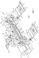
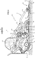
- the equipment 1 comprises a support structure 71 configured to support the equipment 1; a snow-tiller 2 supported by the support structure 71; two tracker devices 3 each forming, two tracks 4 parallel to a direction D1 corresponding to the feed direction of the equipment 1; and a connection structure 19 configured to connect the tracker devices 3 to the tiller 2 in a jointed manner so as to allow a rotation around an axis transverse to the direction D1 of the tracker devices 3 with respect to the tiller 2.
- the connection structure 19 connects the tracker devices 3 to the tiller 2 in a jointed manner with respect to an axis V which is transverse to the direction D1 and transverse to the snow cover N.
- the axis V forms with the snow cover N or with the ground an angle ranging between 60° and 120°; preferably between 60° and 90°, in particular between 75° and 90°.
- the axis V is perpendicular to the snow cover N or to the ground.
- connection structure 19 connects the tracker devices 3 to the tiller 2 in a jointed manner with respect to an axis O, which is transverse to the feed direction D1, in particular perpendicular; and parallel to the snow cover N, in particular not transverse to the snow cover N. Accordingly, the connection structure 19 connects the tracker devices 3 to the tiller 2 in a jointed manner around two axes incident one with the other, preferably perpendicular; in particular the two axes are the axis V and the axis O.
- connection in a jointed manner of two devices around an axis it is meant that the two devices can rotate one with respect to the other around said axis.
- the number of two tracker devices is purely indicative and the present invention relates to a single tracker device or to a machine provided with more than two tracker devices.
- each track 4 is substantially defined by means of a groove having a cross section substantially shaped as an isosceles trapezoid.
- the equipment 1 is towed by a vehicle 8 and is connected to the vehicle 8 by means of the support structure 71.
- the support structure 71 comprises a connection unit 71a so as to be connected to vehicle 8.
- the vehicle 8 is preferably, but not limited to, a tracked vehicle, in particular a snow groomer.
- the tiller 2 comprises a frame 5, a shaft 6, a case 7 arranged around the shaft 6, and a mat 7a made of a flexible material.
- the shaft 6 is mounted in a revolving manner around an axis A and is provided with teeth 9.
- the tiller 2 is supported by the support structure 71.
- the tiller 2 is connected to the support structure 71 by means of the connection structure 19.
- connection structure 19 comprises a joint 19a, a joint 19b, a joint 19c, a joint 19d, an arm 19e which connects the joint 19a and the joint 19b, an arm 19f which connects the joint 19b to the joint 19c, and a guide 10.
- the joint 19a extends parallel to the axis O and allows revolving movements around the axis O.
- the joint 19b extends parallel to the axis O and allows revolving movements around the axis O.
- the joint 19c extends parallel to the axis O and allows revolving movements around the axis O.
- the joint 19d extends along the axis O and allows revolving movements around the axis O.
- the axis O is parallel to the snow cover N or to the ground, i.e. not transverse to the snow cover N or to the ground.
- the axis O is transverse to the feed direction D1 in particular perpendicular to the feed direction D1.
- the frame 5 of the tiller 2 is directly connected to the support structure 71 by means of the joint 19a. Furthermore, the arm 19e is connected to the joint 19a and to the support structure 71. The frame 5 of the tiller 2 is connected to the support structure 71, to the joint 19b of the support structure 71.
- the equipment 1 comprises an actuator 50 which connects the joint 19b to frame 5 of the tiller 2 and is configured to vary its length.
- the actuator 50 is connected to the joint 19b and to the frame 5 at a connecting point 50a differing from the joint 19a. Consequently, the distance between the frame 5 and the joint 19b can selectively vary depending on the variable length of the actuator 50.
- the inclination of the tiller 2 with respect to a snow cover N can be varied by acting on a position of the connecting structure 71 and on the length of the actuator 50 which varies a configuration of the connection structure 19.
- the guide 10 of the connection structure 19 is substantially parallel to the axis A and/or to the axis O.
- the two tracker devices 3 are mounted in a sliding manner along the guide 10.
- the guide 10 is connected by means of an arm 10a to the joint 19c and by means of an arm 10b to the joint 19d.
- the guide 10 is connected to the tiller 2 in the joint 19d.
- the guide 10 is connected to the frame 5 of the tiller 2 by means of the joint 19d of the connection structure 19.
- each tracker device 3 comprises a support structure 11, which is coupled to the connection structure 19; an actuator 15; a slide 16; and a tiller 20.
- connection structure 19 comprises a joint SV which develops along the axis V and allows rotations around the axis V.
- the joint SV is arranged between the support structure 11 of the tracker device 3 and the guide 10 of connection structure 19.
- the connection structure 19 comprises two elastic elements 40 arranged between the tracker device 3 and the connection structure 19 so as to force, due to the elastic force exerted by the same and within the limits thereof, the tracker device 3 in a main position.
- the main position is preferably in axis with the feed direction.
- the two elastic elements 40 are arranged between the support structure 11 and the guide 10 from opposite sides with respect to the joint SV.
- the elastic elements 40 are made of an elastomeric material and also have the purpose of acting as a stop device.
- the elastic elements can be made with a spring or other element having an elastic force.
- the elastic elements can also be defined by means of a single elastic element, for example a spring connected between the guide 10 and the support structure 11.
- the springs can be gas, pneumatic, mechanic actuated or of any other type.
- each tracker device 3 is connected to the tiller 2 by means of the connection structure 19 so as to allow a free rotation around the axis O with respect to the tiller 2.
- Each tracker device 3 is connected to the support structure 71 by means of the connection structure 19 so as to allow a free rotation around the axis O with respect to the support structure 71.
- each tracker device 3 is connected to the tiller 2 by means of the connection structure 19, in particular by means of the joint SV, so as to allow a rotation around the axis V with respect to the tiller 2.
- Each tracker device 3 is connected to the support structure 71 by means of the connection structure 19, in particular by means of the joint SV, so as to allow rotation around the axis V with respect to the support structure 71.
- connection structure 19 comprises a slider 13 engaged with the guide 10.
- Each support structure 11 comprises a central body 11a hinged to the slider 13 by means of the joint SV.
- Each support structure 11 comprises an elongated portion 14 hinged to the central body 11a by means of a joint 14a which develops along an axis parallel to the axis O.
- the actuator 15 is arranged between the central body 11a and the elongated portion 14 to selectively arrange the elongated portion 14 in a working position, in which the tracker device 3 is in contact with the snow cover N and creates the tracks 4; and a rest position in which the tracker device 3 is raised from the snow cover N and does not create the tracks 4.
- the actuator 15 controls the rotation of the elongated portion 14 with respect to the central body 11a around the axis O.
- the tracker device 3 is always in the working position.
- the elongated portion 14 is connected to the central body 11a in a joint 14a.
- the joint 14a is secured to the actuator 15.
- the rotation of the elongated portion 14 with respect to the central body 11a is obtained by the intervention of the actuator 15 and is not free.
- the slide 16 is connected to the support structure 11 and is defined by means of a plate having a lower surface 17 flat and slightly curved upwards at the front edge; two track-setters 18, which are connected to the slide 16, protrude downwardly from the lower surface of slide 16 and are arranged at the rear edge of the slide 16.
- the two track-setters 18 define a work surface on which the tracks 4v are formed.
- the work plane is parallel to the snow cover and in use it is superimposed on the snow cover N.
- the axis O is not incident with, in particular is parallel to the work plane.
- the axis V is incident with the work plane, in particular is perpendicular to the work plane.
- the tiller 20 is coupled to the support structure 11.
- the tiller 20 is coupled to the elongated portion 14 by means of an arm 12 in a joint 12a and to the central body 11a of the support structure 11 in a joint 11b.
- the central body 11a is connected to the slider 13.
- the joints 12a and 11b extend along respective axes parallel to the axis O.
- the equipment 1 comprises an actuator 22 which is adapted to move the slider 13 along the guide 10 and to adjust the distance between the tracker devices 3 in a direction transverse to the direction D1.
- the actuator 22 is omitted.
- the tracker device 3 comprises two blades 23 (illustrated in Figure 2 with dashed lines) connected to a frame 20a of the tiller 20.
- the blades 23 are arranged between the tiller 20 and the tiller 2 in this case, each blade 23 is aligned with a track-setter 18.
- the blade 23 has slightly greater dimensions than the size of the track-setters 18 and separates an elongated and continuous portion of snow cover N from the remaining part of the snow cover N.
- the tiller 2 works a wide strip of snow cover N at a reduced depth, whereas the tillers 20 work on strips having a reduced width at a greater depth.
- the separation of the elongated and continuous portion results in a crumbling effect of the elongated and continuous portion which facilitates the forming of the track 4.
- Each track-setter 18 is dragged along an elongated and continuous portion and compresses the snow cover N of said elongated and continuous portion thanks to the compression action exerted by the actuator 15.
- the connection structure 19 defines a jointed quadrilateral for each tracker device 3 which connects the tracker device 3 with the tiller 2 and with the support structure 71.
- the jointed quadrilateral is formed by the joints 19a, 19b, 19c and 19e, by the elements 19e and 19f, by a frame portion 5 of the tiller 2 interposed between the joint 19a and the joint 19d, and by the arms 10a, 10b and the guide 10 interposed between the joint 19c and the joint 19d.
- the joints 19a, 19b, 19c and 19e extend parallel to the axis O and allow rotations around the axis O.
- the connection structure 19 by means of the joint SV allows rotation of the tracker devices 3 comprising the slide 16 and the tiller 20 with respect to the tiller 2 around the axis V.
- the slide 16 and the tiller 20 are connected to each other in a revolving manner around an axis parallel to the axis O which in turn is parallel to the snow cover N.
- the slide 16 and the tiller 20 are connected to each other in a non-revolving manner around the axis V, in other words the revolving movements of the slide 16 and of the tiller 20 around the axis V are integral one with the other.
- the slide 16 and the tiller 20 are integral one with the other around the axis V and are connected in a revolving manner around the axis V with respect to the tiller 2 or to the vehicle 8.
- This allows the slide 16 to form the tracks where the tiller 20 has worked the snow cover N and there is no misalignment between the slide 16 and the tiller 20 whereas a misalignment between slide 16 and tiller 2 or between tiller 20 and tiller 2 is allowed.
- the slide 16 and the tiller 20 can work better in a curved direction and form tracks 4 with better curved profiles with respect to the known art and at the same time ensure that the slide 16 forms the tracks 4 where the tiller 20 has worked the snow cover N.
- the tracker device 3 comprising the tiller 20 and the slide 16 does not make abrupt revolving movements around the axis V due to the elastic elements 40.
- the position of the tiller 2 with respect to the snow cover N can be varied by means of the actuator 50 and/or the position of the support structure 71 without varying the position of the tiller 20 with respect to the snow cover N.
- the position of the tiller 2 can vary from a first operating position to a second operating position based on the position of the support structure 71 and of the actuator 50, but the position of the tiller 20 with respect to the snow cover N does not vary due to the jointed connection around the axis O provided by the connection structure 19.
- the connection structure 19 provides a freely jointed connection around the axis O between the tiller 2, the support structure 71, and the tracker device 3. Consequently, the position of the tracker device 3 is not changed by the position of the tiller 2 and can be adjusted by means of the actuator 15 acting on the elongated portion which is connected to the central body 11a of the support structure 11.
- connection structure 19 provides a jointed connection around the axis O and around the axis V, significantly improving the working of the snow cover N so that the tracker device 3 can perfectly follow the conformation of the snow cover N.
- the equipment 101 denotes a second embodiment of equipment for creating a cross-country ski trail, alternative to the equipment 1.
- the equipment 101 comprises a support structure 171 configured to support the equipment 101; a tiller 2 supported by the support structure 171; four tracker devices 3 (only one visible in Figure 4 ) each forming, two tracks 4 parallel to a direction D1 corresponding to the feed direction of the equipment 1; and a connection structure 119 configured to connect the tracker devices 3 to the tiller 2 in a jointed manner to allow a rotation around an axis transverse to the direction D1 of the tracker devices 3 with respect to the tiller 2.
- connection structure 119 connects the tracker devices 3 to the tiller 2 in a jointed manner with respect to an axis V which is transverse to the direction D1, preferably perpendicular; and transverse to the snow cover N, preferably perpendicular to the snow cover.
- connection structure 119 connects the tracker devices 3 to the tiller 2 in a jointed manner with respect to an axis O which is transverse to the feed direction D1, in particular perpendicular; and parallel to the snow cover N, in particular non-transverse to the snow cover N. Accordingly, the connection structure 119 connects the tracker devices 3 to the tiller 2 in a jointed manner around two axis incident with one another, preferably perpendicular; in particular the two axes are the axis V and the axis O.
- the number of four tracker devices is purely indicative and the present invention refers to any number of tracker devices from one to more than four.
- the equipment 101 is towed by a vehicle 8 (not shown in Figure 4 ) and is connected to vehicle 8 by means of the support structure 171.
- the tiller 2 and the tracker devices 3 of the equipment 101 are made in the same manner as those of the equipment 1 and are illustrated with the same numbers and not further described.
- the equipment 101 differs from the equipment 1 mainly in the connection structure 119.
- the tiller 2 is supported directly by the support structure 171.
- the frame 5 of the tiller 2 is directly connected to the support structure 171 at a connection point.
- the tracker devices 3 are connected to the tiller 2 by means of the connection structure 119 and are not directly connected to the support structure 171. In other words, in the equipment 101, unlike the equipment 1, the tracker devices 3 are only connected to the tiller 2 by means of the connection structure 119.
- connection structure 119 comprises a guide 110; and an elongated element 119f connected along the frame 5 of the tiller 2. Furthermore, the connection structure 119 comprises a joint 119a, a joint 119b and a joint 119c. The joint 119a and the joint 119b are connected to the elongated element 119f of the connection structure 119.
- the joint 119a extends parallel to the axis O and allows revolving movements around the axis O.
- the joint 119b extends along the axis O and allows revolving movements around the axis O.
- the joint 119c extends parallel to the axis O and allows revolving movements around the axis O.
- the equipment 101 comprises an actuator 150 which is interposed between the joint 119a at the joint 119c and connects the same.
- the actuator 150 is selectively adjustable in length, therefore the distance between the joint 110a and the joint 119c is variable.
- the distance between the tiller 2 and the tracker devices 3 can be selectively varied according to the variable length of the actuator 150.
- the inclination of the tiller 2 with respect to a snow cover N can be varied by acting on a position of the support structure 171.
- the guide 110 of the connection structure 119 is substantially parallel to the axis A and/or to the axis O.
- tracker devices 3 are mounted in a sliding manner.
- the guide 110 is connected, by means of an arm 110a, to the joint 119c in and from an arm 110b to the joint 119b.
- the guide 110 is connected to the tiller 2 directly by means of the joint 119b and by means of the actuator 150 by means of the joint 119c.
- the guide 110 is only connected to the frame 5 of the tiller 2.
- each tracker device 3 is connected to the tiller 2 by means of the connection structure 119 so as to allow a free rotation around the axis O and around the axis V with respect to the tiller 2.
- connection structure 119 comprises a joint SV (equal to the joint SV of the connection structure 19) which extends along the axis V and allows rotations around the axis V.
- connection structure 119 comprises two elastic devices arranged between the tracker 3 and the connection structure 19 and arranged on opposite sides with respect to the joint SV as in the case of the connection structure 19.
- connection structure 119 defines a three-sided structure, in which the length of one of the sides is variable for each tracker device 3 that connects the tracker device 3 with the tiller 2 by means of the guide 110.
- the three-sided structure is formed by the joints 119a, 119b, 119c, by the elements 119f, by the guide 110, by the arms 110a and 110b of the guide 110, and by the actuator 150.
- each tracker device 3 is connected to the tiller 2 by means of the connection structure 119 so as to allow revolving movements around the axis O, based on the position of the actuator 150, due to the joints 119a, 119b and 119c.
- each tracker device 3 is connected to the tiller 2 by means of the connection structure 119 so as to allow revolving movements around the axis V by means of the joint SV.
- the tiller 20 and the slide 16 are connected in a revolving manner around the axis O and in a non-revolving manner one with the other around the axis V.
- the revolving movements of the slide 16 and of the tiller 20 around the axis V are integral with each other.
- the slide 16 and the tiller 20 can perform revolving movements around the axis V with respect to the tiller 2 of the equipment 101.
- the position of the tiller 2 with respect to the snow cover N can be varied due the actuator 150, without changing the position of the tiller 20 with respect to the snow cover N.
- the position of the tiller 2 can vary from a first operating position to a second operating position, but the position of the tiller 20 with respect to the snow cover N does not vary due to the variation of the length of the actuator 150 which compensates for the variation in the position of the tiller 2.
- the connection structure 119 provides a jointed connection between the tiller 2 and the tracker device 3 around the axis O, based on the position of the actuator 150, and around the axis V. The distance of the tracker device 3 from the snow cover N, consequently, is not changed by the position of the tiller 2 and can be adjusted by means of the actuator 15 acting on the elongated portion 14 which is connected to the slider 13 of the support structure 11.
- the equipment 101 comprises a control unit which acts on the actuator 150 to adjust the length of the actuator 150 and on the support structure 171 for the position of the support structure 171 and consequently the position of the tiller 2.
- the movement of the support structure 171 and the movement of the actuator 150 are controlled by the control unit synchronously to ensure that when the position of the support structure 171 varies, in order to vary the position of the tiller 2, the position of the tracker device 3 does not vary.
- the control unit which simultaneously controls both the position of the support structure 171 and the actuator 150 the position of the tracker device 3 is independent of the position of the tiller 2.
- the equipment 201 denotes a third embodiment of equipment for creating a cross-country ski trail, as an alternative to the equipment 1.
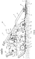
- the equipment 201 comprises a support structure 271 configured to support the equipment 201; a snow-tiller 2 supported by the support structure 271; Two tracker devices 3 (only one is visible in Figure 5 ) each forming, two tracks 4 parallel to a direction D1 corresponding to the feed direction of the equipment 1; and a connection structure 219 configured to connect the tracker devices 3 to the tiller 2 in a jointed manner so as to allow a rotation around an axis transverse to the direction D1 of the tracker devices 3 with respect to the tiller 2.
- connection structure 219 connects the tracker devices 3 to the tiller 2 in a jointed manner with respect to an axis V which is transverse to the direction D1, preferably perpendicular; and transverse to the snow cover N, preferably perpendicular to the snow cover N.
- connection structure 219 connects the tracker devices 3 to the tiller 2 in a non-jointed manner around the axis A by means of the arm 210b.
- the equipment 201 is towed by a vehicle 8 (not shown in Figure 5 ) and is connected to the vehicle 8 by the support structure 271.
- the tiller 2 and the tracker devices 3 of the equipment 201 are made in the same manner as those of the equipment 1 and are illustrated with the same numbers and not further described.
- the equipment 201 differs from the equipment 1 mainly in connection structure 219.
- the tiller 2 is supported directly by the support structure 271.
- the frame 5 of the tiller 2 is directly connected to the support structure 271 at a connection point.
- the tracker devices 3 are connected to the tiller 2 by means of the connection structure 219 and are not directly connected to the support structure 271.
- the tracker devices 3 are only connected to the tiller 2 by means of the connection structure 219.
- connection structure 219 comprises a guide 210.
- connection structure 219 comprises a joint 219a, a joint 219b, an arm 19e which connects the joint 19a and the joint 19b, and the guide 210.
- the joint 219a extends parallel to an axis O and allows revolving movements around the axis O.
- the joint 219b extends parallel to the axis O and allows revolving movements around the axis O.
- the axis O is parallel to the snow cover N or the ground, i.e. is not transverse to the snow cover N or to the ground.
- the axis O is transverse to the feed direction D1 in particular perpendicular to the feed direction D1.
- the frame 5 of the tiller 2 is directly connected to the support structure 71 by means of the joint 219a.
- the arm 219e is connected to the joint 219a and to the support structure 271.
- the frame 5 of the tiller 2 is connected to the support structure 271 to the joint 219b of the support structure 271.
- the equipment 1 comprises an actuator 250 which connects the joint 219b to the frame 5 of the tiller 2 and is configured to vary its length.
- the actuator 250 is connected to the joint 219b and to the frame 5 at a connection point 250a other than the joint 219a. Consequently, the distance between the frame 5 and the joint 219b can vary according to the variable length of the actuator 250.
- the inclination of the tiller 2 with respect to a snow cover N can be varied by acting on a position of the support structure 271 and on the length of the actuator 250 which varies a configuration of the connection structure 219.
- the guide 210 of the connection structure 219 is substantially parallel to the axis A and/or the axis O.
- the two tracker devices 3 are mounted in a sliding manner along the guide 210.
- the guide 10 is also connected by means of an arm 210b of the connection structure 219 to the tiller 2.
- the guide 210 is connected to the frame 5 of the tiller 2 by means of the arm 210b of the connection structure 19 in an integral manner.
- each tracker device 3 is connected to the tiller 2 by means of the connection structure 119 so as to allow a free rotation around the axis V with respect to the tiller 2.
- connection structure 119 comprises a joint SV (equal to the joint SV of the connection structure 19) which develops along the axis V and allows rotations around the axis V.
- connection structure 219 comprises two elastic devices arranged between the tracker 3 and the connection structure 219 and arranged on opposite sides with respect to the joint SV as in the case of the connection structure 19.
- each tracker device 3 is connected to the tiller 2 by means of the connection structure 219 so as to allow revolving movements around the axis V, due to the joint SV.
- the tiller 20 and the slide 16 are connected to each other in a revolving manner around the axis O and to each other in a non-revolving manner around the axis V.
- the revolving movements of the slide 16 and of the tiller 20 around the axis V are integral one with the other.
- the slide 16 and the tiller 20 can perform integral and revolving movements together around the axis V with respect to the tiller 2 of the equipment 201.
- the tiller 20 and the slide 16 in a curved direction define the tracks 4 having improved profiles with respect to the known art and is ensured that the slide 16 works a portion of the snow cover N which has been previously worked by the tiller 20.
- the slide 16 defines a work plane (corresponding to a plane on which it forms the tracks 4).
- the axis V is incident with the work plane defined by the slide 16.
- the axis V forms with the work plane an angle of between 60° and 120°; preferably between 60° and 90°, in particular between 75° and 90°.
Landscapes
- Engineering & Computer Science (AREA)
- Architecture (AREA)
- Civil Engineering (AREA)
- Structural Engineering (AREA)
- Soil Working Implements (AREA)
- Cleaning Of Streets, Tracks, Or Beaches (AREA)
- Lifting Devices For Agricultural Implements (AREA)
- Heterocyclic Carbon Compounds Containing A Hetero Ring Having Oxygen Or Sulfur (AREA)
Claims (15)
- Ausrüstung zur Erzeugen einer Langlaufloipe für ein Fahrzeug, wobei die Ausrüstung eine erste Fräse (2), eine Tracker-Vorrichtung (3) zum Bilden von Spuren (4) in einer Schneedecke (N), und eine Verbindungsstruktur (19; 119; 219) zum Koppeln der Tracker-Vorrichtung (3) mit der ersten Fräse (2) umfasst;
wobei die Verbindungsstruktur (19; 119) und die Tracker-Vorrichtung (3) auf zusammengefügte bzw. gelenkige Weise miteinander um eine erste Achse (V) verbunden sind, die mit der Schneedecke (N) oder dem Boden zusammenfällt, und zwar vorzugsweise quer zu einer Vorschubrichtung (D1); wobei die Ausrüstung eine Stütz- bzw. Trägerstruktur (71; 171; 271) umfasst, die konfiguriert ist, die Ausrüstung (1; 101; 201) mit dem Fahrzeug zu verbinden; wobei die Verbindungsstruktur (19, 119, 219) mit der ersten Fräse (2) verbunden ist, wobei insbesondere die Verbindungsstruktur (19, 119, 219) die Tracker-Vorrichtung (3) mit der ersten Fräse (2) auf zusammengefügte bzw. gelenkige Weise um die erste Achse (V) verbindet,
dadurch gekennzeichnet, dass die Verbindungsstruktur (19; 119; 219) eine zweite Verbindung bzw. ein zweites Gelenk (19a; 119a; 219a) umfasst, die bzw. das sich parallel zu einer zweiten Achse (O) parallel zu der Schneedecke (N) erstreckt, wobei die Verbindungsstruktur (19; 119; 219) mit der Trägerstruktur (71; 171; 271) mittels des zweiten Gelenks (19a; 119a; 219a) auf rotierende Weise um die zweite Achse (O) verbunden ist, wobei die Tracker-Vorrichtung (3) mittels der Verbindungsstruktur (19) mit der Fräse (2) verbunden ist, um eine freie Drehung um die zweite Achse (O) in Bezug auf die Fräse (2) zu erlauben, und die Tracker-Vorrichtung (3) mittels der Verbindungsstruktur (19) mit der Trägerstruktur (71) verbunden ist, um eine freie Drehung um die zweite Achse (O) in Bezug auf die Trägerstruktur zu erlauben. - Ausrüstung nach Anspruch 1, wobei die erste Achse (V) mit der Schneedecke (N) oder mit dem Boden einen Winkel zwischen 60° und 120°, vorzugsweise zwischen 60° und 90°, insbesondere zwischen 75° und 90° definiert.
- Ausrüstung gemäß einem der vorhergehenden Ansprüche, wobei die Tracker-Vorrichtung (3) mit der Verbindungsstruktur (19; 119; 219) mittels eine erste Verbindung bzw. ein erstes Gelenk (SV) verbunden ist, die bzw. das sich entlang der ersten Achse (V) entwickelt und Drehbewegungen um die erste Achse (V) erlaubt.
- Ausrüstung gemäß einem der vorhergehenden Ansprüche, wobei die Verbindungsstruktur (19; 119; 219) zumindest ein elastisches Element (40) umfasst, das zwischen der Verbindungsstruktur (19; 119; 219) und der Tracker-Vorrichtung (3) angeordnet ist, um die Tracker-Vorrichtung (3) in eine erste Position zu zwingen.
- Ausrüstung nach Anspruch 4, wobei die Verbindungsstruktur (19; 119; 219) ein festes Element (10) umfasst, wobei die Tracker-Vorrichtung (3) eine Stütz- bzw. Trägerstruktur (11) aufweist, die auf zusammengefügte bzw. gelenkige Weise mit dem festen Element (10) um die erste Achse (V) verbunden ist, wobei das elastische Element (40) zwischen dem festen Element (10) und der Trägerstruktur (11) angeordnet ist, wobei vorzugsweise die Verbindungsstruktur (19; 119; 219) ein weiteres elastisches Element (40) umfasst und die beiden elastischen Elemente (40) auf gegenüberliegenden bzw. entgegengesetzten Seiten desersten Gelenks (SV) untergebracht sind.
- Ausrüstung nach einem der vorhergehenden Ansprüche, wobei die Tracker-Vorrichtung (3) einen Schlitten (16), der konfiguriert ist, Spuren (4) in der Schneedecke (N) zu bilden, und eine zweite Fräse (20) umfasst, die miteinander auf nicht drehende Weise um die erste Achse (V) verbunden sind.
- Ausrüstung nach Anspruch 6, wobei der Schlitten (16) und die zweite Fräse (20) auf drehende Weise um eine zweite Achse (O) miteinander verbunden sind, die mit der ersten Achse (V) zusammenfällt, wobei die zweiten Achse (O) vorzugsweise parallel zu der Schneedecke (N) ist.
- Ausrüstung nach einem der vorhergehenden Ansprüche, umfassend die erste Fräse (2), wobei die Verbindungsstruktur (19; 119; 219) mit der ersten Fräse (2) verbunden ist, wobei insbesondere die Verbindungsstruktur (19; 119; 219) die Tracker-Vorrichtung (3) auf zusammengefügte bzw. gelenkige Weise mit der ersten Fräse (2) um eine zweite Achse (O) verbindet, die mit der ersten Achse (V) zusammenfällt, wobei die zweite Achse vorzugsweise parallel zu der Schneedecke (N) ist.
- Ausrüstung nach einem der vorhergehenden Ansprüche, wobei die Verbindungsstruktur (19; 119; 219) eine dritte Verbindung bzw. ein drittes Gelenk (19d; 119b) umfasst, die bzw. das sich entlang einer zweiten Achse (O) erstreckt, die mit der ersten Achse (V) zusammenfällt und vorzugsweise parallel zu der Schneedecke (N) ist, um die Ausrüstung (1) mit dem Fahrzeug auf drehende Weise um die zweite Achse (O) zu verbinden.
- Ausrüstung nach einem der vorhergehenden Ansprüche, wobei die Tracker-Vorrichtung (3) eine Stütz- bzw. Trägerstruktur (11) und einen Schlitten (16) umfasst, wobei die Trägerstruktur (11) mit der ersten Fräse (2) oder mit dem Fahrzeug mittels der Verbindungsstruktur (19; 119; 219) auf drehende Weise um die erste Achse (V) verbunden ist.
- Ausrüstung nach Anspruch 10, wobei der Schlitten (16) mit einem länglichen Abschnitt (14) der Trägerstruktur (11) verbunden ist, wobei der längliche Abschnitt (14) mit einem Körper (11a) der Trägerstruktur (11) über ein viertes Gelenk (14a), das sich parallel zu einer zweiten Achse (O) entwickelt, die mit der ersten Achse (V) zusammenfällt, und mittels eines Aktors (15) verbunden ist, um die Position des länglichen Körpers (14) in Bezug auf den Körper (13) auf selektiv einstellbare Weise zu sichern.
- Ausrüstung nach einem der vorhergehenden Ansprüche, umfassend die erste Fräse (2), wobei die Verbindungsstruktur (219) einen ersten Arm (210b) umfasst, wobei die Tracker-Vorrichtung (3) mit der ersten Fräse (2) mittels der Verbindungsstruktur (219) auf integrale Weise über den ersten Arm (210b) verbunden ist.
- Ausrüstung nach Anspruch 11, umfassend die erste Fräse (2), die einen Rahmen (5) umfasst, wobei die Verbindungsstruktur (19) eine fünfte Verbindung bzw. ein fünftes Gelenk (19b) und einen zweiten Arm (19e) umfasst, der das fünfte Gelenk (19b) mit dem zweiten Gelenk (19a) verbindet; umfassend einen zweiten Aktor (50), wobei der zweite Aktuator (50) eine selektiv einstellbare Länge aufweist, die den Rahmen (5) der Fräse (2) mit dem fünften Gelenk (19b) verbindet, so dass ein Abstand zwischen dem Rahmen (5) und dem fünften Gelenk (19b) selektiv einstellbar ist.
- Ausrüstung nach einem der vorhergehenden Ansprüche, umfassend die erste Fräse (2), wobei die Verbindungsstruktur (19) ein zusammengefügtes bzw. gelenkiges Viereck mit vier Verbindungen bzw. Gelenken (19a, 19b, 19c, 19d) umfasst und die Tracker-Vorrichtung (3) mit der Fräse (2) verbindet, so dass sich die Tracker-Vorrichtung (3) frei um eine zweite Achse (O) drehen kann, die mit der ersten Achse (V) zusammenfällt und vorzugsweise parallel zu der Schneedecke (N) ist, und zwar in Bezug auf die Fräse (3), um eine Position in Bezug auf die Schneedecke (N) einzunehmen, die unabhängig von der Position der Fräse (2) in Bezug auf die Schneedecke (N) ist.
- Ausrüstung nach Anspruch 1 und 13, umfassend die erste Fräse (2), wobei die Verbindungsstruktur (119) einen dritten Aktor (150) mit einer selektiv einstellbaren Länge umfasst, und wobei die Verbindungsstruktur (119) eine sechste Verbindung bzw. ein sechstes Gelenk (119c) umfasst, die bzw. das mit dem zweiten Gelenk (119a) mittels des Aktors (150) verbunden ist, so dass der Abstand zwischen dem zweiten Gelenk (119a) und dem sechsten Gelenk (119c) selektiv einstellbar ist, wobei das sechste Gelenk (119c) mit der Tracker-Vorrichtung (3) über das erste Gelenk (SV) verbunden ist.
Applications Claiming Priority (2)
| Application Number | Priority Date | Filing Date | Title |
|---|---|---|---|
| ITUA2016A002388A ITUA20162388A1 (it) | 2016-04-07 | 2016-04-07 | Apparato per realizzare una pista da sci di fondo |
| PCT/IB2017/052021 WO2017175193A1 (en) | 2016-04-07 | 2017-04-07 | Equipment for creating a cross-country ski trail |
Publications (2)
| Publication Number | Publication Date |
|---|---|
| EP3440264A1 EP3440264A1 (de) | 2019-02-13 |
| EP3440264B1 true EP3440264B1 (de) | 2020-09-09 |
Family
ID=56555523
Family Applications (1)
| Application Number | Title | Priority Date | Filing Date |
|---|---|---|---|
| EP17726146.8A Active EP3440264B1 (de) | 2016-04-07 | 2017-04-07 | Ausrüstung für die erstellung einer langlaufloipe |
Country Status (6)
| Country | Link |
|---|---|
| US (1) | US11066795B2 (de) |
| EP (1) | EP3440264B1 (de) |
| CN (1) | CN107923135B (de) |
| IT (1) | ITUA20162388A1 (de) |
| RU (1) | RU2741113C2 (de) |
| WO (1) | WO2017175193A1 (de) |
Cited By (1)
| Publication number | Priority date | Publication date | Assignee | Title |
|---|---|---|---|---|
| EP4737643A1 (de) | 2024-10-30 | 2026-05-06 | PRINOTH S.p.A. | Schneefräse |
Families Citing this family (4)
| Publication number | Priority date | Publication date | Assignee | Title |
|---|---|---|---|---|
| ITUB20159370A1 (it) * | 2015-12-14 | 2017-06-14 | Prinoth Spa | Apparato per realizzare una pista da sci di fondo |
| IT201800003000A1 (it) * | 2018-02-23 | 2019-08-23 | Prinoth Spa | Fresa da neve e relativo metodo di regolazione |
| IT201900002017A1 (it) * | 2019-02-12 | 2020-08-12 | Prinoth Spa | Fresa da neve per la preparazione di piste da sci |
| IT202000011272A1 (it) | 2020-05-15 | 2021-11-15 | Veicolo battipista e metodo per controllare un veicolo battipista |
Family Cites Families (19)
| Publication number | Priority date | Publication date | Assignee | Title |
|---|---|---|---|---|
| CA1038681A (en) * | 1976-04-05 | 1978-09-19 | Lucien Henrichon | Ski trail forming and conditioning drag |
| US4359831A (en) * | 1980-05-19 | 1982-11-23 | De Lorean Manufacturing Company | Reversibly powered rotary snow tiller |
| DE3333941A1 (de) * | 1983-09-20 | 1985-04-04 | Karl Kässbohrer Fahrzeugwerke GmbH, 7900 Ulm | Fraese |
| DE3333942A1 (de) * | 1983-09-20 | 1985-03-28 | Karl Kässbohrer Fahrzeugwerke GmbH, 7900 Ulm | Schneefahrzeug |
| DE8526773U1 (de) * | 1985-09-19 | 1986-05-15 | Kaltenbach, Viktor, 7750 Konstanz | Vorrichtung zum Herstellen oder Bearbeiten von Skiloipen, Abfahrtspisten od.dgl. |
| AT388308B (de) * | 1985-09-23 | 1989-06-12 | Ranner Dietrich | Spurgeraet fuer langlaufloipen |
| US4788783A (en) * | 1987-03-24 | 1988-12-06 | Bachler Anton R | Ski-track forming apparatus |
| US4815223A (en) * | 1988-01-04 | 1989-03-28 | West Mountain Sales, Inc. | Snow grooming vehicle and attachments |
| IT1248841B (it) * | 1990-06-13 | 1995-01-30 | Prinoth Spa | Dispositivo per tracciare piste da fondo, combinato con un veicolo da neve |
| US5142800A (en) * | 1991-12-27 | 1992-09-01 | Logan Manufacturing Company | Snow groomer tow frame alignment device |
| DE9217472U1 (de) * | 1992-12-21 | 1993-02-25 | Karl Kässbohrer Fahrzeugwerke GmbH, 7900 Ulm | Pistenpflegevorrichtung |
| DE29723018U1 (de) * | 1997-12-31 | 1999-04-29 | Kässbohrer Geländefahrzeug AG, 89250 Senden | Pistenpflegegerät |
| WO2001044582A1 (en) * | 1999-12-17 | 2001-06-21 | Bombardier Inc. | Snow groomer having an improved variable geometry tiller assembly |
| US20030154633A1 (en) * | 2000-03-22 | 2003-08-21 | Jean-Philippe Lassonde | Snow groomer with a variable snowchamber tiller assembly |
| DE10253412A1 (de) * | 2002-11-08 | 2004-05-27 | Kässbohrer Geländefahrzeug AG | Verfahren zur Steuerung eines Pistenpflegefahrzeugs und Pistenpflegefahrzeug |
| DE10261944A1 (de) * | 2002-12-17 | 2004-07-01 | Kässbohrer Geländefahrzeug AG | Verfahren zur Steuerung einer Seilwinde eines Pistenpflegefahrzeugs und Pistenpflegefahrzeug |
| DE102005040222A1 (de) * | 2005-08-17 | 2007-02-22 | Kässbohrer Geländefahrzeug AG | Loipenspurgerät und Pistenpflegefahrzeug mit wenigstens einem derartigen Loipenspurgerät |
| IT1403595B1 (it) | 2010-12-21 | 2013-10-31 | Rolic Invest Sarl | Metodo per formare tracce in un manto nevoso, in particolare per realizzare una pista di sci di fondo, e relativo dispositivo tracciatore |
| ITUA20162397A1 (it) * | 2016-04-07 | 2017-10-07 | Prinoth Spa | Apparato idraulico per alimentare un gruppo di dispositivi tracciatori per un veicolo cingolato; il gruppo di dispositivi tracciatori e il veicolo cingolato |
-
2016
- 2016-04-07 IT ITUA2016A002388A patent/ITUA20162388A1/it unknown
-
2017
- 2017-04-07 WO PCT/IB2017/052021 patent/WO2017175193A1/en not_active Ceased
- 2017-04-07 US US16/090,971 patent/US11066795B2/en active Active
- 2017-04-07 EP EP17726146.8A patent/EP3440264B1/de active Active
- 2017-04-07 CN CN201780002845.6A patent/CN107923135B/zh active Active
- 2017-04-07 RU RU2018138925A patent/RU2741113C2/ru active
Non-Patent Citations (1)
| Title |
|---|
| None * |
Cited By (1)
| Publication number | Priority date | Publication date | Assignee | Title |
|---|---|---|---|---|
| EP4737643A1 (de) | 2024-10-30 | 2026-05-06 | PRINOTH S.p.A. | Schneefräse |
Also Published As
| Publication number | Publication date |
|---|---|
| CA3020062A1 (en) | 2017-10-12 |
| US20190119872A1 (en) | 2019-04-25 |
| EP3440264A1 (de) | 2019-02-13 |
| CN107923135B (zh) | 2021-07-02 |
| US11066795B2 (en) | 2021-07-20 |
| CN107923135A (zh) | 2018-04-17 |
| ITUA20162388A1 (it) | 2017-10-07 |
| RU2018138925A (ru) | 2020-05-12 |
| RU2741113C2 (ru) | 2021-01-22 |
| WO2017175193A1 (en) | 2017-10-12 |
| RU2018138925A3 (de) | 2020-07-24 |
Similar Documents
| Publication | Publication Date | Title |
|---|---|---|
| US11066795B2 (en) | Equipment for creating a cross-country ski trail | |
| US5743032A (en) | Plough blade arrangement | |
| CA2615310A1 (en) | Single disc furrow opener with walking beam | |
| US9609796B2 (en) | Grading tools for work machines and operation thereof | |
| EP3390728B1 (de) | Vorrichtung zur herstellung einer langlaufloipe | |
| CA1156092A (en) | Track working machine for distributing and shaping the ballast in a railroad bed | |
| EP3924552B1 (de) | Schneefräse für die vorbereitung von skipisten | |
| CA3020062C (en) | Equipment for creating a cross-country ski trail | |
| CN110184986B (zh) | 犁雪机及其调节方法 | |
| US5940995A (en) | Apparatus for forming a snow half-pipe | |
| CN110122010B (zh) | 一种小麦断根分层施肥机断根装置 | |
| JP2003304706A (ja) | 整畦機 | |
| US12426539B2 (en) | Cutting mechanism with leaf spring assembly as a cutting element support | |
| EP2522779B1 (de) | Verbesserter Schneepflug zum Schneeräumen | |
| EP1973394B1 (de) | Verbesserungen bei landwirtschaftlichen geräten und diese betreffende | |
| CN112930830B (zh) | 一种马铃薯挖掘铲的自动调节组件 | |
| SE502565C2 (sv) | Snöröjningsredskap | |
| US79030A (en) | John a | |
| FI67285B (fi) | Plog foer samtidig ploejning och alvploejning | |
| JP3213251B2 (ja) | 刈取収穫機の刈取前処理装置支持構造 | |
| JP2527096Y2 (ja) | コンバイン等の刈取装置 | |
| RU2149533C1 (ru) | Щуп-стеблеподъемник жатки зерноуборочного комбайна | |
| JP2008113616A (ja) | バリカン型刈取装置 | |
| IT201900019990A1 (it) | Gruppo pala per veicolo cingolato, in particolare battipista, e veicolo battipista |
Legal Events
| Date | Code | Title | Description |
|---|---|---|---|
| STAA | Information on the status of an ep patent application or granted ep patent |
Free format text: STATUS: UNKNOWN |
|
| STAA | Information on the status of an ep patent application or granted ep patent |
Free format text: STATUS: THE INTERNATIONAL PUBLICATION HAS BEEN MADE |
|
| PUAI | Public reference made under article 153(3) epc to a published international application that has entered the european phase |
Free format text: ORIGINAL CODE: 0009012 |
|
| STAA | Information on the status of an ep patent application or granted ep patent |
Free format text: STATUS: REQUEST FOR EXAMINATION WAS MADE |
|
| 17P | Request for examination filed |
Effective date: 20181012 |
|
| AK | Designated contracting states |
Kind code of ref document: A1 Designated state(s): AL AT BE BG CH CY CZ DE DK EE ES FI FR GB GR HR HU IE IS IT LI LT LU LV MC MK MT NL NO PL PT RO RS SE SI SK SM TR |
|
| AX | Request for extension of the european patent |
Extension state: BA ME |
|
| RIN1 | Information on inventor provided before grant (corrected) |
Inventor name: UNTERHOLZNER, MARKUS Inventor name: SAGGIORATO, LUCA Inventor name: BAIER, STEFAN |
|
| DAV | Request for validation of the european patent (deleted) | ||
| DAX | Request for extension of the european patent (deleted) | ||
| STAA | Information on the status of an ep patent application or granted ep patent |
Free format text: STATUS: EXAMINATION IS IN PROGRESS |
|
| 17Q | First examination report despatched |
Effective date: 20190924 |
|
| GRAP | Despatch of communication of intention to grant a patent |
Free format text: ORIGINAL CODE: EPIDOSNIGR1 |
|
| STAA | Information on the status of an ep patent application or granted ep patent |
Free format text: STATUS: GRANT OF PATENT IS INTENDED |
|
| INTG | Intention to grant announced |
Effective date: 20200407 |
|
| GRAS | Grant fee paid |
Free format text: ORIGINAL CODE: EPIDOSNIGR3 |
|
| GRAA | (expected) grant |
Free format text: ORIGINAL CODE: 0009210 |
|
| STAA | Information on the status of an ep patent application or granted ep patent |
Free format text: STATUS: THE PATENT HAS BEEN GRANTED |
|
| AK | Designated contracting states |
Kind code of ref document: B1 Designated state(s): AL AT BE BG CH CY CZ DE DK EE ES FI FR GB GR HR HU IE IS IT LI LT LU LV MC MK MT NL NO PL PT RO RS SE SI SK SM TR |
|
| REG | Reference to a national code |
Ref country code: GB Ref legal event code: FG4D |
|
| REG | Reference to a national code |
Ref country code: AT Ref legal event code: REF Ref document number: 1311728 Country of ref document: AT Kind code of ref document: T Effective date: 20200915 Ref country code: CH Ref legal event code: EP |
|
| REG | Reference to a national code |
Ref country code: IE Ref legal event code: FG4D |
|
| REG | Reference to a national code |
Ref country code: DE Ref legal event code: R096 Ref document number: 602017023300 Country of ref document: DE |
|
| REG | Reference to a national code |
Ref country code: CH Ref legal event code: NV Representative=s name: HEPP WENGER RYFFEL AG, CH |
|
| REG | Reference to a national code |
Ref country code: FI Ref legal event code: FGE |
|
| REG | Reference to a national code |
Ref country code: SE Ref legal event code: TRGR |
|
| REG | Reference to a national code |
Ref country code: LT Ref legal event code: MG4D |
|
| PG25 | Lapsed in a contracting state [announced via postgrant information from national office to epo] |
Ref country code: GR Free format text: LAPSE BECAUSE OF FAILURE TO SUBMIT A TRANSLATION OF THE DESCRIPTION OR TO PAY THE FEE WITHIN THE PRESCRIBED TIME-LIMIT Effective date: 20201210 Ref country code: HR Free format text: LAPSE BECAUSE OF FAILURE TO SUBMIT A TRANSLATION OF THE DESCRIPTION OR TO PAY THE FEE WITHIN THE PRESCRIBED TIME-LIMIT Effective date: 20200909 Ref country code: LT Free format text: LAPSE BECAUSE OF FAILURE TO SUBMIT A TRANSLATION OF THE DESCRIPTION OR TO PAY THE FEE WITHIN THE PRESCRIBED TIME-LIMIT Effective date: 20200909 Ref country code: BG Free format text: LAPSE BECAUSE OF FAILURE TO SUBMIT A TRANSLATION OF THE DESCRIPTION OR TO PAY THE FEE WITHIN THE PRESCRIBED TIME-LIMIT Effective date: 20201209 |
|
| REG | Reference to a national code |
Ref country code: NO Ref legal event code: T2 Effective date: 20200909 |
|
| REG | Reference to a national code |
Ref country code: NL Ref legal event code: MP Effective date: 20200909 |
|
| PG25 | Lapsed in a contracting state [announced via postgrant information from national office to epo] |
Ref country code: LV Free format text: LAPSE BECAUSE OF FAILURE TO SUBMIT A TRANSLATION OF THE DESCRIPTION OR TO PAY THE FEE WITHIN THE PRESCRIBED TIME-LIMIT Effective date: 20200909 Ref country code: RS Free format text: LAPSE BECAUSE OF FAILURE TO SUBMIT A TRANSLATION OF THE DESCRIPTION OR TO PAY THE FEE WITHIN THE PRESCRIBED TIME-LIMIT Effective date: 20200909 Ref country code: PL Free format text: LAPSE BECAUSE OF FAILURE TO SUBMIT A TRANSLATION OF THE DESCRIPTION OR TO PAY THE FEE WITHIN THE PRESCRIBED TIME-LIMIT Effective date: 20200909 |
|
| PG25 | Lapsed in a contracting state [announced via postgrant information from national office to epo] |
Ref country code: PT Free format text: LAPSE BECAUSE OF FAILURE TO SUBMIT A TRANSLATION OF THE DESCRIPTION OR TO PAY THE FEE WITHIN THE PRESCRIBED TIME-LIMIT Effective date: 20210111 Ref country code: RO Free format text: LAPSE BECAUSE OF FAILURE TO SUBMIT A TRANSLATION OF THE DESCRIPTION OR TO PAY THE FEE WITHIN THE PRESCRIBED TIME-LIMIT Effective date: 20200909 Ref country code: CZ Free format text: LAPSE BECAUSE OF FAILURE TO SUBMIT A TRANSLATION OF THE DESCRIPTION OR TO PAY THE FEE WITHIN THE PRESCRIBED TIME-LIMIT Effective date: 20200909 Ref country code: SM Free format text: LAPSE BECAUSE OF FAILURE TO SUBMIT A TRANSLATION OF THE DESCRIPTION OR TO PAY THE FEE WITHIN THE PRESCRIBED TIME-LIMIT Effective date: 20200909 Ref country code: EE Free format text: LAPSE BECAUSE OF FAILURE TO SUBMIT A TRANSLATION OF THE DESCRIPTION OR TO PAY THE FEE WITHIN THE PRESCRIBED TIME-LIMIT Effective date: 20200909 |
|
| PG25 | Lapsed in a contracting state [announced via postgrant information from national office to epo] |
Ref country code: IS Free format text: LAPSE BECAUSE OF FAILURE TO SUBMIT A TRANSLATION OF THE DESCRIPTION OR TO PAY THE FEE WITHIN THE PRESCRIBED TIME-LIMIT Effective date: 20210109 Ref country code: ES Free format text: LAPSE BECAUSE OF FAILURE TO SUBMIT A TRANSLATION OF THE DESCRIPTION OR TO PAY THE FEE WITHIN THE PRESCRIBED TIME-LIMIT Effective date: 20200909 Ref country code: AL Free format text: LAPSE BECAUSE OF FAILURE TO SUBMIT A TRANSLATION OF THE DESCRIPTION OR TO PAY THE FEE WITHIN THE PRESCRIBED TIME-LIMIT Effective date: 20200909 |
|
| REG | Reference to a national code |
Ref country code: DE Ref legal event code: R097 Ref document number: 602017023300 Country of ref document: DE |
|
| PG25 | Lapsed in a contracting state [announced via postgrant information from national office to epo] |
Ref country code: SK Free format text: LAPSE BECAUSE OF FAILURE TO SUBMIT A TRANSLATION OF THE DESCRIPTION OR TO PAY THE FEE WITHIN THE PRESCRIBED TIME-LIMIT Effective date: 20200909 |
|
| REG | Reference to a national code |
Ref country code: AT Ref legal event code: UEP Ref document number: 1311728 Country of ref document: AT Kind code of ref document: T Effective date: 20200909 |
|
| PLBE | No opposition filed within time limit |
Free format text: ORIGINAL CODE: 0009261 |
|
| STAA | Information on the status of an ep patent application or granted ep patent |
Free format text: STATUS: NO OPPOSITION FILED WITHIN TIME LIMIT |
|
| 26N | No opposition filed |
Effective date: 20210610 |
|
| PG25 | Lapsed in a contracting state [announced via postgrant information from national office to epo] |
Ref country code: SI Free format text: LAPSE BECAUSE OF FAILURE TO SUBMIT A TRANSLATION OF THE DESCRIPTION OR TO PAY THE FEE WITHIN THE PRESCRIBED TIME-LIMIT Effective date: 20200909 Ref country code: DK Free format text: LAPSE BECAUSE OF FAILURE TO SUBMIT A TRANSLATION OF THE DESCRIPTION OR TO PAY THE FEE WITHIN THE PRESCRIBED TIME-LIMIT Effective date: 20200909 |
|
| PG25 | Lapsed in a contracting state [announced via postgrant information from national office to epo] |
Ref country code: MC Free format text: LAPSE BECAUSE OF FAILURE TO SUBMIT A TRANSLATION OF THE DESCRIPTION OR TO PAY THE FEE WITHIN THE PRESCRIBED TIME-LIMIT Effective date: 20200909 |
|
| GBPC | Gb: european patent ceased through non-payment of renewal fee |
Effective date: 20210407 |
|
| PG25 | Lapsed in a contracting state [announced via postgrant information from national office to epo] |
Ref country code: LU Free format text: LAPSE BECAUSE OF NON-PAYMENT OF DUE FEES Effective date: 20210407 |
|
| REG | Reference to a national code |
Ref country code: BE Ref legal event code: MM Effective date: 20210430 |
|
| PG25 | Lapsed in a contracting state [announced via postgrant information from national office to epo] |
Ref country code: GB Free format text: LAPSE BECAUSE OF NON-PAYMENT OF DUE FEES Effective date: 20210407 |
|
| PG25 | Lapsed in a contracting state [announced via postgrant information from national office to epo] |
Ref country code: IE Free format text: LAPSE BECAUSE OF NON-PAYMENT OF DUE FEES Effective date: 20210407 |
|
| PG25 | Lapsed in a contracting state [announced via postgrant information from national office to epo] |
Ref country code: IS Free format text: LAPSE BECAUSE OF FAILURE TO SUBMIT A TRANSLATION OF THE DESCRIPTION OR TO PAY THE FEE WITHIN THE PRESCRIBED TIME-LIMIT Effective date: 20210109 |
|
| PG25 | Lapsed in a contracting state [announced via postgrant information from national office to epo] |
Ref country code: BE Free format text: LAPSE BECAUSE OF NON-PAYMENT OF DUE FEES Effective date: 20210430 |
|
| P01 | Opt-out of the competence of the unified patent court (upc) registered |
Effective date: 20230518 |
|
| PG25 | Lapsed in a contracting state [announced via postgrant information from national office to epo] |
Ref country code: NL Free format text: LAPSE BECAUSE OF NON-PAYMENT OF DUE FEES Effective date: 20200923 Ref country code: CY Free format text: LAPSE BECAUSE OF FAILURE TO SUBMIT A TRANSLATION OF THE DESCRIPTION OR TO PAY THE FEE WITHIN THE PRESCRIBED TIME-LIMIT Effective date: 20200909 |
|
| PG25 | Lapsed in a contracting state [announced via postgrant information from national office to epo] |
Ref country code: HU Free format text: LAPSE BECAUSE OF FAILURE TO SUBMIT A TRANSLATION OF THE DESCRIPTION OR TO PAY THE FEE WITHIN THE PRESCRIBED TIME-LIMIT; INVALID AB INITIO Effective date: 20170407 |
|
| PGFP | Annual fee paid to national office [announced via postgrant information from national office to epo] |
Ref country code: FI Payment date: 20230424 Year of fee payment: 7 |
|
| PG25 | Lapsed in a contracting state [announced via postgrant information from national office to epo] |
Ref country code: MK Free format text: LAPSE BECAUSE OF FAILURE TO SUBMIT A TRANSLATION OF THE DESCRIPTION OR TO PAY THE FEE WITHIN THE PRESCRIBED TIME-LIMIT Effective date: 20200909 |
|
| PG25 | Lapsed in a contracting state [announced via postgrant information from national office to epo] |
Ref country code: TR Free format text: LAPSE BECAUSE OF FAILURE TO SUBMIT A TRANSLATION OF THE DESCRIPTION OR TO PAY THE FEE WITHIN THE PRESCRIBED TIME-LIMIT Effective date: 20200909 |
|
| PG25 | Lapsed in a contracting state [announced via postgrant information from national office to epo] |
Ref country code: MT Free format text: LAPSE BECAUSE OF FAILURE TO SUBMIT A TRANSLATION OF THE DESCRIPTION OR TO PAY THE FEE WITHIN THE PRESCRIBED TIME-LIMIT Effective date: 20200909 |
|
| PG25 | Lapsed in a contracting state [announced via postgrant information from national office to epo] |
Ref country code: FI Free format text: LAPSE BECAUSE OF NON-PAYMENT OF DUE FEES Effective date: 20240407 |
|
| PG25 | Lapsed in a contracting state [announced via postgrant information from national office to epo] |
Ref country code: FI Free format text: LAPSE BECAUSE OF NON-PAYMENT OF DUE FEES Effective date: 20240407 |
|
| PGFP | Annual fee paid to national office [announced via postgrant information from national office to epo] |
Ref country code: SE Payment date: 20250311 Year of fee payment: 9 |
|
| PGFP | Annual fee paid to national office [announced via postgrant information from national office to epo] |
Ref country code: DE Payment date: 20250428 Year of fee payment: 9 |
|
| PGFP | Annual fee paid to national office [announced via postgrant information from national office to epo] |
Ref country code: NO Payment date: 20250422 Year of fee payment: 9 |
|
| PGFP | Annual fee paid to national office [announced via postgrant information from national office to epo] |
Ref country code: IT Payment date: 20250404 Year of fee payment: 9 |
|
| PGFP | Annual fee paid to national office [announced via postgrant information from national office to epo] |
Ref country code: FR Payment date: 20250424 Year of fee payment: 9 |
|
| PGFP | Annual fee paid to national office [announced via postgrant information from national office to epo] |
Ref country code: CH Payment date: 20250501 Year of fee payment: 9 |
|
| PGFP | Annual fee paid to national office [announced via postgrant information from national office to epo] |
Ref country code: AT Payment date: 20250417 Year of fee payment: 9 |
|
| REG | Reference to a national code |
Ref country code: CH Ref legal event code: U11 Free format text: ST27 STATUS EVENT CODE: U-0-0-U10-U11 (AS PROVIDED BY THE NATIONAL OFFICE) Effective date: 20260501 |