EP1973394B1 - Verbesserungen bei landwirtschaftlichen geräten und diese betreffende - Google Patents
Verbesserungen bei landwirtschaftlichen geräten und diese betreffende Download PDFInfo
- Publication number
- EP1973394B1 EP1973394B1 EP06808550A EP06808550A EP1973394B1 EP 1973394 B1 EP1973394 B1 EP 1973394B1 EP 06808550 A EP06808550 A EP 06808550A EP 06808550 A EP06808550 A EP 06808550A EP 1973394 B1 EP1973394 B1 EP 1973394B1
- Authority
- EP
- European Patent Office
- Prior art keywords
- scraping
- coupling
- frame
- connection means
- agricultural implement
- Prior art date
- Legal status (The legal status is an assumption and is not a legal conclusion. Google has not performed a legal analysis and makes no representation as to the accuracy of the status listed.)
- Not-in-force
Links
Images


Classifications
-
- E—FIXED CONSTRUCTIONS
- E02—HYDRAULIC ENGINEERING; FOUNDATIONS; SOIL SHIFTING
- E02F—DREDGING; SOIL-SHIFTING
- E02F3/00—Dredgers; Soil-shifting machines
- E02F3/04—Dredgers; Soil-shifting machines mechanically-driven
- E02F3/76—Graders, bulldozers, or the like with scraper plates or ploughshare-like elements; Levelling scarifying devices
- E02F3/7622—Scraper equipment with the scraper blade mounted on a frame to be hitched to the tractor by bars, arms, chains or the like, the frame having no ground supporting means of its own, e.g. drag scrapers
-
- A—HUMAN NECESSITIES
- A01—AGRICULTURE; FORESTRY; ANIMAL HUSBANDRY; HUNTING; TRAPPING; FISHING
- A01B—SOIL WORKING IN AGRICULTURE OR FORESTRY; PARTS, DETAILS, OR ACCESSORIES OF AGRICULTURAL MACHINES OR IMPLEMENTS, IN GENERAL
- A01B31/00—Drags
-
- A—HUMAN NECESSITIES
- A01—AGRICULTURE; FORESTRY; ANIMAL HUSBANDRY; HUNTING; TRAPPING; FISHING
- A01B—SOIL WORKING IN AGRICULTURE OR FORESTRY; PARTS, DETAILS, OR ACCESSORIES OF AGRICULTURAL MACHINES OR IMPLEMENTS, IN GENERAL
- A01B59/00—Devices specially adapted for connection between animals or tractors and agricultural machines or implements
- A01B59/06—Devices specially adapted for connection between animals or tractors and agricultural machines or implements for machines mounted on tractors
Definitions
- the present invention relates to agricultural implements, in particular to agricultural implements for use with a vehicle such as an agricultural tractor.
- Agricultural implements such as scraping apparatus for scraping surface deposits from a farmyard or the like during both forward and rearward movement of a tractor to which they are attached are known from e.g. GB 2 050 475 .
- GB 2 192 418 describes a screeding machine, operated by a rough terrain fork lift or other tractive machine, for levelling and variably compacting sand and other granular materials, comprises two or more screeder beams or other levelling and/or compacting means parallel to each other and joined by one of more cross members.
- the apparatus of GB 2 050 475 includes scraping blades with a resilient portion arranged to contact the surface to be scraped so as to provide a partial sealing contact between the blades and the surface to be scraped. This allows the scraping of liquids and slurries, as well as solids and semi-solids.
- the resilient portion of the blades can be conveniently formed from a plastics or rubber material.
- connection means does not align the apparatus parallel to the surface to be scraped, either through connection inaccuracy or unevenness in the surface to be scraped, uneven blade wear and/or ineffective scraping may occur.
- connection means is joined to a working portion.
- an agricultural implement comprising: a working portion; and a connection means adapted for connection to a vehicle, wherein the working portion is coupled to the connection means by a flexible coupling means; wherein, the flexible coupling means comprises two coupling strips; the agricultural implement further comprising a yard scraper wherein the working portion comprises a frame with a first scraping blade effective in a scraping direction; wherein the frame depends from the connection means supported by the two coupling strips which are distanced in the scraping direction; characterised in that the two coupling strips are each in the form of a band, wherein each band has an extent in the horizontal direction which is substantially perpendicular to the scraping direction.
- the yard scraper further comprises a stop means located adjacent to the coupling strip.
- the stop means is arranged to limit movement of the frame relative to the connection means in a direction parallel to the scraping direction.
- the stop means is arranged to limit movement of the frame relative to the connection means in a vertical direction.
- the stop means comprises a rigid flange extending from the connection means and/or the frame, the rigid flange located alongside the coupling strip.
- displacement of the frame relative to the connection means in a direction parallel to the scraping direction causes the coupling strip to engage the rigid flange.
- the rigid flange runs substantially parallel to the coupling strip.
- the stop means comprises a resilient flange extending from the connection means and/or the frame, the resilient flange located alongside the coupling strip.
- displacement of the frame relative to the connection means in a direction parallel the scraping direction causes the resilient flange to engage the rigid flange.
- the resilient flange runs substantially parallel to the coupling strip.
- the resilient flange is located on one of the frame and the connection means, and the rigid flange is located on the other of the frame and the connection means.
- the resilient flange is located on the connection means.
- the resilient flange and the rigid flange are located alongside the same side of the coupling strip.
- the first and second coupling strips are of substantially identical construction.
- the stop means is a first stop means comprising first rigid and resilient flanges associated with the first coupling strip
- the yard scraper comprises a second stop means associated with the second coupling strip and comprising second rigid and resilient flanges.
- the frame comprises a second scraping blade spaced apart from the first scraping blade in the scraping direction, each blade capable of pivoting towards the other.
- the second blade is effective in a reverse scraping direction.
- the first and second blades are substantially parallel to one another.
- the reverse scraping direction is parallel to the scraping direction, but is of opposite sense to the first scraping direction.
- connection means in the scraping direction relative to the frame moves the first coupling strip away from the first rigid flange and moves the second coupling strip toward the second rigid flange.
- displacement of the connection means in the scraping direction relative to the frame moves the first resilient flange toward the first rigid flange, and moves the second resilient flange away from the second rigid flange.
- displacement of the connection means in the reverse scraping direction relative to the frame has the opposite effects.
- the first and second stop means are of substantially identical construction, arranged to operate substantially symmetrically in response to relative displacement of the frame and the connection means in the scraping and reverse scraping directions.
- the or each coupling strip comprises a strip of resilient material.
- the or each coupling strip comprises a rubber or plastics material.
- one or both of the blades has a resilient portion along a lower edge.
- the resilient portion comprises a strip of rubber or resilient plastics material.
- connection means is arranged to be connected to a three-point linkage of an agricultural tractor.
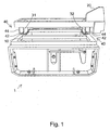
- an agricultural implement in the form of a yard scraper 1 comprises working portion comprising a frame 10, the frame coupled to a connection means 20.
- the connection means 20 is shown connected to an agricultural tractor.
- the yard scraper 1 can be pulled or pushed by a vehicle coupled to the connection means, and operates in a scraping direction left to right as seen in Figure 1 , and a reverse scraping direction right to left as seen in Figure 1 .
- the frame 10 and connection means 20 are coupled to one another by a flexible coupling means in the form of first and second coupling strips 31, 32.
- the first and second coupling strips 31, 32 are arranged substantially perpendicular to the scraping and reverse scraping directions.
- the coupling strips 31, 32 comprise a resilient, rubber material.
- Each coupling strip also has a stop means 40 associate therewith.
- connection means 20 is held by a vehicle so that the frame 10 depends from the connection means 20.
- the frame 10 comprises a base 12.
- the connection means 20 is held by a vehicle so that the base 12 is in contact with the surface to be scraped.
- first and second scraping blades are provided to engage the surface to be scraped and to perform the scraping.
- the first scraping blade is provided relatively further away from the tractor as shown in Figure 1
- the second scraping blade is provided relatively closer to the tractor as shown in Figure 1 .
- the first and second scraping blades are pivotally coupled to the frame 12, and can pivot towards one another.
- connection means 20 Any slight inaccuracy in the alignment of the connection means 20, or unevenness in the surface to be scraped are automatically compensated for by the natural flexibility and stretch of the coupling strips 31,32. Furthermore, excess scraping pressure can be avoided, as the coupling strips 31, 32 compress and buckle if the frame 10 is forced too close to the connection means 20. These factors combine allow a large tolerance in the positioning of the connection means 20 over which effective scraping can be achieved.
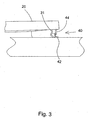
- the first coupling strip 31 has a stop means 40 adjacent to it, with the stop means 40 arranged to limit movement of the frame 10 relative to the connection means 20.
- the stop means 40 comprises a rigid flange 42 which is involved in limiting relative movement between the frame 10 and the connection means 20 parallel to the scraping direction, and further comprises a resilient flange 44 which is involved in limiting the approach of the connection means 20 to the frame 10, and also involved in limiting relative movement between the frame 10 and the connection means 20 parallel to the scraping direction.
- the rigid flange 42 extends from the frame 10 and runs alongside and parallel to the coupling strip 31. Displacement of the frame 10 in the reverse scraping direction relative to the connection means 20 causes the first coupling strip 31 to engage the rigid flange 42. Engagement of the first coupling strip 31 with the rigid flange is shown in Figure 2 .
- the resilient flange 44 extends from the connection means 20, and runs alongside and parallel to the coupling strip 31. Displacement of the frame 10 relative to the connection means 20 in the scraping direction causes the coupling strip to engage the rigid flange 42.
- the resilient flange 44 and the rigid flange 42 are located alongside the same side of the coupling strip 31 as one another.
- the resilient flange 44 can deform to allow some flexibility to the coupling between the frame 10 and the connection means 20 even when loading on the frame 10 causes relative displacement such that the rigid and resilient flanges 42, 44 contact one another.
- the resilient flange 44 may also engage the frame 20 to prevent vertical bumping of the frame 10 against the connection means 20.
- the second coupling strip 32 also has a stop means 40 adjacent to it, with the stop means 40 arranged to limit movement of the frame 10 relative to the connection means 20 in conjunction with the stop means 40 adjacent to the first coupling strip 31.
- the coupling strips 31, 32 and stop means 40 are generally symmetrical about a vertical reflection plane at the middle of the yard scraper 1 when viewed from the side.
- the operation of the stop means 40 located adjacent to the second coupling strip 32 will be not be described - it is clear that with the directions reversed the stop means both function in substantially the same way.
- Both first and second coupling strips 31, 32 and stop means 40 cooperate to maintain the relative position of the frame 10 and the coupling means 20 when the yard scraper 1 is in use.
- connection means 20 is arranged to be connected to a three-point linkage of an agricultural tractor.
- connection means 20 may have any suitable interface for coupling to a vehicle or other source of motive power.
- Coupling strips and resilient flanges of approximately 1-2cm thick rubber are preferred for yard scrapers of around 2m width.
- the material type and thickness chosen can be varied according to the weight, dimensions and expected scraping loads of a particular yard scraper.
- a range of plastics materials can be used.
- the second coupling strip 32 may be made thinner than the first coupling strip 31, or otherwise made more flexible. Typically, the loads imposed on the first coupling strip 31 in use are less than the loads imposed on the second coupling strip 32.
- Figures 4-7 show alternative coupling strips.
- a centrally positioned coupling strip 33 is provided, with stop means 40 as in the embodiment of Figures 1-3 .
- the centrally positioned coupling strip 33 is used with simplified stop means 40.
- the simplified stop means do not include the resilient flanges 44.
- Figure 6 shows an embodiment in which a central coupling strip 33 is provided; a simplified stop means 40 is provided for the second coupling strip, and the first coupling strip is at rest in a non-planar configuration, with upper and lower edges offset from one another.
- Figure 7 shows an embodiment in which first and second coupling strips 31, 32 are arranged at rest in a non-planar configuration, with upper and lower edges offset from one another.
- the coupling strips may be connected to the frame/connection means in such a way as to allow the position or rotation of the coupling strips to be adjusted. Such adjustment can be used to vary the load bearing characteristics of the coupling strips.
- the relative separation of the frame and connection means may also be altered this way, either by fixing in one of a plurality of predetermined settings or by powered on the fly adjustment.
- the coupling strips described exhibit desirable characteristics when the yard scraper is accelerated from rest, and when the yard scraper is in use scraping a surface. As the yard scraper is accelerated from rest the coupling strips are deflected, producing an upward force on the frame due to tension in the coupling strips. The upward force on the frame reduces the contact force with the surface to be scraped, and therefore reduces the frictional force between the frame and the surface to be scraped. Reducing the frictional force on acceleration reduces the demand on the vehicle drawing the yard scraper.
- the coupling strips are deformed by the weight and drag of the frame.
- the coupling strips can deform by twisting, buckling and compressing to absorb and/or deflect any accidental impacts between the frame 10 and e.g. a projecting wall or other obstacle.
- impact damage is restricted to the relatively inexpensive coupling strips, rather than to the metal components of the frame or connection means. This is so that repair of the yard scraper can be effected easily and cheaply.
- a yard scraper which is of simple construction, and which offers effective scraping without the need for complicated user adjustments.
- the yard scraper described also reduces blade wear, is effectively self levelling and has a benefits in resilience to cope with accidental knocks.
- other embodiments may comprise agricultural implements such as ploughs, balers, mowers etc.
Landscapes
- Life Sciences & Earth Sciences (AREA)
- Engineering & Computer Science (AREA)
- Mechanical Engineering (AREA)
- Environmental Sciences (AREA)
- Soil Sciences (AREA)
- General Engineering & Computer Science (AREA)
- Structural Engineering (AREA)
- Civil Engineering (AREA)
- Mining & Mineral Resources (AREA)
- Zoology (AREA)
- Agricultural Machines (AREA)
- Agricultural Chemicals And Associated Chemicals (AREA)
- Soil Working Implements (AREA)
- Transition And Organic Metals Composition Catalysts For Addition Polymerization (AREA)
- Management, Administration, Business Operations System, And Electronic Commerce (AREA)
- Catching Or Destruction (AREA)
Claims (7)
- Ein landwirtschaftliches Gerät (1) mit einem Arbeitsteil und einem Verbindungselement (20), das für eine Verbindung zu einem Fahrzeug angepasst ist. Das Arbeitsteil ist mittels einer biegsamen Kupplung (31, 32) an das Verbindungselement (20) angekuppelt;
Das biegsame Kupplungselement (31, 32) umfasst zwei Kupplungstreifen (31, 32);
Desweiteren umfasst das landwirtschaftliche Gerät einen Hofschaber (1). Das Arbeitsteil des Hofschabers besteht aus einem Rahmen (10) und einer ersten in Schaberichtung wirksamen Ziehklinge.
Der Rahmen (10) hängt an dem Verbindungselement (20), d.h. er wird durch die zwei Kupplungsstreifen (31, 32), die sich in Schaberichtung von einander trennen, abgestützt;
Dadurch gekennzeichnet, dass die zwei Kupplungsstreifen (31, 32) jeweils die Form eines Bandes < haben, wobei jedes Band in waagerechter Richtung ein Maß hat, das-> im Wesentlichen senkrecht zur Schaberichtung ist. - Das in Anspruch 1 beschriebene landwirtschaftliche Gerät, bei dem der Rahmen (10) eine zweite Ziehklinge umfasst, die in Schaberichtung von der ersten Ziehklinge abgetrennt ist. Jede Klinge kann sich in die Richtung der anderen drehen.
- Das in Anspruch 2 beschriebene landwirtschaftliche Gerät, bei dem die zweite Klinge in gegenläufiger Schaberichtung wirksam ist.
- Das in Anspruch 3 beschriebene landwirtschaftliche Gerät, bei dem die gegenläufige Schaberichtung parallel zur Schaberichtung, aber der ersten Schaberichtung entgegengesetzt ist.
- Das in Anspruch 2, 3 oder 4 beschriebene landwirtschaftliche Gerät, bei dem die erste und die zweite Klinge im Wesentlichen parallel zueinander sind.
- Das in einem der Ansprüche 1 bis 5 beschriebene landwirtschaftliche Gerät, bei dem eine oder beide Ziehklingen an der unteren Kante ein elastisches Teil hat bzw. haben.
- Das in Anspruch 6 beschriebene landwirtschaftliche Gerät, bei dem der elastische Teil aus einem Gummistreifen oder einem elastischen Kunststoffmaterial besteht.
Priority Applications (1)
| Application Number | Priority Date | Filing Date | Title |
|---|---|---|---|
| PL06808550T PL1973394T3 (pl) | 2005-12-01 | 2006-11-16 | Ulepszenia narzędzi rolniczych i ulepszenia związane z tymi narzędziami |
Applications Claiming Priority (2)
| Application Number | Priority Date | Filing Date | Title |
|---|---|---|---|
| GBGB0524476.9A GB0524476D0 (en) | 2005-12-01 | 2005-12-01 | Improvements in and relating to agricultural implements |
| PCT/GB2006/004260 WO2007063277A2 (en) | 2005-12-01 | 2006-11-16 | Improvements in and relating to agricultural implements |
Publications (2)
| Publication Number | Publication Date |
|---|---|
| EP1973394A2 EP1973394A2 (de) | 2008-10-01 |
| EP1973394B1 true EP1973394B1 (de) | 2010-07-28 |
Family
ID=35685840
Family Applications (1)
| Application Number | Title | Priority Date | Filing Date |
|---|---|---|---|
| EP06808550A Not-in-force EP1973394B1 (de) | 2005-12-01 | 2006-11-16 | Verbesserungen bei landwirtschaftlichen geräten und diese betreffende |
Country Status (7)
| Country | Link |
|---|---|
| US (1) | US20100294524A1 (de) |
| EP (1) | EP1973394B1 (de) |
| AT (1) | ATE475301T1 (de) |
| DE (1) | DE602006015858D1 (de) |
| GB (1) | GB0524476D0 (de) |
| PL (1) | PL1973394T3 (de) |
| WO (1) | WO2007063277A2 (de) |
Families Citing this family (1)
| Publication number | Priority date | Publication date | Assignee | Title |
|---|---|---|---|---|
| US10264721B2 (en) | 2017-01-10 | 2019-04-23 | Cnh Industrial America Llc | Agricultural implement with boltless tines |
Family Cites Families (23)
| Publication number | Priority date | Publication date | Assignee | Title |
|---|---|---|---|---|
| US1204245A (en) * | 1915-06-22 | 1916-11-07 | Edward George Carr | Concrete-tamper. |
| US2166596A (en) * | 1938-10-20 | 1939-07-18 | John C Johnson | Road drag |
| US2400321A (en) * | 1943-03-04 | 1946-05-14 | Kalman Floor Co | Concrete surfacing machine |
| US2760285A (en) * | 1953-03-13 | 1956-08-28 | F J Mccarthy Company | Road machinery |
| DE1534167B1 (de) * | 1965-12-22 | 1969-09-18 | Josef Meyer Eisenbau Ag | An Fahrzeugen anbaubare und hoehenverstellbare Vorrichtung zum Abschaben von auf Fahrbahnen befindlichen festgefahrenen Verunreinigungen bzw. Verkrustungen |
| DE2231023A1 (de) * | 1972-06-24 | 1974-01-10 | Bopparder Maschinenbau Gmbh | Vibrationsverdichter |
| US3889760A (en) * | 1973-07-11 | 1975-06-17 | Technion Res & Dev Foundation | Combined smoother and roller-packer |
| FR2419364A1 (fr) * | 1978-03-07 | 1979-10-05 | Farden Arne | Unite de travail compacte pour realiser l'excavation, le compactage et le chargement dans une operation de nivellement de route ou analogue |
| US4227581A (en) * | 1978-05-15 | 1980-10-14 | Klotzbach Harry A | Ground preparing apparatus for no-till planting |
| GB2050475B (en) * | 1979-05-03 | 1983-04-20 | Lawrenson J | Scraping apparatus |
| GB2192418A (en) * | 1986-07-09 | 1988-01-13 | Colin Golby Tustian | Screeding machine |
| DE8629208U1 (de) * | 1986-11-03 | 1987-01-02 | Bauer, Heinz-Dieter, 4286 Südlohn | Vorrichtung zur Halterung für ein Räumschild |
| US5255611A (en) * | 1988-10-13 | 1993-10-26 | Sig Schweizerische Industrie-Gesellschaft | Tilt compensator for high-speed vehicles, in particular rail vehicles |
| DE3937634C2 (de) * | 1989-11-11 | 1994-02-24 | Beilhack Maschf Martin | Schneepflug |
| GB9100665D0 (en) * | 1991-01-11 | 1991-02-27 | Massey Ferguson Services Nv | Implement control |
| GB9525688D0 (en) * | 1995-12-15 | 1996-02-14 | Thames Water Utilities | A dresser |
| JP3136264B2 (ja) * | 1996-02-15 | 2001-02-19 | ヤンマーディーゼル株式会社 | ロータリ耕耘装置 |
| SE507556C2 (sv) * | 1997-01-09 | 1998-06-22 | Goesta Kaellqvist | Hållare för plogskär |
| CA2287747A1 (en) * | 1999-10-29 | 2001-04-29 | Stephen Davies | Attachment for an all terrain vehicle |
| US6648078B1 (en) * | 2000-07-19 | 2003-11-18 | Moffett Marvin G | Apparatus for folding over corn stalk stubble and the like |
| CA2364224A1 (en) * | 2001-12-04 | 2003-06-04 | Andrew H. Johnson | Air spring force apparatus adapted for weight transfer |
| US7096971B1 (en) * | 2003-07-03 | 2006-08-29 | Gendron Robert J | Bi-directional drag grader |
| US7357597B2 (en) * | 2005-05-11 | 2008-04-15 | Laser Strike Llc | Concrete screed with movable leading edge |
-
2005
- 2005-12-01 GB GBGB0524476.9A patent/GB0524476D0/en not_active Ceased
-
2006
- 2006-11-16 DE DE602006015858T patent/DE602006015858D1/de active Active
- 2006-11-16 PL PL06808550T patent/PL1973394T3/pl unknown
- 2006-11-16 WO PCT/GB2006/004260 patent/WO2007063277A2/en not_active Ceased
- 2006-11-16 AT AT06808550T patent/ATE475301T1/de not_active IP Right Cessation
- 2006-11-16 US US12/095,624 patent/US20100294524A1/en not_active Abandoned
- 2006-11-16 EP EP06808550A patent/EP1973394B1/de not_active Not-in-force
Also Published As
| Publication number | Publication date |
|---|---|
| GB0524476D0 (en) | 2006-01-11 |
| EP1973394A2 (de) | 2008-10-01 |
| US20100294524A1 (en) | 2010-11-25 |
| WO2007063277A3 (en) | 2007-07-19 |
| DE602006015858D1 (de) | 2010-09-09 |
| ATE475301T1 (de) | 2010-08-15 |
| WO2007063277A2 (en) | 2007-06-07 |
| PL1973394T3 (pl) | 2011-01-31 |
Similar Documents
| Publication | Publication Date | Title |
|---|---|---|
| US7360327B2 (en) | Material moving pusher/bucket | |
| AU2019203750B2 (en) | Improvements to openers for seeders | |
| US5743032A (en) | Plough blade arrangement | |
| US20150135561A1 (en) | Skid device attachable to a bucket, bucket assembly for moving material, and method of forming the skid device | |
| KR102185802B1 (ko) | 흙 튀김 차단장치 | |
| US11326316B1 (en) | Snow plow cutting edge device and cutting edge attachments | |
| US20150299982A1 (en) | Fender Mounting System | |
| US20140054052A1 (en) | Support Apparatus For Securing A Wing Plow | |
| EP3524735A1 (de) | Verschleisspadanordnung für arbeitsgeräte von maschinen | |
| US20250089614A1 (en) | Mower system and connecting device thereof | |
| CN110080320A (zh) | 表面成形设备以及机动化表面成形设备 | |
| US4040261A (en) | Vibratory plow | |
| US20190257047A1 (en) | Snow plow assembly with floating a-frame | |
| CA3156874A1 (en) | Snow plow cutting edge device and cutting edge attachments | |
| EP1973394B1 (de) | Verbesserungen bei landwirtschaftlichen geräten und diese betreffende | |
| US5253717A (en) | Foldable agricultural implement | |
| KR101052197B1 (ko) | 트랙터 부착용 제설기 | |
| CN210562361U (zh) | 一种推土机构及铲土运输机械 | |
| US20050150668A1 (en) | Box scraper with scarifier | |
| KR102019871B1 (ko) | 트랙터용 써레 | |
| WO2019182582A1 (en) | Grading system | |
| US20150361638A1 (en) | Blade for a work vehicle | |
| AU732319C (en) | Ground working implement including a shank and a tip | |
| US10662593B1 (en) | Drag box apparatus | |
| US20040208737A1 (en) | Backhoe/loader bucket design, attachment, and method for converting existing buckets |
Legal Events
| Date | Code | Title | Description |
|---|---|---|---|
| PUAI | Public reference made under article 153(3) epc to a published international application that has entered the european phase |
Free format text: ORIGINAL CODE: 0009012 |
|
| 17P | Request for examination filed |
Effective date: 20080627 |
|
| AK | Designated contracting states |
Kind code of ref document: A2 Designated state(s): AT BE BG CH CY CZ DE DK EE ES FI FR GB GR HU IE IS IT LI LT LU LV MC NL PL PT RO SE SI SK TR |
|
| 17Q | First examination report despatched |
Effective date: 20081017 |
|
| GRAP | Despatch of communication of intention to grant a patent |
Free format text: ORIGINAL CODE: EPIDOSNIGR1 |
|
| DAX | Request for extension of the european patent (deleted) | ||
| GRAS | Grant fee paid |
Free format text: ORIGINAL CODE: EPIDOSNIGR3 |
|
| GRAA | (expected) grant |
Free format text: ORIGINAL CODE: 0009210 |
|
| AK | Designated contracting states |
Kind code of ref document: B1 Designated state(s): AT BE BG CH CY CZ DE DK EE ES FI FR GB GR HU IE IS IT LI LT LU LV MC NL PL PT RO SE SI SK TR |
|
| REG | Reference to a national code |
Ref country code: GB Ref legal event code: FG4D |
|
| REG | Reference to a national code |
Ref country code: CH Ref legal event code: EP |
|
| REG | Reference to a national code |
Ref country code: IE Ref legal event code: FG4D |
|
| REF | Corresponds to: |
Ref document number: 602006015858 Country of ref document: DE Date of ref document: 20100909 Kind code of ref document: P |
|
| REG | Reference to a national code |
Ref country code: NL Ref legal event code: VDEP Effective date: 20100728 |
|
| LTIE | Lt: invalidation of european patent or patent extension |
Effective date: 20100728 |
|
| PG25 | Lapsed in a contracting state [announced via postgrant information from national office to epo] |
Ref country code: NL Free format text: LAPSE BECAUSE OF FAILURE TO SUBMIT A TRANSLATION OF THE DESCRIPTION OR TO PAY THE FEE WITHIN THE PRESCRIBED TIME-LIMIT Effective date: 20100728 Ref country code: LT Free format text: LAPSE BECAUSE OF FAILURE TO SUBMIT A TRANSLATION OF THE DESCRIPTION OR TO PAY THE FEE WITHIN THE PRESCRIBED TIME-LIMIT Effective date: 20100728 Ref country code: FI Free format text: LAPSE BECAUSE OF FAILURE TO SUBMIT A TRANSLATION OF THE DESCRIPTION OR TO PAY THE FEE WITHIN THE PRESCRIBED TIME-LIMIT Effective date: 20100728 Ref country code: AT Free format text: LAPSE BECAUSE OF FAILURE TO SUBMIT A TRANSLATION OF THE DESCRIPTION OR TO PAY THE FEE WITHIN THE PRESCRIBED TIME-LIMIT Effective date: 20100728 |
|
| REG | Reference to a national code |
Ref country code: PL Ref legal event code: T3 |
|
| PG25 | Lapsed in a contracting state [announced via postgrant information from national office to epo] |
Ref country code: PT Free format text: LAPSE BECAUSE OF FAILURE TO SUBMIT A TRANSLATION OF THE DESCRIPTION OR TO PAY THE FEE WITHIN THE PRESCRIBED TIME-LIMIT Effective date: 20101129 Ref country code: SI Free format text: LAPSE BECAUSE OF FAILURE TO SUBMIT A TRANSLATION OF THE DESCRIPTION OR TO PAY THE FEE WITHIN THE PRESCRIBED TIME-LIMIT Effective date: 20100728 Ref country code: IS Free format text: LAPSE BECAUSE OF FAILURE TO SUBMIT A TRANSLATION OF THE DESCRIPTION OR TO PAY THE FEE WITHIN THE PRESCRIBED TIME-LIMIT Effective date: 20101128 Ref country code: BG Free format text: LAPSE BECAUSE OF FAILURE TO SUBMIT A TRANSLATION OF THE DESCRIPTION OR TO PAY THE FEE WITHIN THE PRESCRIBED TIME-LIMIT Effective date: 20101028 Ref country code: CY Free format text: LAPSE BECAUSE OF FAILURE TO SUBMIT A TRANSLATION OF THE DESCRIPTION OR TO PAY THE FEE WITHIN THE PRESCRIBED TIME-LIMIT Effective date: 20100728 |
|
| PG25 | Lapsed in a contracting state [announced via postgrant information from national office to epo] |
Ref country code: BE Free format text: LAPSE BECAUSE OF FAILURE TO SUBMIT A TRANSLATION OF THE DESCRIPTION OR TO PAY THE FEE WITHIN THE PRESCRIBED TIME-LIMIT Effective date: 20100728 Ref country code: SE Free format text: LAPSE BECAUSE OF FAILURE TO SUBMIT A TRANSLATION OF THE DESCRIPTION OR TO PAY THE FEE WITHIN THE PRESCRIBED TIME-LIMIT Effective date: 20100728 Ref country code: LV Free format text: LAPSE BECAUSE OF FAILURE TO SUBMIT A TRANSLATION OF THE DESCRIPTION OR TO PAY THE FEE WITHIN THE PRESCRIBED TIME-LIMIT Effective date: 20100728 Ref country code: GR Free format text: LAPSE BECAUSE OF FAILURE TO SUBMIT A TRANSLATION OF THE DESCRIPTION OR TO PAY THE FEE WITHIN THE PRESCRIBED TIME-LIMIT Effective date: 20101029 |
|
| PG25 | Lapsed in a contracting state [announced via postgrant information from national office to epo] |
Ref country code: DK Free format text: LAPSE BECAUSE OF FAILURE TO SUBMIT A TRANSLATION OF THE DESCRIPTION OR TO PAY THE FEE WITHIN THE PRESCRIBED TIME-LIMIT Effective date: 20100728 |
|
| PG25 | Lapsed in a contracting state [announced via postgrant information from national office to epo] |
Ref country code: CZ Free format text: LAPSE BECAUSE OF FAILURE TO SUBMIT A TRANSLATION OF THE DESCRIPTION OR TO PAY THE FEE WITHIN THE PRESCRIBED TIME-LIMIT Effective date: 20100728 Ref country code: SK Free format text: LAPSE BECAUSE OF FAILURE TO SUBMIT A TRANSLATION OF THE DESCRIPTION OR TO PAY THE FEE WITHIN THE PRESCRIBED TIME-LIMIT Effective date: 20100728 Ref country code: IT Free format text: LAPSE BECAUSE OF FAILURE TO SUBMIT A TRANSLATION OF THE DESCRIPTION OR TO PAY THE FEE WITHIN THE PRESCRIBED TIME-LIMIT Effective date: 20100728 Ref country code: EE Free format text: LAPSE BECAUSE OF FAILURE TO SUBMIT A TRANSLATION OF THE DESCRIPTION OR TO PAY THE FEE WITHIN THE PRESCRIBED TIME-LIMIT Effective date: 20100728 Ref country code: RO Free format text: LAPSE BECAUSE OF FAILURE TO SUBMIT A TRANSLATION OF THE DESCRIPTION OR TO PAY THE FEE WITHIN THE PRESCRIBED TIME-LIMIT Effective date: 20100728 |
|
| PLBE | No opposition filed within time limit |
Free format text: ORIGINAL CODE: 0009261 |
|
| STAA | Information on the status of an ep patent application or granted ep patent |
Free format text: STATUS: NO OPPOSITION FILED WITHIN TIME LIMIT |
|
| PG25 | Lapsed in a contracting state [announced via postgrant information from national office to epo] |
Ref country code: MC Free format text: LAPSE BECAUSE OF NON-PAYMENT OF DUE FEES Effective date: 20101130 Ref country code: ES Free format text: LAPSE BECAUSE OF FAILURE TO SUBMIT A TRANSLATION OF THE DESCRIPTION OR TO PAY THE FEE WITHIN THE PRESCRIBED TIME-LIMIT Effective date: 20101108 |
|
| REG | Reference to a national code |
Ref country code: CH Ref legal event code: PL |
|
| 26N | No opposition filed |
Effective date: 20110429 |
|
| PG25 | Lapsed in a contracting state [announced via postgrant information from national office to epo] |
Ref country code: CH Free format text: LAPSE BECAUSE OF NON-PAYMENT OF DUE FEES Effective date: 20101130 Ref country code: LI Free format text: LAPSE BECAUSE OF NON-PAYMENT OF DUE FEES Effective date: 20101130 |
|
| REG | Reference to a national code |
Ref country code: DE Ref legal event code: R097 Ref document number: 602006015858 Country of ref document: DE Effective date: 20110429 |
|
| PG25 | Lapsed in a contracting state [announced via postgrant information from national office to epo] |
Ref country code: HU Free format text: LAPSE BECAUSE OF FAILURE TO SUBMIT A TRANSLATION OF THE DESCRIPTION OR TO PAY THE FEE WITHIN THE PRESCRIBED TIME-LIMIT Effective date: 20110129 Ref country code: LU Free format text: LAPSE BECAUSE OF NON-PAYMENT OF DUE FEES Effective date: 20101116 |
|
| PG25 | Lapsed in a contracting state [announced via postgrant information from national office to epo] |
Ref country code: TR Free format text: LAPSE BECAUSE OF FAILURE TO SUBMIT A TRANSLATION OF THE DESCRIPTION OR TO PAY THE FEE WITHIN THE PRESCRIBED TIME-LIMIT Effective date: 20100728 |
|
| PGFP | Annual fee paid to national office [announced via postgrant information from national office to epo] |
Ref country code: IE Payment date: 20140530 Year of fee payment: 8 Ref country code: GB Payment date: 20140530 Year of fee payment: 8 |
|
| REG | Reference to a national code |
Ref country code: FR Ref legal event code: ST Effective date: 20140731 |
|
| PGFP | Annual fee paid to national office [announced via postgrant information from national office to epo] |
Ref country code: DE Payment date: 20140530 Year of fee payment: 8 |
|
| REG | Reference to a national code |
Ref country code: FR Ref legal event code: D3 Effective date: 20140916 |
|
| PGFP | Annual fee paid to national office [announced via postgrant information from national office to epo] |
Ref country code: FR Payment date: 20140530 Year of fee payment: 8 |
|
| PGRI | Patent reinstated in contracting state [announced from national office to epo] |
Ref country code: FR Effective date: 20140916 |
|
| REG | Reference to a national code |
Ref country code: DE Ref legal event code: R119 Ref document number: 602006015858 Country of ref document: DE |
|
| GBPC | Gb: european patent ceased through non-payment of renewal fee |
Effective date: 20141116 |
|
| REG | Reference to a national code |
Ref country code: IE Ref legal event code: MM4A |
|
| REG | Reference to a national code |
Ref country code: FR Ref legal event code: ST Effective date: 20150731 |
|
| PGFP | Annual fee paid to national office [announced via postgrant information from national office to epo] |
Ref country code: PL Payment date: 20150515 Year of fee payment: 9 |
|
| PG25 | Lapsed in a contracting state [announced via postgrant information from national office to epo] |
Ref country code: IE Free format text: LAPSE BECAUSE OF NON-PAYMENT OF DUE FEES Effective date: 20141116 Ref country code: DE Free format text: LAPSE BECAUSE OF NON-PAYMENT OF DUE FEES Effective date: 20150602 Ref country code: GB Free format text: LAPSE BECAUSE OF NON-PAYMENT OF DUE FEES Effective date: 20141116 |
|
| PG25 | Lapsed in a contracting state [announced via postgrant information from national office to epo] |
Ref country code: FR Free format text: LAPSE BECAUSE OF NON-PAYMENT OF DUE FEES Effective date: 20141201 |
|
| PG25 | Lapsed in a contracting state [announced via postgrant information from national office to epo] |
Ref country code: PL Free format text: LAPSE BECAUSE OF NON-PAYMENT OF DUE FEES Effective date: 20151116 |