EP3439971B1 - Method and apparatus for forming pack bodies which are open on one side from pack sleeves which are open on both sides - Google Patents
Method and apparatus for forming pack bodies which are open on one side from pack sleeves which are open on both sides Download PDFInfo
- Publication number
- EP3439971B1 EP3439971B1 EP17716150.2A EP17716150A EP3439971B1 EP 3439971 B1 EP3439971 B1 EP 3439971B1 EP 17716150 A EP17716150 A EP 17716150A EP 3439971 B1 EP3439971 B1 EP 3439971B1
- Authority
- EP
- European Patent Office
- Prior art keywords
- package
- sleeve
- sleeves
- mandrel
- jacket
- Prior art date
- Legal status (The legal status is an assumption and is not a legal conclusion. Google has not performed a legal analysis and makes no representation as to the accuracy of the status listed.)
- Active
Links
- 238000000034 method Methods 0.000 title claims description 27
- 238000003825 pressing Methods 0.000 claims description 28
- 238000007789 sealing Methods 0.000 claims description 26
- 238000000465 moulding Methods 0.000 claims description 20
- 238000012546 transfer Methods 0.000 claims description 12
- 238000004519 manufacturing process Methods 0.000 claims description 11
- 239000000463 material Substances 0.000 claims description 8
- 238000012545 processing Methods 0.000 claims description 6
- 230000015572 biosynthetic process Effects 0.000 claims description 5
- 230000002829 reductive effect Effects 0.000 claims description 4
- 238000012856 packing Methods 0.000 description 223
- 238000004806 packaging method and process Methods 0.000 description 158
- 239000005022 packaging material Substances 0.000 description 30
- 210000005069 ears Anatomy 0.000 description 26
- 238000007493 shaping process Methods 0.000 description 11
- 230000036961 partial effect Effects 0.000 description 7
- 230000001954 sterilising effect Effects 0.000 description 7
- 235000013305 food Nutrition 0.000 description 6
- 238000004659 sterilization and disinfection Methods 0.000 description 6
- MHAJPDPJQMAIIY-UHFFFAOYSA-N Hydrogen peroxide Chemical compound OO MHAJPDPJQMAIIY-UHFFFAOYSA-N 0.000 description 4
- 239000004698 Polyethylene Substances 0.000 description 4
- 239000002131 composite material Substances 0.000 description 4
- 229920000573 polyethylene Polymers 0.000 description 4
- 230000003313 weakening effect Effects 0.000 description 4
- 239000004033 plastic Substances 0.000 description 3
- 229920003023 plastic Polymers 0.000 description 3
- XAGFODPZIPBFFR-UHFFFAOYSA-N aluminium Chemical compound [Al] XAGFODPZIPBFFR-UHFFFAOYSA-N 0.000 description 2
- 229910052782 aluminium Inorganic materials 0.000 description 2
- 230000007423 decrease Effects 0.000 description 2
- 238000006073 displacement reaction Methods 0.000 description 2
- 230000002349 favourable effect Effects 0.000 description 2
- -1 polyethylene Polymers 0.000 description 2
- 238000004080 punching Methods 0.000 description 2
- 229920001169 thermoplastic Polymers 0.000 description 2
- 239000004416 thermosoftening plastic Substances 0.000 description 2
- 229920000219 Ethylene vinyl alcohol Polymers 0.000 description 1
- 239000004952 Polyamide Substances 0.000 description 1
- 238000010521 absorption reaction Methods 0.000 description 1
- 230000009471 action Effects 0.000 description 1
- 238000004026 adhesive bonding Methods 0.000 description 1
- 238000013459 approach Methods 0.000 description 1
- QVGXLLKOCUKJST-UHFFFAOYSA-N atomic oxygen Chemical compound [O] QVGXLLKOCUKJST-UHFFFAOYSA-N 0.000 description 1
- 230000004888 barrier function Effects 0.000 description 1
- 238000005452 bending Methods 0.000 description 1
- 230000008901 benefit Effects 0.000 description 1
- 235000013361 beverage Nutrition 0.000 description 1
- 238000007664 blowing Methods 0.000 description 1
- 230000008859 change Effects 0.000 description 1
- 238000005352 clarification Methods 0.000 description 1
- 238000009792 diffusion process Methods 0.000 description 1
- 238000001035 drying Methods 0.000 description 1
- 239000004715 ethylene vinyl alcohol Substances 0.000 description 1
- 230000009969 flowable effect Effects 0.000 description 1
- 239000007789 gas Substances 0.000 description 1
- 238000010438 heat treatment Methods 0.000 description 1
- RZXDTJIXPSCHCI-UHFFFAOYSA-N hexa-1,5-diene-2,5-diol Chemical compound OC(=C)CCC(O)=C RZXDTJIXPSCHCI-UHFFFAOYSA-N 0.000 description 1
- 230000001771 impaired effect Effects 0.000 description 1
- 230000003287 optical effect Effects 0.000 description 1
- 239000001301 oxygen Substances 0.000 description 1
- 229910052760 oxygen Inorganic materials 0.000 description 1
- 230000000149 penetrating effect Effects 0.000 description 1
- 229920002647 polyamide Polymers 0.000 description 1
- 230000008569 process Effects 0.000 description 1
- 230000009467 reduction Effects 0.000 description 1
- 230000000717 retained effect Effects 0.000 description 1
- 230000003068 static effect Effects 0.000 description 1
- 238000003860 storage Methods 0.000 description 1
- 239000000126 substance Substances 0.000 description 1
- 230000007704 transition Effects 0.000 description 1
Images


Classifications
-
- B—PERFORMING OPERATIONS; TRANSPORTING
- B65—CONVEYING; PACKING; STORING; HANDLING THIN OR FILAMENTARY MATERIAL
- B65B—MACHINES, APPARATUS OR DEVICES FOR, OR METHODS OF, PACKAGING ARTICLES OR MATERIALS; UNPACKING
- B65B3/00—Packaging plastic material, semiliquids, liquids or mixed solids and liquids, in individual containers or receptacles, e.g. bags, sacks, boxes, cartons, cans, or jars
- B65B3/02—Machines characterised by the incorporation of means for making the containers or receptacles
- B65B3/025—Making parallelepipedal containers from a single carton blank
-
- B—PERFORMING OPERATIONS; TRANSPORTING
- B31—MAKING ARTICLES OF PAPER, CARDBOARD OR MATERIAL WORKED IN A MANNER ANALOGOUS TO PAPER; WORKING PAPER, CARDBOARD OR MATERIAL WORKED IN A MANNER ANALOGOUS TO PAPER
- B31B—MAKING CONTAINERS OF PAPER, CARDBOARD OR MATERIAL WORKED IN A MANNER ANALOGOUS TO PAPER
- B31B50/00—Making rigid or semi-rigid containers, e.g. boxes or cartons
- B31B50/006—Controlling; Regulating; Measuring; Improving safety
-
- B—PERFORMING OPERATIONS; TRANSPORTING
- B31—MAKING ARTICLES OF PAPER, CARDBOARD OR MATERIAL WORKED IN A MANNER ANALOGOUS TO PAPER; WORKING PAPER, CARDBOARD OR MATERIAL WORKED IN A MANNER ANALOGOUS TO PAPER
- B31B—MAKING CONTAINERS OF PAPER, CARDBOARD OR MATERIAL WORKED IN A MANNER ANALOGOUS TO PAPER
- B31B50/00—Making rigid or semi-rigid containers, e.g. boxes or cartons
- B31B50/26—Folding sheets, blanks or webs
- B31B50/28—Folding sheets, blanks or webs around mandrels, e.g. for forming bottoms
- B31B50/30—Folding sheets, blanks or webs around mandrels, e.g. for forming bottoms the mandrels moving
- B31B50/32—Folding sheets, blanks or webs around mandrels, e.g. for forming bottoms the mandrels moving in circular paths
- B31B50/322—Folding sheets, blanks or webs around mandrels, e.g. for forming bottoms the mandrels moving in circular paths the mandrels extending radially from the periphery of a drum
-
- B—PERFORMING OPERATIONS; TRANSPORTING
- B31—MAKING ARTICLES OF PAPER, CARDBOARD OR MATERIAL WORKED IN A MANNER ANALOGOUS TO PAPER; WORKING PAPER, CARDBOARD OR MATERIAL WORKED IN A MANNER ANALOGOUS TO PAPER
- B31B—MAKING CONTAINERS OF PAPER, CARDBOARD OR MATERIAL WORKED IN A MANNER ANALOGOUS TO PAPER
- B31B50/00—Making rigid or semi-rigid containers, e.g. boxes or cartons
- B31B50/74—Auxiliary operations
- B31B50/76—Opening and distending flattened articles
- B31B50/78—Mechanically
- B31B50/782—Mechanically by pushing the opposite ends of collapsed blanks towards each other
-
- B—PERFORMING OPERATIONS; TRANSPORTING
- B31—MAKING ARTICLES OF PAPER, CARDBOARD OR MATERIAL WORKED IN A MANNER ANALOGOUS TO PAPER; WORKING PAPER, CARDBOARD OR MATERIAL WORKED IN A MANNER ANALOGOUS TO PAPER
- B31B—MAKING CONTAINERS OF PAPER, CARDBOARD OR MATERIAL WORKED IN A MANNER ANALOGOUS TO PAPER
- B31B50/00—Making rigid or semi-rigid containers, e.g. boxes or cartons
- B31B50/74—Auxiliary operations
- B31B50/76—Opening and distending flattened articles
- B31B50/78—Mechanically
- B31B50/788—Mechanically by introducing the blanks into undeformable holders, e.g. on a drum or on chains
-
- B—PERFORMING OPERATIONS; TRANSPORTING
- B65—CONVEYING; PACKING; STORING; HANDLING THIN OR FILAMENTARY MATERIAL
- B65B—MACHINES, APPARATUS OR DEVICES FOR, OR METHODS OF, PACKAGING ARTICLES OR MATERIALS; UNPACKING
- B65B41/00—Supplying or feeding container-forming sheets or wrapping material
- B65B41/02—Feeding sheets or wrapper blanks
- B65B41/04—Feeding sheets or wrapper blanks by grippers
- B65B41/06—Feeding sheets or wrapper blanks by grippers by suction-operated grippers
-
- B—PERFORMING OPERATIONS; TRANSPORTING
- B65—CONVEYING; PACKING; STORING; HANDLING THIN OR FILAMENTARY MATERIAL
- B65B—MACHINES, APPARATUS OR DEVICES FOR, OR METHODS OF, PACKAGING ARTICLES OR MATERIALS; UNPACKING
- B65B43/00—Forming, feeding, opening or setting-up containers or receptacles in association with packaging
- B65B43/12—Feeding flexible bags or carton blanks in flat or collapsed state; Feeding flat bags connected to form a series or chain
- B65B43/14—Feeding individual bags or carton blanks from piles or magazines
- B65B43/145—Feeding carton blanks from piles or magazines
-
- B—PERFORMING OPERATIONS; TRANSPORTING
- B65—CONVEYING; PACKING; STORING; HANDLING THIN OR FILAMENTARY MATERIAL
- B65B—MACHINES, APPARATUS OR DEVICES FOR, OR METHODS OF, PACKAGING ARTICLES OR MATERIALS; UNPACKING
- B65B43/00—Forming, feeding, opening or setting-up containers or receptacles in association with packaging
- B65B43/26—Opening or distending bags; Opening, erecting, or setting-up boxes, cartons, or carton blanks
- B65B43/32—Opening or distending bags; Opening, erecting, or setting-up boxes, cartons, or carton blanks by external pressure diagonally applied
- B65B43/325—Opening or distending bags; Opening, erecting, or setting-up boxes, cartons, or carton blanks by external pressure diagonally applied to boxes, cartons or carton blanks
-
- B—PERFORMING OPERATIONS; TRANSPORTING
- B65—CONVEYING; PACKING; STORING; HANDLING THIN OR FILAMENTARY MATERIAL
- B65B—MACHINES, APPARATUS OR DEVICES FOR, OR METHODS OF, PACKAGING ARTICLES OR MATERIALS; UNPACKING
- B65B43/00—Forming, feeding, opening or setting-up containers or receptacles in association with packaging
- B65B43/42—Feeding or positioning bags, boxes, or cartons in the distended, opened, or set-up state; Feeding preformed rigid containers, e.g. tins, capsules, glass tubes, glasses, to the packaging position; Locating containers or receptacles at the filling position; Supporting containers or receptacles during the filling operation
- B65B43/50—Feeding or positioning bags, boxes, or cartons in the distended, opened, or set-up state; Feeding preformed rigid containers, e.g. tins, capsules, glass tubes, glasses, to the packaging position; Locating containers or receptacles at the filling position; Supporting containers or receptacles during the filling operation using rotary tables or turrets
-
- B—PERFORMING OPERATIONS; TRANSPORTING
- B65—CONVEYING; PACKING; STORING; HANDLING THIN OR FILAMENTARY MATERIAL
- B65B—MACHINES, APPARATUS OR DEVICES FOR, OR METHODS OF, PACKAGING ARTICLES OR MATERIALS; UNPACKING
- B65B43/00—Forming, feeding, opening or setting-up containers or receptacles in association with packaging
- B65B43/42—Feeding or positioning bags, boxes, or cartons in the distended, opened, or set-up state; Feeding preformed rigid containers, e.g. tins, capsules, glass tubes, glasses, to the packaging position; Locating containers or receptacles at the filling position; Supporting containers or receptacles during the filling operation
- B65B43/54—Means for supporting containers or receptacles during the filling operation
-
- B—PERFORMING OPERATIONS; TRANSPORTING
- B65—CONVEYING; PACKING; STORING; HANDLING THIN OR FILAMENTARY MATERIAL
- B65B—MACHINES, APPARATUS OR DEVICES FOR, OR METHODS OF, PACKAGING ARTICLES OR MATERIALS; UNPACKING
- B65B55/00—Preserving, protecting or purifying packages or package contents in association with packaging
- B65B55/02—Sterilising, e.g. of complete packages
- B65B55/04—Sterilising wrappers or receptacles prior to, or during, packaging
- B65B55/10—Sterilising wrappers or receptacles prior to, or during, packaging by liquids or gases
-
- B—PERFORMING OPERATIONS; TRANSPORTING
- B65—CONVEYING; PACKING; STORING; HANDLING THIN OR FILAMENTARY MATERIAL
- B65B—MACHINES, APPARATUS OR DEVICES FOR, OR METHODS OF, PACKAGING ARTICLES OR MATERIALS; UNPACKING
- B65B61/00—Auxiliary devices, not otherwise provided for, for operating on sheets, blanks, webs, binding material, containers or packages
- B65B61/24—Auxiliary devices, not otherwise provided for, for operating on sheets, blanks, webs, binding material, containers or packages for shaping or reshaping completed packages
-
- B—PERFORMING OPERATIONS; TRANSPORTING
- B65—CONVEYING; PACKING; STORING; HANDLING THIN OR FILAMENTARY MATERIAL
- B65B—MACHINES, APPARATUS OR DEVICES FOR, OR METHODS OF, PACKAGING ARTICLES OR MATERIALS; UNPACKING
- B65B7/00—Closing containers or receptacles after filling
- B65B7/16—Closing semi-rigid or rigid containers or receptacles not deformed by, or not taking-up shape of, contents, e.g. boxes or cartons
-
- B—PERFORMING OPERATIONS; TRANSPORTING
- B31—MAKING ARTICLES OF PAPER, CARDBOARD OR MATERIAL WORKED IN A MANNER ANALOGOUS TO PAPER; WORKING PAPER, CARDBOARD OR MATERIAL WORKED IN A MANNER ANALOGOUS TO PAPER
- B31B—MAKING CONTAINERS OF PAPER, CARDBOARD OR MATERIAL WORKED IN A MANNER ANALOGOUS TO PAPER
- B31B2100/00—Rigid or semi-rigid containers made by folding single-piece sheets, blanks or webs
- B31B2100/002—Rigid or semi-rigid containers made by folding single-piece sheets, blanks or webs characterised by the shape of the blank from which they are formed
- B31B2100/0022—Rigid or semi-rigid containers made by folding single-piece sheets, blanks or webs characterised by the shape of the blank from which they are formed made from tubular webs or blanks, including by tube or bottom forming operations
-
- B—PERFORMING OPERATIONS; TRANSPORTING
- B31—MAKING ARTICLES OF PAPER, CARDBOARD OR MATERIAL WORKED IN A MANNER ANALOGOUS TO PAPER; WORKING PAPER, CARDBOARD OR MATERIAL WORKED IN A MANNER ANALOGOUS TO PAPER
- B31B—MAKING CONTAINERS OF PAPER, CARDBOARD OR MATERIAL WORKED IN A MANNER ANALOGOUS TO PAPER
- B31B2105/00—Rigid or semi-rigid containers made by assembling separate sheets, blanks or webs
- B31B2105/002—Making boxes characterised by the shape of the blanks from which they are formed
- B31B2105/0022—Making boxes from tubular webs or blanks, e.g. with separate bottoms, including tube or bottom forming operations
Definitions
- the invention relates to a method for forming packaging bodies which are open on one side from packaging casings which are open on both sides for the production of filled packs.
- the invention further relates to a device for forming packaging bodies which are open on one side from packaging casings which are open on both sides for the production of filled packs according to the preamble of claim 10.
- Methods and devices for forming packaging bodies that are open on one side from packaging casings that are open on both sides have been known for some time.
- the methods are used, in particular, to produce filled packs, and processes and devices for filling packs with products in different configurations are also known.
- package bodies are understood to mean containers such as, for example, composite cardboard packaging, which are at least partially formed from a packaging material in the form of a laminate comprising a cardboard layer and outer, in particular thermoplastic, plastic layers, for example of polyethylene (PE).
- the carton gives the packs sufficient stability so that the packs can be handled easily and, for example, stacked.
- the plastic layers protect the cardboard from moisture and the food from the absorption of unwanted substances from the pack.
- Corresponding packing bodies are typically filled with products in the form of foodstuffs, in particular beverages, the flow products being predominantly products.
- the packing bodies are filled with food in a sterile or aseptic environment of a filling machine, since the food should be kept for a long time after the packs have been filled.
- the filling machines have, for example, sterilization rooms or aseptic chambers in which the packing bodies are sterilized and then filled and sealed under as sterile conditions as possible. After the packing bodies have been filled, they are typically sealed in the filling machine. When using appropriate packaging materials, the package body is closed by sealing the open end.
- the packing bodies are preferably formed on the filling machine from packing sleeves, which in turn are made from packaging blanks, in particular by sealing the longitudinal edges of the packaging blanks to one another.
- the inner longitudinal edge can be folded outwards in order to prevent moisture from penetrating into the packaging material, in particular the carton.
- packaging shells are made from a packaging material that are open at the opposite longitudinal ends.
- the pack sleeves are pre-folded along four fold lines running longitudinally to the pack sleeve, creating fold edges which form the later edges of the pack, which typically forms a square or rectangular cross section. First, however, the packaging sleeves are folded flat around two opposite folding edges. Two of the pre-folded fold lines are folded back.
- the packing jacket then essentially forms two sections running parallel to one another and lying one on top of the other.
- the flat-folded packaging sleeves are transferred as a stack to a magazine on the filling machine.
- the front section of the packaging jacket at the front end of the stack is gripped by suction cups and away from the stack pulled, the packing jacket unfolding, typically until an at least substantially square or rectangular cross section is formed.
- the unfolding takes place along the pre-folded folding lines, two of which have formed the folding edges of the folded-up packaging jacket, since the packaging material can be easily folded or folded along the, in particular pre-folded, folding lines.
- the correspondingly unfolded packing jacket is then pulled onto a mandrel of a so-called mandrel wheel, the cross section of the mandrel corresponding to the cross section of the packing jacket.
- the packing jacket protrudes outward beyond the mandrel so that the protruding part of the packing jacket can be folded against the end face of the mandrel and pressed and sealed there.
- the corresponding longitudinal end of the packaging jacket is closed and regularly forms the bottom of the later filled package. Alternatively, the closed end of the package jacket could also form the head of the later package if it is filled through the open bottom, for example.
- the packaging bodies which are open on one side, are introduced into a sterilization zone of the filling machine. This is usually done by successively transferring the package bodies to the cells of a transport device that receive the package bodies. The transport device then ensures that the package bodies are transported through the sterilization zone of the filling machine at a defined speed and at a defined distance from one another. In the sterilization zone, the package bodies are preheated with hot sterile air and then sterilized, typically with hydrogen peroxide, and dried with sterile air. The sterile packing bodies are transferred to the filling and sealing zone and filled there. The opening of the filled packing bodies is then closed before the closed packing is transported out of the filling and sealing zone via the transport device and is then removed from the corresponding cells of the transport device.
- the packing bodies are transported by the transport device in a straight line through the filling machine.
- Corresponding filling machines are also called cross-country skiers.
- the so-called rotary machines the packing bodies describe a more or less arc-shaped movement, which can comprise one or more circular arc sections.
- the present invention basically relates to both types of filling machines.
- the method and the device of the type described above have proven themselves for the production of packs with at least substantially rectangular or square cross sections. However, the production of packs with cross sections that differ significantly therefrom is only possible to a limited extent or not at all.
- the packing sleeves have to be folded flat for reasons of space and then simply and reliably formed using the mandrel wheel.
- the shape of the packs must allow the pack sleeves to easily reach the mandrel wheel and the pack bodies to be reliably removed from the mandrel wheel.
- the present invention is therefore based on the object of designing and developing the method and the device of the type mentioned at the outset in such a way that packs with a cross section which is neither square nor rectangular can be formed simply and reliably.
- This object is achieved according to claim 1 by a method for forming packaging bodies which are open on one side from packaging casings which are open on both sides for the production of filled packings in that the packaging casings in the forming station come into contact with one another with the two opposite folded edges of the packaging casing and are transverse to it Packing jacket tapered channel are pulled, the packing sleeves at the end of the channel engage in grooves associated with opposite sides of the channel.
- the above object is also achieved in a device according to the preamble of claim 10 in that the forming station has a channel for partially unfolding the packing sleeves moved through the channel and that opposite grooves are provided at the end of the channel for receiving the folded edges of the packing sleeves.
- the use of the forming station allows the use of packing sleeves with only two folding edges, if necessary, which serve to fold the packing sleeves flat to accommodate them in a stack.
- the two folded edges do not have to determine the shape, in particular the cross section, of the later pack.
- the pack sleeves can be brought into the desired shape without the folded edges having to be arranged in corners of the pack or on edges of the jacket of the pack.
- the folded edges can be arranged, for example, in flat sections of the casing of the pack, around the edges of the casing of the pack, regardless of the position of the folded edges to be able to provide or to avoid sharp edges partially or completely if necessary.
- the edge regions of the shells of the packs can thus be formed with a very large radius in the forming station, and curved side walls of the sheath of the pack can also be formed more easily, alternatively or additionally.
- the packaging jacket preferably has further fold lines or creasing lines, which serve, for example, to fold the longitudinal ends of the packaging jacket for the purpose of closing the packaging jacket.
- a head and a bottom of the pack are preferably formed by folding along the further fold lines, and are sealed in particular.
- the fold lines or crease lines are preferably stamped into the packaging material, in particular by so-called creasing, which is why the fold lines produced in this way can also be referred to as crease lines.
- the fold lines or crease lines are created by means of a line-shaped material displacement with tools that press against the packaging material, for example with punching or pressing tools.
- the fold lines or crease lines form line-like material weakenings of the packaging material. The bendability of the packaging material is increased along the fold lines thus produced.
- folding lines and / or folding edges of the finished package can cause folds or kinks in the packaging material, by reducing the number of folding lines and / or folding edges, wider areas of the package can be created without undesired kinks or folds, which may be preferred.
- the packs can, for example, be uniformly curved, rounded and / or curved in these areas without this shape being impaired by kinks or folds.
- the at least two fold lines or crease lines which serve for the flat folding of the packaging jacket and accordingly form the at least two folding edges of the packaging jacket, are preferably so-called “false folding lines” which later do not form an edge of the packaging or packaging. Folding along the false fold lines therefore only takes place to form the packaging jacket, but not in the packaging produced therefrom, which together with the filling can form the packaging.
- These false fold lines - like conventional fold lines - should make it easier to fold the packaging jacket.
- These fold lines are referred to as "false fold lines” because they are only used when the packaging jacket is folded flat, but when it is unfolded to produce the package body or those to be filled Packaging should be folded at least approximately straight again.
- Creases are linear material displacements that are stamped or rolled into the composite material using punching or pressing tools.
- the two false fold lines are straight and run parallel to each other.
- the packaging jacket is folded along the at least two false fold lines, which thus form the folded edges.
- fold lines can also be provided.
- these are those which do not extend or only extend in a straight line over part of the longitudinal extent of the packaging jacket. These can form correspondingly shaped edges which, for example, make it easier to hold and grip the later pack. This also results in increased flexibility in the choice of the shape of the pack, without having to adhere to the known four preformed folding lines for unfolding the pack jacket.
- the transfer device can for example be designed as a gripping arm or comprise a gripping arm.
- the transfer device can comprise at least one finger which can engage a packaging jacket and thus shift the packaging jacket.
- Other known transfer devices are also conceivable.
- the push-on device can also comprise at least one finger for gripping the packing edge and pushing the packing casing onto the mandrel.
- the packing jacket can also be transferred directly from a mold to the mandrel to unfold the packing jacket, so that the push-on device can be designed to move the mold appropriately over the mandrel.
- other known slide-on devices are also conceivable.
- the packaging sleeves are folded flat by exactly two folded edges. This allows space-saving storage of the packaging sleeves in a stack.
- the packaging sleeves then only have to be folded over two folded edges.
- the two fold lines for forming the fold edges are preferably "false fold lines" of the type described, which therefore do not later form an edge of the packaging or pack. Folding along the false fold lines therefore only takes place in the case of the packaging, but not in the packaging or packaging produced therefrom.
- fold lines can also be provided in this case.
- these are again those which do not extend or only extend in a straight line over part of the longitudinal extent of the packaging jacket.
- These can form correspondingly shaped edges which, for example, make it easier to hold and grip the later pack. This also results in increased flexibility in the choice of the shape of the pack, without having to adhere to the known four preformed folding lines for unfolding the pack jacket.
- the at least two folding edges, in particular the exactly two folding edges, of the packaging jacket, around which the packaging jacket has previously been folded flat are moved towards one another in the forming station, the free cross section of the packaging jacket increasing accordingly.
- An at least partial unfolding of the packaging jacket can be achieved in this way without requiring more than two folding edges or more than two pre-folded folding lines, as in the known packaging jackets.
- known packaging sleeves there are four pre-folded folding lines which simplify the unfolding of the packaging sleeve after removal from the stack of packaging sleeves. These four pre-folded folding lines form the folding edges of the packaging sleeve.
- the present molding station makes such packaging sleeves unnecessary.
- the folded edges can thus be moved toward one another while increasing the free cross-section of the pack, or can be pressed inwards with respect to the associated pack jacket.
- the packaging jacket can be positioned in the molding station between at least two mold halves of a mold.
- the packing jacket is unfolded.
- the packing jacket preferably lies against the inside of the mold at least substantially all around, so that the packing jacket takes on a defined shape.
- the mold can also be formed from several parts than the two mold halves be, or the mold halves are formed from several parts if necessary. However, it is advisable for two parts to form the predominant part of the shape, particularly the large part.
- the front of the packaging sleeve provided on the front of the stack of packaging sleeves can be gripped and moved forwardly away from the stack.
- the front side is understood to be the side of the stack or of the packaging jacket pointing in the direction of transport. This takes into account the fact that the packaging sleeves in the stack are typically upright. However, it would also be conceivable, for example, that the flat-folded packaging sleeves lie on one another. The top of the stack would then be considered the front of the stack, as is understood. Accordingly, the upward-facing side of the upper packaging shell would also form the forwardly facing side of the front packaging shell. The alignment of the stack is therefore not essential.
- Suction cups which can be mounted on a movable arm, can be used for this purpose in order to be able to grip the front of the front flat-folded packaging jacket easily and reliably.
- the front of the packaging jacket can be moved forward with the arm.
- the packing jacket is pulled forward, whereby the packing jacket can be at least partially unfolded.
- a particularly simple and precise handling of the packing sleeves is possible if the packing sleeves are moved straight from the stack and are not guided along a curve or the like.
- the at least partial unfolding or pre-folding of the packaging jacket can also be carried out subsequently, if necessary in a separate process step.
- the packing jacket is pulled or moved according to the invention through a channel which is delimited in the transverse direction to the packing jacket by boundaries, for example in the form of sliding surfaces
- Gliding along the packing jacket is limited, in such a way that the folded edges, around which the packing jacket has previously been folded flat, come into contact with the channel, in particular against the channel boundaries pointing towards the center of the channel.
- the folded edges can then slide along the boundaries, for example in the form of sliding surfaces.
- the channel tapers in the direction of transport of the packaging jacket, which is preferably moved straight through the channel for the sake of simplicity, so that pressure is exerted on the folded edges of the packaging jacket in the direction of the center of the channel in the transverse direction of the packaging jacket.
- the corresponding transverse extent of the packaging jacket consequently decreases as it passes through the channel, as a result of which the packaging jacket is at least partially unfolded or prefolded in order to subsequently, in particular completely, be unfolded.
- a simple and at the same time reliable, at least partial, unfolding of the packaging jacket is achieved if lateral boundaries of the channel, which can provide sliding surfaces for the packaging jacket, press against the at least two folded edges of the packaging jacket when the packaging jacket is pulled through that the folded edges of the packing jacket move towards each other.
- the channel thus enables a simple and at the same time defined, at least partial unfolding of the packaging jacket.
- grooves are provided on opposite sides of the channel, into which the fold lines of the packaging jacket in particular reach.
- the grooves run at least substantially perpendicular to the direction of transport of the packing sleeves through the channel.
- the channel is therefore preferably somewhat wider than immediately before and, if necessary, immediately afterwards.
- the packing jacket folds back somewhat in the area of the grooves, but this creates a defined transfer position and position for the packing jackets. From the grooves the packing jacket can be moved out, preferably in a targeted manner, in the longitudinal direction of the grooves.
- the packing jacket can also be transported along the grooves without the packing jacket leaving the grooves in order to be guided through the grooves in this way.
- the packing jacket can also be transported further with the grooves.
- the grooves that is to say, for example, the regions of the channel or the boundaries of the channel forming the grooves, can also move in the longitudinal direction of the grooves and take the packing jacket with them during this movement or transport them further. This takes place in particular in the direction of the unfolding device, in particular into the unfolding device. If necessary, the grooves of the channel or the regions of the channel forming the grooves form the parts of the unfolding device after the same parts have been moved.
- the grooves can also extend from the channel of the pre-folding device into the shape of the unfolding device. So that the closing of the form is possible without any problems, the grooves between the prefolding device and the unfolding device, in particular between the channel and the form, should be interrupted.
- the described manner of the packaging jacket can also be transferred from the prefolding device to the unfolding device in a simple, reliable and defined manner to the forming station.
- the packaging jacket can be moved through the forming station simply, expediently and without requiring a large amount of space, it is advisable for the packaging jacket to be moved through the prefolding device in a first transport direction and to the unfolding device, in particular into the folding device in a second transport direction, the first Transport direction and the second transport direction are at least substantially perpendicular to each other.
- a further simplification and clarification of the movement is achieved if at least the first transport direction or at least the second transport direction is aligned in a straight line.
- the straight first transport direction is particularly preferred if the pre-folding device has a channel and the packing jacket can then be moved straight and therefore very precisely through the channel.
- the folded edges of the package jacket are spaced apart from at least one edge of the jacket of a mandrel and / or at least one corner of the head of the mandrel be pushed onto the mandrel. It can therefore preferably be provided that no previous folding edge is provided on any of the edges of the mandrel, which preferably extend in the longitudinal direction of the mandrel. Rather, the folded edges are provided in between. In this way, edges of the packaging sleeves can be provided with larger radii and it can easily be achieved that entire sides of the packaging sleeves are arched and thus also formed on the mandrel. If required, however, one edge or a plurality of edges of the mandrel can also be provided, along which a folded edge of the packaging jacket is positioned. However, this preferably does not apply to all edges of the mandrel.
- the mandrel in each case at least one tenth, preferably at least one fifth, in particular at least one third of the distance between the edges of the mandrel adjoining on both sides of the folded edge.
- the shape of the package if the distance of the at least one folded edge of the package casing to the corner of the head of the mandrel adjacent in one direction transverse to the mandrel as well as the distance of the at least one folded edge to the adjacent one in the opposite direction Corner of the head of the mandrel transverse to the mandrel in each case at least one tenth, preferably at least one fifth, in particular at least one third of the distance between the edges of the edge adjacent to both sides of the folded edge Dorns is.
- the folded edges are far enough away from an edge region or corner region of the mandrel, for example to form packages with curvatures or curves that are to extend over a wide region of the jacket of the package. The aforementioned distances preferably do not necessarily apply to each folded edge.
- the folded edges of the packing sleeves can then be easily arranged, for example, on the side of the mandrel, in particular the jacket of the mandrel.
- the sides of the mandrel can in particular be flat and / or curved outwards.
- the folded edges are folded back accordingly until the sections of the packaging jacket adjoining the folded edges are arranged, for example, in one plane or form a continuous curvature, for example an arc with a constant radius.
- the packing jacket can be pushed onto a mandrel which is in an initial position.
- the mandrel can also be brought back into the starting position before the packing body is removed from the mandrel so that the packing body can be easily removed without the mandrel deforming the packing body too much.
- square or rectangular floors in particular have proven their worth. These are stable and can be easily formed reliably by folding one longitudinal end of the packing jacket against the mandrel.
- a rectangular or square shape of the mandrel can be unsuitable if the package is not to have a square or rectangular cross section, at least in sections.
- the mandrel can then be moved from the initial position into a press position, which allows, for example, the formation of a square or rectangular base.
- the pressing surface of the mandrel can only be formed when the packing jacket is pushed on and before a longitudinal end of the packing jacket is closed.
- To the Closing the corresponding longitudinal end of the packing jacket is folded up and pressed against the pressing surface of the mandrel.
- the pressing surface points upwards from the mandrel, ie it is provided at the top of the mandrel head.
- the corresponding pressing of the bottom of the packing body is preferably carried out with a heated bottom, so that the bottom is welded or sealed, that is to say closed, during the pressing in a liquid-tight manner.
- Gluing the longitudinal end of the packing jacket would in principle also be conceivable, as in principle for all connections preferably produced by sealing.
- the formation of the pressing surface can take place in such a way that the width of the free end of the mandrel increases at least in one direction transversely to the packing jacket for closing the packing jacket at one longitudinal end and decreases in this direction for pushing on and / or removing the packing jacket.
- mandrel elements that can be adjusted transversely to the mandrel can be provided if necessary in at least one direction.
- a drive can be provided which is controlled, for example, depending on the position of the mandrel or a mandrel wheel carrying the mandrel.
- corresponding mandrel elements can also be adjusted in the longitudinal direction of the mandrel in addition to at least one direction transverse to the mandrel. If necessary, this can simplify the adjustment and / or have a favorable effect on the press surface to be made available.
- the method described above can also be used as part of a method of making a filled package.
- the opening remaining after the packing body has been filled can be closed at the corresponding longitudinal end of the packing body, which is done in particular by sealing the correspondingly folded longitudinal ends.
- only the upper edge of the packaging jacket is folded onto one another and connected to one another.
- an upper seam in particular a sealed seam, is created that runs transversely to the package. The ends of the seam then protrude outward from the casing of the pack and form so-called pack ears with the adjacent sections of the pack material Provide on the outside opposite the jacket of the pack.
- the packing ears can then, for example, be placed on the outside of the casing of the pack and connected there, in particular sealed, to the casing of the pack.
- a fold line of the package provided there is at least partially folded or pre-folded. In the case of non-cuboidal package shapes, the reliable folding of the ears and thus, for example, the sealing of the package ears to the jacket of the package can otherwise be endangered.
- the packing ears can then be folded over along the correspondingly pre-folded fold line in order to connect the packing ears to the casing of the packing.
- the folding lines or the packing ears can be pre-folded in a gable pre-folding device, which can have two stamps for compressing the packing under the packing ears which have not yet been placed on the jacket, preferably in opposite directions.
- the package is placed with the jacket section in an at least two-part open form.
- the mold is then closed and, if necessary, the casing of the pack is at least essentially pressed all around in the mold.
- the casing of the package is pressed or squeezed from the outside at least in regions in the closed form.
- the pack is brought into the desired shape according to the inner contour of the shape. It is preferred if the package is folded or folded along pretreated lines. These lines are, for example, so-called fold lines, which are designed as crease lines.
- the packaging material is pressed along the lines, for example by marking the lines with a thin wheel pressed against the packaging material.
- the fold lines typically have a lower material thickness than adjacent areas of the packaging material, so that the folding of the packaging material along the folding lines is promoted.
- the shape that the package takes when the mold is closed keeps the package even after it has been removed from the mold, preferably for a long period of time.
- a shaping station for shaping the packing jacket before pushing it onto the mandrel.
- the forming station preferably has at least two stamps for simultaneous, if necessary partial, pressing and unfolding of the packaging sleeves.
- the packaging jacket can be brought into a shape in which the packaging jacket can be pushed onto the mandrel without any problems, even if the packaging jacket has only two folded edges and no further, in particular pre-folded, folding lines which extend in a straight line in the longitudinal direction of the packaging jacket.
- the use of the stamp is also particularly useful in a folding device.
- the packing jacket can be pre-folded in a pre-folding device, in which the packing jacket is partially unfolded, in order to be handed over to the unfolding device partially unfolded, so that the subsequent unfolding can take place reliably.
- the at least two punches are preferably designed as at least two mold halves in such a way that when the mold is closed the packing jacket is unfolded, in particular at least essentially all around it comes into contact with the inside of the mold.
- the packing jacket can also be pushed out of the mold and pushed onto the mandrel.
- the forming station or the device can have a pre-folding device comprising a channel, which in principle has already been described in connection with the partial unfolding of the packaging jacket before the packaging jacket is transferred into the mold for unfolding the packaging jacket.
- the packing jacket is guided through the channel, for example immediately after it has been removed from the stack of packing jackets from the magazine of the device, at least up to a specific point on the channel.
- the width of the channel tapers in the transport direction of the packing sleeves to a dimension that is less than the width of the flat-folded packing sleeves, in particular as they are received in the magazine.
- the channel width may initially be wider than the width of the flat-folded packing sleeves, if necessary.
- the channel presses against the packing sleeves, in particular against the folded edges of the packing sleeves or vice versa, so that the packing sleeves are partially unfolded.
- the regions of the packing jacket adjoining the folded edges can be unfolded to an angle of more than 10 °, in particular more than 20 °. Since the pre-folding is followed by unfolding, for the sake of simplicity it may alternatively or additionally be preferred if the packing jacket is only unfolded around the folded edges up to a maximum of 70 °, maximum 55 ° or maximum 45 °.
- the width of the packaging jacket in the pre-folding device can be reduced to a value of less than 95%, preferably less than 90%, in particular less than 85%, of the width of the flat-folded packaging jacket.
- the channel can therefore have lateral boundaries which limit the transverse extent of the channel for the packing jacket.
- the limits of which sliding surfaces are used Can slide along the packing jacket, press due to the taper of the channel against the folded edges. This causes the folded edges to move increasingly towards one another during transport through the channel and accordingly at least partially unfold the packing jacket.
- the boundaries of the channel are stationary, at least when the packing jacket is moved through. This reduces the number of moving parts, which improves the reliability of the pre-folding and reduces the outlay on equipment. As a result, a high processing speed can also be predetermined without hesitation, for example by means of a control device.
- the pre-folding device described here can in principle also be designed as a folding device by means of which the packing sleeves are unfolded completely or in any case so far that the packing sleeves can be pushed directly onto the mandrel.
- the channel basically narrows further than in the case that the channel is only used for pre-folding.
- the cross-section of the packing jacket can then, if necessary, be at least substantially the same as the cross-section of the jacket of the later packing.
- the regions of the packaging sleeve adjoining the folding edges can be unfolded up to an angle of at least 160 °, preferably at least 170 °, in particular differently than in the case of pre-folding and / or regardless of the type of unfolding.
- the pack casing is unfolded up to a maximum of 200 °, preferably a maximum of 190 °, when being folded around the folded edges.
- the unfolding can in principle take place independently of the extent of the pre-folding of the packaging jacket.
- the width of the packaging jacket in the unfolding device can be reduced to a value of less than 75%, preferably less than 70%, in particular less than 65%, of the width of the flat-folded packaging jacket.
- the width is not reduced further than to a value of less than 55%, preferably less than 55%, in particular less than 45%, of the width of the flat-folded packaging jacket.
- opposite grooves are provided according to the invention for receiving the folded edges of the packing sleeves.
- the end of the channel is not necessarily determined by its physical dimension, but can also be understood as the active part of the physical channel. According to this understanding, the channel extends as far as the packing sleeves are transported through the channel in the transport direction.
- the groove provides a defined position for the passing on and the final unfolding of the packaging sleeves, as a result of which the packaging sleeves can be completely and easily unfolded.
- a feed device for feeding the packing sleeves from the pre-folding device to the unfolding device in each case in the longitudinal direction of the grooves.
- the feed device can have, for example, at least one movable and driven finger, which presses the packing sleeves out of the grooves along the grooves and / or in the longitudinal direction of the grooves, for example into the unfolding device, in particular into the form for unfolding the packing sleeves.
- the grooves can also be moved further together with the packing jacket held between the grooves.
- the packaging jacket can be handed over to a folding device.
- the packing jacket can also be moved with the grooves in the unfolding device.
- the package can be shaped, the grooves then being able to move towards one another in a corresponding shape when the mold is closed, and the package shell can thus be unfolded further.
- the grooves approach each other, which consequently also applies to the folded edges.
- a structurally simple transfer device which enables space-saving handling of the packaging jacket can first move the packaging jacket through the pre-folding device in a first transport direction, which is particularly straightforward for the sake of simplicity, and then move the packaging jacket in a second transport direction oriented essentially perpendicular to the first transport direction, preferably even by moving the unfolding device.
- the transfer device has a gripper arm and a feed device.
- the gripping arm is particularly suitable for transporting the packaging jacket through the pre-folding device, while the feed device, which preferably has at least one finger, is expedient for the transport from the pre-folding device into the unfolding device.
- the gripper arm can easily grip one side of the packaging jacket, especially if the gripper arm has suction cups. With a finger or the like, one can simply press against an edge of the packaging jacket in order to push it forward, for example.
- a mandrel or, in the case of a mandrel wheel, a plurality of mandrels which can be adjusted between a starting position and a pressing position, can be used to produce packs with a shape which differs greatly from a cuboid shape.
- a head of a mandrel ie the mandrel head, can be adjusted accordingly.
- the mandrel forms a pressing surface for pressing the corresponding longitudinal end of the packing jacket against the mandrel, for example in order to seal the bottom of the packing body and thus to seal it in a liquid-tight manner.
- the mandrel can be adjusted between a narrower starting position for pushing on a packing jacket and, if necessary, for removing the packing body and a wider pressing position.
- the change in width can take place in only one direction transverse to the longitudinal extension of the mandrel or in two such directions which can be oriented perpendicular to one another.
- a gable pre-folding device can be provided.
- the shape of the head of the pack is referred to as the gable.
- the gable pre-folding device thus serves to pre-fold the gable to form the gable of the package.
- the gable pre-folding device comprises two stamps for compressing a filled and closed package adjacent to the package ears of the package gable. Adjacent to the packing ears means here in particular directly below the packing ears. Fold lines of the package are at least partially folded, along which the package ears are folded to form the jacket of the package.
- the stamps can therefore preferably compress the pack immediately below the corresponding fold lines. Alternatively or additionally, it is particularly preferred if the stamps press against the jacket of the pack from opposite sides of the pack. Instead of the stamp, pliers or the like can of course also be used. Then, according to the present understanding, the stamps are formed by the pliers or the like.
- a molding device comprising an at least two-part shape, which can also be referred to as a pack squeeze.
- the shape is intended for pressing at least partial areas of the casing of the pack.
- the at least two mold halves therefore preferably or at least essentially close transversely to the longitudinal extent of the package, which extends from the bottom of the package to the top of the package. It has been found to be particularly effective if the casing of the pack is pressed at least essentially all around.
- a direction is understood which is at least substantially parallel to the packing jacket, to the sealing seam of the Packing jacket and / or to the jacket of the package body or the pack.
- the corresponding extent of the packing jacket, the packing body and the packing is typically larger than in a direction transverse to this direction.
- the longitudinal direction is also understood in this case as the previously described direction, even if this may seem inaccurate for the individual case.
- the head and the bottom of a package are always located at the longitudinal ends of the package, which ultimately determines the longitudinal direction of the package of the package body and the package jacket.
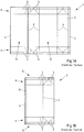
- Fig. 1A describes a blank 1 of a packaging material 2, as is known from the prior art.
- the packaging material 2 is formed as a laminate from a plurality of material layers arranged one above the other. It is in particular a cardboard / plastic composite.
- the packaging material 2 shown has two outer layers made of a thermoplastic, preferably polyethylene (PE), which enable the outer layers of the packaging material 2 to be sealed, ie welded. In between, a structuring cardboard layer is provided with a comparatively high bending stiffness for the packaging material 2.
- at least one barrier layer can also be provided, which is preferably formed from aluminum, polyamide and / or an ethylene-vinyl alcohol. Additional layers are also conceivable.
- the blank 1 is used to produce a packaging jacket 3, which is formed by the outer and opposite longitudinal edges 4 of the blank 1 being bent over and connected to one another, in particular sealed to one another.
- the blank 1 has a series of fold lines 5, 6 on which the blank 1 can be folded in order to form the desired package 7.
- Most of the fold lines 5, 6 are provided on the upper edge 8 and the lower edge 9 of the blank 1, which are later folded to form the bottom and the head or gable of the pack 7.
- the blank 1 has four essentially parallel fold lines 6, on which the blank 1 is pre-folded before the packaging jacket 3 is formed or after.
- the packing jacket 3 is shown on top of one another after the sealing of the longitudinal edges 4 of the blank 1.
- the corresponding sealing seam 10 is provided near one of the fold lines 6 of the packaging jacket 3.
- the packing jacket 3 has folded edges 6, around which the packing jacket 3 has been folded flat, so that the front section 11 and the rear section 12 of the packing jacket 3 lie one on top of the other.
- the packaging sleeves 3 can be easily stored in this way when folded flat. The subsequent unfolding around the four pre-folded fold lines 6 is then still easily possible.
- a packing jacket 3 with a rectangular cross section is then obtained.
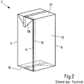
- the in the Fig. 2 Pack 7 shown can be obtained.
- the four pre-folded fold lines 6 then form the edges of the pack 7 in the region of the casing 13 of the pack 7, just as the pre-folded fold lines 6 previously formed the edges of the pack casing 3.
- the longitudinal ends 14, 15 of the package jacket 3 have been folded and sealed to form the bottom 16 of the package 7 and to form the head 17 of the package 7.
- So-called packing ears 18 are formed on the head 17 of the pack, which are folded down and placed on the jacket 13 of the pack 7 and sealed or glued there.
- the corresponding packing ears are folded inwards and are therefore no longer recognizable as such after the base 16 has been formed.
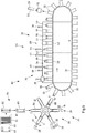
- the illustrated and in this respect preferred device 20 has a number of parallel processing lines, of which in the Fig. 3 only one processing line 23 is shown.
- Each processing line 23 is a magazine 22 with a stack 24. assigned a bundle of packing sleeves 3 folded flat around two of the folding lines 6.
- the packaging sleeves 3 have been formed as previously described from blanks 1 of a packaging material 2, the longitudinal edges 4 of which are sealed to one another.
- the packing sleeves 3 are unfolded by a feed device 25.
- the packaging sleeves 3 are unfolded by pulling away a later side surface of the corresponding packaging sleeve 3 from the stack 24 without further action around the pre-folded folding lines 6, which form the edges of the packaging sleeve 3 and of the later pack 7.
- an application device could also be provided for applying spouts (not shown) to the packing sleeves 3.
- the device 26 for forming the package 7 has a mandrel wheel 27 which, in the illustrated and in this respect preferred case, comprises six mandrels 28 and rotates counterclockwise cyclically, that is to say step by step.
- a packing jacket 3 is pushed onto the mandrel 28.
- the mandrel wheel 27 is rotated further in the next mandrel wheel position II, into which the longitudinal end 15 of the packing jacket 3 protruding relative to the mandrel 28 is heated with hot air by means of a heating unit 29.
- the heated longitudinal end 15 of the packing jacket 3 is pre-folded by a press 30 and in the following mandrel wheel position IV in the folded position it is sealed by a sealing device 31, in particular to form a base 16.
- a packing body 21 which is closed on one side is obtained, which is removed from the mandrel 28 in the subsequent mandrel wheel position V and transferred to a cell 32 of an endless transport device 33 guided in a circle.
- No working step is assigned to the mandrel 28 in the next mandrel wheel position VI.
- the number of mandrel wheel positions or mandrels 28 and the processing steps provided there can, if necessary, be as shown in FIG Fig. 1 and the associated description.
- a spout can be connected to the packaging material in at least one additional mandrel wheel position as required.
- the longitudinal end of the packing jacket closed on the mandrel wheel is preferably the head of the later packing. Whether the packing body is filled by the future head or by the future bottom plays only a minor role here.
- the packing body 21 taken from the mandrel wheel is transported with the open longitudinal end pointing upward in the associated cell 32, in particular a cell chain, by a filling machine 34.
- the package body then passes into an aseptic chamber 35, which comprises a sterilization zone 36 and a filling and sealing zone 37, through which the package bodies 21 are transported from left to right in the transport direction symbolized by the arrows.
- the packing bodies 21 do not have to be transported in a straight line, but can also be carried out in at least one arc or even in a circle.
- the packing bodies 21 are preheated in succession by a preheating device 39 by blowing with hot sterile air.
- the packing bodies 21 are then sterilized by means of a sterilizing device 40, preferably using hydrogen peroxide, whereupon the packing bodies 21 are dried by exposure to sterile air via a drying device 41 and after the transition from the sterilization zone 36 into the filling and sealing zone 37 into a filling position 42 below one Filling spout 43 are brought.
- There the packing bodies 2 are filled with food 44 one after the other.
- the filled ones Packing bodies 21 are then closed with a closing device 45 by folding the upper region of the packing body 21 and sealing.
- the filled and sealed packs 7 are then removed from the cells 32 of the transport device 33.
- the now empty cells 32 are moved further with the transport device 33 in the direction of the mandrel wheel 27 in order to accommodate further packing bodies 21 there.
- FIG. 4A A further blank 50 of a packaging material 51 is shown, which basically corresponds to the blank 50 with regard to the packaging material 51, the blank 50 and the fold lines 52, 53, 54 Fig. 1A resembles.
- the fold lines 52, 53, 54 in particular crease lines, are arranged and designed differently.
- only two fold lines 52 are provided, which extend in a straight line in the longitudinal direction and over the entire longitudinal extent of the blank 50.
- Two further fold lines 53 divide in sections in the longitudinal direction of the blank 50 and there enclose a portion of the blank. In the corresponding area, the fold lines 53 run parallel to one another, but this is not mandatory.
- the upper edge 55 and the lower edge 56 of the blank 50 are provided with fold lines 54.
- the fold lines 54 of the lower edge 56 serve to form a bottom 57, while the fold lines 54 of the upper edge 55 serve to form a head 58 of a package 59.
- the blank 50 is sealed along the longitudinal edges 60 to form a sealing seam 61 to form a packaging jacket 63, the front 64 and rear 64 'of which in the 4B-C are shown.
- the packing jacket 62 is folded on the two fold lines 52 which run in a straight line in the longitudinal direction of the packing jacket 62, forming the folding edges 65, so that the front side 64 and the rear side 64 'of the packing jacket 62 abut one another.
- the pack 59 has a flat bottom 57 which is oriented perpendicular to the longitudinal extent of the pack 59.
- the head 58 of the pack 59 is oriented obliquely to the longitudinal extent of the pack 59 and thus forms a pack gable 66.
- the pack gable 66 has a larger front gable surface 67 which is larger than the rear, smaller gable surface 71 arranged on the other side of the sealing seam 68
- the sealing seam 68 and adjoining sections of the head 58 form packing ears 69 on opposite sides of the packing 59, which are folded down and are attached or sealed to the jacket 70 of the packing 59.
- a larger opening section, a larger weakening and / or a large spout can be provided on the larger gable surface 67.
- neither an opening section nor a weakening or a spout is shown.
- the pack 59 no continuous fold lines 52 or fold edges 65 are provided on the front longitudinal edges of the pack 59.
- the folding edges 65 are not provided on any longitudinal edge of the pack 59 for folding the pack jacket 63 flat. Rather, the folded edges 65 are accommodated in the areas between the longitudinal edges or longitudinal edges of the pack 59. In other words, the folding edges 65 of the packaging jacket 63 are folded back again and thus no longer form folding edges of the packaging 59.
- no fold lines 52, 53, 54 extending straight in the longitudinal direction of the package are provided on the rear edges of the jacket 70 of the package 59.
- the fold lines 53 By dividing the fold lines 53, they do not run in a straight line over the entire longitudinal extent of the casing 70 of the pack 59 and also at least in sections not along the edges of the casing 70 of the pack 59, but in areas next to it.
- the device 80 for filling such packs 59 is shown.
- the device 80 largely corresponds to that in FIG Fig. 3 Device 20 shown, so that essentially the differences in the Fig. 6 device 80 compared to that shown in FIG Fig. 3 shown device 20 are described to avoid unnecessary repetitions. For this reason, the same components are in the Fig. 3 and 6 marked with the same reference numerals.
- the device 20 shown also has a pre-folding device 82 for pre-folding the packaging sleeves 63 after removing the packaging sleeves 63 from the stack 81 of the packaging sleeves 63, and a folding device 83 for unfolding the packaging sleeves 63, which are removed from the stack 81 of packaging sleeves 63 of the magazine 22.
- the pre-folding device 82 and the unfolding device 83 are combined in the illustrated and in this respect preferred device 80 to form a molding station 84 for molding the unfolded packaging jacket 63 to be transferred to the mandrel wheel 85.
- only the pre-folding device 82 or only the unfolding device 83 could be provided.
- the packing sleeves 63 are only pushed onto the mandrels 86 after they have passed through the forming station 84.
- the mandrels 86 are also different from those in the Fig. 3 illustrated thorns 28 formed.
- the mandrels 86 can namely be spread, that is to say adjusted from a narrower starting position to a wider pressing position, in the pressing position a pressing surface is provided by the mandrel 86, against which the corresponding longitudinal end 87 of the packing jacket 63 can be folded and pressed around the longitudinal end 87 to seal, in particular to seal liquid-tight.
- packing bodies 88 are ultimately formed which are delivered to the cells 32 of the transport device 33, here in the form of a cell chain.
- the in the Fig. 6 device 80 compared to that shown in FIG Fig. 3 Device 20 shown after a sealing device 89 for sealing the sealing seam 68 of the packing gable 66, a gable pre-folding device 90 for pre-folding the packing gable 66 and a sealing device 91 for sealing the Pack ears 69 provided on the jacket 70 of the pack 59.
- a shaping device 92 is provided for the final shaping of the filled and closed pack 59.
- the pack 59 receives its final shape in this shaping device 92.
- the molding device 92 is shown in such a way that the packing 59 protrudes above and below the molding device 92.
- the pack 59 is preferably received in the molding device 92 over its entire longitudinal extent.
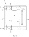
- FIG. 7 is schematically the molding station 84 of the in the Fig. 6 shown device 80 shown.
- the forming station 84 makes use of the packing sleeves 63, which are held ready in a magazine 81 in a stack 81 of packing sleeves 63 folded around two folding lines 52 or folding edges 65.
- the forming station 84 comprises a gripping arm 93 with suction cups 94, which grips the front side of the front flat-folded packing jacket 63 of the stack 81 and pulls the packing jacket 63 into and through a channel 95 of the pre-folding device 82.
- the prefolding device 82 is shown in particular in the sectional view of the forming station 84 Fig. 8 shown.
- the gripping arm 93 is shown in broken lines as it grips a packing jacket 63 of the stack 81.
- the gripping arm 93 then moves backwards in a straight line together with the packing jacket 63 and pulls the packing jacket 63 straight into a channel 95 which tapers transversely to the packing jacket 63.
- the folded edges 65 around which the packing jacket 63 has been folded flat, come into contact with the boundaries 96 of the channel 95.
- the folding edges 65 ultimately press from the inside against the channel 95, which in turn unfolds the packing jacket 63 somewhat, and the more, the further the packing jacket 63 is pulled or transported through the channel 95.
- grooves 97 aligned in the longitudinal direction of the folded edges 65 are provided on both sides of the channel 95, into which the packing jacket 63 engages with the folded edges 65 in the corresponding position.
- the suction cups 94 and thus the gripper arm 93 then detach from the packing jacket 63.
- the packing jacket 63 remains in the channel 95, held in the grooves 97.
- FIGS 9A-B shown in section.
- the mold 9 is shown by way of example with two mold halves 100, 101 in an open position. In this position, the pre-folded packing jacket 63 is taken over by the form 99, for which purpose grooves 102 are also provided in the illustrated and preferred form 99, in which the folded edges 65 of the packing jacket 63 engage.
- the packing jacket 63 is unfolded and at least essentially bears against the inner contour 103 of the mold 99.
- the packing jacket 63 can thus be brought at least approximately into the later shape of the packing 59.
- contours of a different shape can also be provided if necessary, depending on the form in which the packs are to be produced. In the Fig.
- a top view of the mandrel 86 of the mandrel wheel 85 is shown schematically.
- the mandrel 86 is in a starting position in which packing sleeves 63 can simply be pushed onto the mandrel 86 and removed again.
- the mandrel 86 does not have a rectangular or square cross section in sections.
- one side of the jacket 104 is curved outwards.
- Movable mandrel elements 106 and a static mandrel element 107 provided between them are provided on the head 105 of the illustrated and in this respect preferred mandrel 86.
- the movable mandrel elements 106 take an inner position a.
- the mandrel 86 is therefore narrower in a direction R than in that in FIG Figure 10B shown pressing position of the mandrel 86, in which the movable mandrel elements 106 are adjusted to the outside. In this position, the mandrel 86 is spread, wider and can be used to press a longitudinal end 87 of the packing jacket 63 against the mandrel 86. In the pressing position, the top of the head 105 of the mandrel 86 forms a pressing surface 108 for pressing the folded longitudinal end 87 of the packing jacket 63. The corresponding longitudinal end 87 of the packing jacket 63 can be closed, if necessary, by sealing.
- FIG. 11 schematically shows a gable pre-folding device 90 for pre-folding the packing gable 66, wherein a filled and closed packing 59 along the sealing seam 68 of the packing gable 66 is positioned in the gable pre-folding device 90 with packing ears 69 protruding outward from the jacket 70 of the packing.
- two punches 110 are pressed from opposite sides of the pack 59 against the casing 70 of the pack 59, so that the casing 70 of the pack 59 is pressed in at the corresponding point.
- the punches 110 engage below the protruding packing ears 69.
- the package 59 is partially folded on opposite fold lines 111 below the package ears 69.
- the pack ears 69 can be bent downward in a defined manner around the correspondingly pre-folded fold lines 111 and fixed there on the jacket 70 of the pack 59.
- a shaping device 92 is shown for shaping the filled and closed pack 59, in which the packing ears 69 are preferably already fixed to the jacket 70 of the pack 59.
- the package 59 is introduced into the opened mold 112 of a package squeezer comprising at least two mold halves 114, 115. Then the mold 112 is closed and the pack 59 is pressed or squeezed from the outside.
- the mold 112 can preferably accommodate the pack 59 over its entire longitudinal extent and / or overlap at the top and bottom, in order for example in the closed state of the mold 112 to To keep pack 59 not only over the entire circumference of the pack 59, but also all round in the longitudinal extent of the pack 59, in particular to press it.
- the inner contour 116 corresponds to the shape 112 of the desired shape of the pack 59 but not to the shape of the pack 59 supplied.
- the contour 116 is not the same as that shown in FIG Figures 12A-B shown form set. Different shaped contours can be provided to produce different shaped packs.
- the shape 112 has bevelled edges 113, which the pack 59 is also intended to have. When the mold 112 is closed, the pack 59 is pressed against the inner contour 116 of the mold 112 at least substantially all around and is folded or folded in the region of the bevelled edges 113 around fold lines 53 of the pack which have already been provided.
- the area of the pack 59 between the dividing fold lines 53 is thus brought into an oblique orientation to the sides and to the rear of the pack 59 in order to emboss the desired edge shape.
- the embossed edge shape is retained even after the package 59 has been removed from the mold 112, since the edge shape has already been created in the package 59 as a result of the fold lines 53. Only the packaging material 51 had not yet been folded or folded along the fold lines 53.
Landscapes
- Engineering & Computer Science (AREA)
- Mechanical Engineering (AREA)
- Making Paper Articles (AREA)
- Auxiliary Devices For And Details Of Packaging Control (AREA)
- Cartons (AREA)
- Closing Of Containers (AREA)
- Supplying Of Containers To The Packaging Station (AREA)
- Packages (AREA)
- Package Closures (AREA)
Description
Die Erfindung betrifft ein Verfahren zum Bilden von einseitig offenen Packungskörpern aus beidseitig offenen Packungsmänteln für die Herstellung von gefüllten Packungen nach dem Oberbegriff des Anspruchs 1. Ferner betrifft die Erfindung eine Vorrichtung zum Bilden von einseitig offenen Packungskörpern aus beidseitig offenen Packungsmänteln für die Herstellung von gefüllten Packungen nach dem Oberbegriff des Anspruchs 10.The invention relates to a method for forming packaging bodies which are open on one side from packaging casings which are open on both sides for the production of filled packs. The invention further relates to a device for forming packaging bodies which are open on one side from packaging casings which are open on both sides for the production of filled packs according to the preamble of
Verfahren und Vorrichtungen zum Bilden von einseitig offenen Packungskörpern aus beidseitig offenen Packungsmänteln sind bereits seit geraumer Zeit bekannt. Die Verfahren dienen insbesondere dem Herstellen von gefüllten Packungen, wobei auch Verfahren und Vorrichtungen zum Füllen von Packungen mit Produkten in unterschiedlichen Ausgestaltungen bekannt sind.Methods and devices for forming packaging bodies that are open on one side from packaging casings that are open on both sides have been known for some time. The methods are used, in particular, to produce filled packs, and processes and devices for filling packs with products in different configurations are also known.
Unter Packungskörpern werden in diesem Zusammenhang Behälter wie beispielsweise Kartonverbundverpackungen verstanden, die wenigstens teilweise aus einem Packstoff in Form eines Laminat umfassend eine Kartonschicht und äußeren, insbesondere thermoplastischen, Kunststoffschichten, etwa aus Polyethylen (PE), gebildet sind. Der Karton verleiht den Packungen eine ausreichende Stabilität, damit die Packungen einfach gehandhabt und beispielsweise gestapelt werden können. Die Kunststoffschichten schützen den Karton vor Feuchtigkeit und die Lebensmittel vor der Aufnahme von unerwünschten Stoffen aus der Packung. Zusätzlich können noch weitere Schichten, wie etwa eine Aluminiumschicht, vorgesehen sein, die eine Diffusion von Sauerstoff und anderen Gasen durch die Packstoff verhindert.In this context, package bodies are understood to mean containers such as, for example, composite cardboard packaging, which are at least partially formed from a packaging material in the form of a laminate comprising a cardboard layer and outer, in particular thermoplastic, plastic layers, for example of polyethylene (PE). The carton gives the packs sufficient stability so that the packs can be handled easily and, for example, stacked. The plastic layers protect the cardboard from moisture and the food from the absorption of unwanted substances from the pack. In addition, you can additional layers, such as an aluminum layer, can be provided which prevent diffusion of oxygen and other gases through the packaging material.
Entsprechende Packungskörper werden typischerweise mit Produkten in Form von Lebensmitteln, insbesondere Getränken, gefüllt, wobei als Produkte überwiegend fließfähige Produkte in Frage kommen. Dabei erfolgt insbesondere das Befüllen der Packungskörper mit Lebensmitteln in einer sterilen oder aseptischen Umgebung einer Füllmaschine, da die Lebensmittel nach dem Füllen der Packungen lange haltbar sein sollen. Hierzu weisen die Füllmaschinen beispielsweise Sterilisationsräume bzw. Aseptikkammern auf, in denen die Packungskörper sterilisiert und anschließend unter möglichst sterilen Bedingungen gefüllt sowie verschlossen werden. Nach dem Befüllen der Packungskörper werden diese typischerweise in der Füllmaschine verschlossen. Bei Verwendung entsprechender Packstoffe, erfolgt das Verschließen des Packungskörpers durch Siegeln des offenen Endes.Corresponding packing bodies are typically filled with products in the form of foodstuffs, in particular beverages, the flow products being predominantly products. In particular, the packing bodies are filled with food in a sterile or aseptic environment of a filling machine, since the food should be kept for a long time after the packs have been filled. For this purpose, the filling machines have, for example, sterilization rooms or aseptic chambers in which the packing bodies are sterilized and then filled and sealed under as sterile conditions as possible. After the packing bodies have been filled, they are typically sealed in the filling machine. When using appropriate packaging materials, the package body is closed by sealing the open end.
Die Packungskörper werden vorzugsweise auf der Füllmaschine aus Packungsmänteln gebildet, die wiederum aus Packstoffzuschnitten hergestellt werden, und zwar insbesondere durch Siegeln der Längskanten der Packstoffzuschnitte aufeinander. Die innere Längskante kann dabei nach außen umgelegt werden, um ein Eindringen von Feuchtigkeit in den Packstoff, insbesondere den Karton, zu vermeiden So werden aus einem Packstoff gebildete Packungsmäntel hergestellt, die an den gegenüberliegenden Längsenden offen sind. Die Packungsmäntel werden entlang von vier längs zum Packungsmantel verlaufenden Faltlinien vorgefaltet, wodurch Faltkanten geschaffen werden, welche die späteren Kanten der typischerweise einen quadratischen oder rechteckigen Querschnitt bildenden Packung bilden. Zunächst werden die Packungsmäntel jedoch um zwei gegenüberliegende Faltkanten flach gefaltet. Zwei der vorgefalteten Faltlinien werden dabei wieder zurückgefaltet. Der Packungsmantel bildet dann im Wesentlichen zwei parallel zueinander verlaufende und aufeinander liegende Abschnitte. Die flachgefalteten Packungsmäntel werden als Stapel an ein Magazin der Füllmaschine übergeben. Der vordere Abschnitt des Packungsmantels am vorderen Ende des Stapels wird von Saugnäpfen ergriffen und vom Stapel weg gezogen, wobei sich der Packungsmantel auffaltet, typischerweise bis ein wenigstens im Wesentlichen quadratischer oder rechteckiger Querschnitt gebildet ist. Das Auffalten erfolgt entlang der vorgefalteten Faltlinien, von denen zwei die Faltkanten des zusammengefalteten Packungsmantels gebildet haben, da der Packstoff entlang der, insbesondere vorgefalteten, Faltlinien leicht geknickt bzw. gefaltet werden kann. Der entsprechend aufgefaltete Packungsmantel wird sodann auf einen Dorn eines sogenannten Dornrades aufgezogen, wobei der Querschnitt des Dorns dem Querschnitt des Packungsmantels entspricht. Der Packungsmantel steht dabei zunächst über den Dorn nach außen vor, so dass der vorstehende Teil des Packungsmantels gegen die Stirnseite des Dorns gefaltet und dort verpresst und gesiegelt werden kann. Das entsprechende Längsende des Packungsmantels wird so verschlossen und bildet regelmäßig den Boden der späteren gefüllten Packung. Das verschlossene Ende des Packungsmantels könnte alternativ aber auch den Kopf der späteren Packung bilden, wenn diese beispielsweise durch den offenen Boden gefüllt wird.The packing bodies are preferably formed on the filling machine from packing sleeves, which in turn are made from packaging blanks, in particular by sealing the longitudinal edges of the packaging blanks to one another. The inner longitudinal edge can be folded outwards in order to prevent moisture from penetrating into the packaging material, in particular the carton. Thus, packaging shells are made from a packaging material that are open at the opposite longitudinal ends. The pack sleeves are pre-folded along four fold lines running longitudinally to the pack sleeve, creating fold edges which form the later edges of the pack, which typically forms a square or rectangular cross section. First, however, the packaging sleeves are folded flat around two opposite folding edges. Two of the pre-folded fold lines are folded back. The packing jacket then essentially forms two sections running parallel to one another and lying one on top of the other. The flat-folded packaging sleeves are transferred as a stack to a magazine on the filling machine. The front section of the packaging jacket at the front end of the stack is gripped by suction cups and away from the stack pulled, the packing jacket unfolding, typically until an at least substantially square or rectangular cross section is formed. The unfolding takes place along the pre-folded folding lines, two of which have formed the folding edges of the folded-up packaging jacket, since the packaging material can be easily folded or folded along the, in particular pre-folded, folding lines. The correspondingly unfolded packing jacket is then pulled onto a mandrel of a so-called mandrel wheel, the cross section of the mandrel corresponding to the cross section of the packing jacket. The packing jacket protrudes outward beyond the mandrel so that the protruding part of the packing jacket can be folded against the end face of the mandrel and pressed and sealed there. The corresponding longitudinal end of the packaging jacket is closed and regularly forms the bottom of the later filled package. Alternatively, the closed end of the package jacket could also form the head of the later package if it is filled through the open bottom, for example.
Die einseitig offenen Packungskörper werden in eine Sterilisationszone der Füllmaschine eingeschleust. Dies erfolgt meist, indem die Packungskörper nacheinander an die Packungskörper aufnehmenden Zellen einer Transporteinrichtung übergeben werden. Die Transporteinrichtung sorgt dann dafür, dass die Packungskörper mit definierter Geschwindigkeit in definiertem Abstand zueinander durch die Sterilisationszone der Füllmaschine transportiert werden. In der Sterilisationszone werden die Packungskörper mit heißer Sterilluft vorgewärmt und sodann, typischerweise mit Wasserstoffperoxid, sterilisiert und mit Sterilluft getrocknet. Die sterilen Packungskörper werden in die Füll- und Siegelzone übergeben und dort befüllt. Anschließend wird die Öffnung der gefüllten Packungskörper verschlossen, bevor die verschlossene Packung über die Transporteinrichtung aus der Füll- und Siegelzone transportiert und anschließend aus den entsprechenden Zellen der Transporteinrichtung entnommen wird.The packaging bodies, which are open on one side, are introduced into a sterilization zone of the filling machine. This is usually done by successively transferring the package bodies to the cells of a transport device that receive the package bodies. The transport device then ensures that the package bodies are transported through the sterilization zone of the filling machine at a defined speed and at a defined distance from one another. In the sterilization zone, the package bodies are preheated with hot sterile air and then sterilized, typically with hydrogen peroxide, and dried with sterile air. The sterile packing bodies are transferred to the filling and sealing zone and filled there. The opening of the filled packing bodies is then closed before the closed packing is transported out of the filling and sealing zone via the transport device and is then removed from the corresponding cells of the transport device.
In einigen Füllmaschinen werden die Packungskörper von der Transporteinrichtung in einer geraden Linie durch die Füllmaschine transportiert. Entsprechende Füllmaschinen werden auch als Langläufer bezeichnet. In anderen Fülleinrichtungen, den sogenannten Rundläufern, beschreiben die Packungskörper eine mehr oder weniger bogenförmige Bewegung, die ein oder mehr Kreisbogenabschnitte umfassen kann. Die vorliegende Erfindung betrifft grundsätzlich beide Arten von Füllmaschinen. Das Verfahren und die Vorrichtung jeweils der zuvor beschriebenen Art haben sich für die Fertigung von Packungen mit wenigstens im Wesentlichen rechteckigen oder quadratischen Querschnitten bewährt. Die Fertigung von Packungen mit hiervon deutlich abweichenden Querschnitten ist jedoch nur bedingt oder gar nicht möglich. Die Packungsmäntel müssen aus Platzgründen flach zusammengefaltet und anschließend mittels des Dornrads einfach und zuverlässig geformt werden. Zudem muss es die Form der Packungen erlauben, dass die Packungsmäntel leicht auf das Dornrad gelangen und die Packungskörper zuverlässig wieder vom Dornrad entfernt werden können.In some filling machines, the packing bodies are transported by the transport device in a straight line through the filling machine. Corresponding filling machines are also called cross-country skiers. In other filling devices, the so-called rotary machines, the packing bodies describe a more or less arc-shaped movement, which can comprise one or more circular arc sections. The present invention basically relates to both types of filling machines. The method and the device of the type described above have proven themselves for the production of packs with at least substantially rectangular or square cross sections. However, the production of packs with cross sections that differ significantly therefrom is only possible to a limited extent or not at all. The packing sleeves have to be folded flat for reasons of space and then simply and reliably formed using the mandrel wheel. In addition, the shape of the packs must allow the pack sleeves to easily reach the mandrel wheel and the pack bodies to be reliably removed from the mandrel wheel.
Ferner sind ein Verfahren und eine Vorrichtung der eingangs genannten Art aus
Daher liegt der vorliegenden Erfindung die Aufgabe zugrunde, das Verfahren und die Vorrichtung jeweils der eingangs genannten Art derart auszugestalten und weiterzubilden, dass auch Packungen mit einem weder quadratischen noch rechteckigen Querschnitt einfach und zuverlässig gebildet werden können.The present invention is therefore based on the object of designing and developing the method and the device of the type mentioned at the outset in such a way that packs with a cross section which is neither square nor rectangular can be formed simply and reliably.
Diese Aufgabe wird gemäß Anspruch 1 durch ein Verfahren zum Bilden von einseitig offenen Packungskörpern aus beidseitig offenen Packungsmänteln für die Herstellung von gefüllten Packungen dadurch gelöst, dass die Packungsmäntel in der Formstation durch einen mit den zwei gegenüberliegenden Faltkanten des Packungsmantels in Anlage kommenden und sich quer zum Packungsmantel verjüngenden Kanal gezogen werden, wobei die Packungsmäntel am Ende des Kanals in gegenüberliegenden Seiten des Kanals zugeordneten Nuten eingreifen.This object is achieved according to
Die genannte Aufgabe wird zudem bei einer Vorrichtung nach dem Oberbegriff des Anspruchs 10 dadurch gelöst, dass die Formstation einen Kanal zum teilweisen Auffalten der durch den Kanal bewegten Packungsmäntel aufweist und dass am Ende des Kanals gegenüberliegende Nuten zur Aufnahme der Faltkanten der Packungsmäntel vorgesehen sind.The above object is also achieved in a device according to the preamble of
Es ist also erkannt worden, dass es zweckmäßig sein kann, die Packungsmäntel nicht beim Entnehmen vom Packungsstapel aufzufalten und direkt an die Dorne eines Dornrads zu übergeben, sondern für das Auffalten der Packungsmäntel eine separate Formstation zu verwenden. Um die Packungsmäntel mit dem Entnehmen vom Stapel ohne Weiteres auffalten zu können, bedarf es vier vorgefalteter Faltlinien. Wird die vordere Seite des am vorderen Ende des Packungsstapels vorgesehenen Packungsmantels, etwa mit einem mit Saugnäpfen besetzten Greifarm, ergriffen und vom Stapel gezogen, faltet der Packungsmantel auf, wobei die Faltkanten die Kanten des aufgefalteten Packungsmantels bilden. Dies ist ein bewährtes Verfahren, jedoch bestimmen die Faltkanten die Querschnittsform des Packungsmantels nicht unwesentlich mit.It has thus been recognized that it may be expedient not to unfold the packing sleeves when removing them from the stack of packs and to transfer them directly to the mandrels of a mandrel wheel, but to use a separate forming station for unfolding the packing sleeves. In order to be able to easily unfold the packaging sleeves when removing them from the stack, four pre-folded folding lines are required. If the front side of the packaging sleeve provided at the front end of the stack of packs, for example with a gripping arm fitted with suction cups, is gripped and pulled from the stack, the packaging jacket folds up, the folded edges forming the edges of the unfolded packaging jacket. This is a tried-and-tested method, but the folded edges also have a significant influence on the cross-sectional shape of the packaging jacket.
Die Verwendung der Formstation erlaubt dagegen den Einsatz von Packungsmänteln mit bedarfsweise lediglich zwei Faltkanten, die dem Flachfalten der Packungsmäntel zur Aufnahme in einem Stapel dienen. Darüber hinaus müssen die beiden Faltkanten aber nicht über die Form, insbesondere den Querschnitt, der späteren Packung bestimmen. In der Formstation können die Packungsmäntel in die gewünschte Form gebracht werden, ohne dass dabei die Faltkanten in Ecken der Packung oder an Kanten des Mantels der Packung angeordnet sein müssen. Die Faltkanten können beispielsweise in ebenen Abschnitten des Mantels der Packung angeordnet sein, um die Kanten des Mantels der Packung unabhängig von der Lage der Faltkanten bereitstellen zu können oder um scharfe Kanten teilweise oder bedarfsweise gänzlich zu vermeiden. Die Kantenbereiche der Mäntel der Packungen können in der Formstation so mit einem sehr großen Radius gebildet werden und auch gewölbte Seitenwände des Mantels der Packung können einfacher gebildet werden, und zwar alternativ oder zusätzlich.The use of the forming station, on the other hand, allows the use of packing sleeves with only two folding edges, if necessary, which serve to fold the packing sleeves flat to accommodate them in a stack. In addition, the two folded edges do not have to determine the shape, in particular the cross section, of the later pack. In the forming station, the pack sleeves can be brought into the desired shape without the folded edges having to be arranged in corners of the pack or on edges of the jacket of the pack. The folded edges can be arranged, for example, in flat sections of the casing of the pack, around the edges of the casing of the pack, regardless of the position of the folded edges to be able to provide or to avoid sharp edges partially or completely if necessary. The edge regions of the shells of the packs can thus be formed with a very large radius in the forming station, and curved side walls of the sheath of the pack can also be formed more easily, alternatively or additionally.
Damit das Falten der Packungsmäntel entlang der wenigstens zwei Faltkanten zu einem flachen Packungsmantel einfach und zuverlässig erfolgt, werden entlang der Faltkanten zunächst sogenannte Faltlinien vorgesehen. Der Packungsmantel weist dabei bevorzugt weitere Faltlinien oder Rilllinien auf, die etwa dem Falten der Längsenden des Packungsmantels zum Zwecke des Verschließens des Packungsmantels dienen. Dabei werden bevorzugt durch Falten entlang der weiteren Faltlinien ein Kopf und ein Boden der Packung gebildet, die insbesondere gesiegelt werden. Die Faltlinien oder Rilllinien sind dabei vorzugsweise in den Packstoff eingeprägt, und zwar insbesondere durch sogenanntes Rillen, weshalb die so hergestellten Faltlinien auch als Rilllinien bezeichnet werden können. Die Faltlinien oder Rilllinien werden durch eine linienförmige Stoffverdrängung mit Werkzeugen geschaffen, die gegen den Packstoff drücken, etwa mit Stanz- oder Drückwerkzeugen. Mit anderen Worten bilden die Faltlinien oder Rilllinien linienartige Materialschwächungen des Packstoffs. Entlang der so hergestellten Faltlinien ist die Biegefähigkeit des Packstoffs erhöht.So that the packaging sleeves can be folded easily and reliably along the at least two folding edges to form a flat packaging sleeve, so-called folding lines are initially provided along the folding edges. The packaging jacket preferably has further fold lines or creasing lines, which serve, for example, to fold the longitudinal ends of the packaging jacket for the purpose of closing the packaging jacket. In this case, a head and a bottom of the pack are preferably formed by folding along the further fold lines, and are sealed in particular. The fold lines or crease lines are preferably stamped into the packaging material, in particular by so-called creasing, which is why the fold lines produced in this way can also be referred to as crease lines. The fold lines or crease lines are created by means of a line-shaped material displacement with tools that press against the packaging material, for example with punching or pressing tools. In other words, the fold lines or crease lines form line-like material weakenings of the packaging material. The bendability of the packaging material is increased along the fold lines thus produced.
Unabhängig von der Anzahl der Faltkanten des Packungsmantels, wobei jedoch ebenfalls genau zwei Faltkanten bevorzugt sind, kann zwischen den Faltkanten vollständig auf entsprechende Faltlinien verzichtet werden, die sich geradlinig in Längsrichtung, also wenigstens im Wesentlichen parallel zu den Faltkanten erstrecken, und zwar über die gesamte Längserstreckung des Packungsmantels. So ergibt sich eine höhere Flexibilität bei der Wahl der Form der Packung. Weitere geradlinig verlaufende Faltlinien und Faltkanten sind wegen der Formstation für das Auffalten der Packungsmäntel nach dem Entnehmen vom Packungsstapel nicht erforderlich. Vorzugsweise sind zusätzlich zu den Faltkanten keine weiteren vorgefalteten Faltlinien des Packungsmantels vorgesehen, jedenfalls keine geradlinig über die gesamte Längserstreckung des Packungsmantels verlaufende Faltlinien. Das Vorfalten entsprechender Faltlinien, also insbesondere das Falten des Packstoffs um die Faltlinien vor dem eigentlichen Falten der Faltlinien mit anschließendem Zurückfalten, erfolgt bei bekannten Verfahren vor dem Stapeln der Packungsmäntel damit die Packungsmäntel nach dem Entnehmen vom Stapel um die vorgefalteten Faltlinien leichter auffalten. Das ist vorliegend wegen der Formstation und dem Auffalten der Packungsmäntel darin nicht erforderlich. Wenn also in Längsrichtung des Packungsmantels durchgehend geradlinig geführte Faltlinien zusätzlich zu den Faltkanten vorgesehen sein sollten, was grundsätzlich entbehrlich ist, sind diese bevorzugt nicht vorgefaltet.Regardless of the number of folded edges of the packaging jacket, although exactly two folded edges are also preferred, there is no need for corresponding fold lines between the folded edges, which extend in a straight line in the longitudinal direction, i.e. at least substantially parallel to the folded edges, and that over the entire Length of the packaging jacket. This results in greater flexibility in the choice of the shape of the pack. Further straight folding lines and folding edges are not necessary because of the forming station for unfolding the packaging sleeves after removal from the stack of packs. In addition to the folded edges, there are preferably no further ones pre-folded folding lines of the packaging jacket are provided, in any case no folding lines running straight over the entire longitudinal extent of the packaging jacket. In known methods, prior folding of the packaging material around the folding lines before the actual folding of the folding lines with subsequent folding back takes place, prior to stacking the packaging sleeves, so that the packaging sleeves are easier to unfold around the pre-folded folding lines after removal from the stack. This is not necessary in the present case because of the forming station and the unfolding of the packing sleeves. If, in the longitudinal direction of the packaging jacket, there should be continuous, straight folding lines in addition to the folding edges, which is fundamentally unnecessary, these are preferably not prefolded.
Grundsätzlich bedarf es jedoch keiner weiteren Faltlinien zur Herstellung entsprechender Faltungen des Packungsmantels. Da es an Faltlinien und/oder Faltkanten der fertigen Packung zu Falten oder Knicken im Packstoff kommen kann, können durch die Verringerung der Anzahl an Faltlinien und/oder Faltkanten breitere Bereiche der Packung ohne unerwünschte Knicke oder Faltungen geschaffen werden, was unter Umständen bevorzugt ist. Die Packungen können in diesen Bereichen beispielsweise gleichförmig gewölbt, gerundet und/oder gekrümmt sein, ohne dass diese Form durch Knicke oder Falten beeinträchtigt wird.Basically, however, no further folding lines are required to produce corresponding folds of the packaging jacket. Since folding lines and / or folding edges of the finished package can cause folds or kinks in the packaging material, by reducing the number of folding lines and / or folding edges, wider areas of the package can be created without undesired kinks or folds, which may be preferred. The packs can, for example, be uniformly curved, rounded and / or curved in these areas without this shape being impaired by kinks or folds.
Bevorzugt handelt es sich bei den wenigstens zwei Faltlinien oder Rilllinien, die dem Flachfalten des Packungsmantels dienen und demnach die wenigstens zwei Faltkanten des Packungsmantels bilden, um sogenannte "Scheinfaltlinien", die später keine Kante der Verpackung bzw. Packung bilden. Eine Faltung entlang der Scheinfaltlinien erfolgt daher nur zur Bildung des Packungsmantels, nicht jedoch bei der daraus hergestellten Verpackung, die zusammen mit der Füllung die Packung bilden kann. Diese Scheinfaltlinien sollen - wie auch herkömmliche Faltlinien - das Falten des Packungsmantels erleichtern. Diese Faltlinien werden als "Scheinfaltlinien" bezeichnet, da diese nur beim Flachfalten des Packungsmantels genutzt werden, jedoch beim Auffalten zur Herstellung des Packungskörpers bzw. der zu befüllenden Verpackung wieder wenigstens in etwa gerade gefaltet werden. Sie können durch Materialschwächungen erzeugt werden, wobei zum Erhalt des flüssigkeitsdichten Zustandes des Verbundmaterials keine Perforationen, sondern sogenannte "Rillungen" verwendet werden können. Rillungen sind linienförmige Materialverdrängungen, die mit Stanz- oder Drückwerkzeugen in das Verbundmaterial eingeprägt oder eingerollt werden. Die beiden Scheinfaltlinien sind gerade und verlaufen parallel zueinander. Der Packungsmantel ist entlang der wenigstens zwei Scheinfaltlinien gefaltet, die somit die Faltkanten bilden.The at least two fold lines or crease lines, which serve for the flat folding of the packaging jacket and accordingly form the at least two folding edges of the packaging jacket, are preferably so-called "false folding lines" which later do not form an edge of the packaging or packaging. Folding along the false fold lines therefore only takes place to form the packaging jacket, but not in the packaging produced therefrom, which together with the filling can form the packaging. These false fold lines - like conventional fold lines - should make it easier to fold the packaging jacket. These fold lines are referred to as "false fold lines" because they are only used when the packaging jacket is folded flat, but when it is unfolded to produce the package body or those to be filled Packaging should be folded at least approximately straight again. They can be produced by weakening the material, whereby, in order to maintain the liquid-tight state of the composite material, it is not possible to use perforations, but so-called "creases". Creases are linear material displacements that are stamped or rolled into the composite material using punching or pressing tools. The two false fold lines are straight and run parallel to each other. The packaging jacket is folded along the at least two false fold lines, which thus form the folded edges.
Es können jedoch auch weitere Faltlinien vorgesehen sein. Insbesondere handelt es sich dabei aber um solche, die sich nicht oder nur über einen Teil der Längserstreckung des Packungsmantels geradlinig erstrecken. Diese können entsprechend geformte Kanten bilden, die beispielsweise das Halten und Ergreifen der späteren Packung erleichtern. Auch dadurch wird eine erhöhte Flexibilität bei der Wahl der Form der Packung erreicht, ohne dass trotzdem an den bekannten vier vorgeformten Faltlinien zum Auffalten des Packungsmantels festgehalten werden müsste.However, further fold lines can also be provided. In particular, however, these are those which do not extend or only extend in a straight line over part of the longitudinal extent of the packaging jacket. These can form correspondingly shaped edges which, for example, make it easier to hold and grip the later pack. This also results in increased flexibility in the choice of the shape of the pack, without having to adhere to the known four preformed folding lines for unfolding the pack jacket.
Insbesondere wird die Verwendung eines Packungsmantels gemäß den von der Anmelderin unter den amtlichen Aktenzeichen
Die Übergabeeinrichtung kann beispielsweise als Greifarm ausgebildet sein oder einen Greifarm umfassen. Alternativ oder zusätzlich kann die Übergabeeinrichtung wenigstens einen Finger umfassen der an einem Packungsmantel angreifen und den Packungsmantel somit verschieben kann. Andere bekannte Übergabeeinrichtungen sind jedoch ebenfalls denkbar. Die Aufschiebeeinrichtung kann ebenfalls wenigstens einen Finger zum Ergreifen des Packungskantens und Aufschieben des Packungsmantels auf den Dorn umfassen. Der Packungsmantel kann aber auch direkt von einer Form zum Auffalten des Packungsmantels an den Dorn übergeben werden, so dass die Aufschiebeeinrichtung zum entsprechenden Bewegen der Form über den Dorn ausgebildet sein kann. Andere bekannte Aufschiebeeinrichtungen sind jedoch ebenfalls denkbar.The transfer device can for example be designed as a gripping arm or comprise a gripping arm. As an alternative or in addition, the transfer device can comprise at least one finger which can engage a packaging jacket and thus shift the packaging jacket. Other known transfer devices are also conceivable. The push-on device can also comprise at least one finger for gripping the packing edge and pushing the packing casing onto the mandrel. However, the packing jacket can also be transferred directly from a mold to the mandrel to unfold the packing jacket, so that the push-on device can be designed to move the mold appropriately over the mandrel. However, other known slide-on devices are also conceivable.
Nachfolgend werden der besseren Verständlichkeit halber und zur Vermeidung unnötiger Wiederholungen das Verfahren und die Vorrichtung zusammen beschrieben, ohne jeweils im Einzelnen zwischen dem Verfahren und der Vorrichtung zu unterscheiden. Dem Fachmann wird jedoch anhand des Kontextes ersichtlich, welche Merkmale für das Verfahren und die Vorrichtung jeweils bevorzugt sind.For the sake of clarity and in order to avoid unnecessary repetitions, the method and the device are described together below, without each differentiating in detail between the method and the device. The person skilled in the art, however, can see from the context which features are preferred for the method and the device.
Bei einer ersten besonders bevorzugten Ausgestaltung des Verfahrens werden die Packungsmäntel um genau zwei Faltkanten flach gefaltet. Dies erlaubt das platzsparende Bevorraten der Packungsmäntel in einem Stapel. Außerdem müssen die Packungsmäntel dann nur um zwei Faltkanten gefaltet werden. Bevorzugt handelt es sich bei den beiden Faltlinien zur Bildung der Faltkanten um "Scheinfaltlinien" der beschriebenen Art, die also später keine Kante der Verpackung bzw. Packung bilden. Eine Faltung entlang der Scheinfaltlinien erfolgt daher nur beim Packungsmantel, nicht jedoch bei der daraus hergestellten Verpackung bzw. Packung..In a first particularly preferred embodiment of the method, the packaging sleeves are folded flat by exactly two folded edges. This allows space-saving storage of the packaging sleeves in a stack. In addition, the packaging sleeves then only have to be folded over two folded edges. The two fold lines for forming the fold edges are preferably "false fold lines" of the type described, which therefore do not later form an edge of the packaging or pack. Folding along the false fold lines therefore only takes place in the case of the packaging, but not in the packaging or packaging produced therefrom.
Es können jedoch auch in diesem Fall weitere Faltlinien vorgesehen sein. Insbesondere handelt es sich dabei aber wiederum um solche, die sich nicht oder nur über einen Teil der Längserstreckung des Packungsmantels geradlinig erstrecken. Diese können entsprechend geformte Kanten bilden, die beispielweise das Halten und Ergreifen der späteren Packung erleichtern. Auch dadurch wird eine erhöhte Flexibilität bei der Wahl der Form der Packung erreicht, ohne dass trotzdem an den bekannten vier vorgeformten Faltlinien zum Auffalten des Packungsmantels festgehalten werden müsste.However, further fold lines can also be provided in this case. In particular, however, these are again those which do not extend or only extend in a straight line over part of the longitudinal extent of the packaging jacket. These can form correspondingly shaped edges which, for example, make it easier to hold and grip the later pack. This also results in increased flexibility in the choice of the shape of the pack, without having to adhere to the known four preformed folding lines for unfolding the pack jacket.
Alternativ oder zusätzlich werden in der Formstation die wenigstens zwei Faltkanten, insbesondere die genau zwei Faltkanten, des Packungsmantels, um die der Packungsmantel zuvor flach gefaltet worden ist, aufeinander zubewegt, wobei sich der freie Querschnitt des Packungsmantels entsprechend vergrößert. Es kann so einfach ein wenigstens teilweises Auffalten des Packungsmantels erreicht werden, ohne dass es dafür mehr als zwei Faltkanten bzw. mehr als zwei vorgefaltete Faltlinien, wie bei den bekannten Packungsmänteln bedarf. Bei bekannten Packungsmänteln sind vier vorgefaltete Faltlinien vorhanden, die das Auffalten des Packungsmantels nach dem Entnehmen vom Stapel der Packungsmäntel vereinfachen, Diese vier vorgefalteten Faltlinien bilden dabei die Faltkanten des Packungsmantels. Die vorliegende Formstation macht derartige Packungsmäntel entbehrlich. Dabei bietet es sich der Einfachheit halber an, dass in der Formstation von außen gegen die wenigstens zwei Faltkanten gedrückt oder gepresst wird. Die Faltkanten können so unter Vergrößerung des freien Querschnitts der Packung aufeinander zubewegt bzw. bezogen auf den zugehörigen Packungsmantel nach innen gedrückt werden. So kann beispielsweise von gegenüberliegenden Seiten des Packungsmantels gegen die wenigstens zwei Faltkanten gedrückt werden, so dass sich diese annähern, aber vorzugsweise nicht in Anlage aneinander kommen, da dies typischerweise wieder mit einer Verringerung des freien Querschnitts des Packungsmantels einhergehen würde.As an alternative or in addition, the at least two folding edges, in particular the exactly two folding edges, of the packaging jacket, around which the packaging jacket has previously been folded flat, are moved towards one another in the forming station, the free cross section of the packaging jacket increasing accordingly. An at least partial unfolding of the packaging jacket can be achieved in this way without requiring more than two folding edges or more than two pre-folded folding lines, as in the known packaging jackets. In known packaging sleeves, there are four pre-folded folding lines which simplify the unfolding of the packaging sleeve after removal from the stack of packaging sleeves. These four pre-folded folding lines form the folding edges of the packaging sleeve. The present molding station makes such packaging sleeves unnecessary. For the sake of simplicity, it makes sense to press or press from the outside against the at least two folded edges. The folded edges can thus be moved toward one another while increasing the free cross-section of the pack, or can be pressed inwards with respect to the associated pack jacket. For example, it is possible to press against the at least two folded edges from opposite sides of the packaging jacket, so that they converge, but preferably do not come into contact with one another, since this would typically be accompanied by a reduction in the free cross section of the packaging jacket.
Für ein gezieltes und definiertes Auffalten eines Packungsmantels in der Formstation, kann der Packungsmantel in der Formstation zwischen wenigstens zwei Formhälften einer Form positioniert werden. Beim Schließen der durch die wenigstens zwei Formhälften gebildeten Form oder wenigstens beim Bewegen der wenigstens zwei Formhälften aufeinander zu wird der Packungsmantel aufgefaltet. Durch das Schließen der Formhälften drücken diese gegen die Faltkanten des Packungsmantels und bedingen so das Auffalten des Packungsmantels. Dabei legt sich der Packungsmantel vorzugsweise wenigstens im Wesentlichen umlaufend an die Innenseite der Form an, so dass der Packungsmantel eine definierte Form erhält. Die Form kann grundsätzlich auch aus mehren Teilen als den beiden Formhälften gebildet werden, oder es werden die Formhälften bedarfsweise aus mehreren Teilen gebildet. Es bietet sich aber an, wenn zwei Teile zusammen den, insbesondere weit, überwiegenden Teil der Form bilden.For a targeted and defined unfolding of a packaging jacket in the molding station, the packaging jacket can be positioned in the molding station between at least two mold halves of a mold. When the mold formed by the at least two mold halves is closed or at least when the at least two mold halves are moved towards one another, the packing jacket is unfolded. By closing the mold halves, they press against the folded edges of the packaging jacket and thus cause the packaging jacket to be unfolded. In this case, the packing jacket preferably lies against the inside of the mold at least substantially all around, so that the packing jacket takes on a defined shape. In principle, the mold can also be formed from several parts than the two mold halves be, or the mold halves are formed from several parts if necessary. However, it is advisable for two parts to form the predominant part of the shape, particularly the large part.
Um die zunächst flach gefalteten Packungsmäntel aufzufalten, kann die Vorderseite des an der Vorderseite des Stapels aus Packungsmänteln vorgesehen Packungsmantels ergriffen und nach vorne vom Stapel weg bewegt werden. Vorne wird in diesem Zusammenhang die in Richtung der Transportrichtung weisende Seite des Stapels bzw. des Packungsmantels verstanden. Dies trägt dem Umstand Rechnung, dass die Packungsmäntel im Stapel typischerweise aufrecht stehen. Denkbar wäre aber beispielsweise auch, dass die flach gefalteten Packungsmäntel aufeinander liegen. Dann wäre die Oberseite des Stapels nach vorliegendem Verständnis als die Vorderseite des Stapels anzusehen. Dementsprechend würde zudem die nach oben weisende Seite des oberen Packungsmantels die nach vorne weisende Seite des vorderen Packungsmantels bilden. Auf die Ausrichtung des Stapels kommt es also nicht wesentlich an.In order to unfold the packaging sleeves, which are initially folded flat, the front of the packaging sleeve provided on the front of the stack of packaging sleeves can be gripped and moved forwardly away from the stack. In this context, the front side is understood to be the side of the stack or of the packaging jacket pointing in the direction of transport. This takes into account the fact that the packaging sleeves in the stack are typically upright. However, it would also be conceivable, for example, that the flat-folded packaging sleeves lie on one another. The top of the stack would then be considered the front of the stack, as is understood. Accordingly, the upward-facing side of the upper packaging shell would also form the forwardly facing side of the front packaging shell. The alignment of the stack is therefore not essential.
Um die Vorderseite des vorderen flach gefalteten Packungsmantels einfach und zuverlässig ergreifen zu können, können dazu Saugnäpfe verwendet werden, die an einem beweglichen Arm montiert sein können. Beispielsweise auf diese Art, aber nicht ausschließlich, kann die Vorderseite des Packungsmantels mit dem Arm nach vorne bewegt werden. Auf die beschriebene Weise wird der Packungsmantel nach vorne gezogen, wodurch der Packungsmantel wenigstens teilweise aufgefaltet werden kann. Dies erlaubt eine einfache und kompakte Handhabung der Packungsmäntel. Dabei ist eine besonders einfache und genaue Handhabung der Packungsmäntel möglich, wenn die Packungsmäntel geradlinig vom Stapel bewegt, und nicht etwa entlang einer Kurve oder dergleichen geführt werden. Das wenigstens teilweise Auffalten bzw. Vorfalten des Packungsmantels kann aber auch nachträglich, bedarfsweise in einem separaten Verfahrensschritt erfolgen. Der Packungsmantel wird unabhängig davon erfindungsgemäß durch einen Kanal gezogen oder bewegt, der in Querrichtung zum Packungsmantel durch Begrenzungen, etwa in Form von Gleitflächen zum Entlanggleiten des Packungsmantels, begrenzt ist, und zwar derart, dass die Faltkanten, um die der Packungsmantel zuvor flach gefaltet worden ist, in Anlage an den Kanal, insbesondere an zur Kanalmitte weisende Begrenzungen des Kanals, gelangen. Die Faltkanten können dann an den, etwa in Form von Gleitflächen ausgebildeten, Begrenzungen entlanggleiten. In der Transportrichtung des Packungsmantels, der der Einfachheit halber bevorzugt geradlinig durch den Kanal bewegt wird, verjüngt sich der Kanal, so dass in Querrichtung des Packungsmantels Druck auf die Faltkanten des Packungsmantels in Richtung der Mitte des Kanals ausgeübt wird. Die entsprechende Quererstreckung des Packungsmantels verringert sich folglich beim Passieren des Kanals, wodurch der Packungsmantel wenigstens teilweise aufgefaltet bzw. vorgefaltet wird, um anschließend, insbesondere ganz, aufgefaltet zu werden.Suction cups, which can be mounted on a movable arm, can be used for this purpose in order to be able to grip the front of the front flat-folded packaging jacket easily and reliably. In this way, for example, but not exclusively, the front of the packaging jacket can be moved forward with the arm. In the manner described, the packing jacket is pulled forward, whereby the packing jacket can be at least partially unfolded. This enables simple and compact handling of the packaging sleeves. A particularly simple and precise handling of the packing sleeves is possible if the packing sleeves are moved straight from the stack and are not guided along a curve or the like. However, the at least partial unfolding or pre-folding of the packaging jacket can also be carried out subsequently, if necessary in a separate process step. Irrespective of this, the packing jacket is pulled or moved according to the invention through a channel which is delimited in the transverse direction to the packing jacket by boundaries, for example in the form of sliding surfaces Gliding along the packing jacket is limited, in such a way that the folded edges, around which the packing jacket has previously been folded flat, come into contact with the channel, in particular against the channel boundaries pointing towards the center of the channel. The folded edges can then slide along the boundaries, for example in the form of sliding surfaces. The channel tapers in the direction of transport of the packaging jacket, which is preferably moved straight through the channel for the sake of simplicity, so that pressure is exerted on the folded edges of the packaging jacket in the direction of the center of the channel in the transverse direction of the packaging jacket. The corresponding transverse extent of the packaging jacket consequently decreases as it passes through the channel, as a result of which the packaging jacket is at least partially unfolded or prefolded in order to subsequently, in particular completely, be unfolded.
Hinsichtlich des Durchführens des Packungsmantels durch den Kanal wird ein einfaches und zugleich zuverlässiges, wenigstens teilweises, Auffalten des Packungsmantels erreicht, wenn seitliche Begrenzungen des Kanals, die Gleitflächen für den Packungsmantel bereitstellen können, beim Hindurchziehen des Packungsmantels derart gegen die wenigstens zwei Faltkanten des Packungsmantels drücken, dass sich die Faltkanten des Packungsmantels aufeinander zubewegen. Der Kanal ermöglicht so ein einfaches und zugleich definiertes, wenigstens teilweises Auffalten des Packungsmantels.With regard to the passage of the packaging jacket through the channel, a simple and at the same time reliable, at least partial, unfolding of the packaging jacket is achieved if lateral boundaries of the channel, which can provide sliding surfaces for the packaging jacket, press against the at least two folded edges of the packaging jacket when the packaging jacket is pulled through that the folded edges of the packing jacket move towards each other. The channel thus enables a simple and at the same time defined, at least partial unfolding of the packaging jacket.
Erfindungsgemäß sind am Ende des Kanals, jedenfalls bezogen auf den Transport der Packungsmäntel durch den Kanal, an gegenüberliegenden Seiten des Kanals Nuten vorgesehen, in die insbesondere die Faltlinien des Packungsmantels gelangen. Die Nuten verlaufen wenigstens im Wesentlichen senkrecht zur Transportrichtung der Packungsmäntel durch den Kanal. Im Bereich der Nuten ist demnach vorzugsweise der Kanal etwas breiter als unmittelbar vorher und, bedarfsweise, unmittelbar nachher. Dadurch faltet sich der Packungsmantel zwar im Bereich der Nuten wieder etwas zusammen, allerdings wird so eine definierte Übergabeposition und Stellung für die Packungsmäntel geschaffen. Aus den Nuten kann der Packungsmantel, vorzugsweise gezielt, in Längsrichtung der Nuten herausbewegt werden. Der Packungsmantel kann aber auch entlang der Nuten weitertransportiert werden, ohne dass der Packungsmantel die Nuten verlässt, um auf diese Weise durch die Nuten geführt zu werden. Alternativ oder zusätzlich kann der Packungsmantel auch mit den Nuten weitertransportiert werden. Es können sich also auch die Nuten, also beispielsweise die die Nuten bildenden Bereiche des Kanals bzw. der Begrenzungen des Kanals, in Längsrichtung der Nuten bewegen und den Packungsmantel bei dieser Bewegung mitnehmen bzw. weitertransportieren. Dies erfolgt insbesondere in Richtung der Auffalteinrichtung, insbesondere bis in die Auffalteinrichtung hinein. Bedarfsweise bilden die Nuten des Kanals bzw. die die Nuten bildenden Bereiche des Kanals nach dem Verschieben derselben Teile der Form der Auffalteinrichtung. Alternativ können sich die Nuten aber auch vom Kanal der Vorfalteinrichtung bis in die Form der Auffalteinrichtung erstrecken. Damit das Schließen der Form problemlos möglich ist, sollten die Nuten zwischen der Vorfalteinrichtung und der Auffalteinrichtung, insbesondere zwischen dem Kanal und der Form unterbrochen sein. Grundsätzlich kann auch die beschriebene Weise der Packungsmantel einfach, zuverlässig und definiert von der Vorfalteinrichtung an die Auffalteinrichtung jeweils der Formstation übergeben werden.According to the invention, at the end of the channel, at least in relation to the transport of the packaging sleeves through the channel, grooves are provided on opposite sides of the channel, into which the fold lines of the packaging jacket in particular reach. The grooves run at least substantially perpendicular to the direction of transport of the packing sleeves through the channel. In the area of the grooves, the channel is therefore preferably somewhat wider than immediately before and, if necessary, immediately afterwards. As a result, the packing jacket folds back somewhat in the area of the grooves, but this creates a defined transfer position and position for the packing jackets. From the grooves the packing jacket can be moved out, preferably in a targeted manner, in the longitudinal direction of the grooves. However, the packing jacket can also be transported along the grooves without the packing jacket leaving the grooves in order to be guided through the grooves in this way. Alternatively or additionally, the packing jacket can also be transported further with the grooves. The grooves, that is to say, for example, the regions of the channel or the boundaries of the channel forming the grooves, can also move in the longitudinal direction of the grooves and take the packing jacket with them during this movement or transport them further. This takes place in particular in the direction of the unfolding device, in particular into the unfolding device. If necessary, the grooves of the channel or the regions of the channel forming the grooves form the parts of the unfolding device after the same parts have been moved. Alternatively, the grooves can also extend from the channel of the pre-folding device into the shape of the unfolding device. So that the closing of the form is possible without any problems, the grooves between the prefolding device and the unfolding device, in particular between the channel and the form, should be interrupted. In principle, the described manner of the packaging jacket can also be transferred from the prefolding device to the unfolding device in a simple, reliable and defined manner to the forming station.
Damit der Packungsmantel einfach, zweckmäßig und ohne großen Platzbedarf durch die Formstation bewegt werden kann, bietet es sich an, wenn der Packungsmantel in einer ersten Transportrichtung durch die Vorfalteinrichtung und in einer zweiten Transportrichtung zur Auffalteinrichtung, insbesondere in die Auffalteinrichtung bewegt wird, wobei die erste Transportrichtung und die zweite Transportrichtung wenigstens im Wesentlichen senkrecht zueinander ausgerichtet sind. Eine weitere Vereinfachung und Präzisierung der Bewegung wird erreicht, wenn wenigstens die erste Transportrichtung oder wenigstens die zweite Transportrichtung geradlinig ausgerichtet ist. Eine komplizierte und ungenaue Führung um Kurven oder dergleichen kann so vermieden werden. Insbesondere ist die geradlinige erste Transportrichtung besonders bevorzugt, wenn die Vorfalteinrichtung einen Kanal aufweist und der Packungsmantel dann geradlinig und damit sehr präzise durch den Kanal bewegt werden kann.So that the packaging jacket can be moved through the forming station simply, expediently and without requiring a large amount of space, it is advisable for the packaging jacket to be moved through the prefolding device in a first transport direction and to the unfolding device, in particular into the folding device in a second transport direction, the first Transport direction and the second transport direction are at least substantially perpendicular to each other. A further simplification and clarification of the movement is achieved if at least the first transport direction or at least the second transport direction is aligned in a straight line. A complicated and imprecise guidance around curves or the like can be avoided. In particular, the straight first transport direction is particularly preferred if the pre-folding device has a channel and the packing jacket can then be moved straight and therefore very precisely through the channel.
Ganz grundsätzlich bietet es ein hohes Maß an Flexibilität für die Formgebung der Packung, wenn die Faltkanten des Packungsmantels, um die der Packungsmantel zuvor flach gefaltet worden ist, beabstandet von wenigstens einer Kante des Mantels eines Dorns und/oder wenigstens einer Ecke des Kopfs des Dorns auf den Dorn aufgeschoben werden. Es kann also bevorzugt vorgesehen sein, dass an keiner der Kanten des Dorns, die sich vorzugsweise in Längsrichtung des Dorns erstecken, eine vorherige Faltkante vorgesehen ist. Die Faltkanten sind dann vielmehr dazwischen vorgesehen. So können Kanten der Packungsmäntel mit größeren Radien bereitgestellt werden und es kann problemlos erreicht werden, dass ganze Seiten der Packungsmäntel gewölbt werden und so auch auf dem Dorn geformt werden. Bedarfsweise kann aber auch eine Kante oder können mehrere Kanten des Dorns vorgesehen sein, entlang der eine Faltkante des Packungsmantels positioniert wird. Vorzugsweise gilt dies aber nicht für alle Kanten des Dorns.In principle, there is a high degree of flexibility for the shape of the package if the folded edges of the package jacket, around which the package jacket has previously been folded flat, are spaced apart from at least one edge of the jacket of a mandrel and / or at least one corner of the head of the mandrel be pushed onto the mandrel. It can therefore preferably be provided that no previous folding edge is provided on any of the edges of the mandrel, which preferably extend in the longitudinal direction of the mandrel. Rather, the folded edges are provided in between. In this way, edges of the packaging sleeves can be provided with larger radii and it can easily be achieved that entire sides of the packaging sleeves are arched and thus also formed on the mandrel. If required, however, one edge or a plurality of edges of the mandrel can also be provided, along which a folded edge of the packaging jacket is positioned. However, this preferably does not apply to all edges of the mandrel.
Zweckmäßig für die Formgebung der Packung ist es, wenn der Abstand der wenigstens einen Faltkante des Packungsmantels zu der in einer Richtung angrenzenden Kante des Dorns ebenso wie der Abstand der wenigstens einen Faltkante zu der in der entgegengesetzten Richtung angrenzenden Kante, insbesondere des Mantels, des Dorns jeweils wenigstens ein Zehntel, vorzugsweise wenigstens ein Fünftel, insbesondere wenigstens ein Drittel des Abstands zwischen den zu beiden Seiten der Faltkante angrenzenden Kanten des Dorns beträgt. Alternativ oder zusätzlich kann es für die Formgebung der Packung günstig sein, wenn der Abstand der wenigstens einen Faltkante des Packungsmantels zu der in einer Richtung quer zum Dorn angrenzenden Ecke des Kopfs des Dorns ebenso wie der Abstand der wenigstens einen Faltkante zu der in entgegengesetzter Richtung angrenzenden Ecke des Kopfs des Dorns quer zum Dorn jeweils wenigstens ein Zehntel, vorzugsweise wenigstens ein Fünftel, insbesondere wenigstens ein Drittel des Abstands zwischen den zu beiden Seiten der Faltkante angrenzenden Kanten des Dorns beträgt. Die Faltkanten sind so weit genug weg von einem Kantenbereich oder Eckbereich des Dorns, um beispielweise Packungen mit Wölbungen oder Rundungen zu bilden, die sich über einen breiten Bereich des Mantels der Packung erstrecken sollen. Die vorgenannten Abstände gelten vorzugsweise aber nicht zwingend für jede Faltkante.It is expedient for the shaping of the package if the distance of the at least one folded edge of the package jacket to the edge of the mandrel adjacent in one direction as well as the distance of the at least one folded edge to the edge adjacent in the opposite direction, in particular of the jacket, the mandrel in each case at least one tenth, preferably at least one fifth, in particular at least one third of the distance between the edges of the mandrel adjoining on both sides of the folded edge. Alternatively or additionally, it may be favorable for the shape of the package if the distance of the at least one folded edge of the package casing to the corner of the head of the mandrel adjacent in one direction transverse to the mandrel as well as the distance of the at least one folded edge to the adjacent one in the opposite direction Corner of the head of the mandrel transverse to the mandrel in each case at least one tenth, preferably at least one fifth, in particular at least one third of the distance between the edges of the edge adjacent to both sides of the folded edge Dorns is. The folded edges are far enough away from an edge region or corner region of the mandrel, for example to form packages with curvatures or curves that are to extend over a wide region of the jacket of the package. The aforementioned distances preferably do not necessarily apply to each folded edge.
Die Faltkanten der Packungsmäntel können dann ohne weiteres beispielweise an Seiten des Dorns, insbesondere des Mantels des Dorns, angeordnet werden. Die Seiten des Dorns können dabei insbesondere eben und/oder nach außen gewölbt sein. Die Faltkanten werden entsprechend zurückgefaltet, bis die an die Faltkanten angrenzenden Abschnitte des Packungsmantels beispielsweise in einer Ebene angeordnet sind oder eine stetige Krümmung, beispielsweise einen Bogen mit konstantem Radius, bilden.The folded edges of the packing sleeves can then be easily arranged, for example, on the side of the mandrel, in particular the jacket of the mandrel. The sides of the mandrel can in particular be flat and / or curved outwards. The folded edges are folded back accordingly until the sections of the packaging jacket adjoining the folded edges are arranged, for example, in one plane or form a continuous curvature, for example an arc with a constant radius.
Damit auf dem Dorn ein geeigneter Boden des Packungskörpers gebildet werden kann und der Dorn die Form der Packung nicht zu sehr beschränkt, kann der Packungsmantel auf einen sich in einer Ausgangsstellung befindenden Dorn geschoben werden. Der Dorn kann zudem erneut in die Ausgangsstellung gebracht werden, bevor der Packungskörper vom Dorn genommen wird, um den Packungskörper einfach entfernen zu können, ohne dass der Dorn den Packungskörper dabei zu sehr verformt. In diesem Zusammenhang ist zu berücksichtigen, dass sich insbesondere quadratische oder rechteckige Böden bewährt haben. Diese sind standfest und können zuverlässig durch Falten eines Längsendes des Packungsmantels gegen den Dorn leicht geformt werden. Eine rechteckige oder quadratische Form des Dorns kann aber unzweckmäßig sein, wenn die Packung wenigstens abschnittsweise keinen quadratischen oder rechteckigen Querschnitt aufweisen soll. Zum Bilden des Bodens kann der Dorn dann aus der Ausgangsstellung in eine Pressstellung verstellt werden, die beispielsweise die Bildung eines quadratischen oder rechteckigen Bodens erlaubt. Anders ausgedrückt kann die Pressfläche des Dorns erst bei aufgeschobenem Packungsmantel und vor dem Verschließen eines Längsendes des Packungsmantels gebildet werden. Zum Verschließen des entsprechenden Längsendes des Packungsmantels wird dieses zusammengefaltet und gegen die Pressfläche des Dorn gepresst. Die Pressfläche weist dabei vom Dorn nach oben, ist also oben am Kopf des Dorns vorgesehen. Das entsprechende Verpressen des Bodens des Packungskörpers erfolgt vorzugsweise mit einem erwärmten Boden, so dass der Boden beim Pressen flüssigkeitsdicht verschweißt bzw. gesiegelt, also verschlossen, wird. Ein Verkleben des Längsendes des Packungsmantels wäre grundsätzlich auch denkbar, und zwar wie grundsätzlich bei allen bevorzugt durch Siegeln hergestellten Verbindungen.So that a suitable base of the packing body can be formed on the mandrel and the mandrel does not restrict the shape of the packing too much, the packing jacket can be pushed onto a mandrel which is in an initial position. The mandrel can also be brought back into the starting position before the packing body is removed from the mandrel so that the packing body can be easily removed without the mandrel deforming the packing body too much. In this context, it should be borne in mind that square or rectangular floors in particular have proven their worth. These are stable and can be easily formed reliably by folding one longitudinal end of the packing jacket against the mandrel. However, a rectangular or square shape of the mandrel can be unsuitable if the package is not to have a square or rectangular cross section, at least in sections. To form the base, the mandrel can then be moved from the initial position into a press position, which allows, for example, the formation of a square or rectangular base. In other words, the pressing surface of the mandrel can only be formed when the packing jacket is pushed on and before a longitudinal end of the packing jacket is closed. To the Closing the corresponding longitudinal end of the packing jacket is folded up and pressed against the pressing surface of the mandrel. The pressing surface points upwards from the mandrel, ie it is provided at the top of the mandrel head. The corresponding pressing of the bottom of the packing body is preferably carried out with a heated bottom, so that the bottom is welded or sealed, that is to say closed, during the pressing in a liquid-tight manner. Gluing the longitudinal end of the packing jacket would in principle also be conceivable, as in principle for all connections preferably produced by sealing.
Die Bildung der Pressfläche kann derart erfolgen, dass die Breite des freien Endes des Dorns sich zum Verschließen des Packungsmantels an einem Längsende wenigstens in einer Richtung quer zum Packungsmantel vergrößert und zum Aufschieben und/oder zum Entfernen des Packungsmantels in dieser Richtung verringert. Dazu können bedarfsweise in wenigstens einer Richtung quer zum Dorn verstellbare Dornelemente vorgesehen sein. Hierfür kann ein Antrieb vorgesehen sein, der beispielsweise in Anhängigkeit der Stellung des Dorns bzw. eines den Dorn tragenden Dornrads angesteuert wird, Grundsätzlich können entsprechende Dornelemente bedarfsweise zusätzlich zu wenigstens einer Richtung quer zum Dorn auch in Längsrichtung des Dorns verstellt werden. Dies kann die Verstellung bedarfsweise vereinfachen und/oder sich günstig auf die zur Verfügung zu stellende Pressfläche auswirken.The formation of the pressing surface can take place in such a way that the width of the free end of the mandrel increases at least in one direction transversely to the packing jacket for closing the packing jacket at one longitudinal end and decreases in this direction for pushing on and / or removing the packing jacket. For this purpose, mandrel elements that can be adjusted transversely to the mandrel can be provided if necessary in at least one direction. For this purpose, a drive can be provided which is controlled, for example, depending on the position of the mandrel or a mandrel wheel carrying the mandrel. In principle, corresponding mandrel elements can also be adjusted in the longitudinal direction of the mandrel in addition to at least one direction transverse to the mandrel. If necessary, this can simplify the adjustment and / or have a favorable effect on the press surface to be made available.
Das zuvor beschriebene Verfahren kann auch als Teil eines Verfahrens zum Herstellen einer gefüllten Packung verwendet werden. In diesem Fall kann die nach dem Füllen des Packungskörpers verbleibende Öffnung an dem entsprechenden Längsende des Packungskörpers verschlossen werden, was insbesondere durch ein Siegeln der entsprechend zusammengefalteten Längsenden erfolgt. Dabei wird insbesondere nur der obere Rand des Packungsmantels aufeinander gefaltet und miteinander verbunden. So oder anders entstehen beim Verschließen der Packung zunächst eine obere Naht, insbesondere Siegelnaht, die quer zur Packung verläuft. Die Enden der Naht stehen dann nach außen gegenüber dem Mantel der Packung vor und bilden mit den angrenzenden Abschnitten des Packstoffs sogenannte Packungsohren, die nach außen gegenüber dem Mantel der Packung vorsehen. Anschließend können die Packungsohren beispielsweise außen an den Mantel der Packung angelegt und dort mit dem Mantel der Packung verbunden, insbesondere gesiegelt, werden. Um die Packungsohren gezielt und reproduzierbar in Richtung des Mantels der Packung falten zu können, bietet es sich an, den Mantel der Packung angrenzend zu den Packungsohren, insbesondere unmittelbar unter den Packungsohren, zum Anlegen der Packungsohren an den Mantel der Packung nach innen zu drücken. Weiter bevorzugt wird dabei eine dort vorgesehene Faltlinie der Packung wenigstens teilweise gefaltet bzw. vorgefaltet. Bei nicht quaderförmigen Packungsformen kann das zuverlässige falten der Ohren und damit beispielsweise das Siegeln der Packungsohren an den Mantel der Packung ansonsten gefährdet sein. Unmittelbar oder mittelbar können anschließend die Packungsohren entlang der entsprechend vorgefalteten Faltlinie umgefaltet werden, um die Packungsohren mit dem Mantel der Packung zu verbinden. Das Vorfalten der Faltlinien bzw. der Packungsohren kann in einer Giebelvorfalteinrichtung erfolgen, die zwei Stempel zum Zusammendrücken der Packung unter den noch nicht den Mantel angelegten Packungsohren, vorzugsweise in entgegengesetzte Richtungen, aufweisen kann.The method described above can also be used as part of a method of making a filled package. In this case, the opening remaining after the packing body has been filled can be closed at the corresponding longitudinal end of the packing body, which is done in particular by sealing the correspondingly folded longitudinal ends. In particular, only the upper edge of the packaging jacket is folded onto one another and connected to one another. In one way or another, when the package is closed, an upper seam, in particular a sealed seam, is created that runs transversely to the package. The ends of the seam then protrude outward from the casing of the pack and form so-called pack ears with the adjacent sections of the pack material Provide on the outside opposite the jacket of the pack. The packing ears can then, for example, be placed on the outside of the casing of the pack and connected there, in particular sealed, to the casing of the pack. In order to be able to fold the packing ears in a targeted and reproducible manner in the direction of the jacket of the packing, it is advisable to press the jacket of the packing inwards adjacent to the packing ears, in particular directly under the packing ears, for fitting the packing ears to the jacket of the packing. It is further preferred that a fold line of the package provided there is at least partially folded or pre-folded. In the case of non-cuboidal package shapes, the reliable folding of the ears and thus, for example, the sealing of the package ears to the jacket of the package can otherwise be endangered. Immediately or indirectly, the packing ears can then be folded over along the correspondingly pre-folded fold line in order to connect the packing ears to the casing of the packing. The folding lines or the packing ears can be pre-folded in a gable pre-folding device, which can have two stamps for compressing the packing under the packing ears which have not yet been placed on the jacket, preferably in opposite directions.
Alternativ oder zusätzlich zu den zuvor beschriebenen Verfahrensschritten kann auch vorgesehen sein, die gefüllte und verschlossene Packung in einer Formeinrichtung, etwa in Form einer sogenannten Packungsquetsche, in die gewünschte Form zu bringen. Die Packung wird dabei mit dem Mantelabschnitt in eine wenigstens zweiteilige geöffnete Form eingebacht. Anschließend wird die Form geschlossen und der Mantel der Packung in der Form bedarfsweise wenigstens im Wesentlichen umlaufend gepresst. Mit anderen Worten wird der Mantel der Packung in der geschlossenen Form wenigstens bereichsweise von außen zusammengepresst bzw. gequetscht. Entsprechend der inneren Kontur der Form wird die Packung dabei in die gewünschte Form gebracht. Bevorzugt ist es dabei, wenn die Packung dabei entlang von vorbehandelten Linien gefaltet oder geknickt wird. Bei diesen Linien handelt es sich beispielsweise um sogenannte Faltlinien, die als Rilllinien ausgebildet sein. Entlang der Linien wird der Packstoff gepresst, etwa indem die Linien mit einem dünnen, gegen den Packstoff pressendes Rädchen abgefahren werden. Die Faltlinien weisen typischerweise eine geringere Materialstärke als angrenzende Bereiche des Packstoffs auf, so dass das Falten des Packstoffs entlang der Faltlinien begünstigt wird. Die Gestalt, die die Packung bei geschlossener Form der Formeinrichtung einnimmt, behält die Packung auch nach dem Entnehmen aus der Form, vorzugsweise für einen langen Zeitraum, bei.As an alternative or in addition to the previously described method steps, provision can also be made to bring the filled and closed package into the desired shape in a molding device, for example in the form of a so-called packing squeeze. The package is placed with the jacket section in an at least two-part open form. The mold is then closed and, if necessary, the casing of the pack is at least essentially pressed all around in the mold. In other words, the casing of the package is pressed or squeezed from the outside at least in regions in the closed form. The pack is brought into the desired shape according to the inner contour of the shape. It is preferred if the package is folded or folded along pretreated lines. These lines are, for example, so-called fold lines, which are designed as crease lines. The packaging material is pressed along the lines, for example by marking the lines with a thin wheel pressed against the packaging material. The fold lines typically have a lower material thickness than adjacent areas of the packaging material, so that the folding of the packaging material along the folding lines is promoted. The shape that the package takes when the mold is closed keeps the package even after it has been removed from the mold, preferably for a long period of time.
Bei einer besonders bevorzugten Vorrichtung ist, wie zuvor beschrieben, eine Formstation zum Formen des Packungsmantels vor dem Aufschieben desselben auf den Dorn vorgesehen. Die Formstation weist dabei vorzugsweise wenigstens zwei Stempel zum gleichzeitigen, bedarfsweise teilweisen, Zusammenpressen und Auffalten der Packungsmäntel auf. Dadurch kann der Packungsmantel in eine Form gebracht werden, in der der Packungsmantel problemlos auf den Dorn geschoben werden kann, auch wenn der Packungsmantel nur zwei Faltkanten und keine weiteren, insbesondere vorgefalteten, sich durchgängig geradlinig in Längsrichtung des Packungsmantels erstreckenden Faltlinien aufweist. Die Verwendung der Stempel ist zudem besonders in einer Auffalteinrichtung zweckmäßig. Vorgeschaltet kann ein Vorfalten des Packungsmantels in einer Vorfalteinrichtung erfolgen, in der der Packungsmantel teilweise aufgefaltet wird, um teilweise aufgefaltet an die Auffalteinrichtung übergeben zu werden, damit das anschließende Auffalten zuverlässig erfolgen kann. Vorzugsweise sind die wenigstens zwei Stempel als wenigstens zwei Formhälften derart ausgebildet, dass durch Schließen der Form der Packungsmantel aufgefaltet wird, insbesondere wenigstens im Wesentlichen umlaufend in Anlage an die Innenseite der Form gelangt. Dadurch wird eine Form des Packungsmantels gebildet, die keinen rechteckigen oder quadratischen Querschnitt haben muss aber dennoch einfach und zuverlässig auf einen Dorn aufgeschoben werden kann, und zwar bedarfsweise direkt aus der Form, wenn diese mit dem Packungsmantel wenigstens teilweise über den Dorn geschoben wird. Der Packungsmantel kann alternativ aber auch aus der Form heraus und auf den Dorn aufgeschoben werden.In a particularly preferred device, as described above, a shaping station is provided for shaping the packing jacket before pushing it onto the mandrel. The forming station preferably has at least two stamps for simultaneous, if necessary partial, pressing and unfolding of the packaging sleeves. As a result, the packaging jacket can be brought into a shape in which the packaging jacket can be pushed onto the mandrel without any problems, even if the packaging jacket has only two folded edges and no further, in particular pre-folded, folding lines which extend in a straight line in the longitudinal direction of the packaging jacket. The use of the stamp is also particularly useful in a folding device. The packing jacket can be pre-folded in a pre-folding device, in which the packing jacket is partially unfolded, in order to be handed over to the unfolding device partially unfolded, so that the subsequent unfolding can take place reliably. The at least two punches are preferably designed as at least two mold halves in such a way that when the mold is closed the packing jacket is unfolded, in particular at least essentially all around it comes into contact with the inside of the mold. This forms a shape of the packing sleeve that does not have a rectangular or square cross section, but can nevertheless be easily and reliably pushed onto a mandrel, if necessary directly from the mold, if it is at least partially pushed over the mandrel with the packing jacket. Alternatively, the packing jacket can also be pushed out of the mold and pushed onto the mandrel.
Insbesondere zusätzlich zu einer zuvor beschriebenen Auffalteinrichtung kann die Formstation bzw. die Vorrichtung eine Vorfalteinrichtung umfassend einen Kanal aufweisen, der prinzipiell bereits im Zusammenhang mit dem teilweisen Auffalten des Packungsmantels vor dem Übergeben des Packungsmantels in die Form zum Auffalten des Packungsmantels beschrieben worden ist. Dazu wird der Packungsmantel, beispielsweise direkt nach dem Entnehmen vom Stapel der Packungsmäntel aus dem Magazin der Vorrichtung, durch den Kanal geführt, wenigstens bis zu einer bestimmten Stelle des Kanals. Die Breite des Kanals verjüngt sich dabei in der Transportrichtung der Packungsmäntel auf ein Maß, das geringer als die Breite der flachgefalteten Packungsmäntel ist, insbesondere wie sie im Magazin aufgenommen sind. Die Kanalbreite kann anfänglich bedarfsweise breiter sein als die Breite der flachgefalteten Packungsmäntel. So kann sichergestellt werden, dass die Packungsmäntel zuverlässig und reproduzierbar in Transportrichtung der Packungsmäntel in den Kanal eingeführt werden können. In den Bereichen, in denen der Kanal schmäler ist als die flach gefalteten Packungsmäntel, drückt der Kanal gegen die Packungsmäntel, insbesondere gegen die Faltkanten der Packungsmäntel bzw. umgekehrt, so dass die Packungsmäntel teilweise aufgefaltet werden. Bei dem teilweisen Auffalten bzw. Vorfalten der Packungsmäntel können die an die Faltkanten angrenzenden Bereiche des Packungsmantels bis zu einem Winkel von größer 10°, insbesondere größer 20° aufgefaltet werden. Da sich dem Vorfalten noch ein Auffalten anschließt, kann es der Einfachheit halber alternativ oder zusätzlich bevorzugt sein, wenn der Packungsmantel um die Faltkanten lediglich bis maximal 70°, maximal 55° oder maximal 45° aufgefaltet wird. Alternativ oder zusätzlich kann die Breite des Packungsmantels in der Vorfalteinrichtung auf einen Wert von kleiner 95%, vorzugsweise von kleiner 90%, insbesondere von kleiner 85%, der Breite des flachgefalteten Packungsmantels verringert werden.In particular, in addition to a previously described unfolding device, the forming station or the device can have a pre-folding device comprising a channel, which in principle has already been described in connection with the partial unfolding of the packaging jacket before the packaging jacket is transferred into the mold for unfolding the packaging jacket. For this purpose, the packing jacket is guided through the channel, for example immediately after it has been removed from the stack of packing jackets from the magazine of the device, at least up to a specific point on the channel. The width of the channel tapers in the transport direction of the packing sleeves to a dimension that is less than the width of the flat-folded packing sleeves, in particular as they are received in the magazine. The channel width may initially be wider than the width of the flat-folded packing sleeves, if necessary. This ensures that the packing sleeves can be reliably and reproducibly inserted into the channel in the transport direction of the packing sleeves. In the areas in which the channel is narrower than the flat folded packing sleeves, the channel presses against the packing sleeves, in particular against the folded edges of the packing sleeves or vice versa, so that the packing sleeves are partially unfolded. When the packing sleeves are partially unfolded or pre-folded, the regions of the packing jacket adjoining the folded edges can be unfolded to an angle of more than 10 °, in particular more than 20 °. Since the pre-folding is followed by unfolding, for the sake of simplicity it may alternatively or additionally be preferred if the packing jacket is only unfolded around the folded edges up to a maximum of 70 °, maximum 55 ° or maximum 45 °. Alternatively or additionally, the width of the packaging jacket in the pre-folding device can be reduced to a value of less than 95%, preferably less than 90%, in particular less than 85%, of the width of the flat-folded packaging jacket.
Der Kanal kann also seitliche Begrenzungen aufweisen, welche die Quererstreckung des Kanals für den Packungsmantel begrenzen. Beim Hindurchbewegen des Packungsmantels durch den Kanal gelangen die seitlichen Begrenzungen in Anlage an die Faltkanten des Packungsmantels. Die Begrenzungen, welche Gleitflächen zum Entlanggleiten des Packungsmantels bilden können, drücken infolge der Verjüngung des Kanals gegen die Faltkanten. Dies bewirkt, dass sich die Faltkanten beim Transport durch den Kanal zunehmend aufeinander zubewegen und den Packungsmantel dementsprechend wenigstens teilweise auffalten.
Besonders bevorzugt ist es, wenn die Begrenzungen des Kanals, jedenfalls beim Hindurchbewegen des Packungsmantels, ortsfest sind. So wird die Anzahl beweglicher Teile verringert, was die Zuverlässigkeit des Vorfaltens verbessert und den apparativen Aufwand verringert. Dadurch kann auch bedenkenlos eine hohe Verarbeitungsgeschwindigkeit, beispielsweise mittels einer Steuereinrichtung, vorgegeben werden.The channel can therefore have lateral boundaries which limit the transverse extent of the channel for the packing jacket. When the pack casing is moved through the channel, the lateral boundaries come into contact with the folded edges of the pack casing. The limits of which sliding surfaces are used Can slide along the packing jacket, press due to the taper of the channel against the folded edges. This causes the folded edges to move increasingly towards one another during transport through the channel and accordingly at least partially unfold the packing jacket.
It is particularly preferred if the boundaries of the channel are stationary, at least when the packing jacket is moved through. This reduces the number of moving parts, which improves the reliability of the pre-folding and reduces the outlay on equipment. As a result, a high processing speed can also be predetermined without hesitation, for example by means of a control device.
Die hier beschriebene Vorfalteinrichtung kann grundsätzlich auch als Auffalteinrichtung ausgebildet sein, durch die die Packungsmäntel vollständig oder jedenfalls soweit aufgefaltet werden, so dass die Packungsmäntel direkt auf den Dorn aufgeschoben werden können. In diesem Falle verjüngt sich der Kanal grundsätzlich weiter als für den Fall, dass der Kanal lediglich dem Vorfalten dient. Der Querschnitt des Packungsmantels kann dann bedarfsweise wenigstens im Wesentlichen dem Querschnitt des Mantels der Späteren Packung gleichen. Beim Auffalten der Packungsmäntel können die an die Faltkanten angrenzenden Bereiche des Packungsmantels, insbesondere anders als beim Vorfalten und/oder unabhängig von der Art des Auffaltens, bis zu einem Winkel von wenigstens 160°, vorzugsweise wenigstens 170° aufgefaltet werden. Der Einfachheit halber und zur Erlangung geeigneter Formen der Packung kann es alternativ oder zusätzlich bevorzugt sein, wenn der Packungsmantel beim Auffalten um die Faltkanten bis maximal 200°, vorzugsweise maximal 190° aufgefaltet wird. Dabei kann das Auffalten insoweit grundsätzlich unabhängig vom Umfang des Vorfaltens des Packungsmantels erfolgen. Alternativ oder zusätzlich kann die Breite des Packungsmantels in der Auffalteinrichtung auf einen Wert von kleiner als 75%, vorzugsweise von kleiner als 70%, insbesondere von kleiner als 65%, der Breite des flachgefalteten Packungsmantels verringert werden. Um das Falten jedoch zu begrenzen, kann vorgesehen sein, dass die Breite nicht weiter verringert wird, als auf einen Wert von kleiner 55%, vorzugsweise kleiner 55%, insbesondere kleiner 45%, der Breite des flachgefalteten Packungsmantels.The pre-folding device described here can in principle also be designed as a folding device by means of which the packing sleeves are unfolded completely or in any case so far that the packing sleeves can be pushed directly onto the mandrel. In this case, the channel basically narrows further than in the case that the channel is only used for pre-folding. The cross-section of the packing jacket can then, if necessary, be at least substantially the same as the cross-section of the jacket of the later packing. When the packaging sleeves are unfolded, the regions of the packaging sleeve adjoining the folding edges can be unfolded up to an angle of at least 160 °, preferably at least 170 °, in particular differently than in the case of pre-folding and / or regardless of the type of unfolding. For the sake of simplicity and in order to obtain suitable forms of the pack, it may alternatively or additionally be preferred if the pack casing is unfolded up to a maximum of 200 °, preferably a maximum of 190 °, when being folded around the folded edges. In this respect, the unfolding can in principle take place independently of the extent of the pre-folding of the packaging jacket. Alternatively or additionally, the width of the packaging jacket in the unfolding device can be reduced to a value of less than 75%, preferably less than 70%, in particular less than 65%, of the width of the flat-folded packaging jacket. However, in order to limit the folding, it can be provided that the width is not reduced further than to a value of less than 55%, preferably less than 55%, in particular less than 45%, of the width of the flat-folded packaging jacket.
An einem Ende des Kanals sind erfindungsgemäß gegenüberliegende Nuten zur Aufnahme der Faltkanten der Packungsmäntel vorgesehen. Dabei ist das Ende des Kanals nicht zwingend durch dessen körperliche Dimension festgelegt, sondern kann ebenfalls als der aktive Teil des körperlichen Kanals verstanden werden. Nach diesem Verständnis erstreckt sich der Kanal soweit, wie die Packungsmäntel in Transportrichtung durch den Kanal transportiert werden. Durch die Nut wird eine definierte Position für das Weitergeben und das abschließende Auffalten der Packungsmäntel bereitgestellt, wodurch die Packungsmäntel einfach und zuverlässig ganz aufgefaltet werden können.At one end of the channel, opposite grooves are provided according to the invention for receiving the folded edges of the packing sleeves. The end of the channel is not necessarily determined by its physical dimension, but can also be understood as the active part of the physical channel. According to this understanding, the channel extends as far as the packing sleeves are transported through the channel in the transport direction. The groove provides a defined position for the passing on and the final unfolding of the packaging sleeves, as a result of which the packaging sleeves can be completely and easily unfolded.
Im Übrigen ist es bevorzugt, eine Zuführeinrichtung zum Zuführen der Packungsmäntel von der Vorfalteinrichtung zur Auffalteinrichtung jeweils der Formstation in Längserstreckung der Nuten vorzusehen. Die Zuführeinrichtung kann beispielsweise wenigstens einen beweglichen und angetriebenen Finger aufweisen, der die Packungsmäntel entlang der Nuten und/oder in Längsrichtung der Nuten aus den Nuten heraus drückt, und zwar beispielsweise in die Auffalteinrichtung, insbesondere in die Form zum Auffalten der Packungsmäntel. Um auszunutzen, dass der Packungsmantel in den Nuten zuverlässig gehalten ist und um das Übergeben des Packungsmantels zu verbessern, können auch die Nuten zusammen mit dem zwischen den Nuten gehaltenen Packungsmantel weiterbewegt werden. Dabei kann der Packungsmantel an eine Auffalteinrichtung übergeben werden. Der Packungsmantel kann auch mit den Nuten in die Auffalteinrichtung bewegt werden. Dort kann beispielweise ein Formen der Packung erfolgen, wobei sich die Nuten dann in einer entsprechenden Form, beim Schließen der Form aufeinander zubewegen können und den Packungsmantel so weiter auffalten. Dies erfolgt insbesondere dadurch, dass die Nuten gegen die Faltkanten drücken, die in den Nuten aufgenommen sind. Die Nuten nähern sich dabei einander an, was folglich auch für die Faltkanten gilt.Otherwise, it is preferred to provide a feed device for feeding the packing sleeves from the pre-folding device to the unfolding device in each case in the longitudinal direction of the grooves. The feed device can have, for example, at least one movable and driven finger, which presses the packing sleeves out of the grooves along the grooves and / or in the longitudinal direction of the grooves, for example into the unfolding device, in particular into the form for unfolding the packing sleeves. In order to take advantage of the fact that the packing jacket is reliably held in the grooves and to improve the transfer of the packing jacket, the grooves can also be moved further together with the packing jacket held between the grooves. The packaging jacket can be handed over to a folding device. The packing jacket can also be moved with the grooves in the unfolding device. There, for example, the package can be shaped, the grooves then being able to move towards one another in a corresponding shape when the mold is closed, and the package shell can thus be unfolded further. This takes place in particular in that the grooves press against the folded edges which are received in the grooves. The grooves approach each other, which consequently also applies to the folded edges.
Eine konstruktiv einfache Übergabeeinrichtung, die eine platzsparende Handhabung des Packungsmantels ermöglicht, kann den Packungsmantel zunächst in einer, der Einfachheit halber insbesondere geradlinigen, ersten Transportrichtung durch die Vorfalteinrichtung bewegen und den Packungsmantel anschließend in einer im Wesentlichen senkrecht zur ersten Transportrichtung ausgerichteten, zweiten Transportrichtung in, vorzugsweise sogar durch, die Auffalteinrichtung bewegen. Dabei hat es sich als bevorzugt erwiesen, wenn die Übergabeeinrichtung einen Greifarm und eine Zuführeinrichtung aufweist. Der Greifarm bietet sich besonders für den Transport des Packungsmantels durch die Vorfalteinrichtung an, während die, vorzugsweise wenigstens einen Finger aufweisende, Zuführeinrichtung für den Transport von der Vorfalteinrichtung in die Auffalteinrichtung zweckmäßig ist. Der Greifarm kann einfach eine Seite des Packungsmantels greifen, insbesondere wenn der Greifarm Saugnäpfe aufweist. Über einen Finger oder dergleichen, kann einfach gegen eine Kante des Packungsmantels gedrückt werden, um diesen beispielweise weiterzuschieben.A structurally simple transfer device which enables space-saving handling of the packaging jacket can first move the packaging jacket through the pre-folding device in a first transport direction, which is particularly straightforward for the sake of simplicity, and then move the packaging jacket in a second transport direction oriented essentially perpendicular to the first transport direction, preferably even by moving the unfolding device. It has proven to be preferable if the transfer device has a gripper arm and a feed device. The gripping arm is particularly suitable for transporting the packaging jacket through the pre-folding device, while the feed device, which preferably has at least one finger, is expedient for the transport from the pre-folding device into the unfolding device. The gripper arm can easily grip one side of the packaging jacket, especially if the gripper arm has suction cups. With a finger or the like, one can simply press against an edge of the packaging jacket in order to push it forward, for example.
Alternativ oder zusätzlich kann zur Herstellung von Packungen mit einer stark von einer quaderförmigen Gestalt abweichenden Form ein Dorn bzw. im Falle eines Dornrads eine Mehrzahl von Dornen verwendet werden, der/die zwischen einer Ausgangsstellung und einer Pressstellung verstellt werden kann/können. Dabei kann insbesondere ein Kopf eines Dorns, also der Dornkopf, entsprechend verstellt werden. In der Pressstellung bildet der Dorn eine Pressfläche zum Verpressen des entsprechenden Längsendes des Packungsmantels gegen den Dorn, um beispielweise den Boden der Packungskörpers zu siegeln und damit flüssigkeitsdicht zu verschließen. Es bietet sich dabei insbesondere die Verstellung des Dorns zwischen einer schmaleren Ausgangsstellung zum Aufschieben eines Packungsmantels und, bedarfsweise, zum Abnehmen des Packungskörpers sowie einer breiteren Pressstellung an. Die Breitenänderung kann dabei in lediglich einer Richtung quer zur Längserstreckung des Dorns erfolgen oder in zwei solcher Richtungen, die zueinander senkrecht ausgerichtet sein können.As an alternative or in addition, a mandrel or, in the case of a mandrel wheel, a plurality of mandrels, which can be adjusted between a starting position and a pressing position, can be used to produce packs with a shape which differs greatly from a cuboid shape. In particular, a head of a mandrel, ie the mandrel head, can be adjusted accordingly. In the pressing position, the mandrel forms a pressing surface for pressing the corresponding longitudinal end of the packing jacket against the mandrel, for example in order to seal the bottom of the packing body and thus to seal it in a liquid-tight manner. In particular, the mandrel can be adjusted between a narrower starting position for pushing on a packing jacket and, if necessary, for removing the packing body and a wider pressing position. The change in width can take place in only one direction transverse to the longitudinal extension of the mandrel or in two such directions which can be oriented perpendicular to one another.
Damit die Packungsohren eines Giebels der Packung einfach und zuverlässig zum Mantel der Packung hin gefaltet werden können, um dort mit dem Mantel verbunden, insbesondere gesiegelt, zu werden, kann eine Giebelvorfalteinrichtung vorgesehen sein. Als Giebel wird dabei die Form des Kopfes der Packung bezeichnet. Die Giebelvorfalteinrichtung dient also dem Vorfalten des Giebels zum Bilden des Giebels der Packung. Die Giebelvorfalteinrichtung umfasst dabei zwei Stempel zum Zusammendrücken einer gefüllten und verschlossenen Packung angrenzend zu den Packungsohren des Packungsgiebels. Angrenzend zu den Packungsohren meint hier insbesondere unmittelbar unter den Packungsohren. Dabei werden Faltlinien der Packung wenigstens teilweise gefaltet, entlang derer die Packungsohren zum Mantel der Packung gefaltet werden. Die Stempel können die Packung also vorzugsweise unmittelbar unterhalb der entsprechenden Faltlinien zusammendrücken. Alternativ oder zusätzlich ist es besonders bevorzugt, wenn die Stempel von entgegengesetzten Seiten der Packung gegen den Mantel der Packung drücken. Anstelle der Stempel kann natürlich auch eine Zange oder dergleichen verwendet werden. Dann werden die Stempel nach vorliegendem Verständnis von der Zange oder dergleichen gebildet.So that the package ears of a gable of the package can be folded simply and reliably towards the jacket of the package in order to be connected, in particular sealed, to the jacket there, a gable pre-folding device can be provided. The shape of the head of the pack is referred to as the gable. The gable pre-folding device thus serves to pre-fold the gable to form the gable of the package. The gable pre-folding device comprises two stamps for compressing a filled and closed package adjacent to the package ears of the package gable. Adjacent to the packing ears means here in particular directly below the packing ears. Fold lines of the package are at least partially folded, along which the package ears are folded to form the jacket of the package. The stamps can therefore preferably compress the pack immediately below the corresponding fold lines. Alternatively or additionally, it is particularly preferred if the stamps press against the jacket of the pack from opposite sides of the pack. Instead of the stamp, pliers or the like can of course also be used. Then, according to the present understanding, the stamps are formed by the pliers or the like.
Unabhängig von der Ausgestaltung des Dorns bietet es sich zur abschließenden Formgebung der bereits gefüllten und verschlossenen Packung an, diese in einer Formeinrichtung umfassend eine wenigstens zweiteilige Form, die auch als Packungsquetsche bezeichnet sein kann, zu Verpressen. Die Form ist dabei zum Verpressen wenigstens von Teilbereichen des Mantels der Packung vorgesehen. Die wenigstens zwei Formhälften schließen sich daher vorzugsweise oder wenigstens im Wesentlichen quer zur Längserstreckung der Packung, die vom Boden der Packung bis zum Kopf der Packung verläuft. Dabei hat es sich als besonders effektiv herausgestellt, wenn der Mantel der Packung wenigstens im Wesentlichen umlaufend verpresst wird.Regardless of the configuration of the mandrel, it is advisable for the final shaping of the already filled and closed package to be compressed in a molding device comprising an at least two-part shape, which can also be referred to as a pack squeeze. The shape is intended for pressing at least partial areas of the casing of the pack. The at least two mold halves therefore preferably or at least essentially close transversely to the longitudinal extent of the package, which extends from the bottom of the package to the top of the package. It has been found to be particularly effective if the casing of the pack is pressed at least essentially all around.
Wenn vorliegend von einer Längsrichtung hinsichtlich des Packungsmantels, des Packungskörpers oder der Packung gesprochen wird, wird eine Richtung verstanden, die wenigstens im Wesentlichen parallel zum Packungsmantel, zur Siegelnaht des Packungsmantels und/oder zum Mantel des Packungskörpers bzw. der Packung ist. In dieser Richtung ist die entsprechende Erstreckung des Packungsmantels, des Packungskörpers und der Packung typischerweise größer als in einer Richtung quer zu dieser Richtung. In Ausnahmefällen, etwa bei der Bildung von sehr niedrigen und gleichzeitig sehr breiten Packungen, muss dies jedoch nicht der Fall sein. Der einfacheren Verständlichkeit halber und um unnötige Wiederholungen zu vermeiden, wird jedoch auch in diesem Fall die Längsrichtung als die zuvor beschriebene Richtung verstanden, auch wenn dies für den Einzelfall unzutreffend erscheinen mag. Vorliegend befinden sich also der Kopf und der Boden einer Packung immer an den Längsenden der Packung, wodurch letztlich die Längsrichtung der Packung des Packungskörpers und des Packungsmantels festgelegt ist.If, in the present case, one speaks of a longitudinal direction with regard to the packing jacket, the packing body or the packing, a direction is understood which is at least substantially parallel to the packing jacket, to the sealing seam of the Packing jacket and / or to the jacket of the package body or the pack. In this direction, the corresponding extent of the packing jacket, the packing body and the packing is typically larger than in a direction transverse to this direction. In exceptional cases, such as the formation of very low and at the same time very wide packs, this does not have to be the case. For the sake of clarity and to avoid unnecessary repetitions, however, the longitudinal direction is also understood in this case as the previously described direction, even if this may seem inaccurate for the individual case. In the present case, the head and the bottom of a package are always located at the longitudinal ends of the package, which ultimately determines the longitudinal direction of the package of the package body and the package jacket.
Nachfolgend werden die vorliegend offenbarten Erfindungen anhand einer lediglich ein Ausführungsbeispiel darstellenden Zeichnung näher erläutert. In der Zeichnung zeigt
- Fig. 1A-B
- einen Zuschnitt eines Packstoffs und einen aus dem Zuschnitt gebildeten Packungsmantel aus dem Stand der Technik jeweils in Draufsicht,
- Fig. 2
- eine aus dem Packungsmantel gemäß
Fig. 1B gebildete Packung aus dem Stand der Technik in einer perspektivischen Darstellung, - Fig. 3
- eine Vorrichtung zur Herstellung der Packung gemäß
Fig. 2 aus einem Packungsmantel gemäßFig. 1B aus dem Stand der Technik in einer schematischen Darstellung, - Fig. 4A-C
- einen Zuschnitt eines Packstoffs und einen aus dem Zuschnitt gebildeten Packungsmantel in Draufsicht,
- Fig. 5
- eine aus dem Packungsmantel gemäß
Fig. 4B-C gebildete Packung in einer perspektivischen Darstellung, - Fig. 6
- eine Vorrichtung zur Herstellung der Packung gemäß
Fig. 5 aus einem Packungsmantel gemäßFig. 4B-C in einer schematischen Darstellung, - Fig. 7
- das Auffalten des Packungsmantels in einer Formstation in einer schematischen Seitenansicht,
- Fig. 8
- das Vorfalten des Packungsmantels in einer Schnittansicht gemäß der Schnittebene VIII-VIII aus
Fig. 7 , - Fig. 9A-B
- das Formen des Packungsmantels in einer Schnittansicht gemäß der Schnittebene IX-IX aus
Fig. 7 , - Fig. 10A-B
- den Dorn zum Aufschieben des geformten Packungsmantels in einer schematischen Draufsicht,
- Fig. 11
- das Vorformen des Packungsgiebels der gefüllten und verschlossenen Packung in einer schematische Darstellung und
- Fig. 12A-B
- das Formen der gefüllten und verschlossenen Packung in einer schematische Darstellung.
- 1A-B
- a cut of a packaging material and a packing jacket formed from the cut from the prior art, each in a top view,
- Fig. 2
- one from the packing jacket according to
Figure 1B formed package from the prior art in a perspective view, - Fig. 3
- a device for producing the pack according to
Fig. 2 from a packing jacket according toFigure 1B from the prior art in a schematic representation, - 4A-C
- a cut of a packaging material and a packaging jacket formed from the cut in plan view,
- Fig. 5
- one from the packing jacket according to
4B-C formed pack in a perspective view, - Fig. 6
- a device for producing the pack according to
Fig. 5 from a packing jacket according to4B-C in a schematic representation, - Fig. 7
- unfolding the packaging jacket in a forming station in a schematic side view,
- Fig. 8
- the pre-folding of the packaging jacket in a sectional view according to the section plane VIII-VIII
Fig. 7 , - 9A-B
- the shaping of the packing jacket in a sectional view according to the section plane IX-IX
Fig. 7 , - 10A-B
- the mandrel for pushing on the shaped packaging shell in a schematic plan view,
- Fig. 11
- the preforming of the pack gable of the filled and closed pack in a schematic representation and
- Figures 12A-B
- the shaping of the filled and closed package in a schematic representation.
In der
Der Zuschnitt 1 dient der Herstellung eines Packungsmantels 3, der dadurch gebildet wird, dass die äußeren und einander gegenüberliegenden Längsränder 4 des Zuschnitts 1 zueinander umgebogen und mit einander verbunden, insbesondere aufeinander gesiegelt, werden. Der Zuschnitt 1 weist eine Reihe von Faltlinien 5,6 auf, an den der Zuschnitt 1 gefaltet werden kann, um die gewünschte Packung 7 zu bilden. Die Faltlinien 5,6, bedarfsweise Rilllinien, vereinfachen dabei das Falten und stellen zudem eine zuverlässige Faltung sicher. Die meisten Faltlinien 5,6 sind dabei an dem oberen Rand 8 und dem unteren Rand 9 des Zuschnitts 1 vorgesehen, die später zur Bildung des Bodens und des Kopfes bzw. des Giebels der Packung 7 gefaltet werden. Zudem weist der Zuschnitt 1 vier im Wesentlichen parallele Faltlinien 6 auf, an denen der Zuschnitt 1 vor dem Bilden des Packungsmantels 3 oder danach vorgefaltet wird. Ist der Packstoff 2 an den Faltlinien 5,6 einmal umgebogen worden, wird einem weiteren Falten des Packstoffs 2 an derselben Stelle nur noch ein geringer Widerstand entgegengesetzt, der jedenfalls deutlich geringer ist als entlang von zuvor noch nicht gefalteten Faltlinien 5,6.The blank 1 is used to produce a
In der
Im Folgenden kann unter Verwendung des entsprechenden Packungsmantels 3 die in der
In der
Die Vorrichtung 26 zum Formen der Packung 7 weist ein Dornrad 27 auf, das im dargestellten und insoweit bevorzugten Fall sechs Dorne 28 umfasst und sich zyklisch, also schrittweise, gegen den Uhrzeigersinn dreht. In der ersten Dornradstellung I wird ein Packungsmantel 3 auf den Dorn 28 geschoben. Anschließend wird das Dornrad 27 in der nächsten Dornradstellung II weitergedreht, in das der gegenüber dem Dorn 28 vorstehende Längsende 15 des Packungsmantels 3 über eine Heizeinheit 29 mit Heißluft erwärmt wird. In der nächsten Dornradstellung III wird das erwärmte Längsende 15 des Packungsmantels 3 durch eine Presse 30 vorgefaltet und in der nachfolgenden Dornradstellung IV in der gefalteten Position durch eine Siegeleinrichtung 31 dicht verschlossen, insbesondere zu einem Boden 16, gesiegelt.The
Es wird auf diese Weise ein einseitig verschlossener Packungskörper 21 erhalten, der in der nachfolgenden Dornradstellung V vom Dorn 28 entnommen und an eine Zelle 32 einer im Kreis geführten endlosen Transporteinrichtung 33 übergeben wird. In der nächsten Dornradstellung VI ist dem Dorn 28 kein Arbeitsschritt zugeordnet. Die Anzahl von Dornradstellungen bzw. Dornen 28 und die dort vorgesehenen Bearbeitungsschritte können bedarfsweise von der Darstellung gemäß
Der vom Dornrad genommene Packungskörper 21 wird mit dem offenen Längsende nach oben weisend in der zugehörigen Zelle 32, insbesondere einer Zellenkette, durch eine Füllmaschine 34 transportiert. Dabei gelangt der Packungskörper in eine Aseptikkammer 35, die eine Sterilisationszone 36 und eine Füll- und Siegelzone 37 umfasst, durch die die Packungskörper 21 in der durch die Pfeile symbolisierten Transportrichtung von links nach rechts transportiert werden. Der Transport der Packungskörper 21 muss nicht geradlinig erfolgen, sondern kann auch in wenigstens einem Bogen oder gar im Kreis erfolgen.The packing
Der Aseptikkammer 35 wird Sterilluft über entsprechende Sterilluftanschlüsse 38 zugeführt. Die Packungskörper 21 werden durch eine Vorwärmeinrichtung 39 nacheinander durch Anblasen mit heißer Sterilluft vorgewärmt. Anschließend werden die Packungskörper 21 mittels einer Sterilisiereinrichtung 40, vorzugsweise mittels Wasserstoffperoxid, sterilisiert, woraufhin die Packungskörper 21 durch Beaufschlagen mit Sterilluft über eine Trocknungseinrichtung 41 getrocknet und nach dem Übergang von der Sterilisationszone 36 in die Füll- und Siegelzone 37 in eine Füllposition 42 unterhalb eines Füllauslaufs 43 gebracht werden. Dort werden die Packungskörper 2 nacheinander mit Lebensmitteln 44 gefüllt. Die gefüllten Packungskörper 21 werden sodann mit einer Verschließeinrichtung 45 durch Falten des oberen Bereichs des Packungskörpers 21 und Siegeln verschlossen. Die gefüllten und verschlossenen Packungen 7 werden anschließend aus den Zellen 32 der Transporteinrichtung 33 entnommen. Die nun leeren Zellen 32 werden mit der Transporteinrichtung 33 weiter in Richtung des Dornrads 27 bewegt, um dort weitere Packungskörper 21 aufzunehmen.Sterile air is supplied to the
In der
Der Zuschnitt 50 wird entlang der Längskanten 60 unter Bildung einer Siegelnaht 61 gesiegelt, um einen Packungsmantel 63 zu formen, dessen Vorderseite 64 und Rückseite 64' in den
Unter Verwendung des entsprechenden Packungsmantels 63 kann die in der
In der
Ein Unterschied besteht beispielweise darin, dass die in der
Im Übrigen ist bei der in der
In der
Oberhalb des so positionierten Packungsmantels 63 sind, wie insbesondere in der
In der
In der
In der
Bei der dargestellten und insoweit bevorzugten Form 112 entspricht die innere Kontur 116 der Form 112 der gewünschten Form der Packung 59 aber nicht der Form der zugeführten Packung 59. Die Kontur 116 ist nicht auf die in der
Claims (15)
- Method for forming package bodies (88) open on one side from package sleeves (63) open on both sides for the manufacture of filled packages (59),- in the case of which the package sleeves (63) are held ready in a stack (81) for further processing, folded flat along at least two fold edges (65) running in the longitudinal direction of the package sleeves (63),- in the case of which the flat-folded package sleeves (63) are transferred consecutively from the stack (81) to a moulding station (84),- in the case of which the package sleeves (63) are unfolded in a moulding station (84),- in the case of which the unfolded package sleeves (63) are pushed onto a mandrel (86) for closing, in particular sealing, a longitudinal end (87) of the package sleeve (63), characterised in that the package sleeves (63) are drawn in the moulding station through a channel (95) coming into contact with the two opposing fold edges (65) of the package sleeve (63) and tapering transverse to the package sleeve, wherein the package sleeves (63) engage at the end of the channel (95) into grooves (97) assigned to opposing sides of the channel (95).
- Method according to claim 1,- in the case of which the package sleeves (63) are folded flat along exactly two fold edges (65) and/or- in the case of which between the fold edges (65) there is no fold line (52) provided, which runs in a straight line over the entire longitudinal extension of the package sleeve (63), to fold the package material (51) and/or- in the case of which in the moulding station (84) pressure is applied against the at least two fold edges (65) from opposing sides of the package sleeve (63) to enlarge the free cross-section of the package sleeve (63) such that the at least two fold edges (65) of the package sleeve (63) are moved towards one another and/or- in the case of which the package sleeve (63) is positioned in the moulding station (84) between at least two mould halves (100, 101) of a mould (99) and is unfolded by closing the mould (99), preferably by lying the package sleeve (63) at least substantially circumferentially on the inside of the mould (99).
- Method according to any one of claims 1 to 2,- in the case of which the side of the folded package sleeve (63) forming the front side of the stack (81), is gripped, preferably by means of suction pads (94), and drawn from the stack (81) preferably forwards, in particular in a straight line.
- Method according to claim 3,- in the case of which lateral boundaries (96) of the channel (95) press against the at least two fold edges (65) of the package sleeve (63) when package sleeve (63) is drawn through such that the fold edges (65) of the package sleeve (63) are moved towards one another and/or- in the case of which the package sleeve (63) is transported further in the longitudinal direction of the grooves (97), in particular in the grooves (97) and/or with the grooves (97), in particular into an unfolding device (83).
- Method according to any one of claims 1 to 4,- in the case of which the package sleeve (63) is moved in a direction, preferably in a straight line, through the pre-folding device (82) and- in the case of which the package sleeve (63) is preferably moved at least substantially perpendicular to the movement direction in the pre-folding device (82) to the, in particular into the, unfolding device (83).
- Method according to any one of claims 1 to 5,- in the case of which the package sleeve (63) is pushed onto a mandrel (86) with the fold edges (65) spaced apart from at least one edge of a sleeve (104) of a mandrel (86) and/or at least one corner of the head (105) of the mandrel (86) and- in the case of which the distance of the at least one fold edge (65) to the adjoining edges and/or corners of the mandrel (86) is at least one tenth, preferably at least one fifth, in particular at least one third of the distance between the adjoining edges and/or corners and,- in the case of which the fold edges (65) are further preferably arranged on flat and/or convex sides of the sleeve (104) of the mandrel (105).
- Method according to any one of claims 1 to 6,- in the case of which a longitudinal end of the package sleeve (63) is pressed against a pressing surface (108) of the mandrel (86), formed only after the package sleeve (63) has been pushed onto the mandrel (86), to close the package sleeve (63) and- in the case of which after closing the package sleeve (63) and before removing the package sleeve (63) from the mandrel (86) the mandrel (86) is preferably adjusted back into the starting position before a package sleeve (63) is pushed on and- in the case of which the width of the free end of the mandrel (86) is further preferably enlarged to close in at least one direction (R) transverse to the package sleeve (63) and/or is reduced for the package sleeve (63) to be pushed on and/or removed.
- Method for manufacturing a filled package (59) comprising the formation of package bodies (88) open on one side from package sleeves (63) open on both sides according to any one of claims 1 to 7,- in the case of which the opening is closed at a longitudinal end of the package body (88) after filling, in particular by sealing, whilst forming package lugs (69) protruding outwards with respect to the sleeve (70) of the package (59) and- in the case of which the sleeve (70) of the package (59) adjoining the package lugs (69) is pressed inwards whilst at least partially folding a fold line (54) to lay the package lugs (69) on the sleeve (70) of the package (59).
- Method for manufacturing filled packages (59) comprising the formation of package bodies (88) open on one side from package sleeves (63) open on both sides according to any one of claims 1 to 7, in particular according to claim 8, in the case of which at least the sleeve (70) of the filled and closed package (59) is pressed in an at least two-piece mould (112), in particular along the circumference.
- Device for forming package bodies (88) open on one side from package sleeves (63) open on both sides for the manufacture of filled packages (59), in particular for manufacturing filled packages (59), preferably according to any one of claims 1 to 9, with a magazine (22) comprising a stack (81) formed from package sleeves (63), wherein the package sleeves (63) of the stack (81) are folded flat along at least two fold edges (65) running in the longitudinal direction of the package sleeves (63), wherein a transfer device is provided to transfer the package sleeves (63) of the stack (81) consecutively to a moulding station (84) to unfold the package sleeves (63) and a push-on device to push the package sleeves (63), which are unfolded in the moulding station (84), onto a mandrel (86), characterised in that the moulding station (84) has a channel (95) to partially unfold the package sleeves (63) moved through the channel (95) and in that at the end of the channel (95) opposing grooves (97) are provided to receive the fold edges (65) of the package sleeves (63).
- Device according to claim 10, characterised in that the moulding station (84) preferably has one unfolding device (83), at least two stamps for simultaneously compressing and unfolding the package sleeves (63) and preferably in that the at least two stamps are formed as at least two mould halves (100, 101) such that the package sleeve (63) is unfolded by closing the mould (99), in particular comes at least substantially circumferentially into contact with the inside of the mould (99).
- Device according to claim 10 or 11, characterised in that a pre-folding device (82) has the channel (95) to partially unfold the package sleeves (63) moved in particular in a straight line through the channel (95) and preferably in that the width of the channel (95) tapers in the transport direction of the package sleeves (63) to a dimension that is smaller than the width of the flat-folded package sleeves (63) received in particular in the magazine (22) such that lateral boundaries (96) of the channel (95) press against the at least two fold edges (65) of the package sleeve (63) when the package sleeve (63) is moved through and move the fold edges (65) of the package sleeve (63) towards one another.
- Device according to claim 12, characterised in that lateral boundaries (96) of the channel (95) are arranged stationary at least when the package sleeve (63) is moved through and preferably in that a feed device (98) is provided to feed the package sleeves (63) to the unfolding device (83) in the longitudinal extension of the grooves (97), in particular in the grooves (97) and/or with the grooves (97).
- Device according to any one of claims 10 to 13, characterised in that a transfer device, in particular comprising a gripping arm (93) and a feed device (98) are provided to move the package sleeve (63) in a first transport direction through a pre-folding device (82) and in a second transport direction aligned substantially perpendicular to the first transport direction, into, preferably through, the unfolding device (83) and/or in that the mandrel (86), in particular the head (105) of the mandrel (86) is formed to adjust between a, preferably wider, pressing position and a, in particular narrower, starting position to push on and remove package sleeves (63) and in particular the head (105) of the mandrel (86) in the pressing position provides the pressing surface (108) for pressing a longitudinal end (87) of the package sleeve (63) against the mandrel (83).
- Device according to any one of claims 10 to 14, characterised in that a gable pre-folding device (90) comprising two stamps (110) to compress a filled and closed package (59) adjoining the package lugs (69) of the package gable (66), whilst at least partially folding a fold line (54) of the package (59) is provided to lay the package lugs (69) on the sleeve (70) of the package (59) and further preferably in that an at least two-piece mould (112) is provided for in particular circumferentially pressing the sleeve (70) of the filled and closed package (59).
Priority Applications (1)
| Application Number | Priority Date | Filing Date | Title |
|---|---|---|---|
| PL17716150T PL3439971T3 (en) | 2016-04-04 | 2017-04-03 | Method and apparatus for forming pack bodies which are open on one side from pack sleeves which are open on both sides |
Applications Claiming Priority (3)
| Application Number | Priority Date | Filing Date | Title |
|---|---|---|---|
| DE102016106139 | 2016-04-04 | ||
| DE102016109995.3A DE102016109995A1 (en) | 2016-04-04 | 2016-05-31 | Method and device for forming unidirectionally open packing bodies from packaging pouches open on both sides |
| PCT/EP2017/057837 WO2017174497A1 (en) | 2016-04-04 | 2017-04-03 | Method and apparatus for using pack sleeves which are open on both sides to form pack bodies which are open on one side |
Publications (2)
| Publication Number | Publication Date |
|---|---|
| EP3439971A1 EP3439971A1 (en) | 2019-02-13 |
| EP3439971B1 true EP3439971B1 (en) | 2020-06-10 |
Family
ID=59885632
Family Applications (6)
| Application Number | Title | Priority Date | Filing Date |
|---|---|---|---|
| EP17709081.8A Active EP3439970B1 (en) | 2016-04-04 | 2017-03-07 | Method and device for forming packaging bodies open on one side from packaging jackets open on both sides |
| EP17711151.5A Active EP3439964B1 (en) | 2016-04-04 | 2017-03-16 | Apparatus and method for forming the gable surfaces of packs with a sloping gable |
| EP17712073.0A Active EP3439972B1 (en) | 2016-04-04 | 2017-03-16 | Device for one-sided closure of package sleeves for the production of composite packages |
| EP19190904.3A Withdrawn EP3581507A1 (en) | 2016-04-04 | 2017-03-21 | Method of forming closed packages |
| EP17712477.3A Active EP3439974B1 (en) | 2016-04-04 | 2017-03-21 | Device for forming closed packages |
| EP17716150.2A Active EP3439971B1 (en) | 2016-04-04 | 2017-04-03 | Method and apparatus for forming pack bodies which are open on one side from pack sleeves which are open on both sides |
Family Applications Before (5)
| Application Number | Title | Priority Date | Filing Date |
|---|---|---|---|
| EP17709081.8A Active EP3439970B1 (en) | 2016-04-04 | 2017-03-07 | Method and device for forming packaging bodies open on one side from packaging jackets open on both sides |
| EP17711151.5A Active EP3439964B1 (en) | 2016-04-04 | 2017-03-16 | Apparatus and method for forming the gable surfaces of packs with a sloping gable |
| EP17712073.0A Active EP3439972B1 (en) | 2016-04-04 | 2017-03-16 | Device for one-sided closure of package sleeves for the production of composite packages |
| EP19190904.3A Withdrawn EP3581507A1 (en) | 2016-04-04 | 2017-03-21 | Method of forming closed packages |
| EP17712477.3A Active EP3439974B1 (en) | 2016-04-04 | 2017-03-21 | Device for forming closed packages |
Country Status (8)
| Country | Link |
|---|---|
| US (5) | US20190112082A1 (en) |
| EP (6) | EP3439970B1 (en) |
| JP (4) | JP2019510705A (en) |
| CN (5) | CN109153467A (en) |
| DE (5) | DE102016109995A1 (en) |
| ES (4) | ES2802449T3 (en) |
| PL (4) | PL3439964T3 (en) |
| WO (5) | WO2017174280A1 (en) |
Families Citing this family (22)
| Publication number | Priority date | Publication date | Assignee | Title |
|---|---|---|---|---|
| US8915365B2 (en) * | 2013-03-15 | 2014-12-23 | Altria Client Services Inc. | Packaging sleeve |
| EP3219631B1 (en) * | 2016-03-18 | 2018-11-07 | Tetra Laval Holdings & Finance S.A. | A forming device and method for forming a pack into a finished package, a folding unit for forming sealed packages of pourable food products. |
| DE102016109995A1 (en) * | 2016-04-04 | 2017-10-05 | Sig Technology Ag | Method and device for forming unidirectionally open packing bodies from packaging pouches open on both sides |
| DE102017127327A1 (en) * | 2017-11-20 | 2019-05-23 | Sig Technology Ag | Filling machine with cooling devices for cooling different plant parts |
| DE102018102515B4 (en) * | 2018-02-05 | 2022-05-25 | Project Service & Produktion GmbH | Method and device for packaging multiple objects |
| DE102018102514B4 (en) * | 2018-02-05 | 2022-05-25 | Project Service & Produktion GmbH | Method and device for providing an outer packaging |
| CN108482733B (en) * | 2018-04-17 | 2024-01-05 | 广东穗方源实业有限公司 | Press forming device for packaging rice |
| DE102018113606A1 (en) | 2018-06-07 | 2019-12-12 | Sig Technology Ag | Device with forming station for forming unilaterally open packing bodies |
| DE102019101816A1 (en) | 2019-01-25 | 2020-07-30 | Sig Technology Ag | Method and device for at least partially unfolding flat-folded packaging sleeves |
| DE102019110914A1 (en) * | 2019-04-26 | 2020-10-29 | Sig Technology Ag | Method and device for at least partially unfolding flat-folded packaging shells |
| DE102019114635A1 (en) * | 2019-05-31 | 2020-12-03 | Sig Technology Ag | DEVICE AND METHOD FOR REFORMING THE GABLE SURFACES OF PACKAGING WITH AN INCLINED GABLE |
| WO2021019007A1 (en) | 2019-07-30 | 2021-02-04 | Anheuser-Busch Inbev S.A. | Shaping tool for secondary packages |
| EP3842224A1 (en) | 2019-12-27 | 2021-06-30 | Anheuser-Busch InBev S.A. | Shaping tool for secondary packages |
| WO2021146366A1 (en) * | 2020-01-15 | 2021-07-22 | Devicor Medical Products, Inc. | Elastomer thin sleeve folding mechanism |
| EP3854290A1 (en) | 2020-01-24 | 2021-07-28 | Universität Zürich | Tip light laryngoscope for trans-tissue illumination |
| DE102020109977A1 (en) | 2020-04-09 | 2021-10-14 | Sig Technology Ag | Device for one-sided closing of packing jackets for the production of composite packs |
| DE102020121953A1 (en) | 2020-08-21 | 2022-02-24 | Sig Technology Ag | Device for forming the top surfaces of packages |
| CN111977060A (en) * | 2020-09-02 | 2020-11-24 | 安徽和县太阳岛食品有限公司 | Vacuum packaging zero-edible automatic vacuum packaging equipment and working method thereof |
| EP4001137A1 (en) * | 2020-11-16 | 2022-05-25 | Uhlmann Pac-Systeme GmbH & Co. KG | Handling device and method for handling web-shaped packaging material |
| CN113602589A (en) * | 2021-07-28 | 2021-11-05 | 淮安市昊天自动化设备有限公司 | Horizontal high-speed case unpacking machine and case unpacking method |
| DE102022115881A1 (en) | 2022-06-27 | 2023-12-28 | Sig Combibloc Services Ag | METHOD AND DEVICE FOR FORMING PACKAGING BODY OPEN ON ONE SIDE FROM PACKAGING SLEEVES OVEN ON BOTH SIDES |
| CN117533594B (en) * | 2024-01-09 | 2024-03-12 | 唐山兴业纸制品有限公司 | Two side extrusion formula expansion structures based on packing box production line |
Family Cites Families (100)
| Publication number | Priority date | Publication date | Assignee | Title |
|---|---|---|---|---|
| DE152605C (en) | ||||
| DE160669C (en) | ||||
| DE160476C (en) | ||||
| US2541607A (en) * | 1946-09-27 | 1951-02-13 | Shellmar Products Corp | Carton handling machine |
| US2514867A (en) * | 1947-04-09 | 1950-07-11 | Pneumatic Scale Corp | Method and apparatus for producing a package |
| US2630742A (en) * | 1949-02-02 | 1953-03-10 | Molins Machine Co Ltd | Device for opening shells of slide and shell cartons |
| DE1063890B (en) * | 1955-05-05 | 1959-08-20 | Hesser Ag Maschf | Adjustable folding mandrel for machines for manufacturing or shaping square bags and the like. like |
| US3187646A (en) * | 1959-12-04 | 1965-06-08 | Ex Cell O Corp | Packaging machine for erecting and sealing plastic coated paperboard containers |
| DE1187178B (en) | 1963-05-09 | 1965-02-11 | Holstein & Kappert Maschf | Device for the production of square packs |
| DE1461991A1 (en) * | 1965-04-20 | 1969-03-06 | Mineraloel Ag | Method and device for the production of stackable block bitumen |
| US3533333A (en) * | 1968-04-01 | 1970-10-13 | Emhart Corp | Machine for erecting cases |
| JPS4612938Y1 (en) | 1968-10-16 | 1971-05-08 | ||
| SE335090B (en) * | 1968-10-30 | 1971-05-10 | Tetra Pak Int | |
| US3750931A (en) * | 1972-06-19 | 1973-08-07 | Hoerner Waldorf Corp | Carton opening means |
| JPS5032667B1 (en) | 1972-09-01 | 1975-10-23 | ||
| DK139215C (en) * | 1973-07-24 | 1979-07-09 | Jagenberg Werke Ag | APPLIANCE FOR FOLDING AND PLAN SEALING THE BOTTOM OF A LIQUID CARTON |
| US3896711A (en) * | 1974-03-13 | 1975-07-29 | Container Corp | Apparatus for erecting carton tubes |
| US4131057A (en) * | 1976-09-29 | 1978-12-26 | Phillips Petroleum Company | Apparatus for forming a convoluted container sidewall |
| JPS5756966Y2 (en) | 1979-04-18 | 1982-12-07 | ||
| GB2074124A (en) * | 1980-01-15 | 1981-10-28 | Ferry Pickering Sales Ltd | Paper tube containers |
| SE436272B (en) | 1981-03-27 | 1984-11-26 | Tetra Pak Int | MACHINE FOR WORKING OF PACKAGING CONTAINERS |
| US4510732A (en) | 1982-03-22 | 1985-04-16 | Tetra Pak International Ab | Machine for the processing of packing containers |
| JPS602404A (en) * | 1983-06-17 | 1985-01-08 | 東洋製罐株式会社 | Manufacture of heated filled sealed package |
| US4530692A (en) * | 1983-08-25 | 1985-07-23 | Consolidated Papers, Inc. | Apparatus for opening folded corrugated cartons |
| US4614079A (en) * | 1984-03-30 | 1986-09-30 | Toppan Printing Co., Ltd. | Automatic packaging system |
| SE454682B (en) * | 1985-10-03 | 1988-05-24 | Tetra Pak Ab | SET AND MACHINE FOR MANUFACTURING PACKAGING CONTAINERS |
| JPH0247003Y2 (en) | 1986-06-09 | 1990-12-11 | ||
| DE8622831U1 (en) * | 1986-08-28 | 1988-01-07 | Icoma Packtechnik Gmbh, 77855 Achern | Forming and filling equipment for cardboard packaging |
| JPH0729391B2 (en) | 1986-09-20 | 1995-04-05 | 大日本印刷株式会社 | Container transfer guide device |
| JPS63141108U (en) | 1987-03-04 | 1988-09-16 | ||
| JPH01177856A (en) | 1988-01-05 | 1989-07-14 | Toshiba Corp | Electromagnetic pump |
| DE3804791C2 (en) * | 1988-02-16 | 1993-10-07 | Tetra Pak Rausing & Co Kg | Device for unfolding flat sleeves |
| US4983154A (en) * | 1988-04-29 | 1991-01-08 | Tokyo Automatic Machinery Works, Ltd. | Carton assembling method and equipment |
| JP2739483B2 (en) * | 1988-08-24 | 1998-04-15 | 日本テトラパック株式会社 | Method and apparatus for setting up a flattened tubular blank |
| US4895193A (en) | 1988-10-14 | 1990-01-23 | Elopak Systems A.G. | Container filling system |
| DE3835390A1 (en) | 1988-10-18 | 1990-04-19 | Pkl Verpackungssysteme Gmbh | SQUARE PACK, IN PARTICULAR FROM A CARDBOARD PLASTIC COMPOSITE FOR LIQUIDS, SOUPS OD. DGL. AND METHOD FOR THE PRODUCTION THEREOF |
| US4934994A (en) * | 1988-11-22 | 1990-06-19 | Milliken Packaging | Mandrel insertion mechanism in a carton container-forming device |
| JP2813820B2 (en) | 1989-09-13 | 1998-10-22 | 四国化工機株式会社 | Container molding equipment |
| JP2748043B2 (en) | 1990-05-24 | 1998-05-06 | エービー テトラパック | Method of cooling mandrel for forming bottom of packaging container and mandrel to be used |
| JPH07110651B2 (en) | 1990-11-30 | 1995-11-29 | シーケーディ株式会社 | Packaging equipment |
| JPH0526806U (en) * | 1990-12-25 | 1993-04-06 | 四国化工機株式会社 | Blank feeder |
| JPH0533914U (en) | 1991-09-06 | 1993-05-07 | 三菱マテリアル株式会社 | Pipe processing jig |
| DE4232956C2 (en) | 1992-10-01 | 2002-02-21 | Jagenberg Diana Gmbh | Method and device for breaking up the longitudinal creasing lines in the manufacture of cuboid folding boxes |
| DE4409947C2 (en) | 1994-03-23 | 1997-07-17 | Pkl Verpackungssysteme Gmbh | Cuboid flat gable packing with gable seam |
| US5536231A (en) * | 1994-06-21 | 1996-07-16 | Tetra Laval Holdings & Finance S.A. | Apparatus and method for picking and erecting carton blanks |
| AU3742995A (en) * | 1994-11-30 | 1996-06-19 | Tetra Laval Holdings & Finance Sa | Adjustable mandrel |
| JPH08300514A (en) * | 1995-04-28 | 1996-11-19 | Tomy Ltd | Edge part for extrusion molded board and its setup body |
| US5628450A (en) * | 1995-06-12 | 1997-05-13 | Willamette Industries | Octagonal box structure and setting up apparatus |
| CN1141151A (en) * | 1995-07-25 | 1997-01-29 | 北京市畅达贸易发展公司 | Paper board lunch-box with cover made by hot pressing formation and method for making same |
| JPH0986510A (en) * | 1995-09-22 | 1997-03-31 | Dainippon Printing Co Ltd | Carton forming device |
| JPH1029249A (en) | 1996-07-15 | 1998-02-03 | Shikoku Kakoki Co Ltd | Lug bonding apparatus in packaging machine |
| JP3827777B2 (en) * | 1996-09-17 | 2006-09-27 | 四国化工機株式会社 | Packaging container molding flap |
| JP3766157B2 (en) * | 1996-12-27 | 2006-04-12 | 日本テトラパック株式会社 | Package manufacturing equipment |
| US5809743A (en) * | 1997-03-28 | 1998-09-22 | Tetra Laval Holdings & Finance, Sa | Top folding and sealing apparatus for forming and sealing the fin of a gabled carton |
| US5809741A (en) * | 1997-04-22 | 1998-09-22 | Tetra Laval Holdings & Finance, Sa | Carton concaving device |
| JPH1177856A (en) * | 1997-09-08 | 1999-03-23 | Nippon Tetra Pack Kk | Molding tool for package manufacturing device |
| DE19920495A1 (en) * | 1999-05-05 | 2000-11-09 | Bosch Gmbh Robert | Device for removing and transferring folding boxes |
| GB9923205D0 (en) * | 1999-09-30 | 1999-12-01 | Meltog Ltd | Mounting mechanism for tin box manufacturing apparatus |
| US6560950B1 (en) * | 2000-02-28 | 2003-05-13 | Tetra Laval Holdings & Finance, Sa | Overfolding device |
| JP3858610B2 (en) | 2001-02-28 | 2006-12-20 | 凸版印刷株式会社 | Carton feeder |
| JP4788086B2 (en) * | 2001-09-07 | 2011-10-05 | 四国化工機株式会社 | Packaging machinery |
| US6609355B2 (en) * | 2001-10-15 | 2003-08-26 | International Paper Company | Adjustable carton stop |
| US6764436B1 (en) * | 2003-01-11 | 2004-07-20 | Mark Stanley Mazurek | Method and apparatus for squaring cases |
| AT500778B1 (en) * | 2003-05-06 | 2007-11-15 | Haas Franz Waffelmasch | APPENDIX OR DEVICE FOR PREPARING STIFFEN, ONE-SIDED OPEN CONTAINERS |
| DE102004058512B4 (en) * | 2004-12-04 | 2007-02-22 | Sig Technology Ag | Method and device for filling containers continuously transported in cell cages and cell cage therefor |
| ITPR20050070A1 (en) * | 2005-11-16 | 2007-05-17 | P E Promec Sistemi Srl | APPARATUS FOR FORMING CARDBOARD CONTAINERS. |
| GB0525979D0 (en) * | 2005-12-21 | 2006-02-01 | Elopak Systems | Improvements in or relating to packaging |
| ES2315993T3 (en) * | 2006-01-31 | 2009-04-01 | TETRA LAVAL HOLDINGS & FINANCE SA | MODULAR UNIT TO APPLY OPENING DEVICES TO CONTAINERS OF VERTIBLE FOOD PRODUCTS. |
| DE602006003407D1 (en) * | 2006-02-28 | 2008-12-11 | Tetra Laval Holdings & Finance | Bending device for forming sealed packages with flowable foodstuffs |
| EP1826127A1 (en) * | 2006-02-28 | 2007-08-29 | Tetra Laval Holdings & Finance S.A. | Folding unit for pourable food product packaging machines |
| US7559884B2 (en) * | 2006-06-08 | 2009-07-14 | Raymond George Montague Kisch | Smart mandrel for container forming machines |
| DE102006032638B4 (en) * | 2006-07-13 | 2010-11-11 | Sig Technology Ag | Cardboard / plastic composite package with peelable lid and method of making the same |
| DE102006042506B4 (en) | 2006-09-07 | 2015-04-16 | Sig Technology Ag | Method and device for producing a cardboard / plastic composite packaging |
| GB0717191D0 (en) | 2007-07-20 | 2007-10-17 | Elopak Systems | Improvements in or relating to packaging |
| GB0809082D0 (en) | 2008-05-20 | 2008-06-25 | Elopak Systems | Improvements in or relating to container blanks and containers |
| IT1391875B1 (en) * | 2008-11-14 | 2012-01-27 | Tetra Laval Holdings & Finance | PRESSER DEVICE TO PERFORM A PRESSURE ON AN OPENING DEVICE APPLIED ON A PACKAGE CONTAINING A FOOD PRODUCT THAT IS POSSIBLE IN A PACKAGE OF PACKAGING MATERIAL |
| GB0920543D0 (en) * | 2009-11-24 | 2010-01-06 | Elopak Systems | Apparatus and method |
| US8951177B2 (en) * | 2010-01-15 | 2015-02-10 | Graphic Packaging International, Inc. | Flight lug for octagonal cartons |
| CA2740243C (en) * | 2010-05-13 | 2017-09-19 | Douglas Machine Inc. | Continuous motion case former |
| EP2392517A1 (en) | 2010-06-07 | 2011-12-07 | Tetra Laval Holdings & Finance S.A. | Sealed package for pourable food products and packaging material for producing sealed packages for pourable food products |
| DE102010050502A1 (en) * | 2010-11-08 | 2012-05-10 | Sig Technology Ag | Apparatus and method for producing a packaging |
| DK2468641T3 (en) * | 2010-12-21 | 2013-10-14 | Tetra Laval Holdings & Finance | Folding device for forming sealed packages for pourable foods |
| US9498928B2 (en) * | 2011-03-22 | 2016-11-22 | Illinois Tool Works Inc. | Forming conveyor for a carton |
| CN202208386U (en) * | 2011-08-22 | 2012-05-02 | 毛传云 | Automatic carton loading system |
| CN202219866U (en) * | 2011-08-24 | 2012-05-16 | 郑建村 | Carton fetching and boxing device of full-automatic tile packaging equipment |
| DE102011054327A1 (en) * | 2011-10-10 | 2013-04-11 | Elopak Systems Ag | Filling machine for filling products into packing containers and method therefor |
| EP2586719B1 (en) * | 2011-10-31 | 2015-02-25 | Tetra Laval Holdings & Finance S.A. | Folding unit and method for producing pourable food product packages |
| ES2484698T3 (en) | 2011-10-31 | 2014-08-12 | Tetra Laval Holdings & Finance S.A. | Folding unit to produce folded containers of pourable food products from corresponding sealed containers |
| ES2508141T3 (en) * | 2011-10-31 | 2014-10-16 | Tetra Laval Holdings & Finance S.A. | Folding unit for packaging machines for food products that can be poured |
| ES2503616T3 (en) * | 2012-02-24 | 2014-10-07 | Tetra Laval Holdings & Finance S.A. | Folding unit for packaging machines for food products that can be poured |
| DE102012102812A1 (en) * | 2012-03-30 | 2013-10-02 | Elopak Systems Ag | Apparatus and method for reducing restoring forces of packing coats in a filling machine |
| DE102013107429B3 (en) * | 2013-07-12 | 2014-06-05 | Sig Technology Ag | Apparatus and method for the liquid-tight sealing of two partially overlapping packaging parts and containers produced therewith / thereafter |
| DE102013015638A1 (en) | 2013-09-23 | 2015-03-26 | Sig Technology Ag | Device for producing a composite packaging |
| DE102014102333A1 (en) * | 2014-02-24 | 2015-08-27 | Sig Technology Ag | Apparatus and method for prefolding package coats |
| DE102015101751A1 (en) * | 2015-02-06 | 2016-08-11 | Sig Technology Ag | Method for filling packages with changing products in a filling machine |
| DE102016003824A1 (en) | 2016-04-04 | 2017-10-05 | Sig Technology Ag | Packing jacket, packaging and method of making a package |
| DE102016109995A1 (en) * | 2016-04-04 | 2017-10-05 | Sig Technology Ag | Method and device for forming unidirectionally open packing bodies from packaging pouches open on both sides |
| DE102016003829A1 (en) | 2016-04-04 | 2017-10-05 | Sig Technology Ag | Packing jacket, package and method of making a package |
| DE102016003826A1 (en) | 2016-04-04 | 2017-10-05 | Sig Technology Ag | Packing jacket, packaging and method of making a package |
| DE102017114814A1 (en) * | 2017-07-03 | 2019-01-03 | Sig Technology Ag | Method and apparatus for forming unilaterally open packing bodies with an oscillating gripper |
-
2016
- 2016-05-31 DE DE102016109995.3A patent/DE102016109995A1/en not_active Ceased
- 2016-05-31 DE DE102016109979.1A patent/DE102016109979A1/en not_active Ceased
- 2016-05-31 DE DE102016110008.0A patent/DE102016110008A1/en not_active Ceased
- 2016-05-31 DE DE102016109996.1A patent/DE102016109996A1/en not_active Ceased
- 2016-05-31 DE DE102016109980.5A patent/DE102016109980A1/en not_active Ceased
-
2017
- 2017-03-07 JP JP2019502143A patent/JP2019510705A/en not_active Withdrawn
- 2017-03-07 CN CN201780022350.XA patent/CN109153467A/en active Pending
- 2017-03-07 US US16/090,378 patent/US20190112082A1/en not_active Abandoned
- 2017-03-07 EP EP17709081.8A patent/EP3439970B1/en active Active
- 2017-03-07 WO PCT/EP2017/055301 patent/WO2017174280A1/en active Application Filing
- 2017-03-16 ES ES17711151T patent/ES2802449T3/en active Active
- 2017-03-16 WO PCT/EP2017/056199 patent/WO2017174318A1/en active Application Filing
- 2017-03-16 EP EP17711151.5A patent/EP3439964B1/en active Active
- 2017-03-16 EP EP17712073.0A patent/EP3439972B1/en active Active
- 2017-03-16 PL PL17711151T patent/PL3439964T3/en unknown
- 2017-03-16 PL PL17712073T patent/PL3439972T3/en unknown
- 2017-03-16 JP JP2018551963A patent/JP6899843B2/en active Active
- 2017-03-16 CN CN201780022497.9A patent/CN108883845B/en active Active
- 2017-03-16 CN CN201780022555.8A patent/CN108883847B/en active Active
- 2017-03-16 US US16/090,365 patent/US11745903B2/en active Active
- 2017-03-16 ES ES17712073T patent/ES2792086T3/en active Active
- 2017-03-16 US US16/090,340 patent/US10926896B2/en active Active
- 2017-03-16 JP JP2018551964A patent/JP6921110B2/en active Active
- 2017-03-16 WO PCT/EP2017/056215 patent/WO2017174321A1/en active Application Filing
- 2017-03-21 WO PCT/EP2017/056659 patent/WO2017174347A1/en active Application Filing
- 2017-03-21 EP EP19190904.3A patent/EP3581507A1/en not_active Withdrawn
- 2017-03-21 EP EP17712477.3A patent/EP3439974B1/en active Active
- 2017-03-21 ES ES17712477T patent/ES2793015T3/en active Active
- 2017-03-21 CN CN201780022283.1A patent/CN108883850B/en active Active
- 2017-03-21 PL PL17712477T patent/PL3439974T3/en unknown
- 2017-03-21 US US16/079,662 patent/US20190055045A1/en not_active Abandoned
- 2017-04-03 US US16/090,387 patent/US11203448B2/en active Active
- 2017-04-03 PL PL17716150T patent/PL3439971T3/en unknown
- 2017-04-03 WO PCT/EP2017/057837 patent/WO2017174497A1/en active Application Filing
- 2017-04-03 ES ES17716150T patent/ES2803375T3/en active Active
- 2017-04-03 EP EP17716150.2A patent/EP3439971B1/en active Active
- 2017-04-03 CN CN201780022294.XA patent/CN109311548B/en active Active
- 2017-04-03 JP JP2019502154A patent/JP6864737B2/en active Active
Non-Patent Citations (1)
| Title |
|---|
| None * |
Also Published As
Similar Documents
| Publication | Publication Date | Title |
|---|---|---|
| EP3439971B1 (en) | Method and apparatus for forming pack bodies which are open on one side from pack sleeves which are open on both sides | |
| EP3649052B1 (en) | Method and device for constructing packaging bodies which are open on one side using an oscillating gripper | |
| EP0162119B1 (en) | Apparatus for making a container from a flat blank | |
| WO2015169280A1 (en) | Method and device for producing molded parts from a continuous fiber-material sheet | |
| EP3366595B1 (en) | Method and device for producing (cigarette) packages | |
| WO2015124396A9 (en) | Apparatus and method for pre-folding open packaging sleeves | |
| EP3049333B1 (en) | Apparatus for producing a composite packaging | |
| EP3489005B1 (en) | Mould and method for producing packaging | |
| WO2017045969A1 (en) | Method and device for producing an edge | |
| DE19711799A1 (en) | Method and device for producing tubular hollow bodies | |
| EP3576932B1 (en) | Handling device and method for closing outer base flaps of an outer packaging | |
| EP2729375B1 (en) | Packaging machine with a means for attaching an insert to a structural element | |
| WO2020216564A1 (en) | Method and apparatus for at least partially unfolding flat-folded packaging sleeves | |
| WO2019234104A1 (en) | Device having moulding station for forming packaging bodies that are open on one side | |
| DE102020109977A1 (en) | Device for one-sided closing of packing jackets for the production of composite packs | |
| WO2020151934A1 (en) | Method and apparatus for at least partially unfolding flat-folded packaging sleeves | |
| EP3976480B1 (en) | Device and method for post-forming the gable surfaces of packaging with diagonal gable | |
| CH717493A1 (en) | Device and method for erecting containers with a functional wheel from flat blanks. | |
| WO2024002658A1 (en) | Method and device for forming packaging bodies open on one side from packaging jackets open on both sides |
Legal Events
| Date | Code | Title | Description |
|---|---|---|---|
| STAA | Information on the status of an ep patent application or granted ep patent |
Free format text: STATUS: UNKNOWN |
|
| STAA | Information on the status of an ep patent application or granted ep patent |
Free format text: STATUS: THE INTERNATIONAL PUBLICATION HAS BEEN MADE |
|
| PUAI | Public reference made under article 153(3) epc to a published international application that has entered the european phase |
Free format text: ORIGINAL CODE: 0009012 |
|
| STAA | Information on the status of an ep patent application or granted ep patent |
Free format text: STATUS: REQUEST FOR EXAMINATION WAS MADE |
|
| 17P | Request for examination filed |
Effective date: 20181002 |
|
| AK | Designated contracting states |
Kind code of ref document: A1 Designated state(s): AL AT BE BG CH CY CZ DE DK EE ES FI FR GB GR HR HU IE IS IT LI LT LU LV MC MK MT NL NO PL PT RO RS SE SI SK SM TR |
|
| AX | Request for extension of the european patent |
Extension state: BA ME |
|
| DAV | Request for validation of the european patent (deleted) | ||
| DAX | Request for extension of the european patent (deleted) | ||
| GRAP | Despatch of communication of intention to grant a patent |
Free format text: ORIGINAL CODE: EPIDOSNIGR1 |
|
| STAA | Information on the status of an ep patent application or granted ep patent |
Free format text: STATUS: GRANT OF PATENT IS INTENDED |
|
| INTG | Intention to grant announced |
Effective date: 20200103 |
|
| GRAS | Grant fee paid |
Free format text: ORIGINAL CODE: EPIDOSNIGR3 |
|
| GRAA | (expected) grant |
Free format text: ORIGINAL CODE: 0009210 |
|
| STAA | Information on the status of an ep patent application or granted ep patent |
Free format text: STATUS: THE PATENT HAS BEEN GRANTED |
|
| AK | Designated contracting states |
Kind code of ref document: B1 Designated state(s): AL AT BE BG CH CY CZ DE DK EE ES FI FR GB GR HR HU IE IS IT LI LT LU LV MC MK MT NL NO PL PT RO RS SE SI SK SM TR |
|
| REG | Reference to a national code |
Ref country code: GB Ref legal event code: FG4D Free format text: NOT ENGLISH |
|
| REG | Reference to a national code |
Ref country code: CH Ref legal event code: EP Ref country code: AT Ref legal event code: REF Ref document number: 1278991 Country of ref document: AT Kind code of ref document: T Effective date: 20200615 |
|
| REG | Reference to a national code |
Ref country code: DE Ref legal event code: R082 Ref document number: 502017005647 Country of ref document: DE Representative=s name: COHAUSZ & FLORACK PATENT- UND RECHTSANWAELTE P, DE |
|
| REG | Reference to a national code |
Ref country code: DE Ref legal event code: R096 Ref document number: 502017005647 Country of ref document: DE |
|
| REG | Reference to a national code |
Ref country code: IE Ref legal event code: FG4D Free format text: LANGUAGE OF EP DOCUMENT: GERMAN |
|
| REG | Reference to a national code |
Ref country code: LT Ref legal event code: MG4D |
|
| PG25 | Lapsed in a contracting state [announced via postgrant information from national office to epo] |
Ref country code: GR Free format text: LAPSE BECAUSE OF FAILURE TO SUBMIT A TRANSLATION OF THE DESCRIPTION OR TO PAY THE FEE WITHIN THE PRESCRIBED TIME-LIMIT Effective date: 20200911 Ref country code: FI Free format text: LAPSE BECAUSE OF FAILURE TO SUBMIT A TRANSLATION OF THE DESCRIPTION OR TO PAY THE FEE WITHIN THE PRESCRIBED TIME-LIMIT Effective date: 20200610 Ref country code: LT Free format text: LAPSE BECAUSE OF FAILURE TO SUBMIT A TRANSLATION OF THE DESCRIPTION OR TO PAY THE FEE WITHIN THE PRESCRIBED TIME-LIMIT Effective date: 20200610 Ref country code: SE Free format text: LAPSE BECAUSE OF FAILURE TO SUBMIT A TRANSLATION OF THE DESCRIPTION OR TO PAY THE FEE WITHIN THE PRESCRIBED TIME-LIMIT Effective date: 20200610 Ref country code: NO Free format text: LAPSE BECAUSE OF FAILURE TO SUBMIT A TRANSLATION OF THE DESCRIPTION OR TO PAY THE FEE WITHIN THE PRESCRIBED TIME-LIMIT Effective date: 20200910 |
|
| REG | Reference to a national code |
Ref country code: NL Ref legal event code: MP Effective date: 20200610 |
|
| PG25 | Lapsed in a contracting state [announced via postgrant information from national office to epo] |
Ref country code: HR Free format text: LAPSE BECAUSE OF FAILURE TO SUBMIT A TRANSLATION OF THE DESCRIPTION OR TO PAY THE FEE WITHIN THE PRESCRIBED TIME-LIMIT Effective date: 20200610 Ref country code: RS Free format text: LAPSE BECAUSE OF FAILURE TO SUBMIT A TRANSLATION OF THE DESCRIPTION OR TO PAY THE FEE WITHIN THE PRESCRIBED TIME-LIMIT Effective date: 20200610 Ref country code: BG Free format text: LAPSE BECAUSE OF FAILURE TO SUBMIT A TRANSLATION OF THE DESCRIPTION OR TO PAY THE FEE WITHIN THE PRESCRIBED TIME-LIMIT Effective date: 20200910 Ref country code: LV Free format text: LAPSE BECAUSE OF FAILURE TO SUBMIT A TRANSLATION OF THE DESCRIPTION OR TO PAY THE FEE WITHIN THE PRESCRIBED TIME-LIMIT Effective date: 20200610 |
|
| PG25 | Lapsed in a contracting state [announced via postgrant information from national office to epo] |
Ref country code: NL Free format text: LAPSE BECAUSE OF FAILURE TO SUBMIT A TRANSLATION OF THE DESCRIPTION OR TO PAY THE FEE WITHIN THE PRESCRIBED TIME-LIMIT Effective date: 20200610 Ref country code: AL Free format text: LAPSE BECAUSE OF FAILURE TO SUBMIT A TRANSLATION OF THE DESCRIPTION OR TO PAY THE FEE WITHIN THE PRESCRIBED TIME-LIMIT Effective date: 20200610 |
|
| REG | Reference to a national code |
Ref country code: ES Ref legal event code: FG2A Ref document number: 2803375 Country of ref document: ES Kind code of ref document: T3 Effective date: 20210126 |
|
| PG25 | Lapsed in a contracting state [announced via postgrant information from national office to epo] |
Ref country code: PT Free format text: LAPSE BECAUSE OF FAILURE TO SUBMIT A TRANSLATION OF THE DESCRIPTION OR TO PAY THE FEE WITHIN THE PRESCRIBED TIME-LIMIT Effective date: 20201012 Ref country code: SM Free format text: LAPSE BECAUSE OF FAILURE TO SUBMIT A TRANSLATION OF THE DESCRIPTION OR TO PAY THE FEE WITHIN THE PRESCRIBED TIME-LIMIT Effective date: 20200610 Ref country code: EE Free format text: LAPSE BECAUSE OF FAILURE TO SUBMIT A TRANSLATION OF THE DESCRIPTION OR TO PAY THE FEE WITHIN THE PRESCRIBED TIME-LIMIT Effective date: 20200610 Ref country code: CZ Free format text: LAPSE BECAUSE OF FAILURE TO SUBMIT A TRANSLATION OF THE DESCRIPTION OR TO PAY THE FEE WITHIN THE PRESCRIBED TIME-LIMIT Effective date: 20200610 Ref country code: RO Free format text: LAPSE BECAUSE OF FAILURE TO SUBMIT A TRANSLATION OF THE DESCRIPTION OR TO PAY THE FEE WITHIN THE PRESCRIBED TIME-LIMIT Effective date: 20200610 |
|
| PG25 | Lapsed in a contracting state [announced via postgrant information from national office to epo] |
Ref country code: SK Free format text: LAPSE BECAUSE OF FAILURE TO SUBMIT A TRANSLATION OF THE DESCRIPTION OR TO PAY THE FEE WITHIN THE PRESCRIBED TIME-LIMIT Effective date: 20200610 Ref country code: IS Free format text: LAPSE BECAUSE OF FAILURE TO SUBMIT A TRANSLATION OF THE DESCRIPTION OR TO PAY THE FEE WITHIN THE PRESCRIBED TIME-LIMIT Effective date: 20201010 |
|
| REG | Reference to a national code |
Ref country code: DE Ref legal event code: R097 Ref document number: 502017005647 Country of ref document: DE |
|
| PLBE | No opposition filed within time limit |
Free format text: ORIGINAL CODE: 0009261 |
|
| STAA | Information on the status of an ep patent application or granted ep patent |
Free format text: STATUS: NO OPPOSITION FILED WITHIN TIME LIMIT |
|
| PG25 | Lapsed in a contracting state [announced via postgrant information from national office to epo] |
Ref country code: DK Free format text: LAPSE BECAUSE OF FAILURE TO SUBMIT A TRANSLATION OF THE DESCRIPTION OR TO PAY THE FEE WITHIN THE PRESCRIBED TIME-LIMIT Effective date: 20200610 |
|
| 26N | No opposition filed |
Effective date: 20210311 |
|
| PG25 | Lapsed in a contracting state [announced via postgrant information from national office to epo] |
Ref country code: SI Free format text: LAPSE BECAUSE OF FAILURE TO SUBMIT A TRANSLATION OF THE DESCRIPTION OR TO PAY THE FEE WITHIN THE PRESCRIBED TIME-LIMIT Effective date: 20200610 |
|
| PGFP | Annual fee paid to national office [announced via postgrant information from national office to epo] |
Ref country code: TR Payment date: 20210308 Year of fee payment: 5 Ref country code: PL Payment date: 20210330 Year of fee payment: 5 |
|
| PGFP | Annual fee paid to national office [announced via postgrant information from national office to epo] |
Ref country code: ES Payment date: 20210520 Year of fee payment: 5 |
|
| PG25 | Lapsed in a contracting state [announced via postgrant information from national office to epo] |
Ref country code: MC Free format text: LAPSE BECAUSE OF FAILURE TO SUBMIT A TRANSLATION OF THE DESCRIPTION OR TO PAY THE FEE WITHIN THE PRESCRIBED TIME-LIMIT Effective date: 20200610 |
|
| PG25 | Lapsed in a contracting state [announced via postgrant information from national office to epo] |
Ref country code: LU Free format text: LAPSE BECAUSE OF NON-PAYMENT OF DUE FEES Effective date: 20210403 |
|
| REG | Reference to a national code |
Ref country code: BE Ref legal event code: MM Effective date: 20210430 |
|
| PG25 | Lapsed in a contracting state [announced via postgrant information from national office to epo] |
Ref country code: CH Free format text: LAPSE BECAUSE OF NON-PAYMENT OF DUE FEES Effective date: 20210430 Ref country code: LI Free format text: LAPSE BECAUSE OF NON-PAYMENT OF DUE FEES Effective date: 20210430 |
|
| PG25 | Lapsed in a contracting state [announced via postgrant information from national office to epo] |
Ref country code: IE Free format text: LAPSE BECAUSE OF NON-PAYMENT OF DUE FEES Effective date: 20210403 |
|
| PG25 | Lapsed in a contracting state [announced via postgrant information from national office to epo] |
Ref country code: IS Free format text: LAPSE BECAUSE OF FAILURE TO SUBMIT A TRANSLATION OF THE DESCRIPTION OR TO PAY THE FEE WITHIN THE PRESCRIBED TIME-LIMIT Effective date: 20201010 |
|
| PG25 | Lapsed in a contracting state [announced via postgrant information from national office to epo] |
Ref country code: BE Free format text: LAPSE BECAUSE OF NON-PAYMENT OF DUE FEES Effective date: 20210430 |
|
| REG | Reference to a national code |
Ref country code: ES Ref legal event code: FD2A Effective date: 20230526 |
|
| PG25 | Lapsed in a contracting state [announced via postgrant information from national office to epo] |
Ref country code: PL Free format text: LAPSE BECAUSE OF NON-PAYMENT OF DUE FEES Effective date: 20220403 |
|
| REG | Reference to a national code |
Ref country code: AT Ref legal event code: MM01 Ref document number: 1278991 Country of ref document: AT Kind code of ref document: T Effective date: 20220403 |
|
| PG25 | Lapsed in a contracting state [announced via postgrant information from national office to epo] |
Ref country code: CY Free format text: LAPSE BECAUSE OF FAILURE TO SUBMIT A TRANSLATION OF THE DESCRIPTION OR TO PAY THE FEE WITHIN THE PRESCRIBED TIME-LIMIT Effective date: 20200610 |
|
| PG25 | Lapsed in a contracting state [announced via postgrant information from national office to epo] |
Ref country code: HU Free format text: LAPSE BECAUSE OF FAILURE TO SUBMIT A TRANSLATION OF THE DESCRIPTION OR TO PAY THE FEE WITHIN THE PRESCRIBED TIME-LIMIT; INVALID AB INITIO Effective date: 20170403 Ref country code: ES Free format text: LAPSE BECAUSE OF NON-PAYMENT OF DUE FEES Effective date: 20220404 Ref country code: AT Free format text: LAPSE BECAUSE OF NON-PAYMENT OF DUE FEES Effective date: 20220403 |
|
| REG | Reference to a national code |
Ref country code: GB Ref legal event code: 732E Free format text: REGISTERED BETWEEN 20230713 AND 20230719 |
|
| PG25 | Lapsed in a contracting state [announced via postgrant information from national office to epo] |
Ref country code: MK Free format text: LAPSE BECAUSE OF FAILURE TO SUBMIT A TRANSLATION OF THE DESCRIPTION OR TO PAY THE FEE WITHIN THE PRESCRIBED TIME-LIMIT Effective date: 20200610 |
|
| PGFP | Annual fee paid to national office [announced via postgrant information from national office to epo] |
Ref country code: GB Payment date: 20240423 Year of fee payment: 8 |
|
| PGFP | Annual fee paid to national office [announced via postgrant information from national office to epo] |
Ref country code: DE Payment date: 20240418 Year of fee payment: 8 |
|
| PGFP | Annual fee paid to national office [announced via postgrant information from national office to epo] |
Ref country code: IT Payment date: 20240430 Year of fee payment: 8 Ref country code: FR Payment date: 20240419 Year of fee payment: 8 |