EP3842224A1 - Shaping tool for secondary packages - Google Patents
Shaping tool for secondary packages Download PDFInfo
- Publication number
- EP3842224A1 EP3842224A1 EP19219766.3A EP19219766A EP3842224A1 EP 3842224 A1 EP3842224 A1 EP 3842224A1 EP 19219766 A EP19219766 A EP 19219766A EP 3842224 A1 EP3842224 A1 EP 3842224A1
- Authority
- EP
- European Patent Office
- Prior art keywords
- shaping
- conveyor
- package
- lugs
- counter
- Prior art date
- Legal status (The legal status is an assumption and is not a legal conclusion. Google has not performed a legal analysis and makes no representation as to the accuracy of the status listed.)
- Withdrawn
Links
Images


Classifications
-
- B—PERFORMING OPERATIONS; TRANSPORTING
- B31—MAKING ARTICLES OF PAPER, CARDBOARD OR MATERIAL WORKED IN A MANNER ANALOGOUS TO PAPER; WORKING PAPER, CARDBOARD OR MATERIAL WORKED IN A MANNER ANALOGOUS TO PAPER
- B31B—MAKING CONTAINERS OF PAPER, CARDBOARD OR MATERIAL WORKED IN A MANNER ANALOGOUS TO PAPER
- B31B50/00—Making rigid or semi-rigid containers, e.g. boxes or cartons
- B31B50/26—Folding sheets, blanks or webs
- B31B50/28—Folding sheets, blanks or webs around mandrels, e.g. for forming bottoms
- B31B50/30—Folding sheets, blanks or webs around mandrels, e.g. for forming bottoms the mandrels moving
- B31B50/32—Folding sheets, blanks or webs around mandrels, e.g. for forming bottoms the mandrels moving in circular paths
-
- B—PERFORMING OPERATIONS; TRANSPORTING
- B31—MAKING ARTICLES OF PAPER, CARDBOARD OR MATERIAL WORKED IN A MANNER ANALOGOUS TO PAPER; WORKING PAPER, CARDBOARD OR MATERIAL WORKED IN A MANNER ANALOGOUS TO PAPER
- B31B—MAKING CONTAINERS OF PAPER, CARDBOARD OR MATERIAL WORKED IN A MANNER ANALOGOUS TO PAPER
- B31B50/00—Making rigid or semi-rigid containers, e.g. boxes or cartons
- B31B50/003—Straightening the side walls of boxes; Squaring collapsed folded box blanks; Deforming boxes
-
- B—PERFORMING OPERATIONS; TRANSPORTING
- B31—MAKING ARTICLES OF PAPER, CARDBOARD OR MATERIAL WORKED IN A MANNER ANALOGOUS TO PAPER; WORKING PAPER, CARDBOARD OR MATERIAL WORKED IN A MANNER ANALOGOUS TO PAPER
- B31B—MAKING CONTAINERS OF PAPER, CARDBOARD OR MATERIAL WORKED IN A MANNER ANALOGOUS TO PAPER
- B31B50/00—Making rigid or semi-rigid containers, e.g. boxes or cartons
- B31B50/26—Folding sheets, blanks or webs
- B31B50/52—Folding sheets, blanks or webs by reciprocating or oscillating members, e.g. fingers
- B31B50/54—Folding sheets, blanks or webs by reciprocating or oscillating members, e.g. fingers operating on moving material
-
- B—PERFORMING OPERATIONS; TRANSPORTING
- B65—CONVEYING; PACKING; STORING; HANDLING THIN OR FILAMENTARY MATERIAL
- B65B—MACHINES, APPARATUS OR DEVICES FOR, OR METHODS OF, PACKAGING ARTICLES OR MATERIALS; UNPACKING
- B65B11/00—Wrapping, e.g. partially or wholly enclosing, articles or quantities of material, in strips, sheets or blanks, of flexible material
- B65B11/004—Wrapping, e.g. partially or wholly enclosing, articles or quantities of material, in strips, sheets or blanks, of flexible material in blanks, e.g. sheets precut and creased for folding
-
- B—PERFORMING OPERATIONS; TRANSPORTING
- B65—CONVEYING; PACKING; STORING; HANDLING THIN OR FILAMENTARY MATERIAL
- B65B—MACHINES, APPARATUS OR DEVICES FOR, OR METHODS OF, PACKAGING ARTICLES OR MATERIALS; UNPACKING
- B65B11/00—Wrapping, e.g. partially or wholly enclosing, articles or quantities of material, in strips, sheets or blanks, of flexible material
- B65B11/06—Wrapping articles, or quantities of material, by conveying wrapper and contents in common defined paths
- B65B11/08—Wrapping articles, or quantities of material, by conveying wrapper and contents in common defined paths in a single straight path
-
- B—PERFORMING OPERATIONS; TRANSPORTING
- B65—CONVEYING; PACKING; STORING; HANDLING THIN OR FILAMENTARY MATERIAL
- B65B—MACHINES, APPARATUS OR DEVICES FOR, OR METHODS OF, PACKAGING ARTICLES OR MATERIALS; UNPACKING
- B65B21/00—Packaging or unpacking of bottles
- B65B21/24—Enclosing bottles in wrappers
-
- B—PERFORMING OPERATIONS; TRANSPORTING
- B31—MAKING ARTICLES OF PAPER, CARDBOARD OR MATERIAL WORKED IN A MANNER ANALOGOUS TO PAPER; WORKING PAPER, CARDBOARD OR MATERIAL WORKED IN A MANNER ANALOGOUS TO PAPER
- B31B—MAKING CONTAINERS OF PAPER, CARDBOARD OR MATERIAL WORKED IN A MANNER ANALOGOUS TO PAPER
- B31B2100/00—Rigid or semi-rigid containers made by folding single-piece sheets, blanks or webs
- B31B2100/002—Rigid or semi-rigid containers made by folding single-piece sheets, blanks or webs characterised by the shape of the blank from which they are formed
- B31B2100/0026—Rigid or semi-rigid containers made by folding single-piece sheets, blanks or webs characterised by the shape of the blank from which they are formed having two opposite first side walls attached to the bottom and the other side walls being attached to the first side walls
-
- B—PERFORMING OPERATIONS; TRANSPORTING
- B31—MAKING ARTICLES OF PAPER, CARDBOARD OR MATERIAL WORKED IN A MANNER ANALOGOUS TO PAPER; WORKING PAPER, CARDBOARD OR MATERIAL WORKED IN A MANNER ANALOGOUS TO PAPER
- B31B—MAKING CONTAINERS OF PAPER, CARDBOARD OR MATERIAL WORKED IN A MANNER ANALOGOUS TO PAPER
- B31B2241/00—Making bags or boxes intended for a specific use
- B31B2241/001—Making bottle carriers
Definitions
- the present invention relates generally to the formation of packages; and more particularly relates to a shaping tool for forming packages having a predetermined shape.
- These packages are generally formed from foldable blanks, commonly die cut from large sheets or rolls.
- the sheets or rolls may be printed, embossed, coated, and die cut in a continuous process at the packaging material supplier, of which die cutting is the final step. Thereafter, these foldable blanks are folded at the product producer using one or more folding mechanisms to obtain the package of the desired shape.
- the tray is formed by first erecting the strengthening tabs and by then erecting the first and second wall forming portions and finally bending the corner portions and uniting portions so that the latter can be secured to the second wall forming portions.
- scoring/folding line techniques shows the typical limitation of the folding machinery being package specific and being suitable only for the typically rectangular shape of package in a limited range of sizes and material thicknesses.
- the method is suitable generally for packages requiring straight folds and not for packages with innovative designs including miters, curves, and rounded sides and/or corners.
- folding tools e.g. pivotally mounted on conveyors
- These tools include molds within which a moving foldable blank is received and pushed by a means of an ascending/descending core to form a package similar to the shape of mold.
- a package of a predetermined shape is obtained by placing the foldable blank between plurality of molds and thereafter the sheet is pushed against the mold such that a box of shape corresponding to the mold is formed.
- One such mold based shaping mechanism is disclosed within WO2017174347A1 which discloses a device for molding a closed packaging comprising the following: a base for supporting the bottom of the packaging and at least two support elements for supporting the lateral surfaces and at least two sliding elements for molding the lateral surfaces of the packaging.
- the support elements and the sliding elements have at least one molding surface on the element face paired with the packaging.
- the aim of the invention is to allow a precise molding of the packaging even for closed packaging with a complex geometry.
- a shaping tool for forming a package may have one or more contact portions of a predetermined shape, and formed of a foldable blank having a bottom panel extended towards a first side panel in one direction and a second side panel in a direction opposite to the first direction, is provided.
- the shaping tool includes an overhead oval track having a plurality of downwardly protruding spaced apart counter-means configured thereon.
- the shaping tool further includes a first conveyer extending between a receiving end towards an output end and adapted to receive foldable blanks from an incoming conveying line.
- the first conveyor includes a plurality of clamping means, each configured to be positioned below one of the downwardly protruding counter-means and adapted to clamp a foldable blank there between.
- the first conveyor further includes an erecting means for erecting each of the already clamped foldable blanks, while moving on the said first conveyor from the receiving end towards the output end.
- the shaping tool furthermore includes a shaping station extending away from the erecting means towards the output end and having a pair of parallel shaping tracks, each track positioned on a different side parallel to the first conveyor.
- Each of the shaping tracks includes a plurality of independently movable lugs configured in pairs, wherein a first lug within a pair of lugs is attached to a first parallel shaping tracks and a second lug within said pair of lugs is attached to the second parallel shaping track, and adapted to support the carton/package there-between the shaping tracks.
- Each of the pair of lugs has a predetermined shape in accordance to a desired shape of the package.
- each of the foldable blank received at the receiving end of the first conveyor is first clamped by the clamping means, erected by the erecting means and then shaped into a carton of the desired shape at the shaping station, while being conveyed towards the output end.
- the clamping means includes one or more clamping plates adapted to clamp the bottom wall panel of the foldable blank below one of the counter-means.
- the erecting means includes either a pair of parallel sloping rails, each configured onto one side of the first conveyor such that the side panels of each of the clamped foldable blank gets erected around the corresponding counter means, while being conveyed towards the output end, or an actuated folding mechanism (not shown) configured to fold the side panels, 291 and 292, of the foldable blank within a short distance of first conveyor movement, without imposing any torque or moment on the location and alignment of the foldable blank 290 and causing the side panels of the blank to fold at the score line by application of evenly distributed forces across the lengths of the side panels being folded.
- the pair of shaping tracks in the shaping station include a transversal moving mechanism for enabling a transversal and/or pivotal movement of one or more pair of shaping lugs.
- the said transversal moving mechanism includes an extension means configured onto each of the pair of movable lugs for moving the lugs transversally towards and away from each other.
- the shaping tool includes a receiving conveyor configured at the output end, at a height lower than the first conveyor, and adapted to receive the supply of the carton of desired shape.
- the shaping tool further includes a generally slanted conveyor configured at a height above the first conveyor but lower than the overhead track, and extending towards the receiving conveyor.
- the slanted conveyor includes a plurality of picking means, each adapted to pick up one of the shaped package from the first conveyor and deliver towards the receiving conveyor.
- the slanted conveyer may be a generally horizontally tilted conveyor belt adapted to pull away each of the shaped secondary package frictionally away from the corresponding counter-means.
- the incoming conveying line includes one or more incoming oval tracks adapted to deliver the supply of foldable blanks to the receiving end of the first conveyor.
- the one or more incoming tracks, the first conveyor, each of the parallel the shaping tracks, the overhead conveyor and the slanted conveyor are adapted to continuously move at a predetermined pitch so as to convert the supply of foldable blanks into cartons of the desired shaped continuously.
- the slanted conveyor is adapted to move at a pitch relative to the overhead conveyor such that counter means of the overhead is freed from the shaped secondary package while it is received onto the receiving conveyor.
- the one or more incoming tracks, the first conveyor, each of the parallel shaping tracks, the overhead conveyor and the slanted conveyor are adapted to move intermittently at a variable pitch as required, so as to convert the supply of foldable blanks into cartons/packages of the desired shaped intermittently.
- the shaping tool includes a first powering means for enabling a movement of the one or more incoming tracks, the first conveyor, each of the parallel shaping tracks, the overhead conveyor and the slanted conveyor.
- the first powering means is a linear servo motor utilizing the corresponding tracks as stator and each of the corresponding movers as a rotor.
- the powering means may be selected from one or more of but not limited to various conventionally known controllable, actuators, servo drives, independent cart or mover technologies and the like, conventionally known in the art.
- the shaping tool includes a plurality of movers movingly configured onto each of the first conveyor, the parallel shaping tracks, the overhead conveyor, and the slanted conveyor, each of the movers adapted to movingly engage the corresponding clamping means, the movable lugs, the counter-means and the picking means respectively.
- each of the plurality of movers is individually powered by a second powering means, preferably a linear motor, utilizing each of the movers as a rotor thereof and the corresponding track as a stator thereof.
- a second powering means preferably a linear motor
- the counter means may be a plunger means having a shape enabling the formation of the predetermined desired shape of the carton and adapted to support the package formation from inside the package while shaping the contact portions of the erected carton.
- the foldable blank may be of a material selected from one or more of but not limited to a carton, paperboard, thermoplastic, hybrid material, and the like.
- he foldable blank may include one or more side flaps configured onto at least one of the side panels, and further including one or more engaging mechanisms for closing the side flaps.
- the said engaging mechanism may be selected from one or more of but not limited to a gluing layer, locking cut-outs, and the like.
- the contact portion is selected from one or more of but not limited to a side and/or corner and/or edges of the package.
- the shaping tool further includes a control unit for optimizing the movement of the one or more incoming tracks, the first conveyor, each of the parallel shaping tracks, the overhead conveyor and the slanted conveyor.
- control unit is adapted to optimize the synchronized movement of the plurality of movers so as to longitudinally move the corresponding clamping means and/or the corresponding counter means and/or the corresponding shaping lugs and/or the corresponding picking means independently and relative to each other.
- control unit includes one or more sensors, one or more input unit, a processor unit and an output unit.
- a method of forming a package of a predetermined shape from a foldable blank using the shaping tool of current disclosure includes receiving one or more foldable blanks at the receiving end of the first conveyor, each of the foldable blanks having a bottom panel extended towards a first side panel in first direction and a second side panel in a second direction opposite to the first direction.
- the method further includes clamping the received foldable blank between one of the clamping means and a corresponding counter means.
- the method furthermore includes erecting the first side panel and the second side panel around the counter means while moving the clamped foldable blank towards the output end onto the first conveyor.
- the method furthermore includes receiving the clamped erected foldable blank at the shaping station between one or more pair of lugs, and optimizing the movement of the pairs of lugs longitudinally and transversally to apply a predetermined pushing sequence onto one or more contact portions of the erected foldable blank, thereby closing the side panels and forming a package having a predetermined shape.
- the method includes picking the already shaped secondary package from the first conveyor using one of the picking means and delivering to the receiving conveyor.
- each of the one or more pair of shaping lugs are moved together in a predetermined sequence of transversal movement and/or longitudinal movement and/or pivotal movement, so as to push and in turn shape the one or more contact portions of the erected blank.
- the method includes optimizing the pushing, pulling, holding sequence of the side flaps to align and engage them together and thereby closing the side flaps of the carton and in a consistently manner repeatedly achieve the desired dimensions, shape and flap alignment of the pack.
- the automated pushing or pulling or holding sequence is determined by the control unit on the basis of an automation recipe, an input from a user and/or inputs from one or more sensors.
- Exemplary embodiments may be adapted for many different purposes and are not intended to be limited to the specific exemplary purposes set forth herein. Those skilled in the art would be able to adapt the exemplary-only embodiments of the present invention, depending for example, on the intended use.
- the present application discloses a shaping tool, for forming a package of a desired shape.
- the said package may be a primary or a secondary package, the said secondary package adapted to hold e.g. a plurality of items or objects such as e.g. food items, including containers of liquid foods or beverages, home essentials, stationary items, and the like.
- An efficiency of the shaping tool is the ability to form packages of a predetermined shape in various sizes without requiring major changes in the functional elements thereof. Further, the predetermined shapes may be varied by changing only one shaping component of the tool, without requiring significant change of the entire apparatus.
- the present invention provides a shaping tool 100 for forming a package 150 of a predetermined shape, from a foldable blank 190 having a bottom panel 191 extended towards a first side panel 192 in one direction and a second side panel 193 in a second direction.
- Said foldable blanks 190 are continuously supplied from an incoming line 105 and shaped by employing a shaping tool 100 for shaping one or more contact portions of the secondary package 150.
- the shaping tool 100 includes an overhead oval conveyor 110 having a plurality of generally downwardly protruding (perpendicular to the track) spaced apart counter-means 112 configured thereon, when considering the lower portion of the oval track.
- the shaping tool 100 further includes a first conveyer 120 positioned below the overhead conveyor 110, extending between a receiving end E R towards an output end E O and adapted to receive a supply of foldable blanks 190 from an incoming conveying line 105.
- the incoming conveying line 105 is generally a conveying apparatus and in preferred embodiment includes two generally parallel oval tracks 105a, 105b.
- the first conveyor 120 includes a plurality of clamping means 122, each configured to be positioned below one of the downwardly protruding counter-means 112 and adapted to clamp one of the foldable blank 190 there between.
- the first conveyor 120 further includes an erecting means (not shown) for erecting each of the foldable blank 190 received onto the clamping means 122 while moving onto the first conveyor 120 from the receiving end E R towards the output end E O .
- the shaping tool 100 further includes a shaping station 130 having a pair of parallel shaping tracks 132, each positioned on a different side parallel to the first conveyor 120 and extending away from the erecting means (not shown) towards the output end E O .
- the parallel shaping tracks 132 include a plurality of pair of independently movable shaping lugs 134, adapted to support the erected foldable blank 190 there-between the shaping tracks 132.
- Each of the pair of lugs 134 is formed into a predetermined shape enabling the formation of the predetermined desired shape of the package 150.
- the shaping station 130 further includes a transversal movement mechanism 136 for moving the pair of lugs 134 towards and away from each other.
- each of the foldable blanks 190 received at the receiving end E R of the first conveyor 120 is first clamped by the clamping means 122, then erected by the erecting means (not shown) and then shaped to form into the package 150 of the desired shape at the shaping station 130, while being conveyed from the receiving end E R of the first conveyor 120 towards the output end E O of the first conveyor 120.
- an exemplary package forming system 280 having an incoming conveying line 205 carrying a continuous supply of foldable blanks 290 and employing a shaping tool 200 for shaping one or more contact portions of the secondary package 250, to be formed is provided.
- the conveying line 205 is generally a conveying apparatus and in preferred embodiment includes two generally parallel oval tracks 205a, 205b asshown in Fig. 3 , together adapted to facilitate a movement of a supply of foldable blanks 290 towards the shaping tool 200 of the current disclosure.
- the foldable blank 290 includes a bottom wall panel 291 extended between a first side panel 292 at a first end E F and a second side panel 293 at a second end E S .
- the side panels 292, 293 of the foldable blank 290 are adapted to be fold around the bottom wall panel 291, to form the package 250 defining an inner surface (not shown) there within.
- the at least one of the one or more side panels 292, 293 includes one or more side flaps 294 adapted to close the side panels 292, 293 thereof.
- the one or more side flaps 294 of the foldable blank 290 includes one or more engaging mechanisms (not shown) to close the package 250 from the sides.
- the engaging mechanism may be selected from one or more of but not limited to notch based fixation mechanism, gluing, adhesive patches, retention tab, rivets, and any other suitable engaging mechanisms particularly which can be closed by using a pushing, latching or combination of push pull sequence, conventionally known in the art and suitable for use in current invention, without deviating from the scope thereof.
- the shaping tool 200 includes an overhead conveyor 210 generally in the form of an oval track, having a plurality of spaced apart counter-means 212 configured perpendicular to the track thereon and hence generally downwardly protruding when considering the lower portion of the track.
- the counter-means 212 is generally a support body adapted to support the foldable blank 290 during formation and during the shaping operation of the package 250 to be formed.
- Each of the counter-means 212 is movingly connected to the overhead track 210 through one or more counter movers 214 and each counter-means 212 may include one or more plunger means 213 Alternatively, the counter-means 212 may include any suitable mechanism conventionally known in the art for facilitating such an independent longitudinal movement across the overhead track 210.
- the one or more plunger means 213 may be a single plunger body to support the package 250 or otherwise may be a combination of a plurality of individual plunger bodies, arranged in a predetermined group configuration to support the package 250 during shaping operation. In some embodiments of the present invention, the one or more plunger means 213 may be replaced with any shaping body suitable for supporting the foldable blank 290 and the corresponding package 250 as disclosed above.
- the shaping tool 200 further includes a first conveyer 220 adapted to receive the supply of the foldable blanks 290 from the incoming conveying line 205.
- the first conveyor 220 is generally positioned below the overhead track 210 and extending between a receiving end E R towards an output end E O .
- the first conveyor 220 includes a plurality of clamping means 222, each configured to be positioned below one of the downwardly protruding counter-means 212 and adapted to clamp one of the foldable blank 290 there between.
- the clamping means 222 includes one more clamping plates 223, as shown in Fig 7a , 7b , 7c , movingly configured onto the first conveyor 220 and positioned to receive the bottom wall panel 291 of the foldable blank 190 thereupon. Further, the one or more clamping plates 223 are adapted to meet one of the counter means 212 while being conveyed onto the first conveyor 220 such that the one or more clamping plates 223 and the corresponding counter means 212 facilitates a clamping of the bottom wall panel 291 there-between at a point of contact C ( Fig. 2a ).
- the clamping means 222 further includes one or more clamping movers 224 adapted to movingly engage the one or more clamping plates 223 onto the first conveyor 220 thereby enabling an independent movement of each of the one or more clamping plates 223 onto the first conveyor 220.
- the clamping means 222 may include any suitable mechanism conventionally known in the art for facilitating such an independent longitudinal movement of the one or more clamping plates 223 onto the first conveyor 220.
- the clamping means 222 may additionally be adapted to centrally position the foldable blanks 290 onto the first conveyor 220.
- the clamping means 222 includes one or more pin structures (not shown) and corresponding pin holes within the counter-means 212.
- the foldable blanks 290 in such instances, also includes one or more holes, or combination of hole and slots, configured at a center portion thereof, such that when received onto the first conveyor 222, the foldable blank 290 is supported centrally by the connection between the pin of the clamping means 222 and the pin-holes of the counter-means 212 through the center holes, or combination of hole and slots, of the foldable blank 290.
- the counter-means 212 includes one or more pin structure (not shown) and corresponding pin holes within the clamping means 222, such that when received onto the first conveyor 222, the foldable blank 290 is supported centrally by the connection between the pin of the counter-means 212 and the pin-holes of the clamping means 222 through the center holes, or combination of hole and slots or shape feature, of the foldable blank 290.
- shaping tool 200 may include any suitable centering mechanisms conventionally known in the art.
- the number of clamping plates 223 is generally equal to a number of rows of the plunger means 213 such that each of the plunger means 213 within the same row is supported by one of the clamping plates. Further, the number of clamping plates 223, and the number of rows of plunger means 213, are optimized in accordance to the contact portions 251 to be shaped.
- the clamping means 222 include two clamping plates 223 for supporting a counter-means 212 having a plurality of plunger means 213, arranged in two rows.
- the first conveyor 220 further includes an erecting means 225 for erecting each of the foldable blanks 290 received onto the clamping means 122 and clamped there-between the one or more clamping plates 223 and the corresponding counter-means 212, while being conveyed through the first conveyor 220 from the receiving end E R towards the output end E O .
- the erecting means 225 may include two parallel erecting rails, as illustrated in Fig.
- each of the two or more erecting rails of the erecting means 225 is movingly connected to the first conveyor 220 using one or more erecting movers 226.
- the two or more erecting rails of the erecting means 225 are positioned, one on each side of the first conveyor 220 using any positioning mechanisms such as a manipulator, robotic arm, and the like.
- the positioning mechanism may include any conventionally known manual manipulation mechanism.
- the shaping tool 200 further includes a shaping station 230 extending away from the erecting means 225 towards the output end E O of the first conveyor 220.
- the shaping station 230 is generally adapted to receive the already erected foldable blank 290 and convert it into the package 250 having the desired shape at the one or more contact portions 251.
- the shaping station 230 includes a pair of parallel shaping tracks 232, namely 232a and 232b, each positioned on a different side and generally parallel to the first conveyor 220 and extending away from the erecting means 225 towards the output end E O .
- the generally parallel shaping tracks 232 include a plurality of pairs of independently movable shaping lugs 233 adapted to support the already erected foldable blank 290 including the corresponding counter-means 212 there-between the shaping tracks 232.
- each of the pair of shaping lugs 233 is formed into a predetermined shape in accordance to a desired shape to be configured onto the one or more contact portions of the secondary package 250 to be formed.
- the predetermined shape of each of the shaping lugs 233 is of a shape complementary to the desired shape that needs to be provided to the contact portion of the package 250.
- the desired shape is a cuboidal shaped package 250 with generally rounded corners.
- the shape of lugs 233 is generally arc shaped and the contact portion 251 is the portion of the foldable blank 290 corresponding to the corners thereof.
- two pairs of the movable lugs 233 are adapted to be utilized for forming and shaping a single package 250.
- any number of pair of movable shaping lugs 233 may be utilized in accordance to the shape of the package 250 to be formed, the contact portions 251 to be shaped, and the desired shape.
- the plurality of pair of lugs 233 includes a first lug 233a, and a second lug 233b are movably connected to the parallel shaping tracks 232a and 232b through a plurality of shaping movers 234 and is adapted to receive the foldable blank 290 along with the corresponding counter-means 212 there-between.
- each of the plurality of shaping movers 233 is movingly connected to one of the shaping tracks 232 such that an independent longitudinal movement of each of the lugs 233 along the corresponding shaping tracks 232 is made possible.
- Such an independent movement of the shaping movers 234 allows possibility of forming and in turn shaping the packages 250 into asymmetrical shaped packages.
- the shaping station 230 further includes a transversal and/or pivotal moving mechanism 235 for facilitating a transversal and/or pivotal movement of each of the first shaping lug 233a, and a second shaping lug 233b towards and away from each other ( Fig. 5 ).
- the transversal moving mechanism 235 includes an extension means adapted to be positioned between each of the movers 234 and the corresponding shaping lug 233 and enables an movement of each lug of the pair of lugs 233 in a direction towards and away from each other.
- the extension means may include an articulated movement assembly 500 as illustrated in Fig. 9 .
- each of the pair of shaping lugs 233a, 233b is connected to a pair of shaping movers 234, pivotally and movably attached to each other through one or more articulated mounting brackets 502.
- the articulated bracket 502 is a conventionally known mounting bracket having a first attachment bracket 503 connected to a second attachment bracket 504 at their distal ends such that the articulated bracket 502 has three open ends, i.e. a first open end 503a at a proximal end of the first attachment bracket 503, a second open end 504a at the proximal end of the second attachment bracket 504 and a pivotally movable center end 505 .
- the articulated movement assembly 500 includes a first articulated mover 534a connected to a second articulated mover 534b through the articulated mounting brackets 502, each of the movers 534a, 534b connected at one of the open ends 503a, 504a of the articulated bracket 502, such that the articulated bracket 502 is pivotally movable in a generally transversal plane throughout the longitudinal range of motion of the first articulated mover 534a and the articulated second movers 534b, towards and/or away from each other.
- the articulated assembly 500 is connected to the shaping lug 233 at the pivotally movable center end 505 thereof.
- the shaping lug 233 is at its initial position.
- the pair of the articulated movers 534a, 534b may be moved towards/away from each other such that the corresponding shaping lug 233a is moved transversally/pivotally towards/away from the opposite shaping lugs 233b.
- the articulated movement assembly 500 having the pair of articulated movers 534a, 534b pivotally connected for longitudinal movement in a generally horizontal plane in a conventional manner.
- the articulated movement assembly 500 is movingly supported on to the shaping tracks 232 such that a horizontal movement of the movers 534a, 534b towards/away from each other is possible.
- Such a movement of the pair of articulated movers 534a, 534b provides operative power for manipulating the articulated assembly 500 and therefore enables the movement of the mounting bracket between 502 its collapsed position and its open position, thereby enabling a range of transversal/pivotal extension along with an longitudinal movement of the shaping lugs 233 onto the corresponding shaping track 232.
- the articulated movers 534 are same as the shaping movers 234 disclosed across the current disclosure.
- the shaping lug 233 can be positioned at any desired distance away from the shaping tracks 232, while moving the shaping lug 233 in an operative orientation generally in a transversal and/or horizontal direction.
- the extension means may be selected from any suitable conventionally known extension mechanism already known in the art.
- loaded products and counter-means which fill the voids between the neck areas of the primary packaging and the contact zones of the foldable blanks are used in the package formation.
- the first conveyor 220 is adapted to receive already formed packages 250, and pre-loaded with beverage containers (not shown) such as bottles, or the like, in a predetermined arrangement, so as to support the package 250 from inside and in accordance to the desired shape.
- the counter-means 212 includes a plurality of plunger means 213 having a shaping body configured to be received onto a neck portion of each of the beverage containers.
- the shaping tool 200 does not require clamping means 222 and erecting means 225 since an already formed package is received at the first conveyor 220. Additionally, in such embodiments, the shaping station 230 receives the already formed package 250 and shapes the contact portions 251 thereof in accordance to the desired shape.
- the shaping tool 200 includes a receiving conveyor 240 adapted to receive the supply of secondary package 250 already formed and shaped from the supply of foldable blank 290, in accordance to the predetermined shape from the first conveyor 220.
- the receiving conveyor 240 is generally an outgoing oval track positioned at a height H C lower than a height H F of the first conveyor 220 and extends away from its output end E O .
- the shaping tool 200 may furthermore include a generally slanted overhead conveyor 245 positioned at a height H S generally higher than the height H F of the first conveyor 220.
- the slanted conveyor 245 is adapted to pick up the already formed packages 250 from the first conveyor 220 and deliver towards the receiving conveyor 240.
- the slanted conveyor 245 includes a plurality of spaced apart picking means 246, each adapted to pick up one of the shaped package 250 from the first conveyor 220.
- the picking means 246 includes a generally, hook shaped pickers body 247 adapted to hook up the package 250 at one or more portion selected from but not limited to handle, flaps, and the like.
- each of the picking means 246 further include a picking mover 248 adapted to movingly connect the picker body 247, downwardly onto the slanted conveyor 245.
- the picking means 246 may include any suitable mechanism conventionally known in the art for facilitating such an independent longitudinal movement of the picking body 247 longitudinally across the overhead slanted conveyor 245.
- the picking means 246 may be any suitable mechanism conventionally known in the art.
- slanted overhead conveyor 245 may be a generally horizontally tilted conveyor belt (not shown) adapted to pull away each of the packages 250 frictionally away from the corresponding counter-means 212 and deliver towards the receiving conveyor 240.
- the slanted overhead conveyor 245 may be formed in any suitable configuration so as to receive the packages 250 from the first conveyor 220 and deliver it towards the receiving conveyor 240.
- the shaping tool 200 may not require slanted overhead conveyors 245 for delivering the package 250 towards the receiving conveyor 240.
- the overhead oval track 210 may be adapted to lift up the counter-means 212 and/or push down the packages 250 away from the counter-means 212 such that the package 250 is separated from the counter-means 212 before it is received onto the receiving conveyor 240.
- the overhead oval track 210 having a generally slanted upside S towards the output end E O is provided.
- the counter-means 212 are mounted at a fixed predetermined angle relative to the counter movers 214 such that the counter-means 212 vertically moves out of the package 250 when travelling upwardly at the slanted up side S of the conveyor 210, and therefore, the package 250 is conveniently received at the receiving conveyor 240.
- the counter-means 212 in such embodiments may include mounting means M for maintaining the fixed predetermined angle between the counter mover 214 and the counter-means 212.
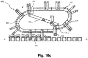
- the overhead oval track 210 is a modular conveyor 400 formed of a stepped up conveyor part 410 and a stepped down conveyor part 412 disconnected at an upper region U as well as a lower region L, adapted to be connected to each other by a step down link 414 at the upper connection region U and a step up link 416 at the lower region L thereof.
- the modular conveyor 400 includes a central lever 420 for enabling either a connecting or a disconnecting movement of the one of the step-down link 414 and / or step up link 416 simultaneously at the same time.
- the counter-movers 214 when moving longitudinally onto the modular conveyor 400, steps down from the stepped up conveyor part 410 onto the stepped down conveyor 412 through the step down link 414 as illustrated in Fig. 10a , where the step-down link 416 is first moved up to receive the counter-mover 214 thereon and then moved down to transfer the counter-means 214 onto the stepped down conveyor 414. Thereafter, the counter-means 212 is received within the package 250 while moving from the receiving end E R towards the output end E O .
- the counter-means 212 is lifted out of the secondary package 250, as illustrated in Fig. 10c , when the counter-mover 214 is moved up from the stepped down conveyor 412 towards the stepped up conveyor part 410 through the step up link 416, such that the package 250 is separated from the counter-means 212, before it is received onto the receiving conveyor 240.
- the central lever 420 in such an embodiment is adapted to provide an upward / downward movement to each of the step down link 414 and/or the step up link 416, thereby enabling the connection/disconnection of the stepped up conveyor part 410 and the stepped down conveyor 412 continuously and/or intermittently such that a continuous operation of the shaping tool 200 is achieved.
- the receiving conveyor 240 may be provided with one or more pulling means (not shown) adapted to pull the package 250 away from the counter-means 212 and receiving the secondary package 250 thereupon. Further in all such examples, the height H S of the receiving conveyor 240 is generally same as the height H F of the first conveyor 220.
- the shaping tool 200 further includes a first powering means (not shown) for enabling a movement of the one or more incoming tracks 205, the first conveyor 220, each of the parallel shaping tracks 232, the overhead conveyor 210 the receiving conveyor 240 and the slanted conveyor 245, and various sub-components thereof.
- a first powering means (not shown) for enabling a movement of the one or more incoming tracks 205, the first conveyor 220, each of the parallel shaping tracks 232, the overhead conveyor 210 the receiving conveyor 240 and the slanted conveyor 245, and various sub-components thereof.
- the first powering means is a linear servo motor adapted to move each of the one or more movers on the incoming tracks 205, the first conveyor 220, each of the parallel shaping tracks 232, the overhead conveyor 210 the receiving conveyor 240 and the slanted conveyor 245 at a first predetermined pitch facilitating a continuous operation of each of the component of the shaping tool 200 such that the incoming supply of the foldable blanks 290 is continuously formed into packages 250 of the desired shaped.
- the first powering means is a linear servo motor adapted to move each of the one or more movers on the incoming tracks 205, the first conveyor 220, each of the parallel shaping tracks 232, the overhead conveyor 210 the receiving conveyor 240 and the slanted conveyor 245 at a synchronized dynamically variable pitch facilitating a pseudo-continuous operation of each of the components of the shaping tool 200 such that the incoming supply of the foldable blanks 290 is formed into packages 250 of the desired shaped, in a pseudo-continuous and controlled operation.
- the slanted conveyor 245 is adapted to move at a second pitch, generally lesser than the first pitch, relative to the overhead conveyor 210 such that counter means 212 of the overhead conveyor 210 is freed from the package 250 while it is received onto the receiving conveyor 240.
- the shaping tool 200 includes a second powering means (not shown) for enabling a movement of each of the movers including, the counter movers 214, the clamping movers 224, the erecting movers 226, the shaping movers 234, the articulated movers 534, and the picking movers 248 independently along the corresponding tracks.
- the first powering means is linear servo motor.
- the linear motor is a generally moving magnet type of motor conventionally known in the art.
- the linear motor utilizes the corresponding conveying tracks as a stator and each of the movers as a rotor thereof.
- each of the oval tracks include an interior portion accessible through an open end.
- the oval tracks further include a plurality of coils fixedly arranged in a longitudinal direction within the interior portion thereof.
- each of the movers 214, 224, 226, 234, 248, is similar in configuration and is generally in the form of a U shaped magnetic yoke having a permanent magnet positioned there within on mutually facing inner sides thereof such that when positioned onto the corresponding tracks, each of the of the yoke forms a magnetic circuit and said stator being positioned between the permanent magnets.
- each of the counter movers 214, 224, 226, 234, 248 include a sliding mechanism such as a roller, or the like, supported by one or more roller-supporting portions formed at lower ends of the corresponding oval tracks.
- each of the movers 214, 224, 226, 234, 248 is utilized as stator whereas the oval tracks are utilized as the rotors.
- each of the movers 214, 224, 226, 234, 248 includes built in coils and each of the corresponding tracks include a plurality of magnets configured thereon in a longitudinal direction such that the movers are able to come into an electromagnetic interaction thereby enabling a movement thereof.
- the shaping tool 200 may include one or more control units (not shown) for managing the operations thereof, and particularly for managing the working of the first powering means and/or the second powering means and more particularly the movement of the shaping movers, so as to optimize the sequence of the longitudinal and/or transversal movement of the shaping lugs 233 in a predetermined and synchronized sequence.
- the predetermined sequence is particularly required to be evaluated in the instances where a specific predetermined design has to be shaped onto the one or more contact portions of the package 250.
- control unit may include an input unit for receiving the predetermined desired shape parameters of the package 250 to be formed at the shaping station 230. Further, the control unit may include a plurality of sensors (not shown) for tracking the parameters such as for example, position of the package and/or foldable blanks to be shaped, width and/or height of the packages, or the like.
- the control unit may further include a processor unit for processing the data captured by the input unit on the basis of predetermined logics/rules for facilitating the movement of the plurality of movers 214, 224, 226, 234, 248, 254.
- the control unit may further include an instruction unit that delivers the instructions to various components such as various powering means, linear motors, motors, driving units, or the like, to facilitate a desired smooth and synchronized operation.
- FIG.2 and Fig.3 schematically show the arrangement of the basic components of the shaping tool 200 of the present invention.
- secondary components such as couplers, connectors, support structure and other functional components known to one of skill in the field of shaping tools and more particularly the shaping tools for secondary package for use with conveyor systems, may be incorporated within the shaping tool 200.
- Such commercial arrangements are included in the present invention as long as the structural components and arrangements disclosed herein are present. Accordingly, it is to be contemplated that the shaping tool 200 may be configured to be used for any kind of secondary packages of any possible shape as deems possible without deviating from the scope of the current invention.
- the foldable blank generally represented by the numeral 290 is generally formed from a recyclable material selected from one or more of but not limited to any desired material such as including all kind of papers, fiberboard, corrugated board, laminated board, hybrid material, or any combinations thereof, any known housing formed by any known mechanism and suitable for use in accordance with the current disclosure without deviating from the scope thereof, may be used.
- the shape and size, including the height of the package 250 to be formed may be varied depending on the design constraints and requirements for its application. For example, within the instances when the package 250 is adapted to house twelve (beverage) containers in one layer in a 3x4 arrangement the carton is dimensioned accordingly.
- the carton may be sized and shaped to hold containers of a different or same quantity in a single layer or in more layers, and/or in different row/column arrangements (e.g., 1 ⁇ 6, 3x6, 2x6, 4x6, 2x3x4, 2x6x2, 2x9, 3x5, 3x5x2, 4x5x3, etc.).
- the packages 250 may be formed in various possible symmetrical as well as asymmetrical shapes such as tapered, oval, rhombus, and the like.
- the package 250 may be formed into any possible height in accordance to the utility and other design constraints.
- the foldable blank 290 may be made of a light weight plastic material selected from one or more of but not limited to plastic material such as group of thermoplastics including acetal, acrylic, cellulose acetate, polyethylene, polystyrene, vinyl, and nylon.
- plastic material such as group of thermoplastics including acetal, acrylic, cellulose acetate, polyethylene, polystyrene, vinyl, and nylon.
- each of the conveyors of the shaping tool 200 including the overhead oval track 210, the first conveyor 220, the shaping station 230 including each of the parallel shaping tracks 232 and the slanted conveyor 245 is generally a horizontally or vertically positioned oval track conventionally known in the art. The orientation of the oval tracks so arranged relative to each other so as to realize the functions and adjustable range of the machine within as compact a space as possible.
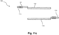
- each of the conveyors of the shaping tool 200 including the overhead oval track 210, the first conveyor 220, the shaping station 230 including each of the parallel shaping tracks 232 and the slanted conveyor 245 may be configured as a virtual closed loop conveyor as illustrated in Figs.
- the virtual closed loop conveyor 700 includes a pair of central conveying portions 710 namely 710a, 710b.
- the virtual closed loop conveyor 700 further includes a pair of shiftable conveying portions 714a, 714b, one on each side of the pair of central conveying portions 710, and adapted to move back and forth, so as to be able to connect to one of the central conveying portions 710, such that one or more movers 720 are able to smoothly move towards and away onto the corresponding central conveying portion 710 and the connected shiftable conveying portion 714a, 714b.
- Such a configuration allows a possibility to position each of the movers 720 at any desired position onto the virtual closed loop conveyor 700 without actually requiring completing an entire revolution as need to be done in conventional oval tracks.
- the shaping tool 200 is adapted to receive a continuous supply of the foldable blanks 290 which are first erected while being supported by the counter-means 212, and then formed into the corresponding packages 250 by action of the opposite lugs 233a and 233b of the shaping station 230, which are configured to push the erected foldable blanks 290 in a predetermined sequence and at each of the contact portion 251 to be shaped thereof.
- the pushing sequence is optimized for closing the one or more side flaps 294 of the foldable blank 290 using the one or more engaging mechanism and thereby forming the package 250 of the desired predetermined shape.
- Fig. 12 is a flow diagram illustrating a method 600 of forming a plurality of secondary package 250 of a predetermined desired shape, using shaping tool 200 of the present invention.
- the method starts at step 602 and proceeds to step 604 where a supply of the foldable blanks 290 is received at the first conveyor 220 and is movingly clamped between the clamping means 222 and the corresponding counter-means 212 at step 606.
- each of the plunger means 213 of the counter means clamps the bottom wall panel of the foldable blank at one of the clamping plate of the clamping means.
- step 608 the already clamped foldable blanks 290, while being conveyed onto the first conveyor 220, come in contact with either two parallel rails of the erecting means 225 such that the side panels 292, 293 of the foldable blanks 290 are gradually erected around the counter-means 212, or come into contact with a driven, foldable blank folding mechanism to fold the side panels 291 and 292 about the counter-means 212 in a short distance.
- step 610 the already erected and clamped foldable blank 290 is received between the parallel shaping tracks 232 such that one or more pairs of lugs 233, comes in contact with the contact portions 251, such that the counter-means 212 is supporting the contact portions 251 from inner side of the foldable blank 290.
- step 612 the control unit optimizes the movement of the one or more pair of lugs 234, in a longitudinal and/or a transversal direction, and in a predetermined sequence in accordance to the desired shape such that a pushing sequence is applied to the contact portions 251 of the foldable blank such that the package 250 having the predetermined desired shape at the contact portions 251 is formed.
- two pairs of lugs 233 are adapted to provide a rounding shape to the each of the four corners of the foldable blank 290.
- any number of pair of lugs 233 may be used in accordance to the shape of the package, and to provide a desired shape to the contact portions 251.
- the method 600 proceeds to step 614, where the one or more side flaps 294 is closed by engaging the engaging mechanism.
- the engagement mean is an adhesive patch, as disclosed earlier, the side flaps when pushed towards each other, folded down first on each other and thereafter, adhered under the impact of additional pushing sequence generated.
- a top open package 250 is formed having counter-means 212 placed within the inner surface thereof.
- the method then proceeds to step 614 where the each of the picking means 246 picks one of the package 250 and conveys it towards the receiving conveyor 240 to deliver the supply of package 250, each having the predetermined desired shape. Further due to a difference in pitch of the overhead conveyor 210 and the slanted conveyor 245, each of the counter-means 212 is allowed to move out of the corresponding package 250 while being conveyed towards the receiving conveyor 240 at step 616.
- each of the step of the method 600 may be performed in varied order, sequentially and/or simultaneously.
- the present invention relates to an shaping tool 200 for continuously at a constant and / or variable speed, and / or intermittently forming a plurality of packages 250 having a predetermined shape at the one or more contact portions thereof, for holding a plurality of objects or items, such as e.g. beverage containers generally containing liquids, such as beer, wine, cider, hard liquor (e.g., distilled beverage, spirit, liquor, hard alcohol, etc.), soft drinks (e.g., cola, soda, pop, tonic, seltzer), iced tea, soda water and other types of carbonated/non-carbonated beverages.
- a plurality of objects or items such as e.g. beverage containers generally containing liquids, such as beer, wine, cider, hard liquor (e.g., distilled beverage, spirit, liquor, hard alcohol, etc.), soft drinks (e.g., cola, soda, pop, tonic, seltzer), iced tea, soda water and other types of carbonated/non-carbonated beverages.
- the current disclosure is additional advantageous in maintaining the strength of the sidewall of the secondary package 250 due to the fact that, the counter-means 212, the clamping plates 222, and the shaping lugs 233, shaped in accordance with the predetermined shape to be achieved and therefore, a specific pushing sequence is employed at the specific contact portions 251, which are being supported specifically at the inner side thereof.
- a specific pushing sequence is employed at the specific contact portions 251, which are being supported specifically at the inner side thereof.
- the movement is optimized such that while the tool 200 shapes the contact portions 251 of the secondary package 250, the impact is not too high that it damages the walls/contact portions 251 of the package 250 and also avoids/resist any movement or misalignment of the items, e.g. beverage containers, stored there within, with respect to the package 250.
- the items e.g. beverage containers
- the shaping tool is adaptable to different dimensions of foldable blank and is therefore well suitable to process the packages of different sizes with ease and efficiently.
- the predetermined shape may be changed by simply changing the lugs 233, and therefore not requiring changing the entire apparatus for different predetermined shapes.
- the present invention provides the possibility of manufacturing the conveyor system with integrally formed shaping tools.
- Such a conveyor system for shaping secondary package having predetermined shape while being cost-efficient, is very quick and easy to use and offers comfortable handling of packages of any shape, size or any variety of configurations.
- shaping tool 200 of the current disclosure while being applicable onto the conveyor system, does not impact the rest of the conveying process.
- a single conveyor system may utilize as many as shaping tools within the same arrangement. Further, in case of one shaping tool is not working, rest can keep working and therefore, the fault tolerance of the plant can be increased.
- the package 250 of the current disclosure may be implemented in various industries such as food industry, transport industry, house hold appliance industry in transportation of any kind of product or group of products, of any shape, size or any variety of configurations, without limiting it to the beverage industry.
- the package 250 formed of foldable blanks may be used to shape all currently known packages, known in the art including various packages formed from foldable blanks as well as packages constructed of materials such as thermoplastic, hybrid materials, woven metallic fabric that may include ferrous or nonferrous metals, etc., or any other suitable material.
Abstract
A shaping tool (100) for shaping a package formed of a foldable blank, comprising an overhead oval track (110) comprising a plurality of downwardly protruding spaced apart counter-means (112), a first conveyor (120) extending between a receiving end towards an output end, and adapted to receive the foldable blank and/or a package from an incoming conveying line at the receiving end, a shaping station (130) extending away from the receiving end, the shaping station comprising a pair of parallel shaping tracks (132), each positioned on one side of the first conveyor, the pair of generally parallel shaping tracks comprising a plurality of pairs of independently movable shaping lugs (134), each pair of shaping lugs having a predetermined shape and adapted to receive one of the foldable blanks there-between; the pair of lugs movable towards each other to form a package having a desired shape.
Description
- The present invention relates generally to the formation of packages; and more particularly relates to a shaping tool for forming packages having a predetermined shape.
- In the recent years, there has been a many-fold increase in the packaging trend for primary as well as secondary packaging, e.g. for the purpose of grouping a number of items such as food items, including liquid foods, home essentials, stationary items, beverage containers, and the like, for various purposes such as to enable bulk selling, easy transportation, handling, and the like.
- There has been a considerable increase in the use of folding box-based packages for holding a plurality of items or objects, and therefore the number of boxes that are manufactured is increasing. Further, due to marketing, and for utility purposes, these boxes are prepared in a variety of shapes and sizes.
- These packages are generally formed from foldable blanks, commonly die cut from large sheets or rolls. The sheets or rolls may be printed, embossed, coated, and die cut in a continuous process at the packaging material supplier, of which die cutting is the final step. Thereafter, these foldable blanks are folded at the product producer using one or more folding mechanisms to obtain the package of the desired shape.
- Numerous folding mechanisms have been proposed for shaping these precut blanks. In some instances, these foldable blanks are scored, and provided with fold-lines & cut-outs to form wall corner portions and joining portions at the ends of corresponding first wall forming portions. In operation, the wall forming portions are erected and the corner portions are bent to connect the joining portion to form a folding box package. One such technique is disclosed within
US patent number 3841476 , disclosing the use of a pre-cut blank of cardboard or like material to form a tray shaped package. The blank is scored and provided with cut-outs to form wall corner portions and uniting portions at the ends of corresponding first wall forming portions and also to form strengthening tabs. The tray is formed by first erecting the strengthening tabs and by then erecting the first and second wall forming portions and finally bending the corner portions and uniting portions so that the latter can be secured to the second wall forming portions. However, the use of scoring/folding line techniques shows the typical limitation of the folding machinery being package specific and being suitable only for the typically rectangular shape of package in a limited range of sizes and material thicknesses. Further, the method is suitable generally for packages requiring straight folds and not for packages with innovative designs including miters, curves, and rounded sides and/or corners. - Other folding tools, e.g. pivotally mounted on conveyors, have been provided in the art. These tools include molds within which a moving foldable blank is received and pushed by a means of an ascending/descending core to form a package similar to the shape of mold.
- In some other instances, a package of a predetermined shape is obtained by placing the foldable blank between plurality of molds and thereafter the sheet is pushed against the mold such that a box of shape corresponding to the mold is formed. One such mold based shaping mechanism is disclosed within
WO2017174347A1 which discloses a device for molding a closed packaging comprising the following: a base for supporting the bottom of the packaging and at least two support elements for supporting the lateral surfaces and at least two sliding elements for molding the lateral surfaces of the packaging. The support elements and the sliding elements have at least one molding surface on the element face paired with the packaging. The aim of the invention is to allow a precise molding of the packaging even for closed packaging with a complex geometry. - However, such mold based shaping of packages is not preferred in case of e.g. industrial applications requiring a large range of sizes and shapes, necessitating the use of several molds in accordance with the range; this mold-based method therefore poses quite some challenges in terms of efficiency, cost and capability to shape various complex packages.
- Accordingly, as can be understood from the foregoing discussion, none of the existing solutions completely overcomes the problem of using a single shaping tool for shaping packages of varying sizes and design. Thus, in the context of the above, an improved shaping tool is desired, which being cost effective and easy to implement allows to carry out the shaping of packages of a wide range of size, shape, material and functional design features, without requiring pack specific interchanging elements and components.
- In an aspect of the invention, a shaping tool for forming a package is provided. Said package may have one or more contact portions of a predetermined shape, and formed of a foldable blank having a bottom panel extended towards a first side panel in one direction and a second side panel in a direction opposite to the first direction, is provided. The shaping tool includes an overhead oval track having a plurality of downwardly protruding spaced apart counter-means configured thereon. The shaping tool further includes a first conveyer extending between a receiving end towards an output end and adapted to receive foldable blanks from an incoming conveying line. The first conveyor includes a plurality of clamping means, each configured to be positioned below one of the downwardly protruding counter-means and adapted to clamp a foldable blank there between. The first conveyor further includes an erecting means for erecting each of the already clamped foldable blanks, while moving on the said first conveyor from the receiving end towards the output end.
- The shaping tool furthermore includes a shaping station extending away from the erecting means towards the output end and having a pair of parallel shaping tracks, each track positioned on a different side parallel to the first conveyor. Each of the shaping tracks includes a plurality of independently movable lugs configured in pairs, wherein a first lug within a pair of lugs is attached to a first parallel shaping tracks and a second lug within said pair of lugs is attached to the second parallel shaping track, and adapted to support the carton/package there-between the shaping tracks. Each of the pair of lugs has a predetermined shape in accordance to a desired shape of the package. In operation, each of the foldable blank received at the receiving end of the first conveyor is first clamped by the clamping means, erected by the erecting means and then shaped into a carton of the desired shape at the shaping station, while being conveyed towards the output end.
- Potentially, the clamping means includes one or more clamping plates adapted to clamp the bottom wall panel of the foldable blank below one of the counter-means.
- Further potentially, the erecting means includes either a pair of parallel sloping rails, each configured onto one side of the first conveyor such that the side panels of each of the clamped foldable blank gets erected around the corresponding counter means, while being conveyed towards the output end, or an actuated folding mechanism (not shown) configured to fold the side panels, 291 and 292, of the foldable blank within a short distance of first conveyor movement, without imposing any torque or moment on the location and alignment of the foldable blank 290 and causing the side panels of the blank to fold at the score line by application of evenly distributed forces across the lengths of the side panels being folded.
- Possibly, the pair of shaping tracks in the shaping station include a transversal moving mechanism for enabling a transversal and/or pivotal movement of one or more pair of shaping lugs.
- Further possibly, the said transversal moving mechanism includes an extension means configured onto each of the pair of movable lugs for moving the lugs transversally towards and away from each other.
- Generally, the shaping tool includes a receiving conveyor configured at the output end, at a height lower than the first conveyor, and adapted to receive the supply of the carton of desired shape.
- Potentially, the shaping tool further includes a generally slanted conveyor configured at a height above the first conveyor but lower than the overhead track, and extending towards the receiving conveyor.
- Further potentially, the slanted conveyor includes a plurality of picking means, each adapted to pick up one of the shaped package from the first conveyor and deliver towards the receiving conveyor.
- Alternatively, the slanted conveyer may be a generally horizontally tilted conveyor belt adapted to pull away each of the shaped secondary package frictionally away from the corresponding counter-means.
- Additionally, the incoming conveying line includes one or more incoming oval tracks adapted to deliver the supply of foldable blanks to the receiving end of the first conveyor.
- Preferably, the one or more incoming tracks, the first conveyor, each of the parallel the shaping tracks, the overhead conveyor and the slanted conveyor are adapted to continuously move at a predetermined pitch so as to convert the supply of foldable blanks into cartons of the desired shaped continuously.
- Further preferably, the slanted conveyor is adapted to move at a pitch relative to the overhead conveyor such that counter means of the overhead is freed from the shaped secondary package while it is received onto the receiving conveyor.
- Alternatively, the one or more incoming tracks, the first conveyor, each of the parallel shaping tracks, the overhead conveyor and the slanted conveyor are adapted to move intermittently at a variable pitch as required, so as to convert the supply of foldable blanks into cartons/packages of the desired shaped intermittently.
- Potentially, the shaping tool includes a first powering means for enabling a movement of the one or more incoming tracks, the first conveyor, each of the parallel shaping tracks, the overhead conveyor and the slanted conveyor.
- Possibly, the first powering means is a linear servo motor utilizing the corresponding tracks as stator and each of the corresponding movers as a rotor.
- Alternatively, the powering means may be selected from one or more of but not limited to various conventionally known controllable, actuators, servo drives, independent cart or mover technologies and the like, conventionally known in the art.
- Additionally, the shaping tool includes a plurality of movers movingly configured onto each of the first conveyor, the parallel shaping tracks, the overhead conveyor, and the slanted conveyor, each of the movers adapted to movingly engage the corresponding clamping means, the movable lugs, the counter-means and the picking means respectively.
- Further, each of the plurality of movers is individually powered by a second powering means, preferably a linear motor, utilizing each of the movers as a rotor thereof and the corresponding track as a stator thereof.
- The counter means may be a plunger means having a shape enabling the formation of the predetermined desired shape of the carton and adapted to support the package formation from inside the package while shaping the contact portions of the erected carton.
- The foldable blank may be of a material selected from one or more of but not limited to a carton, paperboard, thermoplastic, hybrid material, and the like.
- Furthermore, he foldable blank may include one or more side flaps configured onto at least one of the side panels, and further including one or more engaging mechanisms for closing the side flaps.
- Yet further possibly, the said engaging mechanism may be selected from one or more of but not limited to a gluing layer, locking cut-outs, and the like.
- Particularly, the contact portion is selected from one or more of but not limited to a side and/or corner and/or edges of the package.
- Possibly, the shaping tool further includes a control unit for optimizing the movement of the one or more incoming tracks, the first conveyor, each of the parallel shaping tracks, the overhead conveyor and the slanted conveyor.
- Further possibly, the control unit is adapted to optimize the synchronized movement of the plurality of movers so as to longitudinally move the corresponding clamping means and/or the corresponding counter means and/or the corresponding shaping lugs and/or the corresponding picking means independently and relative to each other.
- Yet further possibly, the control unit includes one or more sensors, one or more input unit, a processor unit and an output unit.
- In yet another aspect of the invention, a method of forming a package of a predetermined shape from a foldable blank using the shaping tool of current disclosure, is provided. The method includes receiving one or more foldable blanks at the receiving end of the first conveyor, each of the foldable blanks having a bottom panel extended towards a first side panel in first direction and a second side panel in a second direction opposite to the first direction.
- The method further includes clamping the received foldable blank between one of the clamping means and a corresponding counter means. The method furthermore includes erecting the first side panel and the second side panel around the counter means while moving the clamped foldable blank towards the output end onto the first conveyor. The method furthermore includes receiving the clamped erected foldable blank at the shaping station between one or more pair of lugs, and optimizing the movement of the pairs of lugs longitudinally and transversally to apply a predetermined pushing sequence onto one or more contact portions of the erected foldable blank, thereby closing the side panels and forming a package having a predetermined shape.
- Additionally, the method includes picking the already shaped secondary package from the first conveyor using one of the picking means and delivering to the receiving conveyor.
- Particularly, each of the one or more pair of shaping lugs are moved together in a predetermined sequence of transversal movement and/or longitudinal movement and/or pivotal movement, so as to push and in turn shape the one or more contact portions of the erected blank.
- Furthermore, the method includes optimizing the pushing, pulling, holding sequence of the side flaps to align and engage them together and thereby closing the side flaps of the carton and in a consistently manner repeatedly achieve the desired dimensions, shape and flap alignment of the pack.
- Possibly, the automated pushing or pulling or holding sequence is determined by the control unit on the basis of an automation recipe, an input from a user and/or inputs from one or more sensors.
- The details of one or more implementations are set forth in the accompanying drawings and the description below. Other aspects, features and advantages of the subject matter disclosed herein will be apparent from the description, the drawings, and the claims.
-
-
FIG. 1 illustrates a schematic diagram representing a shaping tool, in accordance with a preferred embodiment of the present invention; -
FIG. 2a illustrates a front view diagram representing an exemplary shaping tool for formation of packages having predetermined shape, in accordance with a preferred embodiment of the present invention; -
FIG. 2b illustrates an exemplary foldable blank, in accordance with a preferred embodiment of the present invention; -
FIG. 3 illustrates a perspective view diagram representing an exemplary shaping tool for formation of packages having predetermined shape, in accordance with the preferred embodiment of the present invention; -
FIG. 4 illustrates a schematic diagram representing a shaping station of the shaping tool, in accordance with a preferred embodiment of the present invention; -
FIG. 5 illustrates an exemplary shaping operation, in accordance with the preferred embodiment of the present invention; -
FIG. 6 illustrates an exemplary erecting means, in accordance with the preferred embodiment of the present invention; -
FIG. 7a ,7b and7c illustrates exemplary clamping means along with exemplary counter means, in accordance with the various embodiments of the present invention; -
FIG. 8 illustrates an exemplary mover, in accordance with the preferred embodiment of the present invention; -
FIG. 9 illustrates an exemplary an articulated movement assembly assembly, in accordance with the preferred embodiment of the present invention; -
FIG. 10a illustrates an exemplary overhead conveyor, in accordance with an exemplary embodiment of the present invention; -
FIG. 10b and10c illustrates another exemplary overhead conveyor, in accordance with another exemplary embodiment of the present invention; -
FIG. 11a and11b illustrates a virtual close loop conveyor, in accordance with an exemplary embodiment of the present invention; -
FIG. 11c illustrates a top view of the virtual close loop conveyor, in accordance with an exemplary embodiment of the present invention; - It is to be understood that the enclosed embodiments are merely exemplary of the present invention, which may be embodied in various and/or alternative forms. Specific structural and functional details disclosed herein are not to be interpreted as limiting, but merely as a basis for the claims and as a representative basis for teaching one skilled in the art to variously employ the present invention in virtually any appropriately detailed structure.
- Aspects, advantages and/or other features of the exemplary embodiments of the present disclosure will become apparent in view of the following detailed description. In describing exemplary embodiments, specific terminology is employed for the sake of clarity. However, the embodiments are not intended to be limited to this specific terminology. It is to be understood that each specific portion includes all technical equivalents that operate in a similar manner to accomplish a similar purpose.
- Exemplary embodiments may be adapted for many different purposes and are not intended to be limited to the specific exemplary purposes set forth herein. Those skilled in the art would be able to adapt the exemplary-only embodiments of the present invention, depending for example, on the intended use.
- The present application discloses a shaping tool, for forming a package of a desired shape. It is to be understood that the said package may be a primary or a secondary package, the said secondary package adapted to hold e.g. a plurality of items or objects such as e.g. food items, including containers of liquid foods or beverages, home essentials, stationary items, and the like. An efficiency of the shaping tool is the ability to form packages of a predetermined shape in various sizes without requiring major changes in the functional elements thereof. Further, the predetermined shapes may be varied by changing only one shaping component of the tool, without requiring significant change of the entire apparatus. While the package of the current disclosure is exemplified as a generally box shaped container formed of a foldable blank, it should be understood that the embodiments of the present invention may be applied in combination with various type of design and utilities irrespective of size, shape and materials. It must also be noted that, as used in this specification and the appended claims, the singular forms "a," "an" and "the" include plural referents unless the context clearly dictates otherwise. Thus, for example, the term "an opening" is intended to mean a single opening or a combination of openings, "a sidewall" is intended to mean one or more sidewalls, or a combination thereof.
- As illustrated in
FIG. 1 , the present invention provides ashaping tool 100 for forming apackage 150 of a predetermined shape, from a foldable blank 190 having abottom panel 191 extended towards afirst side panel 192 in one direction and asecond side panel 193 in a second direction. Saidfoldable blanks 190 are continuously supplied from an incoming line 105 and shaped by employing ashaping tool 100 for shaping one or more contact portions of thesecondary package 150. Theshaping tool 100 includes an overheadoval conveyor 110 having a plurality of generally downwardly protruding (perpendicular to the track) spaced apart counter-means 112 configured thereon, when considering the lower portion of the oval track. Theshaping tool 100 further includes afirst conveyer 120 positioned below theoverhead conveyor 110, extending between a receiving end ER towards an output end EO and adapted to receive a supply offoldable blanks 190 from an incoming conveying line 105. The incoming conveying line 105 is generally a conveying apparatus and in preferred embodiment includes two generally parallel oval tracks 105a, 105b. Thefirst conveyor 120 includes a plurality of clamping means 122, each configured to be positioned below one of the downwardly protrudingcounter-means 112 and adapted to clamp one of the foldable blank 190 there between. Thefirst conveyor 120 further includes an erecting means (not shown) for erecting each of the foldable blank 190 received onto the clamping means 122 while moving onto thefirst conveyor 120 from the receiving end ER towards the output end EO . - The
shaping tool 100 further includes a shapingstation 130 having a pair of parallel shaping tracks 132, each positioned on a different side parallel to thefirst conveyor 120 and extending away from the erecting means (not shown) towards the output end EO . The parallel shaping tracks 132 include a plurality of pair of independently movable shaping lugs 134, adapted to support the erected foldable blank 190 there-between the shaping tracks 132. Each of the pair oflugs 134 is formed into a predetermined shape enabling the formation of the predetermined desired shape of thepackage 150. The shapingstation 130 further includes a transversal movement mechanism 136 for moving the pair oflugs 134 towards and away from each other. In operation, each of thefoldable blanks 190 received at the receiving end ER of thefirst conveyor 120 is first clamped by the clamping means 122, then erected by the erecting means (not shown) and then shaped to form into thepackage 150 of the desired shape at the shapingstation 130, while being conveyed from the receiving end ER of thefirst conveyor 120 towards the output end EO of thefirst conveyor 120. - In a preferred embodiment, as illustrated in
Fig. 2a , an exemplarypackage forming system 280 having an incoming conveyingline 205 carrying a continuous supply offoldable blanks 290 and employing a shaping tool 200 for shaping one or more contact portions of thesecondary package 250, to be formed is provided. The conveyingline 205 is generally a conveying apparatus and in preferred embodiment includes two generally paralleloval tracks Fig. 3 , together adapted to facilitate a movement of a supply offoldable blanks 290 towards the shaping tool 200 of the current disclosure. - In a preferred embodiment, as illustrated in
Fig. 2b the foldable blank 290 includes abottom wall panel 291 extended between afirst side panel 292 at a first end EF and asecond side panel 293 at a second end ES . Theside panels bottom wall panel 291, to form thepackage 250 defining an inner surface (not shown) there within. Further, the at least one of the one ormore side panels side panels package 250 from the sides. The engaging mechanism may be selected from one or more of but not limited to notch based fixation mechanism, gluing, adhesive patches, retention tab, rivets, and any other suitable engaging mechanisms particularly which can be closed by using a pushing, latching or combination of push pull sequence, conventionally known in the art and suitable for use in current invention, without deviating from the scope thereof. - As disclosed earlier and shown in
Fig. 2a ,, the shaping tool 200 includes anoverhead conveyor 210 generally in the form of an oval track, having a plurality of spaced apart counter-means 212 configured perpendicular to the track thereon and hence generally downwardly protruding when considering the lower portion of the track. The counter-means 212 is generally a support body adapted to support the foldable blank 290 during formation and during the shaping operation of thepackage 250 to be formed. Each of thecounter-means 212 is movingly connected to theoverhead track 210 through one or morecounter movers 214 and each counter-means 212 may include one or more plunger means 213 Alternatively, thecounter-means 212 may include any suitable mechanism conventionally known in the art for facilitating such an independent longitudinal movement across theoverhead track 210. The one or more plunger means 213 may be a single plunger body to support thepackage 250 or otherwise may be a combination of a plurality of individual plunger bodies, arranged in a predetermined group configuration to support thepackage 250 during shaping operation. In some embodiments of the present invention, the one or more plunger means 213 may be replaced with any shaping body suitable for supporting the foldable blank 290 and thecorresponding package 250 as disclosed above. - The shaping tool 200 further includes a
first conveyer 220 adapted to receive the supply of thefoldable blanks 290 from the incoming conveyingline 205. Thefirst conveyor 220 is generally positioned below theoverhead track 210 and extending between a receiving end ER towards an output end EO . - The
first conveyor 220 includes a plurality of clamping means 222, each configured to be positioned below one of the downwardly protrudingcounter-means 212 and adapted to clamp one of the foldable blank 290 there between. - In a preferred embodiment, the clamping means 222 includes one
more clamping plates 223, as shown inFig 7a ,7b ,7c , movingly configured onto thefirst conveyor 220 and positioned to receive thebottom wall panel 291 of the foldable blank 190 thereupon. Further, the one ormore clamping plates 223 are adapted to meet one of the counter means 212 while being conveyed onto thefirst conveyor 220 such that the one ormore clamping plates 223 and the corresponding counter means 212 facilitates a clamping of thebottom wall panel 291 there-between at a point of contact C (Fig. 2a ). In some embodiments, the clamping means 222 further includes one or more clampingmovers 224 adapted to movingly engage the one ormore clamping plates 223 onto thefirst conveyor 220 thereby enabling an independent movement of each of the one ormore clamping plates 223 onto thefirst conveyor 220. Alternatively, the clamping means 222 may include any suitable mechanism conventionally known in the art for facilitating such an independent longitudinal movement of the one ormore clamping plates 223 onto thefirst conveyor 220. - In some embodiments, the clamping means 222 may additionally be adapted to centrally position the
foldable blanks 290 onto thefirst conveyor 220. In one such instances, the clamping means 222 includes one or more pin structures (not shown) and corresponding pin holes within thecounter-means 212. Further, thefoldable blanks 290, in such instances, also includes one or more holes, or combination of hole and slots, configured at a center portion thereof, such that when received onto thefirst conveyor 222, the foldable blank 290 is supported centrally by the connection between the pin of the clamping means 222 and the pin-holes of thecounter-means 212 through the center holes, or combination of hole and slots, of the foldable blank 290. Alternatively, in other instances, thecounter-means 212 includes one or more pin structure (not shown) and corresponding pin holes within the clamping means 222, such that when received onto thefirst conveyor 222, the foldable blank 290 is supported centrally by the connection between the pin of thecounter-means 212 and the pin-holes of the clamping means 222 through the center holes, or combination of hole and slots or shape feature, of the foldable blank 290. Alternatively, in other embodiments, shaping tool 200 may include any suitable centering mechanisms conventionally known in the art. - In a preferred embodiment of the present invention as illustrated in
Fig. 7a ,7b and7c , the number of clampingplates 223 is generally equal to a number of rows of the plunger means 213 such that each of the plunger means 213 within the same row is supported by one of the clamping plates. Further, the number of clampingplates 223, and the number of rows of plunger means 213, are optimized in accordance to thecontact portions 251 to be shaped. In a preferred embodiment, the clamping means 222 include two clampingplates 223 for supporting a counter-means 212 having a plurality of plunger means 213, arranged in two rows. - The
first conveyor 220 further includes an erectingmeans 225 for erecting each of thefoldable blanks 290 received onto the clamping means 122 and clamped there-between the one ormore clamping plates 223 and thecorresponding counter-means 212, while being conveyed through thefirst conveyor 220 from the receiving end ER towards the output end EO . In a preferred embodiment of the present invention, the erecting means 225 may include two parallel erecting rails, as illustrated inFig. 6 , and/or an articulated or compact folding mechanism, each positioned onto a different side of thefirst conveyor 220 and extending away from the point of contact C towards the output end EO in a generally vertically slanted configuration such that the each of theside panels counter-means 212 while being conveyed onto thefirst conveyor 220 from the receiving end ER towards the output end EO . In an embodiment of the present invention, each of the two or more erecting rails of the erecting means 225 is movingly connected to thefirst conveyor 220 using one or more erectingmovers 226. Alternatively, the two or more erecting rails of the erecting means 225 are positioned, one on each side of thefirst conveyor 220 using any positioning mechanisms such as a manipulator, robotic arm, and the like. Yet alternatively, the positioning mechanism may include any conventionally known manual manipulation mechanism. - The shaping tool 200 further includes a shaping
station 230 extending away from the erecting means 225 towards the output end EO of thefirst conveyor 220. The shapingstation 230 is generally adapted to receive the already erected foldable blank 290 and convert it into thepackage 250 having the desired shape at the one ormore contact portions 251. As illustrated inFig. 4 , the shapingstation 230 includes a pair of parallel shaping tracks 232, namely 232a and 232b, each positioned on a different side and generally parallel to thefirst conveyor 220 and extending away from the erecting means 225 towards the output end EO . The generally parallel shaping tracks 232 include a plurality of pairs of independently movable shaping lugs 233 adapted to support the already erected foldable blank 290 including thecorresponding counter-means 212 there-between the shaping tracks 232. - Each of the pair of shaping lugs 233 is formed into a predetermined shape in accordance to a desired shape to be configured onto the one or more contact portions of the
secondary package 250 to be formed. Accordingly, the predetermined shape of each of the shaping lugs 233 is of a shape complementary to the desired shape that needs to be provided to the contact portion of thepackage 250. For example, in a preferred embodiment, the desired shape is a cuboidalshaped package 250 with generally rounded corners. In such an embodiment, the shape oflugs 233 is generally arc shaped and thecontact portion 251 is the portion of the foldable blank 290 corresponding to the corners thereof. In such an embodiment, two pairs of themovable lugs 233 are adapted to be utilized for forming and shaping asingle package 250. However, in other embodiments, any number of pair of movable shaping lugs 233 may be utilized in accordance to the shape of thepackage 250 to be formed, thecontact portions 251 to be shaped, and the desired shape. - In a preferred embodiment, the plurality of pair of
lugs 233 includes afirst lug 233a, and asecond lug 233b are movably connected to theparallel shaping tracks movers 234 and is adapted to receive the foldable blank 290 along with thecorresponding counter-means 212 there-between. Further, each of the plurality of shapingmovers 233 is movingly connected to one of the shaping tracks 232 such that an independent longitudinal movement of each of thelugs 233 along the corresponding shaping tracks 232 is made possible. Such an independent movement of the shapingmovers 234 allows possibility of forming and in turn shaping thepackages 250 into asymmetrical shaped packages. - The shaping
station 230 further includes a transversal and/orpivotal moving mechanism 235 for facilitating a transversal and/or pivotal movement of each of thefirst shaping lug 233a, and asecond shaping lug 233b towards and away from each other (Fig. 5 ). In the preferred embodiment as disclosed above, the transversal movingmechanism 235 includes an extension means adapted to be positioned between each of themovers 234 and the corresponding shapinglug 233 and enables an movement of each lug of the pair oflugs 233 in a direction towards and away from each other. - In a preferred embodiment, , the extension means may include an articulated
movement assembly 500 as illustrated inFig. 9 . In such an embodiment, each of the pair of shapinglugs movers 234, pivotally and movably attached to each other through one or more articulated mountingbrackets 502. The articulatedbracket 502 is a conventionally known mounting bracket having a first attachment bracket 503 connected to a second attachment bracket 504 at their distal ends such that the articulatedbracket 502 has three open ends, i.e. a firstopen end 503a at a proximal end of the first attachment bracket 503, a secondopen end 504a at the proximal end of the second attachment bracket 504 and a pivotallymovable center end 505 . - As illustrated in
Fig. 9 , the articulatedmovement assembly 500 includes a first articulatedmover 534a connected to a second articulatedmover 534b through the articulated mountingbrackets 502, each of themovers bracket 502, such that the articulatedbracket 502 is pivotally movable in a generally transversal plane throughout the longitudinal range of motion of the first articulatedmover 534a and the articulatedsecond movers 534b, towards and/or away from each other. The articulatedassembly 500 is connected to the shapinglug 233 at the pivotallymovable center end 505 thereof. - In a collapsed position, where the articulated mounting
bracket 500 is closed, such that each of the pair of pivotally connected articulatedmovers lug 233 is at its initial position. In an opened position, where the articulated mountingbracket 500 opens up pivotally, the pair of the articulatedmovers corresponding shaping lug 233a is moved transversally/pivotally towards/away from the opposite shaping lugs 233b. - It is to be contemplated that the one skilled in the art will recognize that the articulated
movement assembly 500 having the pair of articulatedmovers movement assembly 500 is movingly supported on to the shaping tracks 232 such that a horizontal movement of themovers movers assembly 500 and therefore enables the movement of the mounting bracket between 502 its collapsed position and its open position, thereby enabling a range of transversal/pivotal extension along with an longitudinal movement of the shaping lugs 233 onto thecorresponding shaping track 232. Further, it is to be contemplated that the articulated movers 534 are same as the shapingmovers 234 disclosed across the current disclosure. - Therefore, by appropriate manipulation of the first articulated
mover 534a, the second articulatedmover 534b, and therefore the articulatedassembly 500, the shapinglug 233 can be positioned at any desired distance away from the shaping tracks 232, while moving the shapinglug 233 in an operative orientation generally in a transversal and/or horizontal direction. - In yet other embodiments, the extension means may be selected from any suitable conventionally known extension mechanism already known in the art.
- In some embodiments of the present invention, loaded products and counter-means which fill the voids between the neck areas of the primary packaging and the contact zones of the foldable blanks are used in the package formation. In this case, the
first conveyor 220 is adapted to receive already formedpackages 250, and pre-loaded with beverage containers (not shown) such as bottles, or the like, in a predetermined arrangement, so as to support thepackage 250 from inside and in accordance to the desired shape. In such embodiments, thecounter-means 212 includes a plurality of plunger means 213 having a shaping body configured to be received onto a neck portion of each of the beverage containers. Further, in such embodiments, the shaping tool 200 does not require clamping means 222 and erectingmeans 225 since an already formed package is received at thefirst conveyor 220. Additionally, in such embodiments, the shapingstation 230 receives the already formedpackage 250 and shapes thecontact portions 251 thereof in accordance to the desired shape. - In some embodiments of the current disclosure, the shaping tool 200 includes a receiving
conveyor 240 adapted to receive the supply ofsecondary package 250 already formed and shaped from the supply of foldable blank 290, in accordance to the predetermined shape from thefirst conveyor 220. The receivingconveyor 240 is generally an outgoing oval track positioned at a height HC lower than a height HF of thefirst conveyor 220 and extends away from its output end EO . - Further in such embodiments, the shaping tool 200 may furthermore include a generally slanted
overhead conveyor 245 positioned at a height HS generally higher than the height HF of thefirst conveyor 220. The slantedconveyor 245 is adapted to pick up the already formedpackages 250 from thefirst conveyor 220 and deliver towards the receivingconveyor 240. The slantedconveyor 245 includes a plurality of spaced apart picking means 246, each adapted to pick up one of the shapedpackage 250 from thefirst conveyor 220. The picking means 246 includes a generally, hook shapedpickers body 247 adapted to hook up thepackage 250 at one or more portion selected from but not limited to handle, flaps, and the like. In some embodiments of the present invention, each of the picking means 246 further include apicking mover 248 adapted to movingly connect thepicker body 247, downwardly onto the slantedconveyor 245. Alternatively, the picking means 246 may include any suitable mechanism conventionally known in the art for facilitating such an independent longitudinal movement of the pickingbody 247 longitudinally across the overhead slantedconveyor 245. In some embodiments of the present invention the picking means 246 may be any suitable mechanism conventionally known in the art. - In some other embodiments, slanted
overhead conveyor 245 may be a generally horizontally tilted conveyor belt (not shown) adapted to pull away each of thepackages 250 frictionally away from the corresponding counter-means 212 and deliver towards the receivingconveyor 240. In yet other embodiments, the slantedoverhead conveyor 245 may be formed in any suitable configuration so as to receive thepackages 250 from thefirst conveyor 220 and deliver it towards the receivingconveyor 240. - Alternatively, in some embodiments, the shaping tool 200 may not require slanted
overhead conveyors 245 for delivering thepackage 250 towards the receivingconveyor 240. In such embodiments, in some instances, the overheadoval track 210 may be adapted to lift up thecounter-means 212 and/or push down thepackages 250 away from thecounter-means 212 such that thepackage 250 is separated from thecounter-means 212 before it is received onto the receivingconveyor 240. For example, as illustrated inFig. 10a , the overheadoval track 210 having a generally slanted upside S towards the output end EO is provided. Further, thecounter-means 212 are mounted at a fixed predetermined angle relative to thecounter movers 214 such that thecounter-means 212 vertically moves out of thepackage 250 when travelling upwardly at the slanted up side S of theconveyor 210, and therefore, thepackage 250 is conveniently received at the receivingconveyor 240. Thecounter-means 212, in such embodiments may include mounting means M for maintaining the fixed predetermined angle between thecounter mover 214 and the counter-means 212. - In another example, as illustrated in
Fig, 10b and10c , the overheadoval track 210 is amodular conveyor 400 formed of a stepped upconveyor part 410 and a stepped downconveyor part 412 disconnected at an upper region U as well as a lower region L, adapted to be connected to each other by a step down link 414 at the upper connection region U and a step uplink 416 at the lower region L thereof. - Further, the
modular conveyor 400 includes acentral lever 420 for enabling either a connecting or a disconnecting movement of the one of the step-down link 414 and / or step uplink 416 simultaneously at the same time. - In operation, the
counter-movers 214 when moving longitudinally onto themodular conveyor 400, steps down from the stepped upconveyor part 410 onto the stepped downconveyor 412 through the step downlink 414 as illustrated inFig. 10a , where the step-down link 416 is first moved up to receive the counter-mover 214 thereon and then moved down to transfer thecounter-means 214 onto the stepped downconveyor 414. Thereafter, thecounter-means 212 is received within thepackage 250 while moving from the receiving end ER towards the output end EO . - Further, the
counter-means 212 is lifted out of thesecondary package 250, as illustrated inFig. 10c , when the counter-mover 214 is moved up from the stepped downconveyor 412 towards the stepped upconveyor part 410 through the step uplink 416, such that thepackage 250 is separated from thecounter-means 212, before it is received onto the receivingconveyor 240. Thecentral lever 420 in such an embodiment is adapted to provide an upward / downward movement to each of the step downlink 414 and/or the step uplink 416, thereby enabling the connection/disconnection of the stepped upconveyor part 410 and the stepped downconveyor 412 continuously and/or intermittently such that a continuous operation of the shaping tool 200 is achieved. - In yet other examples, the receiving
conveyor 240 may be provided with one or more pulling means (not shown) adapted to pull thepackage 250 away from thecounter-means 212 and receiving thesecondary package 250 thereupon. Further in all such examples, the height HS of the receivingconveyor 240 is generally same as the height HF of thefirst conveyor 220. - The shaping tool 200 further includes a first powering means (not shown) for enabling a movement of the one or more
incoming tracks 205, thefirst conveyor 220, each of the parallel shaping tracks 232, theoverhead conveyor 210 the receivingconveyor 240 and the slantedconveyor 245, and various sub-components thereof. In a preferred embodiment, the first powering means is a linear servo motor adapted to move each of the one or more movers on theincoming tracks 205, thefirst conveyor 220, each of the parallel shaping tracks 232, theoverhead conveyor 210 the receivingconveyor 240 and the slantedconveyor 245 at a first predetermined pitch facilitating a continuous operation of each of the component of the shaping tool 200 such that the incoming supply of thefoldable blanks 290 is continuously formed intopackages 250 of the desired shaped. However, in other embodiments, the first powering means is a linear servo motor adapted to move each of the one or more movers on theincoming tracks 205, thefirst conveyor 220, each of the parallel shaping tracks 232, theoverhead conveyor 210 the receivingconveyor 240 and the slantedconveyor 245 at a synchronized dynamically variable pitch facilitating a pseudo-continuous operation of each of the components of the shaping tool 200 such that the incoming supply of thefoldable blanks 290 is formed intopackages 250 of the desired shaped, in a pseudo-continuous and controlled operation. In all such embodiments, the slantedconveyor 245 is adapted to move at a second pitch, generally lesser than the first pitch, relative to theoverhead conveyor 210 such that counter means 212 of theoverhead conveyor 210 is freed from thepackage 250 while it is received onto the receivingconveyor 240. - Further in some preferred embodiments, the shaping tool 200 includes a second powering means (not shown) for enabling a movement of each of the movers including, the
counter movers 214, the clampingmovers 224, the erectingmovers 226, the shapingmovers 234, the articulated movers 534, and the pickingmovers 248 independently along the corresponding tracks. In a preferred embodiment, the first powering means is linear servo motor. In such an embodiment, the linear motor is a generally moving magnet type of motor conventionally known in the art. Further in such embodiments, the linear motor utilizes the corresponding conveying tracks as a stator and each of the movers as a rotor thereof. In such an embodiment, each of the oval tracks include an interior portion accessible through an open end. The oval tracks further include a plurality of coils fixedly arranged in a longitudinal direction within the interior portion thereof. Further in such embodiments, as illustrated inFig. 8 , each of themovers counter movers movers - In other embodiments, the
movers movers - The shaping tool 200 may include one or more control units (not shown) for managing the operations thereof, and particularly for managing the working of the first powering means and/or the second powering means and more particularly the movement of the shaping movers, so as to optimize the sequence of the longitudinal and/or transversal movement of the shaping lugs 233 in a predetermined and synchronized sequence. The predetermined sequence is particularly required to be evaluated in the instances where a specific predetermined design has to be shaped onto the one or more contact portions of the
package 250. - In some embodiments, the control unit may include an input unit for receiving the predetermined desired shape parameters of the
package 250 to be formed at the shapingstation 230. Further, the control unit may include a plurality of sensors (not shown) for tracking the parameters such as for example, position of the package and/or foldable blanks to be shaped, width and/or height of the packages, or the like. The control unit may further include a processor unit for processing the data captured by the input unit on the basis of predetermined logics/rules for facilitating the movement of the plurality ofmovers -
FIG.2 andFig.3 schematically show the arrangement of the basic components of the shaping tool 200 of the present invention. However, in the construction of commercial functional units, secondary components such as couplers, connectors, support structure and other functional components known to one of skill in the field of shaping tools and more particularly the shaping tools for secondary package for use with conveyor systems, may be incorporated within the shaping tool 200. Such commercial arrangements are included in the present invention as long as the structural components and arrangements disclosed herein are present. Accordingly, it is to be contemplated that the shaping tool 200 may be configured to be used for any kind of secondary packages of any possible shape as deems possible without deviating from the scope of the current invention. - In a preferred embodiment, the foldable blank generally represented by the numeral 290, is generally formed from a recyclable material selected from one or more of but not limited to any desired material such as including all kind of papers, fiberboard, corrugated board, laminated board, hybrid material, or any combinations thereof, any known housing formed by any known mechanism and suitable for use in accordance with the current disclosure without deviating from the scope thereof, may be used. Further, the shape and size, including the height of the
package 250 to be formed, may be varied depending on the design constraints and requirements for its application. For example, within the instances when thepackage 250 is adapted to house twelve (beverage) containers in one layer in a 3x4 arrangement the carton is dimensioned accordingly. Further, in other instances, the carton may be sized and shaped to hold containers of a different or same quantity in a single layer or in more layers, and/or in different row/column arrangements (e.g., 1×6, 3x6, 2x6, 4x6, 2x3x4, 2x6x2, 2x9, 3x5, 3x5x2, 4x5x3, etc.). Further, in yet other instances, thepackages 250 may be formed in various possible symmetrical as well as asymmetrical shapes such as tapered, oval, rhombus, and the like. Furthermore, thepackage 250 may be formed into any possible height in accordance to the utility and other design constraints. - In some embodiments, the foldable blank 290 may be made of a light weight plastic material selected from one or more of but not limited to plastic material such as group of thermoplastics including acetal, acrylic, cellulose acetate, polyethylene, polystyrene, vinyl, and nylon.
- In a preferred embodiment of the present invention, each of the conveyors of the shaping tool 200 including the overhead
oval track 210, thefirst conveyor 220, the shapingstation 230 including each of the parallel shaping tracks 232 and the slantedconveyor 245 is generally a horizontally or vertically positioned oval track conventionally known in the art. The orientation of the oval tracks so arranged relative to each other so as to realize the functions and adjustable range of the machine within as compact a space as possible. In yet other embodiments of the present invention, each of the conveyors of the shaping tool 200 including the overheadoval track 210, thefirst conveyor 220, the shapingstation 230 including each of the parallel shaping tracks 232 and the slantedconveyor 245 may be configured as a virtual closed loop conveyor as illustrated inFigs. 11a ,11b and11c . The virtualclosed loop conveyor 700 includes a pair of central conveyingportions 710 namely 710a, 710b. The virtualclosed loop conveyor 700 further includes a pair of shiftable conveyingportions portions 710, and adapted to move back and forth, so as to be able to connect to one of the central conveyingportions 710, such that one ormore movers 720 are able to smoothly move towards and away onto the corresponding central conveyingportion 710 and the connectedshiftable conveying portion movers 720 at any desired position onto the virtualclosed loop conveyor 700 without actually requiring completing an entire revolution as need to be done in conventional oval tracks. - In use, as disclosed above, the shaping tool 200 is adapted to receive a continuous supply of the
foldable blanks 290 which are first erected while being supported by thecounter-means 212, and then formed into thecorresponding packages 250 by action of theopposite lugs station 230, which are configured to push the erectedfoldable blanks 290 in a predetermined sequence and at each of thecontact portion 251 to be shaped thereof. Further, the pushing sequence is optimized for closing the one or more side flaps 294 of the foldable blank 290 using the one or more engaging mechanism and thereby forming thepackage 250 of the desired predetermined shape. - Fig. 12 with reference to
Figs.1 through 11 , is a flow diagram illustrating a method 600 of forming a plurality ofsecondary package 250 of a predetermined desired shape, using shaping tool 200 of the present invention. The method starts at step 602 and proceeds to step 604 where a supply of thefoldable blanks 290 is received at thefirst conveyor 220 and is movingly clamped between the clamping means 222 and thecorresponding counter-means 212 at step 606. In a preferred embodiment, each of the plunger means 213 of the counter means clamps the bottom wall panel of the foldable blank at one of the clamping plate of the clamping means. The method 600 then proceeds to step 608 where the already clampedfoldable blanks 290, while being conveyed onto thefirst conveyor 220, come in contact with either two parallel rails of the erecting means 225 such that theside panels foldable blanks 290 are gradually erected around thecounter-means 212, or come into contact with a driven, foldable blank folding mechanism to fold theside panels counter-means 212 in a short distance. The method then proceeds to step 610 where the already erected and clamped foldable blank 290 is received between the parallel shaping tracks 232 such that one or more pairs oflugs 233, comes in contact with thecontact portions 251, such that the counter-means 212 is supporting thecontact portions 251 from inner side of the foldable blank 290. The method then proceeds to step 612 where the control unit optimizes the movement of the one or more pair oflugs 234, in a longitudinal and/or a transversal direction, and in a predetermined sequence in accordance to the desired shape such that a pushing sequence is applied to thecontact portions 251 of the foldable blank such that thepackage 250 having the predetermined desired shape at thecontact portions 251 is formed. In a preferred embodiment of the present invention, two pairs oflugs 233, each having an arc shaped are adapted to provide a rounding shape to the each of the four corners of the foldable blank 290. However, in other embodiments, any number of pair oflugs 233, may be used in accordance to the shape of the package, and to provide a desired shape to thecontact portions 251. Thereafter, the method 600 proceeds to step 614, where the one or more side flaps 294 is closed by engaging the engaging mechanism. This is achieved by optimizing and additional movement of the one or more pair oflugs 233 in a predetermined sequence such that a controlled manipulation is applied to the side flaps 294 of thesecondary package 250 to achieve an engagement of the engaging mechanism. In a preferred embodiment, the engagement mean is an adhesive patch, as disclosed earlier, the side flaps when pushed towards each other, folded down first on each other and thereafter, adhered under the impact of additional pushing sequence generated. - Accordingly, a top
open package 250 is formed havingcounter-means 212 placed within the inner surface thereof. The method then proceeds to step 614 where the each of the picking means 246 picks one of thepackage 250 and conveys it towards the receivingconveyor 240 to deliver the supply ofpackage 250, each having the predetermined desired shape. Further due to a difference in pitch of theoverhead conveyor 210 and the slantedconveyor 245, each of thecounter-means 212 is allowed to move out of thecorresponding package 250 while being conveyed towards the receivingconveyor 240 at step 616. - In an embodiment, of the present invention, each of the step of the method 600 may be performed in varied order, sequentially and/or simultaneously.
- The present invention relates to an shaping tool 200 for continuously at a constant and / or variable speed, and / or intermittently forming a plurality of
packages 250 having a predetermined shape at the one or more contact portions thereof, for holding a plurality of objects or items, such as e.g. beverage containers generally containing liquids, such as beer, wine, cider, hard liquor (e.g., distilled beverage, spirit, liquor, hard alcohol, etc.), soft drinks (e.g., cola, soda, pop, tonic, seltzer), iced tea, soda water and other types of carbonated/non-carbonated beverages. - Particularly, the current disclosure is additional advantageous in maintaining the strength of the sidewall of the
secondary package 250 due to the fact that, the counter-means 212, the clampingplates 222, and the shaping lugs 233, shaped in accordance with the predetermined shape to be achieved and therefore, a specific pushing sequence is employed at thespecific contact portions 251, which are being supported specifically at the inner side thereof. Such an optimized and focused pushing sequence in addition to a complete control of the speed and direction of the movement of the shaping lugs 233, in turn the force of the pushing sequences by the control unit, allows the possibility of processing even the foldable blank 290 formed of very weak materials without damaging them. For example, in case of weak material, the movement is optimized such that while the tool 200 shapes thecontact portions 251 of thesecondary package 250, the impact is not too high that it damages the walls/contact portions 251 of thepackage 250 and also avoids/resist any movement or misalignment of the items, e.g. beverage containers, stored there within, with respect to thepackage 250. - Further, the shaping tool is adaptable to different dimensions of foldable blank and is therefore well suitable to process the packages of different sizes with ease and efficiently. Moreover, the predetermined shape may be changed by simply changing the
lugs 233, and therefore not requiring changing the entire apparatus for different predetermined shapes. - Further, the present invention provides the possibility of manufacturing the conveyor system with integrally formed shaping tools. Such a conveyor system for shaping secondary package having predetermined shape, while being cost-efficient, is very quick and easy to use and offers comfortable handling of packages of any shape, size or any variety of configurations.
- Additionally, since the shaping tool 200 of the current disclosure while being applicable onto the conveyor system, does not impact the rest of the conveying process. A single conveyor system may utilize as many as shaping tools within the same arrangement. Further, in case of one shaping tool is not working, rest can keep working and therefore, the fault tolerance of the plant can be increased.
- It is contemplated for a person skilled in the art that the
package 250 of the current disclosure may be implemented in various industries such as food industry, transport industry, house hold appliance industry in transportation of any kind of product or group of products, of any shape, size or any variety of configurations, without limiting it to the beverage industry. - Moreover, the
package 250 formed of foldable blanks may be used to shape all currently known packages, known in the art including various packages formed from foldable blanks as well as packages constructed of materials such as thermoplastic, hybrid materials, woven metallic fabric that may include ferrous or nonferrous metals, etc., or any other suitable material.
Claims (15)
- A shaping tool for shaping a package formed of a foldable blank, the tool comprising:- an overhead oval track comprising a plurality of downwardly protruding spaced apart counter-means;- a first conveyor extending between a receiving end towards an output end, and adapted to receive the foldable blank and / or the package from an incoming conveying line at the receiving end;- a shaping station extending away from the receiving end, the shaping station comprising:
a pair of parallel shaping tracks, each positioned on one side of the first conveyor, the pair of generally parallel shaping tracks comprising a plurality of pairs of independently movable shaping lugs, each pair of shaping lugs having a predetermined shape and adapted to receive one of the foldable blanks there-between; the pair of lugs movable towards each other to form a package having a desired shape. - The shaping tool of claim 1 further comprising:- a receiving conveyor configured at a height lower than the first conveyor;- a generally slanted conveyor configured at a height above the first conveyor and extending towards the receiving conveyor, and comprising a plurality of picking means for picking the already formed carton of desired shape;wherein the slanted conveyor is adapted to move at a pitch relative to the overhead conveyor such that the counter means of the overhead is freed from the package while it is received onto the receiving conveyor.
- The shaping tool of claim 1, wherein the first conveyer comprising:- a plurality of clamping means, each configured to be positioned below one of the downwardly protruding counter-means, and adapted to clamp the bottom wall panel of one of the foldable blank thereupon below the corresponding counter means;- an erecting means for erecting the first and second side panel of the foldable blank.
- The shaping tool of claim 3, wherein the clamping means comprising one or more clamping plates positioned onto the first conveyor such that the bottom panel of incoming foldable blank is received thereupon.
- The shaping tool of claim 3, wherein the erecting means comprising one or more pairs of sloping rails, each configured onto a different side of the first conveyor, such that each of the foldable blanks gets erected while moving there upon the first conveyor from the receiving end towards the output end.
- The shaping tool of claim 1, wherein each of the shaping lugs comprising a shaping mover for enabling a longitudinal movement of the lugs on the corresponding shaping track.
- The shaping tool of claim 1, wherein each pair of the shaping lugs comprising a transversal movement mechanism for enabling a transversal movement thereof towards and away from each other.
- The shaping tool of claim 7, wherein the transversal movement mechanism comprising an extension means configured onto each of the shaping lugs.
- The shaping tool of claim 8, wherein the extension means comprising an articulated extension assembly, the assembly comprising:
a pivotally movable mounting bracket having a first open end connected to a first articulated mover, a second open end connected to a second articulated mover and a pivotally movable central end connected to the shaping lug;
wherein a longitudinal movement of the first articulated mover and the second articulated mover towards and / or away from each other transversally moves the shaping lug away / towards there from. - The shaping tool according to any of aforementioned claims, comprising a first powering means for enabling a movement of the one or more incoming tracks, the first conveyor, each of the parallel the shaping tracks, the overhead conveyor and the slanted conveyor, wherein further the first powering means is selected from one or more of but not limited to a linear motor, servo motors and synchronic and / or asynchronous motor drives.
- The shaping tool according to any of aforementioned claims, comprising a plurality of movers for moving the respective counter means, clamping means, lugs, or picking means, wherein the plurality of movers are powered by a second powering means selected from one or more of but not limited to a linear motor, servo motors and synchronic and/or asynchronous motor drives.
- The shaping tool of claim 1, wherein each of the side panel comprising one or more wall panels and one or more closing flaps configured with one or more closing mechanism selected from one or more of but not limited to a glue layer, locking cut-outs, and the like.
- The shaping tool of claim 1, wherein the counter means comprising one or more plunger means having a shape corresponding to the shape predetermined shape and adapted to support the package from inside at the contact portions.
- The shaping tool of claim 1 further comprising a control unit for individually optimizing the pitch and controlling the synchronized movement of one or more of the overhead track, the first conveying track, the parallel shaping tracks, the slanted conveyor and all other components of the shaping tool such that a continuous shaping operation is achieved.
- Process of package formation using loaded product and counter-means which fill the voids between the neck areas of the primary packaging and the contact zones of the foldable blanks.
Priority Applications (5)
| Application Number | Priority Date | Filing Date | Title |
|---|---|---|---|
| EP19219766.3A EP3842224A1 (en) | 2019-12-27 | 2019-12-27 | Shaping tool for secondary packages |
| US17/631,284 US20220250346A1 (en) | 2019-07-30 | 2020-07-30 | Shaping tool for secondary packages |
| PCT/EP2020/071491 WO2021019007A1 (en) | 2019-07-30 | 2020-07-30 | Shaping tool for secondary packages |
| EP20747411.5A EP4003719A1 (en) | 2019-07-30 | 2020-07-30 | Shaping tool for secondary packages |
| CN202080067852.6A CN114845937A (en) | 2019-07-30 | 2020-07-30 | Forming tool for secondary packaging |
Applications Claiming Priority (1)
| Application Number | Priority Date | Filing Date | Title |
|---|---|---|---|
| EP19219766.3A EP3842224A1 (en) | 2019-12-27 | 2019-12-27 | Shaping tool for secondary packages |
Publications (1)
| Publication Number | Publication Date |
|---|---|
| EP3842224A1 true EP3842224A1 (en) | 2021-06-30 |
Family
ID=69055705
Family Applications (1)
| Application Number | Title | Priority Date | Filing Date |
|---|---|---|---|
| EP19219766.3A Withdrawn EP3842224A1 (en) | 2019-07-30 | 2019-12-27 | Shaping tool for secondary packages |
Country Status (1)
| Country | Link |
|---|---|
| EP (1) | EP3842224A1 (en) |
Cited By (1)
| Publication number | Priority date | Publication date | Assignee | Title |
|---|---|---|---|---|
| WO2022090429A1 (en) * | 2020-10-29 | 2022-05-05 | Anheuser-Busch Inbev S.A. | A system and a method for assembling a packaging |
Citations (6)
| Publication number | Priority date | Publication date | Assignee | Title |
|---|---|---|---|---|
| US3815320A (en) * | 1972-10-10 | 1974-06-11 | Federal Paper Board Co Inc | Wrapping machine |
| US3841476A (en) | 1971-11-15 | 1974-10-15 | P Elford | Cartons, trays and the like |
| DE19602358C1 (en) * | 1996-01-24 | 1997-03-13 | Europa Carton Faltschachtel | Method of producing cardboard multi-pack for bottles |
| WO2001064519A1 (en) * | 2000-02-28 | 2001-09-07 | Ingenius S.R.L. | Method and apparatus for producing packages for vials, bottles or similar products |
| NZ584464A (en) * | 2003-11-25 | 2010-07-30 | Otor Sa | Nestable tray, blank, corresponding packaging and machine for forming one such tray |
| WO2017174347A1 (en) | 2016-04-04 | 2017-10-12 | Sig Technology Ag | Device and method for molding closed packaging |
-
2019
- 2019-12-27 EP EP19219766.3A patent/EP3842224A1/en not_active Withdrawn
Patent Citations (6)
| Publication number | Priority date | Publication date | Assignee | Title |
|---|---|---|---|---|
| US3841476A (en) | 1971-11-15 | 1974-10-15 | P Elford | Cartons, trays and the like |
| US3815320A (en) * | 1972-10-10 | 1974-06-11 | Federal Paper Board Co Inc | Wrapping machine |
| DE19602358C1 (en) * | 1996-01-24 | 1997-03-13 | Europa Carton Faltschachtel | Method of producing cardboard multi-pack for bottles |
| WO2001064519A1 (en) * | 2000-02-28 | 2001-09-07 | Ingenius S.R.L. | Method and apparatus for producing packages for vials, bottles or similar products |
| NZ584464A (en) * | 2003-11-25 | 2010-07-30 | Otor Sa | Nestable tray, blank, corresponding packaging and machine for forming one such tray |
| WO2017174347A1 (en) | 2016-04-04 | 2017-10-12 | Sig Technology Ag | Device and method for molding closed packaging |
Cited By (1)
| Publication number | Priority date | Publication date | Assignee | Title |
|---|---|---|---|---|
| WO2022090429A1 (en) * | 2020-10-29 | 2022-05-05 | Anheuser-Busch Inbev S.A. | A system and a method for assembling a packaging |
Similar Documents
| Publication | Publication Date | Title |
|---|---|---|
| US20220250346A1 (en) | Shaping tool for secondary packages | |
| CA2731174C (en) | Machine for cartoning products | |
| US11628643B2 (en) | Methods and a machine for forming a shelf-ready shipper display system | |
| US11713147B2 (en) | Article picking and treating apparatus | |
| CA3079176A1 (en) | Method and apparatus for erecting cartons and for order fulfilment and packing | |
| EP3842224A1 (en) | Shaping tool for secondary packages | |
| CN117440912A (en) | Packaging device, packaging unit and method for producing a packaging unit | |
| EP4003849B1 (en) | Packaging apparatus | |
| US11124327B2 (en) | Transport section of a packaging line as well as method for modifying a packaging line provided for articles or article sets | |
| WO2013055534A2 (en) | Apparatus and methods for folding paper boxes | |
| EP3842350A1 (en) | Packaging apparatus for secondary packages | |
| CA1298509C (en) | Arrangement for the raising of packing container blanks | |
| US11697518B2 (en) | Device used to handle articles to be packaged and method used to adapt a device for the transport of articles intended for packaging | |
| US20220258888A1 (en) | Packaging apparatus for secondary packages | |
| EP3842351A1 (en) | An article picking and treating apparatus | |
| EP3842352A1 (en) | Packaging apparatus | |
| BE1028763B1 (en) | A SYSTEM AND A PROCEDURE FOR ASSEMBLING A PACKAGING | |
| EP3819240B1 (en) | A carboard packer, and a method for transporting a blank | |
| US20050079966A1 (en) | Positioning apparatus for container forming machine | |
| JP2002128003A (en) | Automatic boxing method and apparatus for accumulated article | |
| WO2005044700A1 (en) | Positioning apparatus for container forming machine |
Legal Events
| Date | Code | Title | Description |
|---|---|---|---|
| PUAI | Public reference made under article 153(3) epc to a published international application that has entered the european phase |
Free format text: ORIGINAL CODE: 0009012 |
|
| STAA | Information on the status of an ep patent application or granted ep patent |
Free format text: STATUS: THE APPLICATION HAS BEEN PUBLISHED |
|
| AK | Designated contracting states |
Kind code of ref document: A1 Designated state(s): AL AT BE BG CH CY CZ DE DK EE ES FI FR GB GR HR HU IE IS IT LI LT LU LV MC MK MT NL NO PL PT RO RS SE SI SK SM TR |
|
| STAA | Information on the status of an ep patent application or granted ep patent |
Free format text: STATUS: THE APPLICATION IS DEEMED TO BE WITHDRAWN |
|
| 18D | Application deemed to be withdrawn |
Effective date: 20220104 |