EP2586719B1 - Folding unit and method for producing pourable food product packages - Google Patents
Folding unit and method for producing pourable food product packages Download PDFInfo
- Publication number
- EP2586719B1 EP2586719B1 EP11187356.8A EP11187356A EP2586719B1 EP 2586719 B1 EP2586719 B1 EP 2586719B1 EP 11187356 A EP11187356 A EP 11187356A EP 2586719 B1 EP2586719 B1 EP 2586719B1
- Authority
- EP
- European Patent Office
- Prior art keywords
- along
- shells
- relative
- pack
- closed position
- Prior art date
- Legal status (The legal status is an assumption and is not a legal conclusion. Google has not performed a legal analysis and makes no representation as to the accuracy of the status listed.)
- Active
Links
- 235000013305 food Nutrition 0.000 title claims description 18
- 238000004519 manufacturing process Methods 0.000 title claims description 4
- 238000010438 heat treatment Methods 0.000 claims description 14
- 238000011144 upstream manufacturing Methods 0.000 claims description 9
- 238000003825 pressing Methods 0.000 claims description 8
- 238000000034 method Methods 0.000 claims description 7
- 230000005484 gravity Effects 0.000 claims description 5
- 230000015572 biosynthetic process Effects 0.000 claims description 3
- 238000002844 melting Methods 0.000 claims 1
- 230000008018 melting Effects 0.000 claims 1
- 239000005022 packaging material Substances 0.000 description 17
- 238000007789 sealing Methods 0.000 description 14
- 239000000463 material Substances 0.000 description 11
- 238000004806 packaging method and process Methods 0.000 description 8
- 239000004033 plastic Substances 0.000 description 6
- 229920003023 plastic Polymers 0.000 description 6
- IKZZIQXKLWDPCD-UHFFFAOYSA-N but-1-en-2-ol Chemical compound CCC(O)=C IKZZIQXKLWDPCD-UHFFFAOYSA-N 0.000 description 4
- -1 polypropylene Polymers 0.000 description 4
- 235000020191 long-life milk Nutrition 0.000 description 3
- 239000004698 Polyethylene Substances 0.000 description 2
- 239000004743 Polypropylene Substances 0.000 description 2
- 241000826860 Trapezium Species 0.000 description 2
- 239000005030 aluminium foil Substances 0.000 description 2
- 238000005452 bending Methods 0.000 description 2
- 239000002657 fibrous material Substances 0.000 description 2
- 239000011888 foil Substances 0.000 description 2
- 235000015203 fruit juice Nutrition 0.000 description 2
- 229910052500 inorganic mineral Inorganic materials 0.000 description 2
- 239000011707 mineral Substances 0.000 description 2
- 229920000573 polyethylene Polymers 0.000 description 2
- 229920001155 polypropylene Polymers 0.000 description 2
- 238000003860 storage Methods 0.000 description 2
- 235000014101 wine Nutrition 0.000 description 2
- MHAJPDPJQMAIIY-UHFFFAOYSA-N Hydrogen peroxide Chemical compound OO MHAJPDPJQMAIIY-UHFFFAOYSA-N 0.000 description 1
- 235000007688 Lycopersicon esculentum Nutrition 0.000 description 1
- 240000003768 Solanum lycopersicum Species 0.000 description 1
- 238000004891 communication Methods 0.000 description 1
- 239000007788 liquid Substances 0.000 description 1
- 235000013336 milk Nutrition 0.000 description 1
- 239000008267 milk Substances 0.000 description 1
- 210000004080 milk Anatomy 0.000 description 1
- 235000020200 pasteurised milk Nutrition 0.000 description 1
- 230000001681 protective effect Effects 0.000 description 1
- 235000015067 sauces Nutrition 0.000 description 1
- 230000001954 sterilising effect Effects 0.000 description 1
- 238000004659 sterilization and disinfection Methods 0.000 description 1
- 239000003206 sterilizing agent Substances 0.000 description 1
- 239000000126 substance Substances 0.000 description 1
Images


Classifications
-
- B—PERFORMING OPERATIONS; TRANSPORTING
- B31—MAKING ARTICLES OF PAPER, CARDBOARD OR MATERIAL WORKED IN A MANNER ANALOGOUS TO PAPER; WORKING PAPER, CARDBOARD OR MATERIAL WORKED IN A MANNER ANALOGOUS TO PAPER
- B31B—MAKING CONTAINERS OF PAPER, CARDBOARD OR MATERIAL WORKED IN A MANNER ANALOGOUS TO PAPER
- B31B50/00—Making rigid or semi-rigid containers, e.g. boxes or cartons
- B31B50/26—Folding sheets, blanks or webs
-
- B—PERFORMING OPERATIONS; TRANSPORTING
- B65—CONVEYING; PACKING; STORING; HANDLING THIN OR FILAMENTARY MATERIAL
- B65B—MACHINES, APPARATUS OR DEVICES FOR, OR METHODS OF, PACKAGING ARTICLES OR MATERIALS; UNPACKING
- B65B61/00—Auxiliary devices, not otherwise provided for, for operating on sheets, blanks, webs, binding material, containers or packages
- B65B61/24—Auxiliary devices, not otherwise provided for, for operating on sheets, blanks, webs, binding material, containers or packages for shaping or reshaping completed packages
-
- B—PERFORMING OPERATIONS; TRANSPORTING
- B31—MAKING ARTICLES OF PAPER, CARDBOARD OR MATERIAL WORKED IN A MANNER ANALOGOUS TO PAPER; WORKING PAPER, CARDBOARD OR MATERIAL WORKED IN A MANNER ANALOGOUS TO PAPER
- B31B—MAKING CONTAINERS OF PAPER, CARDBOARD OR MATERIAL WORKED IN A MANNER ANALOGOUS TO PAPER
- B31B50/00—Making rigid or semi-rigid containers, e.g. boxes or cartons
- B31B50/26—Folding sheets, blanks or webs
- B31B50/52—Folding sheets, blanks or webs by reciprocating or oscillating members, e.g. fingers
-
- B—PERFORMING OPERATIONS; TRANSPORTING
- B65—CONVEYING; PACKING; STORING; HANDLING THIN OR FILAMENTARY MATERIAL
- B65B—MACHINES, APPARATUS OR DEVICES FOR, OR METHODS OF, PACKAGING ARTICLES OR MATERIALS; UNPACKING
- B65B49/00—Devices for folding or bending wrappers around contents
- B65B49/02—Fixed or resiliently-mounted folders, e.g. non-driven rollers
- B65B49/04—Ploughs or plates with inclined slots or opposed inclined edges
-
- B—PERFORMING OPERATIONS; TRANSPORTING
- B65—CONVEYING; PACKING; STORING; HANDLING THIN OR FILAMENTARY MATERIAL
- B65B—MACHINES, APPARATUS OR DEVICES FOR, OR METHODS OF, PACKAGING ARTICLES OR MATERIALS; UNPACKING
- B65B49/00—Devices for folding or bending wrappers around contents
- B65B49/08—Reciprocating or oscillating folders
-
- B—PERFORMING OPERATIONS; TRANSPORTING
- B65—CONVEYING; PACKING; STORING; HANDLING THIN OR FILAMENTARY MATERIAL
- B65B—MACHINES, APPARATUS OR DEVICES FOR, OR METHODS OF, PACKAGING ARTICLES OR MATERIALS; UNPACKING
- B65B49/00—Devices for folding or bending wrappers around contents
- B65B49/14—Folders forming part of, or attached to, conveyors for partially-wrapped articles
-
- B—PERFORMING OPERATIONS; TRANSPORTING
- B65—CONVEYING; PACKING; STORING; HANDLING THIN OR FILAMENTARY MATERIAL
- B65B—MACHINES, APPARATUS OR DEVICES FOR, OR METHODS OF, PACKAGING ARTICLES OR MATERIALS; UNPACKING
- B65B9/00—Enclosing successive articles, or quantities of material, e.g. liquids or semiliquids, in flat, folded, or tubular webs of flexible sheet material; Subdividing filled flexible tubes to form packages
- B65B9/10—Enclosing successive articles, or quantities of material, in preformed tubular webs, or in webs formed into tubes around filling nozzles, e.g. extruded tubular webs
- B65B9/20—Enclosing successive articles, or quantities of material, in preformed tubular webs, or in webs formed into tubes around filling nozzles, e.g. extruded tubular webs the webs being formed into tubes in situ around the filling nozzles
Definitions
- the present invention relates to a folding unit and to a method for producing folded packages of pourable food products from relative sealed packs.
- Tetra Brik Aseptic registered trademark
- a typical example of this type of package is the parallelepiped-shaped package for liquid or pourable food products known as Tetra Brik Aseptic (registered trademark), which is made by folding and sealing laminated strip packaging material.
- the packaging material has a multilayer structure substantially comprising a base layer for stiffness and strength, which may comprise a layer of fibrous material, e.g. paper, or of mineral-filled polypropylene material; and a number of layers of heat-seal plastic material, e.g. polyethylene film, covering both sides of the base layer.
- a base layer for stiffness and strength may comprise a layer of fibrous material, e.g. paper, or of mineral-filled polypropylene material; and a number of layers of heat-seal plastic material, e.g. polyethylene film, covering both sides of the base layer.
- the packaging material may also comprise a layer of gas- and light-barrier material, e.g. an aluminium foil or an ethyl vinyl alcohol (EVOH) foil, which is superimposed on a layer of heat-seal plastic material, and is in turn covered with another layer of heat-seal plastic material forming the inner face of the package eventually contacting the food product.
- gas- and light-barrier material e.g. an aluminium foil or an ethyl vinyl alcohol (EVOH) foil
- packages of this sort are produced on fully automatic packaging machines, on which a continuous tube is formed from the web-fed packaging material.
- the web of packaging material is sterilized on the packaging machine, e.g. by applying a chemical sterilizing agent, such as a hydrogen peroxide solution, which, once sterilization is completed, is removed from the surfaces of the packaging material, e.g. evaporated by heating.
- a chemical sterilizing agent such as a hydrogen peroxide solution
- the tube is filled continuously downwards with the sterilized or sterile-processed food product, and is sealed and then cut along equally spaced cross sections to form pillow packs, which may be fed to a folding unit to form the finished packages.
- the pillow packs substantially comprise a main portion, and opposite top and bottom end portions tapering from the main portions towards respective top and bottom sealing bands which extend substantially orthogonal to the axis of the pack.
- each end portion is defined by a pair of respective trapezoidal walls which extend between main portion of the pack and the relative sealing band.
- Each pillow pack also comprises, for each top and bottom end portion, an elongated substantially rectangular fin projecting from respective sealing bands; and a pair of substantially triangular flaps projecting from opposite sides of relative end portion and defined by respective trapezoidal walls.
- the end portions are pressed towards each other by the folding unit to form flat opposite end walls of the pack, while at the same time folding the flaps of the top portion onto respective lateral walls of the main portion and the flaps of the bottom portion onto the bottom sealing band.
- Packaging machines for producing packages of the above type are known, substantially comprising:
- Folding units are known, for example from EP-B-0887261 in the name of the same Applicant, which typically comprise:
- the chain conveyor comprises a top straight branch, a bottom straight branch and two curved portions which are opposite to each other and connect, on respective opposite sides, the top and bottom branches.
- the axes of the packs are slightly backwards inclined relative to a vertical direction when they are fed to the chain conveyor at the supply station, and are substantially vertical when packs are fed along the top branch. Furthermore, the folded packages are slightly forwards inclined relative to the vertical direction, when they reach the output station.
- the packs and the corresponding folded packages are arranged above and are, therefore, continuously supported by the chain conveyor.
- the pressing device comprises three endless belts which define, between them and together with the top branch of the chain, a forming passage having a constant rectangular section, and defining the outer contour of the finished packages.
- Transfer units are known, for example from EP-B-0887268 in the name of the same Applicant.
- the known transfer units move the packages successively along a path from an in-feed station to an out-feed station, and simultaneously up-end the packages from an in-feed position, in which the packages are positioned with their axis tilted roughly 15° to the horizontal, into an out-feed position, in which the packages are positioned with their axis substantially vertical.
- the in-feed position of the transfer unit substantially coincides with the output station of the folding unit.
- Known transfer units substantially comprise a rotary member having a number of push arms which cooperate with respective packages to push them along the path; and a fixed guide which extends along this path and cooperates with the packages to ease them from the tilted in-feed position to the out-feed position.
- the Applicant has found that the forming operation may require some adjustments. This is mainly due to the fact that the forming passage must be, in this case, polygonal whereas the endless belts have substantially flat surfaces cooperating with the folded package.
- DE-U-1913258 discloses a folding unit according to the preamble of claim 1.
- a folding unit for producing folded packages of pourable food products from relative sealed packs, as claimed in claim 1.
- the present invention also relates to a method for producing folded packages of pourable food product from relative sealed packs, as claimed in claim 9.
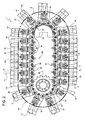
- Number 1 in Figure 1 indicates as a whole a folding unit for a packaging machine (not shown) for continuously producing sealed packages 2 of a pourable food product, such as pasteurized or UHT milk, fruit juice, wine, etc., from a known tube of packaging material (not shown).
- a packaging machine not shown
- sealed packages 2 of a pourable food product such as pasteurized or UHT milk, fruit juice, wine, etc.
- the tube is formed in known manner upstream from unit 1 by longitudinally folding and sealing a known web (not shown) of heat-seal sheet material, which may comprise a base layer for stiffness and strength, which may be formed by a layer of fibrous material, e.g. paper, or of mineral-filled polypropylene material, and a number of layers of heat-seal plastic material, e.g. polyethylene film, covering both sides of the base layer.
- the packaging material may also comprises a layer of gas- and light-barrier material, e.g.
- an aluminium foil or an ethyl vinyl alcohol (EVOH) foil which is superimposed on a layer of heat-seal plastic material, and is in turn covered with another layer of heat-seal plastic material forming the inner face of the package 2 eventually contacting the food product.
- EVOH ethyl vinyl alcohol
- the tube of packaging material is then filled with the food product for packaging, and is sealed and cut along equally spaced cross sections to form a number of pillow packs 3 ( Figure 15 ), which are then transferred to unit 1 where they are folded mechanically to form respective packages 2.
- the packaging material may be cut into blanks, which are formed into packages 2 with forming spindles, and packages 2 are filled with the food product and sealed.
- packages 2 are filled with the food product and sealed.
- Tetra Rex registered trademark
- pillow packs 3 are transferred to unit 1 by using an in-feed conveyor 41 ( Figure 1 ), which is described in more detail in the European application “Feeding unit and method for feeding sealed pillow packs of pourable food products to a folding unit", filed by the Applicant concurrently with the present invention.
- Unit 1 also feeds folded package 2 to out-feed conveyor 42, shown in Figure 1 .
- a package 2 which has a longitudinal sealing band 4, formed to produce the tube of packaging material from the web folded into a cylinder, extends along one side of each pack 3, which is closed at the opposite ends by respective transverse sealing bands 5, 6 perpendicular to and joined to longitudinal sealing band 4.
- Each pack 3 has an axis A, and comprises a main body 7 and opposite, respectively top and bottom, end portions 8, 9 tapering from main body 7 towards respective transverse sealing bands 5, 6.
- Main body 7 of each pack 3 is bounded laterally by four lateral walls 10a, 10b and four corner walls 11 alternate to each other, in the embodiment shown in Figure 15 .
- Walls 10a (10b) are opposite to each other. In the very same way, walls 11 are opposite, in pairs, to each other.
- Each wall 10a, 10b comprises a central rectangular stretch 13 and a pair of opposite, respective top and bottom, end stretches 14 which are interposed between stretch 13 and end portions 8, 9 of pack 3.
- stretches 13 are substantially parallel to axis A.
- Each end stretch 14 is substantially in the form of an isosceles trapezium, which slopes slightly relative to axis A, and has a major edge defined by respective end portions 8, 9.
- Each wall 11 comprises a central rectangular stretch 15 and a pair opposite, respective top and bottom, end stretches 16 which are interposed between stretch 15 and end portions 8, 9 of pack 3.
- stretches 15 are substantially parallel to axis A.
- Each end stretch 16 is substantially in the form of an isosceles triangle, which slopes slightly relative to axis A and converges from relative stretch 15 towards corresponding end portions 8, 9.
- Each end portion 8, 9 is defined by two walls 12, each substantially in the form of an isosceles trapezium, which slope slightly towards each other with respect to a plane perpendicular to axis A, and have minor edges defined by respective end edges of portions 14 of respective wall 10a, and major edges joined to each other by respective sealing bands 5, 6.
- Longitudinal sealing band 4 extends between transverse sealing bands 5 and 6, and along the whole of one wall 10a and the corresponding walls 12 on the same side as wall 10a.
- Each pack 3 also comprises, for each end portion 8, 9, a respective substantially elongated rectangular end fin 17, 18 projecting in the direction of axis A from relative pack 3; and two substantially triangular flaps 19, 20 projecting laterally on opposite sides of main body 7 and defined by end portions of relative walls 12.
- each end fin 17, 18 extends along a direction orthogonal to axis A.
- unit 1 presses end portions 8, 9 of relative pack 3 down flat towards each other, and at the same time folds respective fins 17, 18 onto end portions 8, 9.
- unit 1 folds flaps 20 onto top stretches 14 of respective walls 10b and folds flaps 19 onto previously folded fin 17, on the opposite side of end portion 9.
- unit 1 substantially comprises:
- Heating device 27 is, in particular, arranged between folding means 23 and pressure device 28 along forming path B.
- conveyor 34 basically comprises an endless transport element, in the example shown a chain 60, formed by a plurality of mutually hinged rigid modules or links 35 and looped about a pair of coaxial driving sprockets 26 and a cam 25.
- Chain 60 comprises a straight horizontal top branch 30, a bottom branch 31 substantially parallel to branch 30, and two curved C-shaped portions 32, 33, which are positioned with their concavities facing each other and connect branches 30 and 31; more specifically, C-shaped portion 32 cooperates with driving sprockets 26, whilst C-shaped portion 33 cooperates with cam 25.
- Each link 35 comprises a substantially flat plate 36 adapted to receive a relative pack 3, and a paddle 43, which projects perpendicularly from plate 36 on the opposite side of driving sprockets 26 and cam 25 and which cooperates with and pushes a corresponding wall 10 of a relative pack 3 to feed it along path B.
- Cam 25 is described in more detail in the European application "Folding unit for producing folded packages of pourable food products from relative sealed packs", filed by the Applicant concurrently with the present invention.
- unit 1 comprises ( Figures 5 and 6 ) a plurality of pairs of shells 50 which are integrally movable along path B and are movable along a direction C transversal to path B; shells 50 of each pair may be arranged in:
- shells 50 may be arranged also in a closed position, in which they grip folded package 2 but substantially do not exert any pressure thereon.
- station 21 is defined by C-shaped portion 32 and station 22 is defined by bottom branch 31 in a position closer to C-shaped portion 32 than to C-shaped portion 33.
- Path B comprises, proceeding from station 21 to station 22,:
- stretch P1 is defined by a part of C-shaped portion 32 and stretch P2 is defined by top branch 30 of chain 60.
- Portion Q is defined by C-shaped portion 33, and portion R is defined by part of bottom branch 31 of chain 60.
- Folding means 23 cooperate cyclically with each pack 3 along portion P.
- Folding means 24 are defined by links 35 and, therefore, move together with chain 60 along path B.
- folding means 24 flatten end portion 9, folds relative fin 18 onto portion 9 and bend flaps 20 towards axis A and end portion 8, as relative pack 2 is carried along stretch P1 of path P ( Figure 8 ).
- Heating device 27 acts on bent flaps 19, 20 to melt the external layer of the packaging material and seal the flaps 19, 20 before they are pressed against end portion 8 and relative walls 10b respectively, as pack 2 is carried along stretch P2 of portion P ( Figure 9 ).
- shells 50 of each pair cyclically move according to the following work cycle.
- Shells 50 of each pair are arranged in the open position at station 21, move from open to fully closed position along stretch P1 and an initial part of stretch P2, and reach the fully closed position along a remaining part of stretch P2. In the embodiment shown, shells 50 reach the fully closed position downstream from heating device 27 and upstream from pressing device 28, proceeding according to the advancing direction of chain 60.
- shells 50 of each link 35 perform two functions:
- shells 50 of each pair move from the fully closed position into the closed position at the beginning of portion Q.
- shells 50 integrally move parallel to direction C and relative to respective paddle 43 ( Figure 6 ).
- shells 50 move away relative to each other for a distance, for example, of 2-4 mm, when they move from the fully closed position to the closed position.
- Link 35 comprises ( Figures 12 to 14 ):
- plate 36 is arranged below, and then support, pack 3 (or package 2) along portion P and a starting stretch of portion Q of forming path B.
- plate 36 is arranged above package 2 along portion R of forming path B. Accordingly, folded package 2 is released, under the gravity action at station 22, to conveyor 42.
- Shells 50 define, on their sides opposite to arm 51, relative surfaces 52 which are adapted to cooperate with pack 3 and which face each other.
- Surfaces 52 mirror the lateral surface of packages 2 to be folded, so as to control the final shape of packages 2.
- each surface 52 mirrors a relative walls 10b and parts of relative walls 11.
- Each arm 51 comprises, on its end opposite to relative shell 50, a roller 55.
- Each slide 53 is arranged between relative shells 50 and rollers 55 of relative arm 51. Furthermore, each slide 53 may slide parallel to direction C relative to guide 54.
- each arm 51 is integral with relative shell 50.
- Paddles 43 mirror the shape of walls 10 and of the part of relative walls 11 they cooperate with.
- Plate 36 of link 35 comprises ( Figure 12 and 13 ):
- Plate 36 of link 35 also defines:
- Slots 39 are arranged on lateral sides of portion 37 and slots 39, 40 are defined between portions 37, 38.
- Slots 39 extend, along direction D, between slot 40 and relative bridges 47 which integrally connect portions 36, 37.
- Folding means 24 comprises, for each link 35,:
- slot 40 remains open when plate 72 is in the second position.
- Link 35 also comprises a pair of toothed sectors 73 staggered along relative direction C and which protrude from link 35 downstream from plate 36, proceeding according to the advancing direction of chain 60.
- Plate 72 integrally comprises two arms 90 arranged on lateral sides of paddle 43, and a central element 91 interposed between arms 90.
- Each arm 90 comprises a wedge 75 arranged on the side of paddle 43 and a rack 76 ( Figure 11 ) arranged on the side of cam 25 and driving sprocket 26.
- Element 91 is housed within slot 40 when plate 72 is in the first position, and is arranged upstream from slot when plate 72 is in the second position.
- wedges 75 are triangular in cross section and converge towards a mid-direction of link 35.
- Wedges 75 are arranged downstream from racks 76, proceeding according to an advancing direction of chain 60.
- Toothed sectors 73 of each link 35 mesh with racks 76 of the following link 35, proceeding along the advancing direction of chain 60 ( Figure 11 ).
- Plate 72 is arranged in the second position at station 21, moves from the second to the first position along stretch P1 of path B, remains in the first position along stretch P2 of path B, moves from the first to the second position along portion Q of path B, and remains in the second position along portion R of path B and from station 22 to station 21.
- fin 18 of pack 3 is arranged within open slot 40 of link 35 at station 21.
- plate 72 of link 35 moves in the first position and engages slot 40, fin 18 is folded onto end portion 8.
- wedges 75 raise flaps 20 towards end portion 8 and bend flaps 20 relative to axis A, up to when they reach the position shown in Figure 8 .
- the corresponding shells 50 as moving from the open to the fully closed position, press flaps 20 against top stretches 14 of relative walls 12, downstream from folding means 23 and heating device 17, proceeding according to the advancing direction of chain 60.
- Unit 1 also comprises a pair of cams 61 ( Figures 3 and 4 ) adapted to control the movement of each pair of shells 50 between relative fully closed position, closed position and open position, as each pair of shells 50 advances along path B.
- cams 61 Figures 3 and 4
- cams 61 also control the movement of each pair of shells 50 integrally to each other along direction C and relative to paddle 43 of corresponding link 35.
- cams 61 are arranged on opposite lateral sides of chain 60.
- One cam 61 comprises a groove 62 which is engaged by rollers 55 of first shells 50.
- the other cam 61 comprises a further groove 62 which is engaged by rollers 55 of second shells 50.
- grooves 62 comprise, proceeding from station 21 to station 22,:
- Folding means 23 comprise a guide member 45 fitted in a fixed position between station 21 and heating device 27 ( Figure 1 ).
- Guide member 45 defines a contrast surface 46 ( Figure 1 ) converging towards chain 60 and cooperating in a sliding manner with end portion 9 of each pack 3 to compress and flatten end portion 9 towards chain 60.
- Frame 29 also comprises a pair of fixed sides 68 (only one shown in Figure 1 ) for laterally containing packs 3 along path B, located on opposite sides of chain 60, and extending between station 21 and heating device 27.
- Heating device 27 comprises ( Figures 1 , 8 and 9 ) :
- Pressure device 28 comprises ( Figure 1 ) a belt 80 wound onto a drive wheel 81 and a driven wheel 82.
- Belt 80 comprises, on its outer surface opposite to wheels 81, 82, a plurality of projections 83 which are adapted to press flaps 19 of each pack 3 onto relative fin 17.
- each package 2 in formation is controlled, downstream from heating device 27, within a compartment bounded by:
- unit 1 Operation of unit 1 will be described with reference to one pack 3 and to relative link 35 as of an initial instant, in which pack 3 is fed from the in-feed conveyor to chain 60 at station 21 of path B.
- link 35 is moving at the beginning of stretch P1 and therefore slot 40 is open. Furthermore, shells 50 are arranged in the open position.
- pack 3 is positioned with end fin 18 facing plate 72 of link 35, and slides on one wall 10a along relative paddle 43, so that fin 18 is parallel to paddle 43, until when fin 18 enters open slot 40.
- pack 3 is arranged above and, therefore, supported by plate 36 of link 35.
- contrast surface 46 cooperates in a sliding manner with end portion 8 of pack 3.
- portions 8 and 9 are flattened towards each other, fin 17 is folded onto portion 8 and flaps 20 are bent relative to portion 8 towards axis A and on the opposite side of portion 8, as shown in Figure 9 .
- each pair of consecutive links 35 moves towards each other along stretch P1.
- racks 76 of the subsequent link 35 are thrust by toothed sectors 73 of the precedent link 35, proceeding according to the advancing direction of chain 60 along stretch P1 of forming path B.
- plate 72 of the subsequent link 35 moves from the second to the first position, in which it engages slot 40.
- nozzles 70, 71 direct air onto flaps 19, 20 of pack 3, to partly and locally melt the packaging material of flaps 19, 20 ( Figure 9 ).
- shells 50 contact walls 10b, 11 of packs 3, and press flaps 20 onto relative top stretches 14 of walls 11 as flaps 20 cool. In this condition, shells 50 are arranged in the fully closed position.
- pack 3 is arranged below belt 80 and projections 83 press flaps 20 onto portion 9, as flaps 20 cool.
- the volume of folded package 2 is controlled by two paddles 43 of respective consecutive links 35, by shells 50 arranged in the fully closed position, and by projections 83 of belt 80.
- Folded package 2 then move along portion Q of path P.
- shells 50 move relative to each other from the fully closed to the closed position, in which they grip package 2 but substantially do not exert any pressure thereon.
- shells 50 move together with package 2 relative to paddle 43 parallel to direction C, along portion Q.
- shells 50 together with folded package 2 are staggered from paddle 43, at the end of portion Q.
- each pair of consecutive links 35 move away from each other.
- racks 76 of the subsequent link 35 move away from toothed sectors 73 of the precedent link 35.
- plate 72 of the subsequent link 35 moves back from the first to the second position, in which it leaves free slot 40.
- folded package 2 is arranged below plate 36 and is supported by the shells 50 arranged in the closed position.
- paddle 43 does not interfere with the release of package 2.
- shells 50 are conveyed by chain 60 towards station 21.
- shells 50 are in the closed position when the forming of relative package 2 is completed. In this way, surface 53 of shells 50 are active in controlling the shape of package 2 in formation.
- packages 2 is highly precise and repeatable, even when package 2 has a round or polygonal cross-section.
- folded packages 2 are held by shells 50 along portion R of path B, in which packages 2 are below relative plates 36.
- packages 2 are vertical when they are directly discharged on out-feed conveyor 42 under the gravity action.
- shells 50 may move with respect to relative paddle 43 along portion Q and parallel to direction C.
- shells 50 and relative packages 2 are staggered from relative paddle 43, along portion Q of path B and at station 22.
- unit 1 could comprise a rotating device for rotating packages 2 before they are released at station 22.
- Unit 1 could comprise only one cam 61.
Landscapes
- Engineering & Computer Science (AREA)
- Mechanical Engineering (AREA)
- Auxiliary Devices For And Details Of Packaging Control (AREA)
- Making Paper Articles (AREA)
- Closing Of Containers (AREA)
- Containers And Plastic Fillers For Packaging (AREA)
Description
- The present invention relates to a folding unit and to a method for producing folded packages of pourable food products from relative sealed packs.
- As is known, many food products, such as fruit juice, pasteurized or UHT (ultra-high-temperature treated) milk, wine, tomato sauce, etc., are sold in packages made of sterilized packaging material.
- A typical example of this type of package is the parallelepiped-shaped package for liquid or pourable food products known as Tetra Brik Aseptic (registered trademark), which is made by folding and sealing laminated strip packaging material.
- The packaging material has a multilayer structure substantially comprising a base layer for stiffness and strength, which may comprise a layer of fibrous material, e.g. paper, or of mineral-filled polypropylene material; and a number of layers of heat-seal plastic material, e.g. polyethylene film, covering both sides of the base layer.
- In the case of aseptic packages for long-storage products, such as UHT milk, the packaging material may also comprise a layer of gas- and light-barrier material, e.g. an aluminium foil or an ethyl vinyl alcohol (EVOH) foil, which is superimposed on a layer of heat-seal plastic material, and is in turn covered with another layer of heat-seal plastic material forming the inner face of the package eventually contacting the food product.
- As is known, packages of this sort are produced on fully automatic packaging machines, on which a continuous tube is formed from the web-fed packaging material. The web of packaging material is sterilized on the packaging machine, e.g. by applying a chemical sterilizing agent, such as a hydrogen peroxide solution, which, once sterilization is completed, is removed from the surfaces of the packaging material, e.g. evaporated by heating. The web of packaging material so sterilized is maintained in a closed, sterile environment, and is folded and sealed longitudinally to form a vertical tube.
- The tube is filled continuously downwards with the sterilized or sterile-processed food product, and is sealed and then cut along equally spaced cross sections to form pillow packs, which may be fed to a folding unit to form the finished packages.
- More specifically, the pillow packs substantially comprise a main portion, and opposite top and bottom end portions tapering from the main portions towards respective top and bottom sealing bands which extend substantially orthogonal to the axis of the pack. In detail, each end portion is defined by a pair of respective trapezoidal walls which extend between main portion of the pack and the relative sealing band.
- Each pillow pack also comprises, for each top and bottom end portion, an elongated substantially rectangular fin projecting from respective sealing bands; and a pair of substantially triangular flaps projecting from opposite sides of relative end portion and defined by respective trapezoidal walls.
- The end portions are pressed towards each other by the folding unit to form flat opposite end walls of the pack, while at the same time folding the flaps of the top portion onto respective lateral walls of the main portion and the flaps of the bottom portion onto the bottom sealing band.
- Packaging machines for producing packages of the above type are known, substantially comprising:
- an in-feed conveyor;
- a folding unit receiving the pillow packs from the in-feed conveyor and adapted to fold these pillow packs to form the parallelepiped-shaped packages;
- a transfer unit for transferring and up-ending the folded packages, which is arranged downstream from the folding unit and receives the sealed packages from the folding unit; and
- an out-feed conveyor which receives folded packages from the transfer unit and moves them away from the packaging machine.
- Folding units are known, for example from
EP-B-0887261 in the name of the same Applicant, which typically comprise: - a chain conveyor for feeding packs continuously along a forming path from a supply station to an output station;
- a number of folding devices arranged in fixed positions relative to the forming path and cooperating with packs to perform relative folding operations thereon;
- a heat-sealing device acting on respective triangular flaps of each pack to be folded, to melt the external layer of the packaging material and seal flaps onto respective walls of the pack; and
- a pressing device cooperating with each pack to hold the triangular portions on respective walls as these portions cool.
- In detail, the chain conveyor comprises a top straight branch, a bottom straight branch and two curved portions which are opposite to each other and connect, on respective opposite sides, the top and bottom branches.
- More precisely, the axes of the packs are slightly backwards inclined relative to a vertical direction when they are fed to the chain conveyor at the supply station, and are substantially vertical when packs are fed along the top branch. Furthermore, the folded packages are slightly forwards inclined relative to the vertical direction, when they reach the output station.
- In other words, when moving along the forming path, the packs and the corresponding folded packages are arranged above and are, therefore, continuously supported by the chain conveyor.
- The pressing device comprises three endless belts which define, between them and together with the top branch of the chain, a forming passage having a constant rectangular section, and defining the outer contour of the finished packages.
- Transfer units are known, for example from
EP-B-0887268 in the name of the same Applicant. - In detail, the known transfer units move the packages successively along a path from an in-feed station to an out-feed station, and simultaneously up-end the packages from an in-feed position, in which the packages are positioned with their axis tilted roughly 15° to the horizontal, into an out-feed position, in which the packages are positioned with their axis substantially vertical.
- More specifically, the in-feed position of the transfer unit substantially coincides with the output station of the folding unit.
- Known transfer units substantially comprise a rotary member having a number of push arms which cooperate with respective packages to push them along the path; and a fixed guide which extends along this path and cooperates with the packages to ease them from the tilted in-feed position to the out-feed position.
- Though efficient, packaging machines of the above type leave room for improvement.
- As a matter of fact, a wide range of modified package shapes has been developed which are different from the parallelepiped package.
- In particular, packages with a slightly rounded or an octagonal cross section have been developed.
- For these packages, the Applicant has found that the forming operation may require some adjustments. This is mainly due to the fact that the forming passage must be, in this case, polygonal whereas the endless belts have substantially flat surfaces cooperating with the folded package.
- Furthermore, the Applicant has found that these modified packages tend to rotate about their own axis, as they are fed from the in-feed to the out-feed position.
- As a result, there is some risk that turned packages stop along the path defined by the transfer unit and causes the stop of the transfer unit and, therefore, of the whole packaging machine.
-
DE-U-1913258 discloses a folding unit according to the preamble of claim 1. - It is an object of the present invention to provide a folding unit for a pourable food product machine, designed to provide a straightforward, low-cost solution to at least one of the aforementioned drawbacks, typically associated with the known folding unit.
- According to the present invention, there is provided a folding unit for producing folded packages of pourable food products from relative sealed packs, as claimed in claim 1.
- The present invention also relates to a method for producing folded packages of pourable food product from relative sealed packs, as claimed in
claim 9. - A preferred, non-limiting embodiment of the present invention will be described by way of example with reference to the accompanying drawings, in which:
-
Figure 1 shows a side view, with parts removed for clarity, of a folding unit in accordance with the present invention for producing folded packages of pourable food products from sealed pillow packs; -
Figure 2 is an enlarged side view of the folding unit ofFigure 1 , with parts removed for clarity; -
Figure 3 and4 show respectively bottom and top perspective views, with parts removed for clarity, of the folding unit ofFigure 2 ; -
Figure 5 shows a perspective view, with parts removed for clarity, of the bottom part folding unit ofFigures 1 to 4 ; -
Figures 6 to 10 show some components of the unit ofFigure 1 to 5 in different operative conditions; -
Figures 11 to 14 are perspective views of further components of the folding unit ofFigure 1 to 5 ; and -
Figure 15 shows in a perspective enlarged view a pack the folding unit ofFigures 1 to 14 is fed with. - Number 1 in
Figure 1 indicates as a whole a folding unit for a packaging machine (not shown) for continuously producing sealedpackages 2 of a pourable food product, such as pasteurized or UHT milk, fruit juice, wine, etc., from a known tube of packaging material (not shown). - The tube is formed in known manner upstream from unit 1 by longitudinally folding and sealing a known web (not shown) of heat-seal sheet material, which may comprise a base layer for stiffness and strength, which may be formed by a layer of fibrous material, e.g. paper, or of mineral-filled polypropylene material, and a number of layers of heat-seal plastic material, e.g. polyethylene film, covering both sides of the base layer. In the case of an
aseptic package 2 for long-storage products, such as UHT milk, the packaging material may also comprises a layer of gas- and light-barrier material, e.g. an aluminium foil or an ethyl vinyl alcohol (EVOH) foil, which is superimposed on a layer of heat-seal plastic material, and is in turn covered with another layer of heat-seal plastic material forming the inner face of thepackage 2 eventually contacting the food product. - The tube of packaging material is then filled with the food product for packaging, and is sealed and cut along equally spaced cross sections to form a number of pillow packs 3 (
Figure 15 ), which are then transferred to unit 1 where they are folded mechanically to formrespective packages 2. - Alternatively, the packaging material may be cut into blanks, which are formed into
packages 2 with forming spindles, andpackages 2 are filled with the food product and sealed. One example of this type of packages is the so-called "gable-top" package known by the trade name Tetra Rex (registred trademark). - In detail,
pillow packs 3 are transferred to unit 1 by using an in-feed conveyor 41 (Figure 1 ), which is described in more detail in the European application "Feeding unit and method for feeding sealed pillow packs of pourable food products to a folding unit", filed by the Applicant concurrently with the present invention. - Unit 1 also feeds folded
package 2 to out-feed conveyor 42, shown inFigure 1 . - With reference to
Figure 15 , an embodiment of apackage 2 is shown which has a longitudinal sealing band 4, formed to produce the tube of packaging material from the web folded into a cylinder, extends along one side of eachpack 3, which is closed at the opposite ends by respectivetransverse sealing bands 5, 6 perpendicular to and joined to longitudinal sealing band 4. - Each
pack 3 has an axis A, and comprises amain body 7 and opposite, respectively top and bottom,end portions 8, 9 tapering frommain body 7 towards respectivetransverse sealing bands 5, 6. -
Main body 7 of eachpack 3 is bounded laterally by fourlateral walls corner walls 11 alternate to each other, in the embodiment shown inFigure 15 . -
Walls 10a (10b) are opposite to each other. In the very same way,walls 11 are opposite, in pairs, to each other. - Each
wall rectangular stretch 13 and a pair of opposite, respective top and bottom,end stretches 14 which are interposed betweenstretch 13 andend portions 8, 9 ofpack 3. - In detail, stretches 13 are substantially parallel to axis A. Each
end stretch 14 is substantially in the form of an isosceles trapezium, which slopes slightly relative to axis A, and has a major edge defined byrespective end portions 8, 9. - Each
wall 11 comprises a centralrectangular stretch 15 and a pair opposite, respective top and bottom, end stretches 16 which are interposed betweenstretch 15 andend portions 8, 9 ofpack 3. - In detail, stretches 15 are substantially parallel to axis A. Each
end stretch 16 is substantially in the form of an isosceles triangle, which slopes slightly relative to axis A and converges fromrelative stretch 15 towardscorresponding end portions 8, 9. - Each
end portion 8, 9 is defined by twowalls 12, each substantially in the form of an isosceles trapezium, which slope slightly towards each other with respect to a plane perpendicular to axis A, and have minor edges defined by respective end edges ofportions 14 ofrespective wall 10a, and major edges joined to each other byrespective sealing bands 5, 6. - Longitudinal sealing band 4 extends between transverse sealing
bands 5 and 6, and along the whole of onewall 10a and thecorresponding walls 12 on the same side aswall 10a. - Each
pack 3 also comprises, for eachend portion 8, 9, a respective substantially elongatedrectangular end fin relative pack 3; and two substantiallytriangular flaps main body 7 and defined by end portions ofrelative walls 12. - More precisely, each
end fin - To form a
package 2, unit 1 pressesend portions 8, 9 ofrelative pack 3 down flat towards each other, and at the same time foldsrespective fins end portions 8, 9. - Furthermore, unit 1 folds flaps 20 onto top stretches 14 of
respective walls 10b and foldsflaps 19 onto previously foldedfin 17, on the opposite side ofend portion 9. - With reference to
Figure 1 ,2 and15 , unit 1 substantially comprises: - a
frame 29; - an
endless conveyor 34 for feedingpacks 3 continuously along a forming path B from asupply station 21 to an output station 22 (both shown only schematically); - folding means 23 which cooperate cyclically with each
pack 3 to flatten end portion 8, foldrelative fin 17 onto end portion 8, and foldflaps 19 onto previously flattened end portion 8 on the opposite side ofend portion 9; - folding means 24 for flattening
end portion 9, foldingrelative fin 18 ontoportion 9 and bendingflaps 20 towards axis A andend portion 9; - a
heating device 27 acting onbent flaps flaps relative walls 10b respectively; and - a
pressing device 28 cooperating with eachpack 3 to holdflaps 19 onto flattenedfin 17 asflaps 19 cool. -
Heating device 27 is, in particular, arranged between folding means 23 andpressure device 28 along forming path B. - With particular reference to
Figures 2 ,4 ,5 and6 ,conveyor 34 basically comprises an endless transport element, in the example shown achain 60, formed by a plurality of mutually hinged rigid modules orlinks 35 and looped about a pair of coaxial drivingsprockets 26 and acam 25. -
Chain 60 comprises a straight horizontaltop branch 30, abottom branch 31 substantially parallel tobranch 30, and two curved C-shapedportions branches portion 32 cooperates with drivingsprockets 26, whilst C-shapedportion 33 cooperates withcam 25. - Each
link 35 comprises a substantiallyflat plate 36 adapted to receive arelative pack 3, and apaddle 43, which projects perpendicularly fromplate 36 on the opposite side of drivingsprockets 26 andcam 25 and which cooperates with and pushes a corresponding wall 10 of arelative pack 3 to feed it along path B. -
Cam 25 is described in more detail in the European application "Folding unit for producing folded packages of pourable food products from relative sealed packs", filed by the Applicant concurrently with the present invention. - Advantageously, unit 1 comprises (
Figures 5 and6 ) a plurality of pairs ofshells 50 which are integrally movable along path B and are movable along a direction C transversal to path B;shells 50 of each pair may be arranged in: - a fully closed position in which they exert a pressure onto a
relative pack 3, so as to complete a folding operation thereon; and - an open position in which they are detached from folded package 2 (
Figures 5 and6 ). - Furthermore,
shells 50 may be arranged also in a closed position, in which they grip foldedpackage 2 but substantially do not exert any pressure thereon. - In detail,
station 21 is defined by C-shapedportion 32 andstation 22 is defined bybottom branch 31 in a position closer to C-shapedportion 32 than to C-shapedportion 33. - Path B comprises, proceeding from
station 21 tostation 22,: - a portion P starting from
station 21, comprising a curved and a straight stretches P1, P2, along which packs 3 are folded intorelative packages 2; - a curved portion Q along which folded
packages 2 are overturned of 180 degrees; and - a straight portion R arranged downstream from curved portion Q and upstream from
station 22. - In detail, stretch P1 is defined by a part of C-shaped
portion 32 and stretch P2 is defined bytop branch 30 ofchain 60. Portion Q is defined by C-shapedportion 33, and portion R is defined by part ofbottom branch 31 ofchain 60. - Folding means 23 cooperate cyclically with each
pack 3 along portion P. - Folding means 24 are defined by
links 35 and, therefore, move together withchain 60 along path B. - In detail, folding means 24 flatten
end portion 9, foldsrelative fin 18 ontoportion 9 and bendflaps 20 towards axis A and end portion 8, asrelative pack 2 is carried along stretch P1 of path P (Figure 8 ). -
Heating device 27 acts onbent flaps flaps relative walls 10b respectively, aspack 2 is carried along stretch P2 of portion P (Figure 9 ). - In detail,
shells 50 of each pair cyclically move according to the following work cycle. -
Shells 50 of each pair are arranged in the open position atstation 21, move from open to fully closed position along stretch P1 and an initial part of stretch P2, and reach the fully closed position along a remaining part of stretch P2. In the embodiment shown,shells 50 reach the fully closed position downstream fromheating device 27 and upstream from pressingdevice 28, proceeding according to the advancing direction ofchain 60. - When
shells 50 are arranged in the fully closed position they exert a certain pressure onrelative walls - More precisely, as moving between the open and the fully closed position along stretch P2 of portion P,
shells 50 of eachlink 35 perform two functions: - firstly, they complete the bending of
flaps 20 onto top stretches 14 ofrelative walls 10b; and - then, they press flaps 20, which have been previously bent and heated, onto
stretches 14 ofrelative walls 10b. - Furthermore,
shells 50 of each pair move from the fully closed position into the closed position at the beginning of portion Q. - Along portion Q,
shells 50 integrally move parallel to direction C and relative to respective paddle 43 (Figure 6 ). - In the embodiment shown,
shells 50 move away relative to each other for a distance, for example, of 2-4 mm, when they move from the fully closed position to the closed position. - In the following of the present description, only one
link 35 will be described in detail, being clear that alllinks 35 are identical to each other. -
Link 35 comprises (Figures 12 to 14 ): -
plate 36; - paddle 43;
- a pair of
shells 50 which may move relative to paddle 43 along direction C; - a pair of
arms 51 connected torelative shells 50, elongated parallel to direction C and comprising each arelative slide 53; and - a pair of
guides 54 which extend on opposite sides ofrelative paddle 43 along direction C, and relative to which slides 53 move parallel to direction C. - Referring again to
Figures 1 and2 ,plate 36 is arranged below, and then support, pack 3 (or package 2) along portion P and a starting stretch of portion Q of forming path B. - Conversely,
plate 36 is arranged abovepackage 2 along portion R of forming path B. Accordingly, foldedpackage 2 is released, under the gravity action atstation 22, toconveyor 42. -
Shells 50 define, on their sides opposite toarm 51,relative surfaces 52 which are adapted to cooperate withpack 3 and which face each other. -
Surfaces 52 mirror the lateral surface ofpackages 2 to be folded, so as to control the final shape ofpackages 2. - In the embodiment shown, each
surface 52 mirrors arelative walls 10b and parts ofrelative walls 11. - Each
arm 51 comprises, on its end opposite torelative shell 50, aroller 55. - Each
slide 53 is arranged betweenrelative shells 50 androllers 55 ofrelative arm 51. Furthermore, each slide 53 may slide parallel to direction C relative to guide 54. - In the embodiment shown, each
arm 51 is integral withrelative shell 50. -
Paddles 43 mirror the shape of walls 10 and of the part ofrelative walls 11 they cooperate with. -
Plate 36 oflink 35 comprises (Figure 12 and13 ): - a
rectangular portion 37 from whichpaddle 43 protrudes; and - a contoured
portion 38 which surroundsportion 37. -
Plate 36 oflink 35 also defines: - a pair of through
slots 39 which are arranged on opposite lateral sides ofpaddle 43 and elongated along a direction D tangent to forming path B and orthogonal to direction C; and - a through
slot 40 which is in communication withslots 39, is arranged downstream fromslots 39 andportion 37 proceeding according to the advancing direction ofchain 60, and which extends parallel to direction C. -
Slots 39 are arranged on lateral sides ofportion 37 andslots portions -
Slots 39 extend, along direction D, betweenslot 40 andrelative bridges 47 which integrally connectportions -
Slot 40 extends parallel to direction C. Folding means 24 comprises, for eachlink 35,: -
plate 36 which is integrally movable withpaddle 43 along forming path B; and - a C-shaped
movable plate 72 which may move along direction D relative to paddle 43 andplate 36 between a first position (Figure 12 ) in which it engagesslot 40, so as to foldend fin 18 housed therein, and a second position (Figure 13 ) in which it leavesfree slot 40. - In particular,
slot 40 remains open whenplate 72 is in the second position. -
Link 35 also comprises a pair oftoothed sectors 73 staggered along relative direction C and which protrude fromlink 35 downstream fromplate 36, proceeding according to the advancing direction ofchain 60. -
Plate 72 integrally comprises twoarms 90 arranged on lateral sides ofpaddle 43, and acentral element 91 interposed betweenarms 90. - Each
arm 90 comprises awedge 75 arranged on the side ofpaddle 43 and a rack 76 (Figure 11 ) arranged on the side ofcam 25 and drivingsprocket 26. -
Element 91 is housed withinslot 40 whenplate 72 is in the first position, and is arranged upstream from slot whenplate 72 is in the second position. - In the embodiment shown,
wedges 75 are triangular in cross section and converge towards a mid-direction oflink 35. -
Wedges 75 are arranged downstream fromracks 76, proceeding according to an advancing direction ofchain 60. -
Toothed sectors 73 of eachlink 35 mesh withracks 76 of the followinglink 35, proceeding along the advancing direction of chain 60 (Figure 11 ). -
Plate 72 is arranged in the second position atstation 21, moves from the second to the first position along stretch P1 of path B, remains in the first position along stretch P2 of path B, moves from the first to the second position along portion Q of path B, and remains in the second position along portion R of path B and fromstation 22 tostation 21. - More precisely,
fin 18 ofpack 3 is arranged withinopen slot 40 oflink 35 atstation 21. Whenplate 72 oflink 35 moves in the first position and engagesslot 40,fin 18 is folded onto end portion 8. At the same time,wedges 75 raise flaps 20 towards end portion 8 and bendflaps 20 relative to axis A, up to when they reach the position shown inFigure 8 . - The corresponding
shells 50, as moving from the open to the fully closed position, press flaps 20 against top stretches 14 ofrelative walls 12, downstream from folding means 23 andheating device 17, proceeding according to the advancing direction ofchain 60. - Unit 1 also comprises a pair of cams 61 (
Figures 3 and4 ) adapted to control the movement of each pair ofshells 50 between relative fully closed position, closed position and open position, as each pair ofshells 50 advances along path B. - Furthermore,
cams 61 also control the movement of each pair ofshells 50 integrally to each other along direction C and relative to paddle 43 ofcorresponding link 35. - In detail,
cams 61 are arranged on opposite lateral sides ofchain 60. - One
cam 61 comprises agroove 62 which is engaged byrollers 55 offirst shells 50. - The
other cam 61 comprises afurther groove 62 which is engaged byrollers 55 ofsecond shells 50. - With reference to
Figures 3 to 5 ,grooves 62 comprise, proceeding fromstation 21 tostation 22,: - relative
straight portions 63 which are adapted to keepshells 50 of each pair in the open position; - relative converging portions 64 which are adapted to move
shells 50 from relative open to relative fully closed portion along stretch P2 of path P; - relative
straight portions 65 which are adapted to keepshells 50 of each pair in respective fully closed position; - relative
curved portions 66 which are adapted to moveshells 50 from respective fully closed to respective closed positions;curved portions 66 also move correspondingshells 50 with respect to correspondingpaddle 43 and parallel to respective directions C; and - relative
curved portions 67 which are adapted to moveshells 50 from respective closed to respective open positions. - Folding means 23 comprise a
guide member 45 fitted in a fixed position betweenstation 21 and heating device 27 (Figure 1 ). -
Guide member 45 defines a contrast surface 46 (Figure 1 ) converging towardschain 60 and cooperating in a sliding manner withend portion 9 of eachpack 3 to compress and flattenend portion 9 towardschain 60. -
Frame 29 also comprises a pair of fixed sides 68 (only one shown inFigure 1 ) for laterally containingpacks 3 along path B, located on opposite sides ofchain 60, and extending betweenstation 21 andheating device 27. -
Heating device 27 comprises (Figures 1 ,8 and9 ) : - an
assembly air device 69 fitted to frame 29; - a pair of
first nozzles 70 connected toassembly 69 and adapted to direct hot air ontoflaps 20 of eachpack 3 before eachpack 3 reaches finalpressing device 28; and - a pair of
second nozzles 71 connected toassembly 69 and adapted to direct hot air ontoflaps 19 of eachpack 3 before a relative pair ofshells 50 reaches the fully closed position. -
Pressure device 28 comprises (Figure 1 ) abelt 80 wound onto adrive wheel 81 and a drivenwheel 82.Belt 80 comprises, on its outer surface opposite towheels projections 83 which are adapted to pressflaps 19 of eachpack 3 ontorelative fin 17. - The volume of each
package 2 in formation is controlled, downstream fromheating device 27, within a compartment bounded by: - paddles 43 of
relative link 35 and of thelink 35 arranged immediately downstream proceeding according to the advancing direction ofchain 60; -
shells 50 ofrelative link 35 which are arranged in the fully closed position; and -
plate 72 ofrelative link 35 arranged in the second position; and -
belt 80. - Operation of unit 1 will be described with reference to one
pack 3 and torelative link 35 as of an initial instant, in whichpack 3 is fed from the in-feed conveyor tochain 60 atstation 21 of path B. - In this condition, link 35 is moving at the beginning of stretch P1 and therefore slot 40 is open. Furthermore,
shells 50 are arranged in the open position. - In detail,
pack 3 is positioned withend fin 18 facingplate 72 oflink 35, and slides on onewall 10a alongrelative paddle 43, so thatfin 18 is parallel to paddle 43, until whenfin 18 entersopen slot 40. - In this condition,
pack 3 is arranged above and, therefore, supported byplate 36 oflink 35. - As
link 35 moves along stretch P1 and a portion of stretch P2,contrast surface 46 cooperates in a sliding manner with end portion 8 ofpack 3. In this way,portions 8 and 9 are flattened towards each other,fin 17 is folded onto portion 8 and flaps 20 are bent relative to portion 8 towards axis A and on the opposite side of portion 8, as shown inFigure 9 . - At the same time, each pair of
consecutive links 35 moves towards each other along stretch P1. In this way, racks 76 of thesubsequent link 35 are thrust bytoothed sectors 73 of theprecedent link 35, proceeding according to the advancing direction ofchain 60 along stretch P1 of forming path B. - Accordingly,
plate 72 of thesubsequent link 35 moves from the second to the first position, in which it engagesslot 40. - As
plate 72 engagesslot 40,fin 18 is folded ontoend portion 9. Simultaneously,wedges 75 raise flaps 20 towards end portion 8 and bendflaps 20 relative to axis A, as shown inFigures 8 and9 . - As
link 35 moves along stretch P2,shells 50 move from the open position to the fully closed position andplate 72 are arranged in the first position. - Before
shells 50reach pack 3,nozzles flaps pack 3, to partly and locally melt the packaging material offlaps 19, 20 (Figure 9 ). - Immediately after,
shells 50contact walls packs 3, and press flaps 20 onto relative top stretches 14 ofwalls 11 asflaps 20 cool. In this condition,shells 50 are arranged in the fully closed position. - Subsequently,
pack 3 is arranged belowbelt 80 andprojections 83 press flaps 20 ontoportion 9, asflaps 20 cool. - In this condition, the volume of folded
package 2 is controlled by twopaddles 43 of respectiveconsecutive links 35, byshells 50 arranged in the fully closed position, and byprojections 83 ofbelt 80. - Folded
package 2 then move along portion Q of path P. - Along portion Q,
shells 50 move relative to each other from the fully closed to the closed position, in which they grippackage 2 but substantially do not exert any pressure thereon. - Furthermore,
shells 50 move together withpackage 2 relative to paddle 43 parallel to direction C, along portion Q. - In this way,
shells 50 together with foldedpackage 2 are staggered frompaddle 43, at the end of portion Q. - Along portion Q, each pair of
consecutive links 35 move away from each other. In this way, racks 76 of thesubsequent link 35 move away fromtoothed sectors 73 of theprecedent link 35. - Accordingly,
plate 72 of thesubsequent link 35 moves back from the first to the second position, in which it leavesfree slot 40. - Finally, folded
package 2 andshells 50 arranged in the closed position are conveyed along portion R. - It is important to mention that during the descending stretch of portion Q and along portion R of path B, folded
package 2 is arranged belowplate 36 and is supported by theshells 50 arranged in the closed position. - At
station 22,shells 50 move back to the open position andpackage 2 is released, under the gravity action, to the out-feed conveyor. - Being staggered relative to
shells 50 andpackage 2, paddle 43 does not interfere with the release ofpackage 2. - Subsequently,
shells 50 are conveyed bychain 60 towardsstation 21. - The advantages of unit 1 and of the method according to the present invention will be clear from the foregoing description.
- In particular,
shells 50 are in the closed position when the forming ofrelative package 2 is completed. In this way, surface 53 ofshells 50 are active in controlling the shape ofpackage 2 in formation. - As a result, the forming of
packages 2 is highly precise and repeatable, even whenpackage 2 has a round or polygonal cross-section. - Furthermore, folded
packages 2 are held byshells 50 along portion R of path B, in which packages 2 are belowrelative plates 36. - In this way, packages 2 are vertical when they are directly discharged on out-
feed conveyor 42 under the gravity action. - As a result, there is no need of a transfer unit between folding unit and out-
feed conveyor 42. - Accordingly, there is no longer any risk that packages 2 may stop within the transfer unit, regardless the shape of
packages 2. - Finally,
shells 50 may move with respect torelative paddle 43 along portion Q and parallel to direction C. - In this way,
shells 50 andrelative packages 2 are staggered fromrelative paddle 43, along portion Q of path B and atstation 22. - Accordingly, there is no risk that
paddle 43 of eachlink 35 interferes withrelative package 2 to be discharged atstation 22. - Clearly, changes may be made to unit 1 and to the method without, however, departing from the protective scope defined in the accompanying Claims.
- In particular, unit 1 could comprise a rotating device for rotating
packages 2 before they are released atstation 22. - Unit 1 could comprise only one
cam 61.
Claims (11)
- A folding unit (1) for producing folded packages (2) of pourable food products from relative sealed packs (3), comprising:- movable conveying means (34) which are fed with a plurality of said packs (3) at an input station (21), which feed said packs (3) along a forming path (B) and output said folded packages (2) at an output station (22); and- folding means (23, 24) cooperating, in use, with each said pack (3) to perform at least one folding operation on said pack (3);- at least one pair of shells (50) which are integrally movable along said forming path (B) and are movable relative to each other along a direction (C) transversal to said forming path (B);said shells (50) of each pair being settable along said direction (C) at least in:- a fully closed position in which they exert a pressure onto a relative said pack (3), so as to at least complete a folding operation onto relative said pack (3); and- an open position in which they are detached from the corresponding said folded package (2);said conveying means (34) comprising:- at least one supporting member (36);- a top branch (30) along which said supporting member (36) is arranged, in use, below said pack (3); and- a bottom branch (31) defining said output station (22) and along which said folded package (2) is arranged, in use, below said supporting member (36);said shells (50) being arranged, in use, in said open position at least at said output station (22), so as to release said corresponding folded package (2) under the gravity action;
said conveying means (34) comprising at least one paddle (43) operatively connected to said supporting member (36) and adapted, in use, to thrust said corresponding package (2) along said forming path (B);
characterized in that said shells (50) are integrally movable relative to said paddle (43) and along said direction (C) upstream from said output station (22), proceeding according to the advancing direction of said conveying means (34) along said forming path (B). - The folding unit of claim 1, characterized in that said shells (50) may be set also in a closed position which is intermediate along said direction (C) between said open and fully closed positions, and in which they grip said folded package (2).
- The folding unit of claim 1 or 2, characterized in that said forming path (B) comprises:- a first portion (P) along which said packs (3) are folded into relative package (2);- a second portion (Q) arranged downstream from said first portion (P) and along which said folded package (2) are overturned; and- a third portion (R) arranged downstream from said second portion (Q) and along which said folded packages (2) are conveyed to said output station (22);said shells (50) being movable relative to each other between said open position and said fully closed position, parallel to said direction (C) and along said first portion (P) of said path (B);
said shells (50) being movable relative to each other between said fully closed position to said closed position, parallel to said direction (C), and along said second portion (Q) of said path (B);
said shells (50) being movable relative to each other between said closed position and said open position, parallel to said direction (C) and along said third portion (R) of said path (B). - The folding unit of claim 3, characterized in that said shells (50) of each pair are integrally movable relative to said respective paddle (43) along said second portion (Q) of said forming path (B).
- The folding unit of any one of the foregoing claims, characterized in that said conveying means (34) comprise a plurality of consecutive links (35) articulated with respect to one another;
each said link (35) comprising:- a relative paddle (43);- a relative pair of shells (50);- a pair of guides (54) which extend along said direction (C); and- a pair of slides (53) connected to relative said shells (50) and which may slide within said relative guides (54). - The folding unit of claim 5, wherein said pack (3) comprises a main portion (7), and a first and second end portions (9, 8) arranged on respective opposite sides of said main portion (7); said first end portion (9) comprising a first fin (18, 17) and a pair of first flaps (20) projecting laterally from said main portion (7);
said folding means (23, 24) comprising at least one first folding member (24; 72, 40) adapted to fold said first fin (18) onto said first end portion (9) and to bend said first flaps (20) towards said second end portion (8);
said unit (1) comprising heating means (27) for partially melting said previously bent first flap (20);
said shells (50) being arranged, in use, in said fully closed position downstream from said heating means (27), proceeding along the advancing direction of said conveying means (34). - The folding unit of claim 6, when depending on claim 5, characterized in that said folding means (23, 24) comprise at least one second folding member (23; 45, 46) adapted to fold, in use, a second end fin (17), opposite to said first end fin (18), onto said second end portion (8) and a pair of second flaps (19), opposite to said first flaps (20) onto said second fin (17), on the opposite side of said first end portion (9);
said second folding member (23; 45, 46) being arranged upstream from said heating means (27), proceeding along the advancing direction of said conveying means (34);
said unit (1) further comprising a pressing device (28) arranged downstream from said heating means (27), proceeding along the advancing direction of said conveying means (34); said pressing device (28) being adapted to hold said second flap (19) in contact with said main portion (7), as said second flap (19) cool;
said paddles (43) of two consecutive relative links (35), said shells (50) of one of said two consecutive links (35) arranged in said fully closed position, said first folding member (23) and said pressing device (80) defining, in use, a compartment within which the volume of a relative package (2) in formation is controlled. - The folding unit of any one of the foregoing claims, characterized by comprising a pair of cams (61) defining relative grooves (62) which are elongated along said forming path (B) and arranged at varying distances measured along said direction (C) from each other;
each said shell (50) comprising a relative follower (55) which engages a relative groove of a relative cam (61). - A method for producing folded packages (2) of pourable food product from relative sealed packs (3), characterized by comprising the steps of:- conveying at least one said pack (3) along a forming path (B) in which a corresponding folded package (2) is formed; said forming path (B) comprising an input station (21) and an output station (22);- performing at least one folding operation onto said pack (3) along said forming path (B), so as to form a corresponding folded package (2); and- outputting said corresponding folded package (2) at said output station (22) of said forming path (B) ;- moving at least one pair of shells (50) integrally to each other along said forming path (B) and relative to each other along a direction (C) transversal to said forming path (B) between a fully closed position in which they exert a pressure onto said pack (3) and an open position in which they are detached from said corresponding folded package (2);said step of moving said shells (50) into said fully closed position comprising the step of completing at least one said folding operation;
said step of conveying comprises the steps of:- arranging said pack (3) above a supporting member (36);- arranging said corresponding folded package (2) below said supporting member (36), upstream from said output station (22); and- releasing said corresponding folded package (2) under the gravity action at said output station (22);the method further comprising the steps of:- moving parallel to said direction (C) said pair of shells (50) between said fully closed position and a closed position, in which said shells (50) grip said folded package (2); and- moving said pair of shells (50) between said closed position and said open position, parallel to said direction (C);said closed position being intermediate along said direction (C) between said fully closed and said open positions;
characterized in that the method further comprises the step of integrally moving said shells (50) parallel to said direction (C), upstream from said output station (22) and relative to a paddle (43) operatively connected to said supporting member (36). - The method of claim 9, characterized in that said step of integrally moving said shells (50) parallel to said direction (C) is carried out when said shells (50) are arranged in said closed position.
- The method of claim 10 or 11, characterized in that said step of conveying at least one said pack (3) along a forming path (B) comprises the steps of:- folding said pack (3) along a first portion (P) of said forming path (B), so as to form said folded package (2);- overturning said folded package (2) along a second portion (Q) of said forming path (B) arranged upstream from said first portion (P); and- feeding said folded package (2) to said output station (22) along a third portion (R) of said forming path (B);said step of folding said pack (3) comprising the step of moving said shells (50) of each pair from said open to said fully closed position; and
said step of overturning said folded package (2) comprising the step of moving said shells (50) of each pair from said fully closed to said closed position and of integrally moving said shells (50) relative to said corresponding paddle (43);
said step of feeding said folded package (2) comprising the step of moving shells (50) of each pair from said closed to said open position at said output station (22).
Priority Applications (10)
| Application Number | Priority Date | Filing Date | Title |
|---|---|---|---|
| EP11187356.8A EP2586719B1 (en) | 2011-10-31 | 2011-10-31 | Folding unit and method for producing pourable food product packages |
| ES11187356.8T ES2535810T3 (en) | 2011-10-31 | 2011-10-31 | Folding unit and method to produce containers of food products that can be poured |
| KR1020147008847A KR101995089B1 (en) | 2011-10-31 | 2012-09-05 | Folding unit and method for producing pourable food product packages |
| JP2014537529A JP6092884B2 (en) | 2011-10-31 | 2012-09-05 | Folding unit and method for manufacturing injectable food packages |
| MX2014004784A MX345173B (en) | 2011-10-31 | 2012-09-05 | Folding unit and method for producing pourable food product packages. |
| RU2014121995/13A RU2599716C2 (en) | 2011-10-31 | 2012-09-05 | Folding unit and method for producing pourable food product packages |
| PCT/EP2012/067241 WO2013064287A1 (en) | 2011-10-31 | 2012-09-05 | Folding unit and method for producing pourable food product packages |
| US14/127,503 US10071534B2 (en) | 2011-10-31 | 2012-09-05 | Folding unit and method for producing pourable food product packages |
| CN201280032843.9A CN103619714B (en) | 2011-10-31 | 2012-09-05 | For manufacturing the folding unit and method of packages of pourable food body |
| BR112014003447-8A BR112014003447B1 (en) | 2011-10-31 | 2012-09-05 | folding unit, and, method to produce folded packaging |
Applications Claiming Priority (1)
| Application Number | Priority Date | Filing Date | Title |
|---|---|---|---|
| EP11187356.8A EP2586719B1 (en) | 2011-10-31 | 2011-10-31 | Folding unit and method for producing pourable food product packages |
Publications (2)
| Publication Number | Publication Date |
|---|---|
| EP2586719A1 EP2586719A1 (en) | 2013-05-01 |
| EP2586719B1 true EP2586719B1 (en) | 2015-02-25 |
Family
ID=46763121
Family Applications (1)
| Application Number | Title | Priority Date | Filing Date |
|---|---|---|---|
| EP11187356.8A Active EP2586719B1 (en) | 2011-10-31 | 2011-10-31 | Folding unit and method for producing pourable food product packages |
Country Status (10)
| Country | Link |
|---|---|
| US (1) | US10071534B2 (en) |
| EP (1) | EP2586719B1 (en) |
| JP (1) | JP6092884B2 (en) |
| KR (1) | KR101995089B1 (en) |
| CN (1) | CN103619714B (en) |
| BR (1) | BR112014003447B1 (en) |
| ES (1) | ES2535810T3 (en) |
| MX (1) | MX345173B (en) |
| RU (1) | RU2599716C2 (en) |
| WO (1) | WO2013064287A1 (en) |
Cited By (2)
| Publication number | Priority date | Publication date | Assignee | Title |
|---|---|---|---|---|
| EP3566958A1 (en) | 2018-05-11 | 2019-11-13 | Tetra Laval Holdings & Finance S.A. | Folding unit and packaging assembly comprising a folding unit |
| EP3566981A1 (en) | 2018-05-11 | 2019-11-13 | Tetra Laval Holdings & Finance S.A. | Outfeed device for a packaging assembly and packaging assembly comprising an outfeed device |
Families Citing this family (15)
| Publication number | Priority date | Publication date | Assignee | Title |
|---|---|---|---|---|
| EP2586715B1 (en) * | 2011-10-31 | 2014-06-25 | Tetra Laval Holdings & Finance S.A. | Feeding unit for feeding sealed packs of pourable food products and packaging machine comprising such a feeding unit |
| EP2586714B1 (en) | 2011-10-31 | 2014-05-21 | Tetra Laval Holdings & Finance S.A. | Conveyor for an article handling unit, in particular for a folding unit for producing packages of pourable food products |
| EP2586716B1 (en) * | 2011-10-31 | 2014-08-06 | Tetra Laval Holdings & Finance S.A. | Folding unit for pourable food product packaging machines |
| ES2484698T3 (en) * | 2011-10-31 | 2014-08-12 | Tetra Laval Holdings & Finance S.A. | Folding unit to produce folded containers of pourable food products from corresponding sealed containers |
| ES2480715T3 (en) | 2011-10-31 | 2014-07-28 | Tetra Laval Holdings & Finance S.A. | Transfer device for transferring sealed containers of a food product that can be poured and method of collecting sealed sealed containers from the transfer device |
| WO2013083042A1 (en) * | 2011-12-05 | 2013-06-13 | 台州市珠叶机械科技有限公司 | Chain link, chain type conveyor, filling machine, and package-flap folding method |
| EP3064343B1 (en) * | 2015-03-02 | 2019-01-30 | Tetra Laval Holdings & Finance S.A. | A folding apparatus for folding sheet packaging elements |
| EP3219632B1 (en) * | 2016-03-17 | 2018-12-12 | Tetra Laval Holdings & Finance S.A. | Folding unit and method for producing packages from sealed packs |
| DE102016109979A1 (en) | 2016-04-04 | 2017-10-05 | Sig Technology Ag | Apparatus and method for forming closed packages |
| US10660343B2 (en) * | 2017-08-18 | 2020-05-26 | Hamilton Beach Brands, Inc. | Apparatus and method for making sandwich |
| WO2019223945A1 (en) * | 2018-05-23 | 2019-11-28 | Scalerandi Federico | Food article loading system and method |
| WO2020182542A1 (en) | 2019-03-14 | 2020-09-17 | Tetra Laval Holdings & Finance S.A. | Packaging machine for producing sealed packages |
| CN109941474A (en) * | 2019-04-16 | 2019-06-28 | 沧州名家包装机械科技有限公司 | Brilliant packaging bag liquid food bottle placer and packaging process |
| CN114845937A (en) * | 2019-07-30 | 2022-08-02 | 安海斯-布希英博有限公司 | Forming tool for secondary packaging |
| WO2023180850A1 (en) * | 2022-03-22 | 2023-09-28 | G.D S.P.A. | Method for forming containers filled with a product and sealed |
Citations (1)
| Publication number | Priority date | Publication date | Assignee | Title |
|---|---|---|---|---|
| EP2128037A1 (en) * | 2006-10-27 | 2009-12-02 | Chokoku Plast Corporation | Pleated free-standing packing bag, pleated free-standing package, master roll for pleated free-standing package, and method for producing pleated free-standing package |
Family Cites Families (32)
| Publication number | Priority date | Publication date | Assignee | Title |
|---|---|---|---|---|
| US2481611A (en) * | 1941-01-23 | 1949-09-13 | Shellmar Products Corp | Apparatus for packing coffee |
| US3332198A (en) * | 1964-04-21 | 1967-07-25 | Holstein & Kappert Maschf | Process for the production and filling of bags or the like |
| DE1913258U (en) * | 1964-05-15 | 1965-04-01 | Holstein & Kappert Maschf | CONTINUOUSLY WORKING DEVICE FOR FORMING PILLOW-SHAPED PACKAGING INTO A CUBE SHAPE. |
| IT988119B (en) * | 1973-02-13 | 1975-04-10 | Dominici Antonio | AUTOMATIC FORMAT DEVICE FOR TRANSPORT AND UNLOADING OF PACKAGING CONTAINERS |
| US4034537A (en) * | 1973-07-26 | 1977-07-12 | Altstadter Verpackungs-Vertriebs Gmbh | Method and apparatus for the continuous manufacture of packages for liquids |
| DE2942117A1 (en) * | 1979-10-18 | 1981-04-30 | Altstädter Verpackungs Vertriebs GmbH, 6102 Pfungstadt | DEVICE FOR MOLDING LIQUID PACKINGS |
| DE2946059C2 (en) * | 1979-11-15 | 1986-07-10 | Altstädter Verpackungsvertriebs Gesellschaft mbH, 6102 Pfungstadt | Device for producing packs filled with liquid |
| BR8008271A (en) * | 1980-12-17 | 1982-08-24 | Zupack Gmbh | MACHINE TO PRODUCE, FILL AND CLOSE PACKAGES |
| US4390093A (en) * | 1981-03-30 | 1983-06-28 | Drying Systems, Inc. | Apparatus for conveying sheets such as veneer having improved wicket construction |
| US4510732A (en) * | 1982-03-22 | 1985-04-16 | Tetra Pak International Ab | Machine for the processing of packing containers |
| JPH02269607A (en) | 1989-03-31 | 1990-11-05 | Shibuya Kogyo Co Ltd | Device for folding flap of container-making apparatus |
| US5261520A (en) * | 1992-11-04 | 1993-11-16 | Am International, Inc. | Custodial book transfer system |
| US6312370B1 (en) * | 1996-03-29 | 2001-11-06 | Gary Allmon | Container folding machine and product thereof |
| DE19711415C1 (en) * | 1997-03-19 | 1998-09-24 | Rovema Gmbh | Former for folded cardboard box |
| ES2210488T3 (en) | 1997-06-27 | 2004-07-01 | TETRA LAVAL HOLDINGS & FINANCE SA | UNIT TO TRANSFER AND INCLUDE SEALED CONTAINERS CONTAINING FOOD PRODUCTS THAT CAN BE VERTERED. |
| EP0887261B1 (en) * | 1997-06-27 | 2005-09-07 | Tetra Laval Holdings & Finance SA | High-speed folding unit for pourable food product packaging machines |
| US6343688B1 (en) * | 1997-08-18 | 2002-02-05 | Mckinlay Bruce Archibald | Conveyor and escalator for transporting eggs and the like |
| IT1309288B1 (en) * | 1999-06-10 | 2002-01-22 | Gd Spa | METHOD AND MACHINE FOR THE WRAPPING OF A PRODUCT IN A SHEET OF PAPERBOARDS HEAT-SEALABLE MATERIAL. |
| JP4529021B2 (en) * | 2000-04-14 | 2010-08-25 | 四国化工機株式会社 | Container molding equipment |
| EP1275588A1 (en) | 2001-07-12 | 2003-01-15 | Tetra Laval Holdings & Finance SA | Gable-top package for pourable food products |
| JP3682278B2 (en) * | 2002-09-05 | 2005-08-10 | 株式会社シンセイ | Folding and sticking method of closing seal part of box package |
| US7036658B2 (en) * | 2003-11-13 | 2006-05-02 | Hartness International, Inc. | Gripper conveyor with clear conveying path and related conveyor link |
| ES2300969T3 (en) * | 2005-05-19 | 2008-06-16 | TETRA LAVAL HOLDINGS & FINANCE SA | FOLDING UNIT FOR PACKAGING MACHINES OF VERTIBLE FOOD PRODUCTS. |
| ATE412579T1 (en) * | 2006-02-28 | 2008-11-15 | Tetra Laval Holdings & Finance | BENDING DEVICE FOR SHAPING SEALED PACKAGINGS WITH FLOWING FOODS |
| DK2243734T3 (en) * | 2009-04-23 | 2012-01-09 | Mueller Martini Holding Ag | Method of reversing pressure products transported on a transport path in a transport stream |
| PL2468641T3 (en) * | 2010-12-21 | 2013-12-31 | Tetra Laval Holdings & Finance | Folding unit for forming sealed packages of pourable food products |
| US20150251374A1 (en) * | 2011-09-13 | 2015-09-10 | Pack Save Planet, S.L. | Method and Machine for Transforming Initial Sealed Packagings into Irregular Cubic or Polyhedral Packagings by Means of Sealing and Cutting Flaps |
| ES2484698T3 (en) * | 2011-10-31 | 2014-08-12 | Tetra Laval Holdings & Finance S.A. | Folding unit to produce folded containers of pourable food products from corresponding sealed containers |
| EP2586714B1 (en) * | 2011-10-31 | 2014-05-21 | Tetra Laval Holdings & Finance S.A. | Conveyor for an article handling unit, in particular for a folding unit for producing packages of pourable food products |
| WO2013083042A1 (en) * | 2011-12-05 | 2013-06-13 | 台州市珠叶机械科技有限公司 | Chain link, chain type conveyor, filling machine, and package-flap folding method |
| ES2503616T3 (en) * | 2012-02-24 | 2014-10-07 | Tetra Laval Holdings & Finance S.A. | Folding unit for packaging machines for food products that can be poured |
| EP2746170B1 (en) * | 2012-12-21 | 2016-04-27 | Tetra Laval Holdings & Finance S.A. | Folding unit for pourable food product packaging machines |
-
2011
- 2011-10-31 EP EP11187356.8A patent/EP2586719B1/en active Active
- 2011-10-31 ES ES11187356.8T patent/ES2535810T3/en active Active
-
2012
- 2012-09-05 KR KR1020147008847A patent/KR101995089B1/en active IP Right Grant
- 2012-09-05 JP JP2014537529A patent/JP6092884B2/en active Active
- 2012-09-05 WO PCT/EP2012/067241 patent/WO2013064287A1/en active Application Filing
- 2012-09-05 RU RU2014121995/13A patent/RU2599716C2/en active
- 2012-09-05 CN CN201280032843.9A patent/CN103619714B/en active Active
- 2012-09-05 MX MX2014004784A patent/MX345173B/en active IP Right Grant
- 2012-09-05 US US14/127,503 patent/US10071534B2/en active Active
- 2012-09-05 BR BR112014003447-8A patent/BR112014003447B1/en active IP Right Grant
Patent Citations (1)
| Publication number | Priority date | Publication date | Assignee | Title |
|---|---|---|---|---|
| EP2128037A1 (en) * | 2006-10-27 | 2009-12-02 | Chokoku Plast Corporation | Pleated free-standing packing bag, pleated free-standing package, master roll for pleated free-standing package, and method for producing pleated free-standing package |
Cited By (3)
| Publication number | Priority date | Publication date | Assignee | Title |
|---|---|---|---|---|
| EP3566958A1 (en) | 2018-05-11 | 2019-11-13 | Tetra Laval Holdings & Finance S.A. | Folding unit and packaging assembly comprising a folding unit |
| EP3566981A1 (en) | 2018-05-11 | 2019-11-13 | Tetra Laval Holdings & Finance S.A. | Outfeed device for a packaging assembly and packaging assembly comprising an outfeed device |
| WO2019215048A1 (en) | 2018-05-11 | 2019-11-14 | Tetra Laval Holdings & Finance S.A. | Outfeed device for a packaging assembly and packaging assembly comprising an outfeed device |
Also Published As
| Publication number | Publication date |
|---|---|
| EP2586719A1 (en) | 2013-05-01 |
| US10071534B2 (en) | 2018-09-11 |
| KR101995089B1 (en) | 2019-09-30 |
| RU2599716C2 (en) | 2016-10-10 |
| MX2014004784A (en) | 2014-05-30 |
| JP2014532590A (en) | 2014-12-08 |
| CN103619714A (en) | 2014-03-05 |
| CN103619714B (en) | 2017-03-29 |
| MX345173B (en) | 2017-01-19 |
| JP6092884B2 (en) | 2017-03-08 |
| KR20140086962A (en) | 2014-07-08 |
| BR112014003447A2 (en) | 2017-03-14 |
| BR112014003447B1 (en) | 2021-01-19 |
| WO2013064287A1 (en) | 2013-05-10 |
| RU2014121995A (en) | 2015-12-10 |
| ES2535810T3 (en) | 2015-05-18 |
| US20140194267A1 (en) | 2014-07-10 |
Similar Documents
| Publication | Publication Date | Title |
|---|---|---|
| EP2586719B1 (en) | Folding unit and method for producing pourable food product packages | |
| EP2586716B1 (en) | Folding unit for pourable food product packaging machines | |
| EP2631188B1 (en) | Folding unit for pourable food product packaging machines | |
| EP2586718B1 (en) | Folding unit for producing folded packages of pourable food products from relative sealed packs | |
| EP2586714B1 (en) | Conveyor for an article handling unit, in particular for a folding unit for producing packages of pourable food products | |
| EP2923959B1 (en) | Folding unit for producing packages of food products pourable into a tube of packaging material from sealed packs | |
| EP3020642A1 (en) | Folding unit for producing folded packages from sealed packs |
Legal Events
| Date | Code | Title | Description |
|---|---|---|---|
| PUAI | Public reference made under article 153(3) epc to a published international application that has entered the european phase |
Free format text: ORIGINAL CODE: 0009012 |
|
| AK | Designated contracting states |
Kind code of ref document: A1 Designated state(s): AL AT BE BG CH CY CZ DE DK EE ES FI FR GB GR HR HU IE IS IT LI LT LU LV MC MK MT NL NO PL PT RO RS SE SI SK SM TR |
|
| AX | Request for extension of the european patent |
Extension state: BA ME |
|
| 17P | Request for examination filed |
Effective date: 20131010 |
|
| RBV | Designated contracting states (corrected) |
Designated state(s): AL AT BE BG CH CY CZ DE DK EE ES FI FR GB GR HR HU IE IS IT LI LT LU LV MC MK MT NL NO PL PT RO RS SE SI SK SM TR |
|
| 17Q | First examination report despatched |
Effective date: 20131111 |
|
| RIC1 | Information provided on ipc code assigned before grant |
Ipc: B31B 1/26 20060101ALI20140826BHEP Ipc: B65B 49/04 20060101ALI20140826BHEP Ipc: B65B 49/08 20060101ALI20140826BHEP Ipc: B65B 61/24 20060101AFI20140826BHEP Ipc: B65B 49/14 20060101ALI20140826BHEP |
|
| GRAP | Despatch of communication of intention to grant a patent |
Free format text: ORIGINAL CODE: EPIDOSNIGR1 |
|
| INTG | Intention to grant announced |
Effective date: 20141013 |
|
| GRAP | Despatch of communication of intention to grant a patent |
Free format text: ORIGINAL CODE: EPIDOSNIGR1 |
|
| GRAS | Grant fee paid |
Free format text: ORIGINAL CODE: EPIDOSNIGR3 |
|
| INTG | Intention to grant announced |
Effective date: 20150107 |
|
| GRAA | (expected) grant |
Free format text: ORIGINAL CODE: 0009210 |
|
| AK | Designated contracting states |
Kind code of ref document: B1 Designated state(s): AL AT BE BG CH CY CZ DE DK EE ES FI FR GB GR HR HU IE IS IT LI LT LU LV MC MK MT NL NO PL PT RO RS SE SI SK SM TR |
|
| REG | Reference to a national code |
Ref country code: GB Ref legal event code: FG4D |
|
| REG | Reference to a national code |
Ref country code: CH Ref legal event code: EP |
|
| REG | Reference to a national code |
Ref country code: IE Ref legal event code: FG4D |
|
| REG | Reference to a national code |
Ref country code: DE Ref legal event code: R096 Ref document number: 602011013932 Country of ref document: DE Effective date: 20150409 |
|
| REG | Reference to a national code |
Ref country code: AT Ref legal event code: REF Ref document number: 711727 Country of ref document: AT Kind code of ref document: T Effective date: 20150415 |
|
| REG | Reference to a national code |
Ref country code: SE Ref legal event code: TRGR |
|
| REG | Reference to a national code |
Ref country code: ES Ref legal event code: FG2A Ref document number: 2535810 Country of ref document: ES Kind code of ref document: T3 Effective date: 20150518 |
|
| REG | Reference to a national code |
Ref country code: NO Ref legal event code: T2 Effective date: 20150225 |
|
| REG | Reference to a national code |
Ref country code: AT Ref legal event code: MK05 Ref document number: 711727 Country of ref document: AT Kind code of ref document: T Effective date: 20150225 |
|
| REG | Reference to a national code |
Ref country code: LT Ref legal event code: MG4D |
|
| PG25 | Lapsed in a contracting state [announced via postgrant information from national office to epo] |
Ref country code: LT Free format text: LAPSE BECAUSE OF FAILURE TO SUBMIT A TRANSLATION OF THE DESCRIPTION OR TO PAY THE FEE WITHIN THE PRESCRIBED TIME-LIMIT Effective date: 20150225 Ref country code: FI Free format text: LAPSE BECAUSE OF FAILURE TO SUBMIT A TRANSLATION OF THE DESCRIPTION OR TO PAY THE FEE WITHIN THE PRESCRIBED TIME-LIMIT Effective date: 20150225 Ref country code: HR Free format text: LAPSE BECAUSE OF FAILURE TO SUBMIT A TRANSLATION OF THE DESCRIPTION OR TO PAY THE FEE WITHIN THE PRESCRIBED TIME-LIMIT Effective date: 20150225 |
|
| PG25 | Lapsed in a contracting state [announced via postgrant information from national office to epo] |
Ref country code: RS Free format text: LAPSE BECAUSE OF FAILURE TO SUBMIT A TRANSLATION OF THE DESCRIPTION OR TO PAY THE FEE WITHIN THE PRESCRIBED TIME-LIMIT Effective date: 20150225 Ref country code: AT Free format text: LAPSE BECAUSE OF FAILURE TO SUBMIT A TRANSLATION OF THE DESCRIPTION OR TO PAY THE FEE WITHIN THE PRESCRIBED TIME-LIMIT Effective date: 20150225 Ref country code: LV Free format text: LAPSE BECAUSE OF FAILURE TO SUBMIT A TRANSLATION OF THE DESCRIPTION OR TO PAY THE FEE WITHIN THE PRESCRIBED TIME-LIMIT Effective date: 20150225 Ref country code: IS Free format text: LAPSE BECAUSE OF FAILURE TO SUBMIT A TRANSLATION OF THE DESCRIPTION OR TO PAY THE FEE WITHIN THE PRESCRIBED TIME-LIMIT Effective date: 20150625 Ref country code: GR Free format text: LAPSE BECAUSE OF FAILURE TO SUBMIT A TRANSLATION OF THE DESCRIPTION OR TO PAY THE FEE WITHIN THE PRESCRIBED TIME-LIMIT Effective date: 20150526 |
|
| REG | Reference to a national code |
Ref country code: FR Ref legal event code: PLFP Year of fee payment: 5 |
|
| PG25 | Lapsed in a contracting state [announced via postgrant information from national office to epo] |
Ref country code: SK Free format text: LAPSE BECAUSE OF FAILURE TO SUBMIT A TRANSLATION OF THE DESCRIPTION OR TO PAY THE FEE WITHIN THE PRESCRIBED TIME-LIMIT Effective date: 20150225 Ref country code: EE Free format text: LAPSE BECAUSE OF FAILURE TO SUBMIT A TRANSLATION OF THE DESCRIPTION OR TO PAY THE FEE WITHIN THE PRESCRIBED TIME-LIMIT Effective date: 20150225 Ref country code: RO Free format text: LAPSE BECAUSE OF FAILURE TO SUBMIT A TRANSLATION OF THE DESCRIPTION OR TO PAY THE FEE WITHIN THE PRESCRIBED TIME-LIMIT Effective date: 20150225 Ref country code: CZ Free format text: LAPSE BECAUSE OF FAILURE TO SUBMIT A TRANSLATION OF THE DESCRIPTION OR TO PAY THE FEE WITHIN THE PRESCRIBED TIME-LIMIT Effective date: 20150225 Ref country code: DK Free format text: LAPSE BECAUSE OF FAILURE TO SUBMIT A TRANSLATION OF THE DESCRIPTION OR TO PAY THE FEE WITHIN THE PRESCRIBED TIME-LIMIT Effective date: 20150225 |
|
| REG | Reference to a national code |
Ref country code: DE Ref legal event code: R097 Ref document number: 602011013932 Country of ref document: DE |
|
| PG25 | Lapsed in a contracting state [announced via postgrant information from national office to epo] |
Ref country code: PL Free format text: LAPSE BECAUSE OF FAILURE TO SUBMIT A TRANSLATION OF THE DESCRIPTION OR TO PAY THE FEE WITHIN THE PRESCRIBED TIME-LIMIT Effective date: 20150225 |
|
| PLBE | No opposition filed within time limit |
Free format text: ORIGINAL CODE: 0009261 |
|
| STAA | Information on the status of an ep patent application or granted ep patent |
Free format text: STATUS: NO OPPOSITION FILED WITHIN TIME LIMIT |
|
| 26N | No opposition filed |
Effective date: 20151126 |
|
| PG25 | Lapsed in a contracting state [announced via postgrant information from national office to epo] |
Ref country code: SI Free format text: LAPSE BECAUSE OF FAILURE TO SUBMIT A TRANSLATION OF THE DESCRIPTION OR TO PAY THE FEE WITHIN THE PRESCRIBED TIME-LIMIT Effective date: 20150225 |
|
| PG25 | Lapsed in a contracting state [announced via postgrant information from national office to epo] |
Ref country code: LU Free format text: LAPSE BECAUSE OF FAILURE TO SUBMIT A TRANSLATION OF THE DESCRIPTION OR TO PAY THE FEE WITHIN THE PRESCRIBED TIME-LIMIT Effective date: 20151031 Ref country code: BE Free format text: LAPSE BECAUSE OF FAILURE TO SUBMIT A TRANSLATION OF THE DESCRIPTION OR TO PAY THE FEE WITHIN THE PRESCRIBED TIME-LIMIT Effective date: 20150225 |
|
| GBPC | Gb: european patent ceased through non-payment of renewal fee |
Effective date: 20151031 |
|
| PG25 | Lapsed in a contracting state [announced via postgrant information from national office to epo] |
Ref country code: MC Free format text: LAPSE BECAUSE OF FAILURE TO SUBMIT A TRANSLATION OF THE DESCRIPTION OR TO PAY THE FEE WITHIN THE PRESCRIBED TIME-LIMIT Effective date: 20150225 |
|
| REG | Reference to a national code |
Ref country code: IE Ref legal event code: MM4A |
|
| PG25 | Lapsed in a contracting state [announced via postgrant information from national office to epo] |
Ref country code: GB Free format text: LAPSE BECAUSE OF NON-PAYMENT OF DUE FEES Effective date: 20151031 |
|
| REG | Reference to a national code |
Ref country code: FR Ref legal event code: PLFP Year of fee payment: 6 |
|
| PG25 | Lapsed in a contracting state [announced via postgrant information from national office to epo] |
Ref country code: IE Free format text: LAPSE BECAUSE OF NON-PAYMENT OF DUE FEES Effective date: 20151031 |
|
| PG25 | Lapsed in a contracting state [announced via postgrant information from national office to epo] |
Ref country code: SM Free format text: LAPSE BECAUSE OF FAILURE TO SUBMIT A TRANSLATION OF THE DESCRIPTION OR TO PAY THE FEE WITHIN THE PRESCRIBED TIME-LIMIT Effective date: 20150225 Ref country code: BG Free format text: LAPSE BECAUSE OF FAILURE TO SUBMIT A TRANSLATION OF THE DESCRIPTION OR TO PAY THE FEE WITHIN THE PRESCRIBED TIME-LIMIT Effective date: 20150225 Ref country code: HU Free format text: LAPSE BECAUSE OF FAILURE TO SUBMIT A TRANSLATION OF THE DESCRIPTION OR TO PAY THE FEE WITHIN THE PRESCRIBED TIME-LIMIT; INVALID AB INITIO Effective date: 20111031 |
|
| PG25 | Lapsed in a contracting state [announced via postgrant information from national office to epo] |
Ref country code: CY Free format text: LAPSE BECAUSE OF FAILURE TO SUBMIT A TRANSLATION OF THE DESCRIPTION OR TO PAY THE FEE WITHIN THE PRESCRIBED TIME-LIMIT Effective date: 20150225 |
|
| PG25 | Lapsed in a contracting state [announced via postgrant information from national office to epo] |
Ref country code: MT Free format text: LAPSE BECAUSE OF FAILURE TO SUBMIT A TRANSLATION OF THE DESCRIPTION OR TO PAY THE FEE WITHIN THE PRESCRIBED TIME-LIMIT Effective date: 20150225 |
|
| REG | Reference to a national code |
Ref country code: FR Ref legal event code: PLFP Year of fee payment: 7 |
|
| PGFP | Annual fee paid to national office [announced via postgrant information from national office to epo] |
Ref country code: NL Payment date: 20171016 Year of fee payment: 7 |
|
| PG25 | Lapsed in a contracting state [announced via postgrant information from national office to epo] |
Ref country code: PT Free format text: LAPSE BECAUSE OF FAILURE TO SUBMIT A TRANSLATION OF THE DESCRIPTION OR TO PAY THE FEE WITHIN THE PRESCRIBED TIME-LIMIT Effective date: 20150225 Ref country code: TR Free format text: LAPSE BECAUSE OF FAILURE TO SUBMIT A TRANSLATION OF THE DESCRIPTION OR TO PAY THE FEE WITHIN THE PRESCRIBED TIME-LIMIT Effective date: 20150225 Ref country code: MK Free format text: LAPSE BECAUSE OF FAILURE TO SUBMIT A TRANSLATION OF THE DESCRIPTION OR TO PAY THE FEE WITHIN THE PRESCRIBED TIME-LIMIT Effective date: 20150225 |
|
| REG | Reference to a national code |
Ref country code: FR Ref legal event code: PLFP Year of fee payment: 8 |
|
| PG25 | Lapsed in a contracting state [announced via postgrant information from national office to epo] |
Ref country code: AL Free format text: LAPSE BECAUSE OF FAILURE TO SUBMIT A TRANSLATION OF THE DESCRIPTION OR TO PAY THE FEE WITHIN THE PRESCRIBED TIME-LIMIT Effective date: 20150225 |
|
| REG | Reference to a national code |
Ref country code: NL Ref legal event code: MM Effective date: 20181101 |
|
| PG25 | Lapsed in a contracting state [announced via postgrant information from national office to epo] |
Ref country code: NL Free format text: LAPSE BECAUSE OF NON-PAYMENT OF DUE FEES Effective date: 20181101 |
|
| P01 | Opt-out of the competence of the unified patent court (upc) registered |
Effective date: 20230426 |
|
| PGFP | Annual fee paid to national office [announced via postgrant information from national office to epo] |
Ref country code: ES Payment date: 20231110 Year of fee payment: 13 |
|
| PGFP | Annual fee paid to national office [announced via postgrant information from national office to epo] |
Ref country code: SE Payment date: 20231023 Year of fee payment: 13 Ref country code: NO Payment date: 20231018 Year of fee payment: 13 Ref country code: IT Payment date: 20231024 Year of fee payment: 13 Ref country code: FR Payment date: 20231026 Year of fee payment: 13 Ref country code: DE Payment date: 20231027 Year of fee payment: 13 Ref country code: CH Payment date: 20231102 Year of fee payment: 13 |