EP3436273B1 - Tröpfchenabscheidungsvorrichtung und steuergerät dafür - Google Patents
Tröpfchenabscheidungsvorrichtung und steuergerät dafür Download PDFInfo
- Publication number
- EP3436273B1 EP3436273B1 EP17715981.1A EP17715981A EP3436273B1 EP 3436273 B1 EP3436273 B1 EP 3436273B1 EP 17715981 A EP17715981 A EP 17715981A EP 3436273 B1 EP3436273 B1 EP 3436273B1
- Authority
- EP
- European Patent Office
- Prior art keywords
- data
- nozzles
- fire
- data stream
- controller
- Prior art date
- Legal status (The legal status is an assumption and is not a legal conclusion. Google has not performed a legal analysis and makes no representation as to the accuracy of the status listed.)
- Active
Links
- 230000008021 deposition Effects 0.000 title claims description 32
- 230000004044 response Effects 0.000 claims description 39
- 238000000034 method Methods 0.000 claims description 25
- 238000013507 mapping Methods 0.000 claims description 5
- 238000004891 communication Methods 0.000 description 12
- 239000012530 fluid Substances 0.000 description 12
- 230000001276 controlling effect Effects 0.000 description 9
- 230000008569 process Effects 0.000 description 9
- 238000003491 array Methods 0.000 description 8
- 238000012545 processing Methods 0.000 description 7
- 239000012528 membrane Substances 0.000 description 6
- 230000033001 locomotion Effects 0.000 description 5
- 238000007639 printing Methods 0.000 description 5
- 238000010304 firing Methods 0.000 description 4
- 230000001133 acceleration Effects 0.000 description 3
- 230000001934 delay Effects 0.000 description 3
- 230000001419 dependent effect Effects 0.000 description 3
- 230000011664 signaling Effects 0.000 description 3
- 241000295146 Gallionellaceae Species 0.000 description 2
- 230000006978 adaptation Effects 0.000 description 2
- 239000004020 conductor Substances 0.000 description 2
- 238000010276 construction Methods 0.000 description 2
- 230000006870 function Effects 0.000 description 2
- 238000003780 insertion Methods 0.000 description 2
- 230000037431 insertion Effects 0.000 description 2
- 238000004519 manufacturing process Methods 0.000 description 2
- 230000009467 reduction Effects 0.000 description 2
- XUIMIQQOPSSXEZ-UHFFFAOYSA-N Silicon Chemical compound [Si] XUIMIQQOPSSXEZ-UHFFFAOYSA-N 0.000 description 1
- 230000002411 adverse Effects 0.000 description 1
- 230000009286 beneficial effect Effects 0.000 description 1
- 230000015556 catabolic process Effects 0.000 description 1
- 238000006731 degradation reaction Methods 0.000 description 1
- 238000007599 discharging Methods 0.000 description 1
- 230000000694 effects Effects 0.000 description 1
- 230000005684 electric field Effects 0.000 description 1
- 238000009429 electrical wiring Methods 0.000 description 1
- 239000011888 foil Substances 0.000 description 1
- 230000003116 impacting effect Effects 0.000 description 1
- 239000000976 ink Substances 0.000 description 1
- 238000007641 inkjet printing Methods 0.000 description 1
- 239000000463 material Substances 0.000 description 1
- 238000012986 modification Methods 0.000 description 1
- 230000004048 modification Effects 0.000 description 1
- 230000007935 neutral effect Effects 0.000 description 1
- 230000003134 recirculating effect Effects 0.000 description 1
- 230000001105 regulatory effect Effects 0.000 description 1
- 230000000717 retained effect Effects 0.000 description 1
- 229910052710 silicon Inorganic materials 0.000 description 1
- 239000010703 silicon Substances 0.000 description 1
- 239000002904 solvent Substances 0.000 description 1
- 230000002123 temporal effect Effects 0.000 description 1
- 239000004753 textile Substances 0.000 description 1
- 238000012546 transfer Methods 0.000 description 1
- 238000011144 upstream manufacturing Methods 0.000 description 1
- 239000002699 waste material Substances 0.000 description 1
Images


Classifications
-
- B—PERFORMING OPERATIONS; TRANSPORTING
- B41—PRINTING; LINING MACHINES; TYPEWRITERS; STAMPS
- B41J—TYPEWRITERS; SELECTIVE PRINTING MECHANISMS, i.e. MECHANISMS PRINTING OTHERWISE THAN FROM A FORME; CORRECTION OF TYPOGRAPHICAL ERRORS
- B41J2/00—Typewriters or selective printing mechanisms characterised by the printing or marking process for which they are designed
- B41J2/005—Typewriters or selective printing mechanisms characterised by the printing or marking process for which they are designed characterised by bringing liquid or particles selectively into contact with a printing material
- B41J2/01—Ink jet
- B41J2/015—Ink jet characterised by the jet generation process
- B41J2/04—Ink jet characterised by the jet generation process generating single droplets or particles on demand
- B41J2/045—Ink jet characterised by the jet generation process generating single droplets or particles on demand by pressure, e.g. electromechanical transducers
- B41J2/04501—Control methods or devices therefor, e.g. driver circuits, control circuits
- B41J2/04541—Specific driving circuit
-
- B—PERFORMING OPERATIONS; TRANSPORTING
- B41—PRINTING; LINING MACHINES; TYPEWRITERS; STAMPS
- B41J—TYPEWRITERS; SELECTIVE PRINTING MECHANISMS, i.e. MECHANISMS PRINTING OTHERWISE THAN FROM A FORME; CORRECTION OF TYPOGRAPHICAL ERRORS
- B41J2/00—Typewriters or selective printing mechanisms characterised by the printing or marking process for which they are designed
- B41J2/005—Typewriters or selective printing mechanisms characterised by the printing or marking process for which they are designed characterised by bringing liquid or particles selectively into contact with a printing material
- B41J2/01—Ink jet
- B41J2/015—Ink jet characterised by the jet generation process
- B41J2/04—Ink jet characterised by the jet generation process generating single droplets or particles on demand
- B41J2/045—Ink jet characterised by the jet generation process generating single droplets or particles on demand by pressure, e.g. electromechanical transducers
- B41J2/04501—Control methods or devices therefor, e.g. driver circuits, control circuits
- B41J2/04525—Control methods or devices therefor, e.g. driver circuits, control circuits reducing occurrence of cross talk
-
- B—PERFORMING OPERATIONS; TRANSPORTING
- B41—PRINTING; LINING MACHINES; TYPEWRITERS; STAMPS
- B41J—TYPEWRITERS; SELECTIVE PRINTING MECHANISMS, i.e. MECHANISMS PRINTING OTHERWISE THAN FROM A FORME; CORRECTION OF TYPOGRAPHICAL ERRORS
- B41J2/00—Typewriters or selective printing mechanisms characterised by the printing or marking process for which they are designed
- B41J2/005—Typewriters or selective printing mechanisms characterised by the printing or marking process for which they are designed characterised by bringing liquid or particles selectively into contact with a printing material
- B41J2/01—Ink jet
- B41J2/015—Ink jet characterised by the jet generation process
- B41J2/04—Ink jet characterised by the jet generation process generating single droplets or particles on demand
- B41J2/045—Ink jet characterised by the jet generation process generating single droplets or particles on demand by pressure, e.g. electromechanical transducers
- B41J2/04501—Control methods or devices therefor, e.g. driver circuits, control circuits
- B41J2/04543—Block driving
-
- B—PERFORMING OPERATIONS; TRANSPORTING
- B41—PRINTING; LINING MACHINES; TYPEWRITERS; STAMPS
- B41J—TYPEWRITERS; SELECTIVE PRINTING MECHANISMS, i.e. MECHANISMS PRINTING OTHERWISE THAN FROM A FORME; CORRECTION OF TYPOGRAPHICAL ERRORS
- B41J2/00—Typewriters or selective printing mechanisms characterised by the printing or marking process for which they are designed
- B41J2/005—Typewriters or selective printing mechanisms characterised by the printing or marking process for which they are designed characterised by bringing liquid or particles selectively into contact with a printing material
- B41J2/01—Ink jet
- B41J2/015—Ink jet characterised by the jet generation process
- B41J2/04—Ink jet characterised by the jet generation process generating single droplets or particles on demand
- B41J2/045—Ink jet characterised by the jet generation process generating single droplets or particles on demand by pressure, e.g. electromechanical transducers
- B41J2/04501—Control methods or devices therefor, e.g. driver circuits, control circuits
- B41J2/04546—Multiplexing
-
- B—PERFORMING OPERATIONS; TRANSPORTING
- B41—PRINTING; LINING MACHINES; TYPEWRITERS; STAMPS
- B41J—TYPEWRITERS; SELECTIVE PRINTING MECHANISMS, i.e. MECHANISMS PRINTING OTHERWISE THAN FROM A FORME; CORRECTION OF TYPOGRAPHICAL ERRORS
- B41J2/00—Typewriters or selective printing mechanisms characterised by the printing or marking process for which they are designed
- B41J2/005—Typewriters or selective printing mechanisms characterised by the printing or marking process for which they are designed characterised by bringing liquid or particles selectively into contact with a printing material
- B41J2/01—Ink jet
- B41J2/015—Ink jet characterised by the jet generation process
- B41J2/04—Ink jet characterised by the jet generation process generating single droplets or particles on demand
- B41J2/045—Ink jet characterised by the jet generation process generating single droplets or particles on demand by pressure, e.g. electromechanical transducers
- B41J2/04501—Control methods or devices therefor, e.g. driver circuits, control circuits
- B41J2/04581—Control methods or devices therefor, e.g. driver circuits, control circuits controlling heads based on piezoelectric elements
-
- B—PERFORMING OPERATIONS; TRANSPORTING
- B41—PRINTING; LINING MACHINES; TYPEWRITERS; STAMPS
- B41J—TYPEWRITERS; SELECTIVE PRINTING MECHANISMS, i.e. MECHANISMS PRINTING OTHERWISE THAN FROM A FORME; CORRECTION OF TYPOGRAPHICAL ERRORS
- B41J2/00—Typewriters or selective printing mechanisms characterised by the printing or marking process for which they are designed
- B41J2/005—Typewriters or selective printing mechanisms characterised by the printing or marking process for which they are designed characterised by bringing liquid or particles selectively into contact with a printing material
- B41J2/01—Ink jet
- B41J2/015—Ink jet characterised by the jet generation process
- B41J2/04—Ink jet characterised by the jet generation process generating single droplets or particles on demand
- B41J2/045—Ink jet characterised by the jet generation process generating single droplets or particles on demand by pressure, e.g. electromechanical transducers
- B41J2/04501—Control methods or devices therefor, e.g. driver circuits, control circuits
- B41J2/04588—Control methods or devices therefor, e.g. driver circuits, control circuits using a specific waveform
Definitions
- the present invention relates to a droplet deposition apparatus and controller therefor. It may find particularly beneficial application in a printer, such as an inkjet printer.
- Droplet deposition apparatuses such as inkjet printers are known to eject droplets from nozzles on a droplet deposition head, and to provide for controlled placement of such droplets to create features on a receiving medium.
- Conventional systems have actuator arrays in which nozzles are arranged in one or more rows thereon, and further have complex hardware and/or software solutions to drive actuating elements that cause droplets to be ejected from the nozzles.
- US 2004/046830 A1 discloses a printing device having a plurality of print heads and drive controllers installable on a carriage, and a plurality of data processors for transferring data to the drive controllers installable on the chassis of the printing device. It further discloses that circuit sets, each comprising a predetermined number of print heads, one drive controller, and one data processor, may be individually installed and uninstalled.
- the different actuating elements in a row may be driven using code specific to the spacing between the nozzles.
- the pitch between nozzles on the same row may be fixed (e.g. ⁇ 21.166 ⁇ m for 1200 dpi (dots per inch)), and bespoke code is provided based on the spacing, the resolution and the receiving medium speed (e.g. meter per second (m/s)).
- bespoke code is provided based on the spacing, the resolution and the receiving medium speed (e.g. meter per second (m/s)).
- m/s meter per second
- systems in which there is acceleration/deceleration of a droplet deposition head relative to a receiving medium may sacrifice surface area of the receiving medium to allow for the droplet deposition head to reach a specified velocity. This increases the amount of waste receiving medium generated, which also results in additional costs, and increased run time in awaiting a printing velocity to be reached.
- droplet deposition heads which comprise a large number of nozzles
- a correspondingly large amount of data is transferred to the droplet deposition head in order to control droplet ejection from each nozzle. This may cause delays due to the data transfer capabilities of the electronic circuitry that processes per-row to per-nozzle droplet ejection information, as well as timing information to ensure that droplets land in the correct place on the receiving medium.
- the present invention provides a controller as defined in Claim 1 of the appended claims, for controlling two or more groups of nozzles in an array. Also provided is a controller as defined in Claim 7, a droplet deposition apparatus as defined in Claim 11, and control methods as defined in Claim 12 and Claim 13.
- a controller for controlling two or more groups of nozzles in an array, the controller configured to: encode data blocks into a data stream, wherein each data block denotes how a respective group of nozzles is to be controlled for a droplet period; encode fire codes into the data stream, wherein each fire code is a reserved code that denotes when a respective group of nozzles is to be controlled in accordance with the data block for the droplet period; and wherein the data block precedes the fire code for the respective group of nozzles in the data stream and wherein the fire codes are generated independently of the data blocks.
- a controller for controlling nozzles in an array comprising: switch logic configured to apply drive pulses to the nozzles; circuitry configured to: decode a first data stream received at the controller; identify, in the first data stream, data blocks for respective groups of nozzles and generate a second data stream in response thereto, the second data stream comprising drive data to control the switch logic for a droplet period; identify, in the first data stream, reserved codes that denote when the respective groups of nozzles are to be controlled in accordance with the data blocks, and generate fire signals to control the switch logic in response to the reserved codes; and wherein the circuitry is further configured to, for a first droplet period: control the switch logic for a first group of the nozzles in response to first drive data and a first fire signal; and independently control the switch logic for a second group of nozzles in response to second drive data and a second fire signal.
- a method of controlling two or more groups of nozzles in an array comprising: generating, at a first controller, a first data stream comprising encoded data blocks, wherein each encoded data block denotes how a respective group of nozzles is to be controlled for a droplet period; encoding, at the first controller, fire codes into the first data stream, wherein each fire code is a reserved code that denotes when a respective group of nozzles is to be controlled in accordance with the encoded data block for the droplet period, and wherein the encoded data block precedes the fire code for the respective group of nozzles in the data stream.
- a method of controlling two or more groups of nozzles in an array comprising: decoding, at a controller, a first data stream; identifying, in the first data stream, data blocks for respective groups of nozzles; identifying, in the first data stream, reserved codes that denote when the respective groups of nozzles are to be controlled in accordance with the data blocks; generating, in response to the first data stream, fire signals and a second data stream comprising drive data for respective groups of nozzles; controlling switch logic for a first droplet period to apply drive pulses to a first group of nozzles in response to first drive data and a first fire signal; independently controlling switch logic for the first droplet period to apply drive pulses to a second group of nozzles in response to second drive data and a second fire signal.
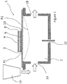
- Figure 1 schematically shows a cross section of part of a known droplet deposition head, hereinafter "printhead”.
- the printhead may be part of a known droplet deposition apparatus, hereinafter “printer”.
- the droplet deposition head comprises a die 1, such as a silicon die, having at least one pressure chamber 2, the pressure chamber having a membrane 3 with an actuator element 4 provided thereon to effect movement of the membrane 3 between a first position (depicted as P1), here shown as a neutral position, inwards into the pressure chamber to a second position (depicted as P2).
- P1 first position
- P2 second position
- the actuator element could also be arranged to deflect the membrane in a direction from P1 opposite to that of P2 (i.e. outwards of the pressure chamber).
- the pressure chamber 2 comprises a fluidic inlet port 14 for receiving fluid from a reservoir 16 arranged in fluidic communication with the pressure chamber 2.
- the pressure chamber 2 optionally comprises a fluidic outlet port 18 for recirculating any excess fluid in the pressure chamber 2 back to the reservoir 16 (or to another destination).
- the fluidic outlet port 18 is closed or no fluidic outlet port 18 is provided, then the fluidic inlet port 14 may merely replenish fluid that has been ejected from the pressure chamber 2 via nozzle 12.
- the fluidic inlet 14 and/or fluidic outlet port 18 may have a one-way valve.
- the reservoir 16 is merely depicted adjacent the pressure chamber 2 for illustrative purposes. However, it may be provided further upstream, or remote from the printhead using a series of pumps/valves to regulate the flow of fluid therefrom/thereto as appropriate.
- the actuator element 4 is a piezoelectric actuator element 4 whereby a piezoelectric material 6 is provided between a first electrode 8 and a second electrode 10 such that applying an electric field across the actuator element 4 causes the actuator element 4 to charge, such that it experiences a strain and deforms. It will be understood that the actuator element is not limited to being a piezoelectric actuator element, and any suitable actuator element 4 may be used as appropriate.
- the pressure chamber 2 is arranged in what is commonly referred to as a "roof mode" configuration, whereby deflection of the membrane 3 changes the volume, and, therefore the pressure, within the pressure chamber 2.
- a suitable deflection sequence to the membrane 3 such that sufficient positive pressure is generated within the pressure chamber 2 one or more droplets are ejected therefrom.
- Such droplet ejection from nozzle 12 may be achieved by applying drive pulses in the form of a voltage waveform to associated actuator element 4 e.g. to the first electrode 8, whilst maintaining the bottom electrode 10 at a reference potential such as ground potential.
- drive pulses in the form of a voltage waveform to associated actuator element 4 e.g. to the first electrode 8, whilst maintaining the bottom electrode 10 at a reference potential such as ground potential.
- the droplet deposition head may comprise a plurality of nozzles arranged in one or more nozzle arrays thereon.
- a common drive waveform comprising a sequence of one or more drive pulses may be selectively applied to plurality of actuator elements as a drive waveform for ejecting droplets from nozzles associated therewith.
- a drive waveform comprising a sequence of drive pulses may be generated on a per actuator element basis.
- Such a drive waveform may be generated, for example, by circuitry on the printhead.
- the ejection of the droplets may be timed so as to accurately land on a receiving medium (in conjunction with regulating the motion of a receiving medium, where necessary) within predetermined areas defined as pixels.
- These pixels are the desired position/location of the resulting dot on the receiving medium based on a rasterization of the image that is to be printed as derived from the print data.
- each pixel will be filled with either one or no droplet.
- greyscale levels may be added by printing two or more droplets into each pixel to alter the perceived colour density of the resulting pixel.
- the droplets landing within the same pixel will generally be referred to as sub-droplets.
- such sub-droplets may be ejected in rapid succession so as to merge before landing on the receiving medium as one droplet of a volume that is the sum of all sub-droplet volumes.
- the droplet Once landed on the receiving medium, the droplet will, in the following text, be referred to as a 'dot'; this dot will have a colour density defined by the droplet volume or the sum of all sub-droplet volumes.
- the drive pulses can therefore determine the greyscale level of a pixel.
- the die 1, and the associated features thereof may be fabricated using any suitable fabrication processes or techniques, such as, micro-electrical-mechanical systems (MEMS) processes.
- MEMS micro-electrical-mechanical systems
- pressure chamber 2 is depicted in Figure 1 , it will be understood that any number of pressure chambers may be arranged in a suitable configuration(s) therein.
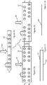
- Figures 2a-2e schematically show example configurations of nozzle arrays.
- the nozzles 12 are provided in a nozzle array in a single row, with adjacent nozzles in the row separated by a pitch (P) along the length of the die 1.
- the nozzles 12 are provided in a nozzle array, in two rows (R1, R2) in a non-staggered configuration relative to each other. Adjacent nozzles in the same row are separated by a pitch (P) along the length of the die 1 and adjacent rows are separated by a spacing (S) along the width of the die 1.
- Figure 2c schematically shows two lines 22 and 24 created on a receiving medium when all actuating elements of the nozzles of Figure 2b are driven at the same time.
- Figure 2d schematically shows a line created on a receiving medium when the nozzles of each row R1 and R2 of Figure 2b are caused to eject droplets with a suitable time delay between R1 and R2.
- the nozzles 12 are provided in a nozzle array, in two rows (R1, R2) in a staggered configuration relative to each other. As above, adjacent nozzles in the same row are separated by a pitch (P) along the length of the die 1 and adjacent rows are separated by a spacing (S) along the width of the die 1.
- the pitch (P) may vary along the length of the die e.g. when the nozzles towards the end of each row are separated by a pitch greater than P or less than P.
- crosstalk e.g. fluidic/mechanical/electrical
- crosstalk may occur when driving adjacent actuating elements, or actuating elements in close proximity, at substantially the same time, depending on the common fluid, mechanical or electrical path.
- Crosstalk may adversely affect the characteristics of droplets, thereby impacting the achievable print quality or the efficiency of the printer.
- Fluidic crosstalk may result from pressure waves between neighbouring pressure chambers
- mechanical crosstalk may be the result of insufficient stiffness of separating elements between pressure chambers (chamber walls, plenum walls); whilst electrical crosstalk may result from sharing electrical tracks between neighbouring actuator elements.
- the nozzles on each die 1 may be grouped together (e.g. in groups A, B, C, D, ...etc.), such that one or more nozzles of a first group (e.g. group A) may eject droplets as a result of a first waveform, whilst one or more nozzles of a second group (e.g. group B) eject droplets as a result of using a different waveform.
- a different waveform includes the first waveform following a temporal offset or delay (t).
- grouping adjacent nozzles in the same row in different groups e.g. A & B in Figure 2a
- ejecting droplets from the nozzles in the different groups with different waveforms e.g. different timings
- Grouping nozzles may also be advantageous when ejecting droplets from nozzles in different rows.
- droplets ejected from the different groups of nozzles A, B, C and D may generate a desired dot pattern on the receiving medium, whilst reducing crosstalk.
- droplet ejection may be controlled to generate desired features, whilst reducing electrical, mechanical and/or fluidic crosstalk.
- the printer In order to generate the different waveforms and eject droplets from the nozzles at the correct timings, the printer comprises various hardware and software components.
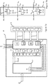
- Figure 3 shows a printer 30 which comprises a printer controller 32 and further comprises a printhead 34 according to an embodiment.
- printer controller 32 which comprises a printer controller 32 and further comprises a printhead 34 according to an embodiment.
- printhead 34 according to an embodiment.
- Like reference numerals used previously will be used to describe identical or similar features as appropriate.
- the printhead 34 comprises a printhead controller 36 and a die 1, the die 1 having one or more pressure chambers (not shown) with associated features (e.g. nozzle, actuators element etc.) as previously described.
- the printer controller 32 comprises hardware and software components configured to regulate the functionality of the printer 30.
- the printer controller 32 includes communication circuitry (not shown) for transmitting/receiving communications to/from one or more internal/external sources, such as a host computer (not shown), printhead 34 and/or a media encoder 40.
- communication circuitry for transmitting/receiving communications to/from one or more internal/external sources, such as a host computer (not shown), printhead 34 and/or a media encoder 40.
- the communication circuitry may comprise an external and or internal interface unit for receiving print data transmitted from the host computer and may include a serial interface such as USB (Universal Serial Bus), IEEE1394, Ethernet, wireless network, or a parallel interface.
- a serial interface such as USB (Universal Serial Bus), IEEE1394, Ethernet, wireless network, or a parallel interface.
- the communication circuitry may comprise an internal interface unit for transmitting data between the printer controller 32 and printhead controller 36, and may include a serial interface such as USB (Universal Serial Bus), IEEE1394, Ethernet, wireless network, or a parallel interface.
- a serial interface such as USB (Universal Serial Bus), IEEE1394, Ethernet, wireless network, or a parallel interface.
- print data 38 is transmitted to the printer controller 32, whereby the print data 38 relates to the desired characteristics of a dot to be created on a receiving medium (e.g. position, density, colour etc.).
- the print data 38 may define the characteristics of the droplets required to be ejected from a particular nozzle in order to fill a pixel and create a dot on a receiving medium or, as the case may be, to not fill a pixel with no droplet being ejected.
- the printer controller 32 processes the print data 38 and generates a printhead data stream 39 in response thereto, whereby the printhead data stream 39 comprises instruction code for different groups of nozzles of the printhead 34, and, in particular, instruction code denoting a specific function/instruction for nozzles designated in a particular group, e.g. indicating how the individual nozzles of the particular group should be controlled to fill the respective pixels (i.e. to eject one or more droplets or to not eject droplets as the case may be).
- the printhead data stream 39 also comprises instruction code indicating when a particular group should be "fired” i.e. indicating when the actuating elements associated with the nozzles designated in the particular group should be driven or not driven so as to control the nozzles as appropriate.
- A-D groups of nozzles
- the printhead 34 e.g. arranged in one or more rows.
- any number of groups may be used.
- the printhead data stream 39 is transmitted to the printhead controller 36, and processed by circuitry thereat.
- the instruction code indicating when a group should be fired is included in the printhead data stream 39 as a reserved code or data packet(s), hereinafter "fire code", whereby the fire code is identified by the printhead controller 36 as a timing signal for firing an associated group.
- the fire code is generated independently of the instruction code denoting a specific function/instruction for nozzles.
- media encoder 40 is provided in communication with the printer controller 32, whereby the media encoder 40 generates data relating to characteristics of a receiving medium (not shown) onto which droplets are to be ejected. Such data may relate to the velocity/acceleration of the receiving medium moving relative to the printhead 34 or to the velocity/acceleration of the printhead 34 moving relative to the receiving medium.
- the media encoder 40 transmits the data as an input, hereinafter 'ME input' 42, to the printer controller 32.
- the printer controller 32 processes the ME input 42 to determine at what point in time a group of nozzles should be fired in order to accurately fill pixels on the receiving medium.
- the media encoder 40 may provide an ME input every (T) based on the relative movement between the printhead 34 and receiving medium. If the velocity of the receiving medium changes (e.g. slows down to give e.g. (T+ ⁇ m) or speeds up to give (T- ⁇ m)) the media encoder 40 will update the ME input accordingly.
- the printer controller 32 also transmits waveform data 44 to the printhead controller 36.
- the waveform data 44 may comprise one or more drive waveforms, whereby each drive waveform may be applied as drive pulses to drive the actuating elements associated with the nozzles of a particular group.
- the waveform data 44 may comprise signals which the printhead controller 36 processes to generate drive pulses on a per actuator element, or per group, basis.
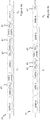
- Figures 4a and 4b illustratively show an example printhead data stream 39 according to an embodiment, whereby the printhead data stream 39 comprises data blocks for the different groups of nozzles, whereby a data block comprises instruction code in the form of drive data denoting how the individual nozzles of a particular group should be controlled during a droplet period D i (shown as (D i ), where 'i' is an integer and denotes a specific droplet period for which the nozzles are to be controlled).
- DATA A comprises drive data for Group A
- DATA B comprises drive data for Group B
- DATA C comprises drive data for Group C
- DATA D comprises drive data for Group D.
- fire codes 47 (depicted as (FC x ), where 'x' denotes the particular group), are also depicted as being included in the printhead data stream 39.
- FC A indicates when Group A should be fired for droplet period D 1 ;
- FC B indicates when Group B should be fired for D 1 ;
- FCc indicates when Group C should be fired for D 1 ;
- FC D indicates when Group D should be fired for D 1 .
- the fire code for a particular group is generated independent of the data blocks comprising the instruction code, whereby, for example, the fire codes are generated independent of the data blocks for the respective groups and independent of the data blocks for other groups in the printhead data stream 39, such that fire codes can be inserted anywhere within the printhead data stream.
- the fire code FC x may directly follow the data block for that particular group.
- the fire code FC x may be positioned elsewhere in the printhead data stream 39 (i.e. indirectly follow the data block for that particular group).
- the fire code FC x may be inserted in the printhead data stream 39 so as to interrupt a subsequent data block (DATA x+1), or it may be inserted in the printhead data stream 39 between two subsequent data blocks for different groups (e.g. between DATA x+1 and DATA x+2).
- FC A indirectly follows DATA A by being inserted so as to interrupt DATA B;
- FC B indirectly follows DATA B by being inserted between DATA C and DATA D;
- FCc indirectly follows DATA C by being inserted so as to interrupt DATA D, whilst FC D immediately follows DATA D.
- FC x fire codes
- the printhead data stream can be transmitted to the printhead controller faster in comparison to having to wait for a data block to complete, such that the timing accuracy for firing the groups can be increased. Therefore, the droplet deposition head may print with an increased drop placement accuracy, for example even when accelerating or decelerating relative to the receiving medium. Such functionality is advantageous as the print speed increases.
- providing fire codes for the different groups means the different groups can be fired independently of each other, and therefore the respective nozzles of one group may be controlled independently of nozzles in a different group.
- controlling nozzles of the different groups with carefully chosen time delays provides for a reduction in crosstalk, which in turn provides for improvements in print quality.
- FIGS. 4a and 4b depict the data blocks and fire codes as having a 1:1 mapping per droplet period i.e. whereby a fire code (FC x ) is generated every time a data block (DATA x) is generated, this is not always the case.
- a data block (DATA x) will not be generated for every droplet period Di-i nor will a fire code (FC x ) be generated for every droplet period Di-i.
- one data block may be generated for a particular group of nozzles for a first droplet period D 1 , whilst a plurality of fire codes may be provided for the particular group for the first droplet period D 1 and/or for one or more subsequent droplet periods D 2 - D i .
- FIG. 5 schematically shows components of the printer controller 32 in greater detail. Like reference numerals used previously will be used to describe identical or similar features as appropriate.
- the printhead controller 32 comprises processing circuitry 46, configured to process data (e.g. print data 38, ME input 42, operational data 56, programs or instructions etc.) and to generate output signals in response to the processed data.
- data e.g. print data 38, ME input 42, operational data 56, programs or instructions etc.
- the processing circuitry 46 may, for example, comprise a field programmable gate array (FPGA), system on chip (SoC) device, microprocessor device, microcontroller or one or more integrated circuits.
- FPGA field programmable gate array
- SoC system on chip
- the printhead controller 32 also comprises storage circuitry 48 for storing data.
- the storage circuitry 48 may comprise volatile memory such as random access memory (RAM), for use as temporary memory whilst the printhead controller 32 is in an operational state.
- RAM random access memory
- the storage circuitry 48 may comprise non-volatile memory such as flash, read only memory (ROM) or electrically erasable programmable ROM (EEPROM), for storing data whilst the printhead controller 32 is in an operational or non-operational state (e.g. powered down or power saving state).
- non-volatile memory such as flash, read only memory (ROM) or electrically erasable programmable ROM (EEPROM), for storing data whilst the printhead controller 32 is in an operational or non-operational state (e.g. powered down or power saving state).
- ROM read only memory
- EEPROM electrically erasable programmable ROM
- print data 38 is received at the printer controller 32, and may be stored in a buffer (not shown) in the storage circuitry 48 whilst awaiting processing.
- the processing circuitry 46 comprises print data encoder circuitry 51, hereinafter 'PDE circuitry' 51.
- the PDE circuitry 51 generates encoded drive data based on or in response to processing the print data 38 (e.g. from a buffer), whereby the encoded drive data is included in the printhead data stream 39.
- the encoded drive data may be created using any suitable encoding scheme (e.g. 4b/5b, 4b/6b encoding, 6b/8b encoding, 8b/10b encoding, 64b/66b encoding, Eight-to-fourteen modulation etc.)
- any suitable encoding scheme e.g. 4b/5b, 4b/6b encoding, 6b/8b encoding, 8b/10b encoding, 64b/66b encoding, Eight-to-fourteen modulation etc.
- the processing circuitry 46 further comprises media encoder circuitry 52, hereinafter'ME circuitry', which processes the ME input 42 and generates a media signal 54 in response thereto.
- media encoder circuitry 52 hereinafter'ME circuitry'
- the ME circuitry 52 may also generate the media signal 54 in response to additional data, such as operational data 56 relating to the desired operation of the printer (e.g. desired resolution (e.g. 1200dpi), desired frequency (e.g. 70kHz) - it will be understood these figures are for illustrative purposes only).
- operational data 56 relating to the desired operation of the printer (e.g. desired resolution (e.g. 1200dpi), desired frequency (e.g. 70kHz) - it will be understood these figures are for illustrative purposes only).
- the media signal 54 is used by the PDE circuitry 51 to determine when a fire code (FC x ) for a particular group should be included in the printhead data stream 39 such that a corresponding group can be fired at the correct time during a specific droplet period.
- FC x fire code
- the printhead data stream 39 comprises data blocks (DATA A - DATA D) provided for the groups of nozzles on the die, each data block having encoded drive data denoting how the individual nozzles of a particular group should be controlled.
- the encoded drive data comprises a plurality of data packets 57 each comprising an m-bit code (where m is an integer), which in the present example, is a drive code symbol to indicate how a particular nozzle should be controlled.
- the data packets 57 comprise 10-bit drive code symbols mapped from 8-bit code symbols based on or responsive to the print data.
- alternative encoding schemes may also be used.
- the drive code symbols comprise (D) and (ND), whereby a (D) symbol indicates that one or more droplets should be ejected from a particular nozzle, whilst an (ND) symbol indicates that a droplet should not be ejected from a particular nozzle.
- each data packet 57 is associated with a particular nozzle, as indicated by N XL in figure 6 , (where, as above, 'x' denotes the particular group & where L is an integer, indicative of the nozzle's position/designation within the group).
- the drive code symbols included in the data packets 57 may also comprise an identifier for the nozzle indicative of the nozzle's position/designation within the group.
- groups may comprise any number of nozzles, and different groups may have different numbers of nozzles designated therein.
- the printhead data stream 39 further comprises reserved code or data packets having k-bit control symbols (where 'k' is an integer) which designate or denote a defined instruction e.g. fire code (FC x ) 47, start of data block (SoB x ) 59, or end of data block (not shown).
- a reserved code comprises a unique code in the data stream.
- the k-bit control symbols may be inserted in the printhead data stream 39 by the PDE circuitry when required.
- the fire code (FC x ) control symbols may be inserted within the printhead data stream 39 in response to the media signal 54.
- the k-bit control symbols are encoded using the same encoding scheme used to encode the drive code symbols.
- the ability to insert fire codes into the printhead data stream independently of the drive data provides for increased print speeds and/or higher image quality because there is no requirement for the printer controller to wait until a data block is completed before inserting the fire code in the printhead data stream and, therefore, the delay between generating the fire code and transmitting it to the printhead controller is minimised.
- the printer controller 32 transmits the printhead data stream 39 to the printhead controller using any suitable communications protocol and/or signalling standard e.g. 8b/10b encoding on low voltage differential signalling (LVDS), a serial communications protocol, etc.
- any suitable communications protocol and/or signalling standard e.g. 8b/10b encoding on low voltage differential signalling (LVDS), a serial communications protocol, etc.
- a clock signal may be transmitted to printhead controller 36 for use in the decoding process.
- an LVDS clock signal may be transmitted to the printhead controller 36 alongside the printhead data stream 39 or the clock signal (e.g. digital clock signal) may be recovered from the printhead data stream 39.
- the printhead data stream 39 comprising the data blocks and fire codes may be transmitted along a single communications channel, which, depending on the protocol and/or standard used, may comprise a single conductor or pair of conductors (e.g. wires, pins). However, any suitable communications channel may be provided.
- the printer controller 32 also transmits waveform data 44 to the printhead controller 36 using any suitable communications protocol and/or signalling standard.
- the waveform data 44 comprises a common drive waveform for each group, whereby, as depicted, the printer controller 32 comprises four waveform generators 58a-58d, each configured to generate a common drive waveform in response to a waveform control signal 60a-60d.
- Each waveform control signal 60a-60d comprises a logic output which is fed to a respective digital-to-analog converter (DAC) (not shown), whereby an analog output from the DAC may be used as an input to an amplifier for generating the respective common drive waveform 44a-44d.
- DAC digital-to-analog converter
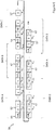
- FIG 7a schematically shows components of the printhead controller 36 in greater detail. Like reference numerals used previously will be used to describe identical or similar features as appropriate.
- the printhead controller 36 comprises various hardware & software components for communicating with the printer controller (not shown in Figure 7a ) and driving the actuating elements to control nozzles associated therewith in an appropriate manner.
- the printhead controller 36 may comprise one or more application specific integrated circuits (ASIC) or other suitable hardware/software components.
- ASIC application specific integrated circuits
- the printhead controller 36 comprises decoder circuitry 62, which receives the printhead data steam 39 from the printer controller (not shown in Figure 7a ), decodes the printhead data stream 39, and generates one or more outputs for controlling the nozzles of the respective groups.
- one output is nozzle data stream 64a-d, which comprises decoded drive data, whereby the nozzle data stream 64a-d may define how each nozzle of a particular group is to be controlled.
- a further output is fire signal 66, which, in the present example, is illustratively depicted as a different fire signal for each respective group A-D.
- the decoder circuitry 62 decodes the printhead data stream 39 in accordance with the scheme used to generate the encoded print data as previously described and outputs the nozzle data stream 64a-d and fire signal 66a-d accordingly.
- the printhead controller 36 further comprises storage circuitry 68, which, in the present example, comprises four shift register arrays 68a-68d, each array having one or more registers arranged to temporarily store data packets of the nozzle data stream 64 for one of the respective groups (A-D).
- storage circuitry 68 which, in the present example, comprises four shift register arrays 68a-68d, each array having one or more registers arranged to temporarily store data packets of the nozzle data stream 64 for one of the respective groups (A-D).
- the data packets in the nozzle data stream 64 are loaded into the appropriate shift register arrays e.g. whereby, for example, the SoB x control code in a decoded data block defines the appropriate shift register array into which the next L decoded data packets following the SoB x are loaded, whilst the specific positioning of the data packet following the SoB x may define the particular shift register in the register array into which that packet is loaded into.
- the drive code symbol in a particular data packet may define the specific register in the register array into which that particular data packet is loaded, as identified by, for example, the decoder circuitry 62.
- the printhead controller 36 further comprises switch logic 70 for switching the waveform data 44a-44d onto the nozzles of the different groups (A-D) in response to the drive code symbols in the different packets and the fire signal 66.
- the switch logic 70 may comprise an array of switches 74a-d for the respective groups (A-D), each switch 76 in an array 74a-d associated with a particular shift register and a particular nozzle, and the state of which is controlled (open/closed) by a switch controller 65 which may comprise any suitable logic or component.
- the decoder circuitry 62 On decoding the printhead data stream 39 and identifying a fire code FC x for a particular group (A-D), the decoder circuitry 62 outputs a fire signal 66 for the particular group (A-D), whereby the decoded data packets are output from the corresponding shift registers and used as inputs 64 to switch controller 65 along with fire signal 66, whereby an output 67 from switch controller 65 is used to control the state of an associated switch 76 in accordance with drive code symbols in the decoded drive data for that particular nozzle.
- the switch controller 65 when the switch controller 65 receives a data packet comprising an ND symbol and a fire signal, the switch controller 65 opens the switch 76 such that no drive pulse is applied to the actuator element of the associated nozzle. Therefore, no droplet will be ejected from that nozzle for that droplet period. This is depicted for Nozzle N A100 in Figure 7b .
- Ejection of droplets from nozzles N A3 -N A99 for the droplet period may be controlled by the switch controller 65 dependent on the respective decoded drive data and fire signal in the same manner as described above for N A1 , N A2 & N A100 .
- the switches 76 may comprise one or more transistors arranged in a suitable configuration, such as a pass gate configuration.
- the data blocks there is no requirement for the data blocks to have a 1:1 mapping with the fire codes, whereby, in embodiments, when the data packets of the respective data blocks are loaded into the appropriate shift register arrays, those data packets may be retained within the shift registers for two or more droplet periods, such that, when a fire code is identified, the nozzles of a particular group may be controlled in response to data packets previously loaded in the shift registers.
- the PDE circuitry (not shown in Figure 7a ) is not required to encode new print data into the printhead data stream 39 for each droplet period and the PDE is only required to generate fire codes corresponding to when the groups should be fired.
- processing efficiency may be increased both at the printer controller and printhead controller in comparison to repeatedly encoding the same print data for the one or more droplet periods.
- the amount of data in the printhead data stream 39 may also be reduced, and, therefore, reduces the burden placed on the communications channel bandwidth in high resolution applications.
- idle symbols may be provided between the fire codes so as to provide spacing in the encoded printhead data stream (e.g. between fire codes), whereby the idle symbols do not cause the data packets to be overwritten in the registers.
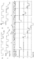
- Figure 8a schematically shows example drive waveforms (A-D) 44a-44d
- Figure 8b schematically shows a printhead data stream 39
- Figure 8c schematically shows the waveforms (A-D) as they would be applied to the different nozzles N XL over two droplet periods D 1 and D 2 in response to printhead data stream 39 when decoded at the printhead controller.
- the nozzles N XL for a particular group will be controlled with the waveforms (A-D) in response to the drive code symbols (e.g. D & ND) in the drive data, at a time as defined by the decoded fire codes FC A - FC D .
- the drive code symbols e.g. D & ND
- waveforms A & C are used to drive actuator elements of adjacent nozzles on the same row (R1), whilst waveforms B & D are used to drive actuator elements of adjacent nozzles on the same row (R2).
- waveforms A-D are similar to each other but a different delay (a1-a3) is provided between the respective waveforms. It will be appreciated that the waveforms and delays depicted in Figures 8a are illustrative only, and any waveform and/or delay may be provided for a particular group for any droplet period.
- the specific delay between waveforms for ejecting droplets from nozzles in different rows may be selected based on or responsive to different factors, such as: the velocity of the receiving medium relative to the printhead, and/or the operational frequency of the printhead.
- the specific delay between the waveforms for ejecting droplets from nozzles in the same row may be selected to minimise the crosstalk between adjacent nozzles, which, as above, may affect the specific placement and/or quality of droplets on the receiving medium.
- This specific delay may be adjusted to account for variations in the speed of the receiving medium to provide for correct placement of droplets from nozzles in the same row of the receiving medium.
- the fire code there is no specific requirement for the fire code to be in a fixed order or fixed position within the data stream, and it is possible to insert fire codes into the printhead data stream without having to wait for a particular data block to complete before insertion therein.
- the ability to insert fire codes into the printhead data stream before a particular data block completes provides for increased print speeds in comparison to having to wait for a data block to complete until inserting a fire code.
- Such functionality becomes increasingly advantageous as the print frequency (i.e. the speed of printing) increases.
- the fire codes are associated with respective groups of nozzles, and the groups can be defined to designate one or more nozzles in one or more rows, it is possible to control ejection of droplets from single or multiple rows of nozzles as appropriate dependent on the specific application.
- crosstalk e.g. mechanical, fluidic, electrical
- the waveforms A-D can be selectively applied to the respective groups, and the nozzles of the respective groups can be controlled by the switch logic over consecutive droplet periods, it is possible to fill pixels with the appropriate amount of droplets over one or more droplet periods as required by the print data.
- the waveform data may alternatively be generated at the printer controller, printhead controller or may be generated remote from the printer itself.
- the waveform data may comprise a waveform common to all nozzles of a particular group, but instead the waveform data may comprise a waveform generated on a per-nozzle basis at the printer controller, printhead controller or remote from the printer itself.
- waveforms are not limited to the shape depicted in Figures 8a , and any suitable shapes may be used as drive pulses.
- a trapezoidal or sinusoidal drive pulse may be used.
- characteristics of the drive pulses may be changed as appropriate depending on a particular application. Such characteristics include but are not limited to: amplitude, pulse width, slew rates etc.
- the firing pulse may be followed by one or more non-ejecting pulses (not shown) which are used to generate pressure waves which interfere with the pressure waves caused by the firing pulse.
- the printhead data stream may comprise idle symbols therewithin.
- the present techniques may be realized in the form of a data carrier having functional data thereon, said functional data comprising functional computer data structures to, when loaded into a computer system or network and operated upon thereby, enable said computer system to perform all the steps of the method.
- a droplet deposition head may eject droplets of fluid that may travel to a sheet of paper or card, or to another receiving medium, such as textile or foil or shaped articles (e.g. cans, bottles etc.), to form an image, as is the case in inkjet printing applications, where the droplet deposition head may be an inkjet printhead or, more particularly, a drop-on-demand inkjet printhead.
- Web presses and cut sheet presses have demanding data rates.
- the resolution and receiving medium speed are both high [600 dpi and 800 fpm (160 ips or 4m/s) with 3 grey levels].
- Two sets of printheads are needed in the down web direction to fill all the pixels in the direction of movement of the receiving medium.
- Another application is wide format graphics where a scanning printhead moving as fast as 70 inch/sec (1.7m/s) jets ultra-violet (UV) curable, solvent, or aqueous inks with multiple grey levels.
- a scanning printhead moving as fast as 70 inch/sec (1.7m/s) jets ultra-violet (UV) curable, solvent, or aqueous inks with multiple grey levels.
- UV ultra-violet
- Droplet deposition heads suitable for such fluids may be generally similar in construction to printheads, with some adaptations made to handle the specific fluid in question.
- Droplet deposition heads as described in the following disclosure may be drop-on-demand droplet deposition heads.
- the pattern of droplets ejected varies in dependence upon the data provided to the head.
Landscapes
- Particle Formation And Scattering Control In Inkjet Printers (AREA)
- Ink Jet (AREA)
- Coating Apparatus (AREA)
Claims (15)
- Steuerung (32) zum Steuern von zwei oder mehr Düsengruppen in einem Array, wobei die Steuerung konfiguriert ist zum:Encodieren von Datenblöcken zu einem Datenstrom (39), wobei jeder Datenblock angibt, wie eine jeweilige Düsengruppe für eine Tropfchenperiode zu steuern ist; undEncodieren von Fire-Codes (47) zu dem Datenstrom (39), wobei jeder Fire-Code (47) ein reservierter Code ist, der angibt, wann eine jeweilige Düsengruppe gemäß dem Datenblock für die Tröpfchenperiode zu steuern ist;wobei der Datenblock dem Fire-Code (47) für die jeweilige Düsengruppe im Datenstrom (39) vorangeht und wobei die Fire-Codes unabhängig von den Datenblöcken erzeugt werden.
- Steuerung nach Anspruch 1, wobei der Fire-Code (47) unmittelbar auf den Datenblock für die jeweilige Gruppe folgt.
- Steuerung (32) nach Anspruch 1, ferner konfiguriert zum Einfügen des Fire-Code (47) zwischen zwei nachfolgende Datenblöcke in dem Datenstrom (39);
oder ferner konfiguriert zum Einfügen des Fire-Code (47), um einen nachfolgenden Datenblock im Datenstrom (39) zu unterbrechen. - Steuerung (32) nach einem vorherigen Anspruch, die ferner zum Empfangen eines Eingangs (42) von einem Medien-Encoder (40) konfiguriert ist und ferner Folgendes umfasst:eine Medien-Encoder-Schaltung (52), konfiguriert zum Erzeugen eines Mediensignals (54) als Reaktion auf den Eingang (42) von dem Medien-Encoder (40);wobei die Steuerung (32) ferner zum Encodieren der Datenblöcke im Datenstrom (39) als Reaktion auf Druckdaten und zum Einfügen der Fire-Codes in den Datenstrom (39) als Reaktion auf das Mediensignal (54) konfiguriert ist.
- Steuerung (32) nach einem vorherigen Anspruch, wobei die Datenblöcke und Fire-Codes für die jeweiligen Gruppen mit einem 1:1 Mapping für jede Tröpfchenperiode encodiert werden.
- Steuerung (32) nach einem vorherigen Anspruch, wobei jeder Datenblock ein Steuersymbol umfasst, das einen Start des Datenblocks oder ein Ende des Datenblocks angibt.
- Steuerung (36) zum Steuern von Düsen in einem Array, wobei die Steuerung Folgendes umfasst:Schaltlogik (70), konfiguriert zum Anlegen von Ansteuerungsimpulsen (72) an die Düsen; undSchaltung (62), konfiguriert zum:Decodieren eines ersten Datenstroms (39), der an der Steuerung empfangen wird;Identifizieren, im ersten Datenstrom (39), von Datenblöcken für jeweilige Düsengruppen, und Erzeugen eines zweiten Datenstroms (64) als Reaktion darauf, wobei der zweite Datenstrom (64) erste und zweite Ansteuerungsdaten (64a, 64b) zum Steuern der Schaltlogik für eine Tröpfchenperiode umfasst; undIdentifizieren, im ersten Datenstrom (39), von reservierten Codes, die angeben, wann die jeweiligen Düsengruppen gemäß den Datenblöcken gesteuert werden sollen, und Erzeugen von ersten und zweiten Fire-Signalen (66a, 66b) zum Steuern der Schaltlogik (70) als Reaktion auf die reservierten Codes;wobei die Schaltung (62) ferner für eine erste Tröpfchenperiode konfiguriert ist zum:Steuern der Schaltlogik (70) für eine erste Gruppe der Düsen als Reaktion auf die ersten Ansteuerungsdaten (64a) und das erste Fire-Signal (66a); undunabhängiges Steuern der Schaltlogik (70) für eine zweite Düsengruppe als Reaktion auf die zweiten Ansteuerungsdaten (64b) und das zweite Fire-Signal (66b).
- Steuerung (36) nach Anspruch 7, wobei der zweite Datenstrom (64) ferner dritte und vierte Ansteuerungsdaten (64c, 64d) umfasst und die Schaltung (62) ferner, für eine zweite Tröpfchenperiode, konfiguriert ist zum:Erzeugen von dritten und vierten Fire-Signalen (66c, 66d) vom ersten Datenstrom (39);Steuern der Schaltlogik für die erste Düsengruppe als Reaktion auf die dritten Ansteuerungsdaten (64c) und das dritte Fire-Signal (66c); undunabhängiges Steuern der Schaltlogik für die zweite Düsengruppe als Reaktion auf die vierten Ansteuerungsdaten (64d) und das vierte Fire-Signal (66d).
- Steuerung (36) nach Anspruch 7, wobei die Schaltung (62) ferner, für eine zweite Tröpfchenperiode, konfiguriert ist zum:Erzeugen von dritten und vierten Fire-Signalen (66c, 66d) vom ersten Datenstrom (39);Steuern der Schaltlogik für die erste Düsengruppe als Reaktion auf die ersten Ansteuerungsdaten (64a) und das dritte Fire-Signal (66c); undunabhängiges Steuern der Schaltlogik für die zweite Düsengruppe als Reaktion auf die zweiten Ansteuerungsdaten (64b) und das vierte Fire-Signal (66d).
- Steuerung (36) nach einem der Ansprüche 7 bis 9, die ferner Folgendes umfasst:
eine Speicherschaltung (68), konfiguriert zum Speichern der Ansteuerungsdaten und zum Ausgeben der Ansteuerungsdaten an die Schaltlogik (70). - Tröpfchenabsetzvorrichtung (30), die die Steuerung (32) nach einem der Ansprüche 1 bis 6 und/oder die Steuerung (36) nach einem der Ansprüche 7 bis 10 umfasst.
- Verfahren zum Steuern von zwei oder mehr Düsengruppen in einem Array, wobei das Verfahren Folgendes beinhaltet:Erzeugen, an einer Steuerung (32), eines Datenstroms (39), der encodierte Datenblöcke umfasst, wobei jeder encodierte Datenblock angibt, wie eine jeweilige Düsengruppe für eine Tröpfchenperiode gesteuert werden soll; undEncodieren, an der Steuerung (32), von Fire-Codes (47) zu dem Datenstrom (39), wobei jeder Fire-Code (47) ein reservierter Code ist, der angibt, wann eine jeweilige Düsengruppe gemäß dem encodierten Datenblock für die Tröpfchenperiode gesteuert werden soll, und wobei der encodierte Datenblock dem Fire-Code (47) für die jeweilige Düsengruppe in dem Datenstrom (39) vorangeht.
- Verfahren zum Steuern von zwei oder mehr Düsengruppen in einem Array, wobei das Verfahren Folgendes beinhaltet:Decodieren, an einer Steuerung (36), eines ersten Datenstroms (39);Identifizieren, im ersten Datenstrom (39), von Datenblöcken für jeweilige Düsengruppen;Identifizieren, im ersten Datenstrom (39), von reservierten Codes, die angeben, wann die jeweiligen Düsengruppen gemäß den Datenblöcken gesteuert werden sollen;Erzeugen, als Reaktion auf den ersten Datenstrom (39), von ersten und zweiten Fire-Signalen (66a, 66b) und einem zweiten Datenstrom, umfassend erste und zweite Ansteuerungsdaten (64a, 64b) für jeweilige Düsengruppen;Steuern von Schaltlogik für eine erste Tröpfchenperiode zum Anlegen von Ansteuerungsimpulsen an eine erste Düsengruppe als Reaktion auf die ersten Ansteuerungsdaten (64a) und das erste Fire-Signal (66a); undunabhängiges Steuern von Schaltlogik für die erste Tröpfchenperiode zum Anlegen von Ansteuerungsimpulsen an eine zweite Gruppe von Düsen als Reaktion auf die zweiten Ansteuerungsdaten (64b) und das zweite Fire-Signal (66b).
- Verfahren nach Anspruch 13, das ferner Folgendes beinhaltet:Erzeugen, als Reaktion auf den ersten Datenstrom (39), von dritten und vierten Fire-Signalen (66c, 66d), wobei der zweite Datenstrom (64) ferner dritte und vierte Ansteuerungsdaten (64c, 64d) umfasst;Steuern von Schaltlogik für eine zweite Tröpfchenperiode zum Anlegen von Ansteuerungsimpulsen an die erste Düsengruppe als Reaktion auf die dritten Ansteuerungsdaten (64c) und das dritte Fire-Signal (66c); undunabhängiges Steuern von Schaltlogik für die zweite Tröpfchenperiode zum Anlegen von Ansteuerungsimpulsen an die zweite Düsengruppe als Reaktion auf die vierten Ansteuerungsdaten (64d) und das vierte Fire-Signal (66d).
- Verfahren nach Anspruch 13, das ferner Folgendes beinhaltet:Erzeugen, als Reaktion auf den ersten Datenstrom (39), von dritten und vierten Fire-Signalen (66c, 66d);Steuern von Schaltlogik für eine zweite Tröpfchenperiode zum Anlegen von Ansteuerungsimpulsen an die erste Düsengruppe als Reaktion auf die ersten Ansteuerungsdaten (64a) und das dritte Fire-Signal (66c); undunabhängiges Steuern von Schaltlogik für die zweite Tröpfchenperiode zum Anlegen von Ansteuerungsimpulsen an die zweite Düsengruppe als Reaktion auf die zweiten Ansteuerungsdaten (64b) und das vierte Fire-Signal (66d).
Applications Claiming Priority (2)
| Application Number | Priority Date | Filing Date | Title |
|---|---|---|---|
| GB1605372.0A GB2548859B (en) | 2016-03-30 | 2016-03-30 | A droplet deposition apparatus |
| PCT/GB2017/050882 WO2017168149A1 (en) | 2016-03-30 | 2017-03-29 | A droplet deposition apparatus and controller therefor |
Publications (2)
| Publication Number | Publication Date |
|---|---|
| EP3436273A1 EP3436273A1 (de) | 2019-02-06 |
| EP3436273B1 true EP3436273B1 (de) | 2020-05-27 |
Family
ID=56027615
Family Applications (1)
| Application Number | Title | Priority Date | Filing Date |
|---|---|---|---|
| EP17715981.1A Active EP3436273B1 (de) | 2016-03-30 | 2017-03-29 | Tröpfchenabscheidungsvorrichtung und steuergerät dafür |
Country Status (9)
| Country | Link |
|---|---|
| US (1) | US11001057B2 (de) |
| EP (1) | EP3436273B1 (de) |
| JP (1) | JP7012021B2 (de) |
| CN (1) | CN108883635B (de) |
| GB (1) | GB2548859B (de) |
| IL (1) | IL261541A (de) |
| MX (1) | MX2018011736A (de) |
| TW (1) | TW201801943A (de) |
| WO (1) | WO2017168149A1 (de) |
Families Citing this family (6)
| Publication number | Priority date | Publication date | Assignee | Title |
|---|---|---|---|---|
| BR112021015008A2 (pt) | 2019-02-06 | 2021-10-05 | Hewlett-Packard Development Company, L.P. | Matriz para cabeça de impressão |
| GB2582966A (en) * | 2019-04-11 | 2020-10-14 | Xaar Technology Ltd | Methods, apparatus and control systems for droplet deposition apparatus |
| JP7476859B2 (ja) | 2021-03-30 | 2024-05-01 | ブラザー工業株式会社 | ヘッド及び印刷装置 |
| JP7435522B2 (ja) | 2021-03-30 | 2024-02-21 | ブラザー工業株式会社 | 液適吐出装置及びヘッドの制御方法 |
| EP4067088A1 (de) * | 2021-03-30 | 2022-10-05 | Brother Kogyo Kabushiki Kaisha | Flüssigkeitsausstosskopf |
| JP7476861B2 (ja) | 2021-09-30 | 2024-05-01 | ブラザー工業株式会社 | 印刷装置 |
Family Cites Families (18)
| Publication number | Priority date | Publication date | Assignee | Title |
|---|---|---|---|---|
| US5142296A (en) * | 1990-11-09 | 1992-08-25 | Dataproducts Corporation | Ink jet nozzle crosstalk suppression |
| US5754193A (en) | 1995-01-09 | 1998-05-19 | Xerox Corporation | Thermal ink jet printhead with reduced power bus voltage drop differential |
| JPH08258292A (ja) | 1995-03-20 | 1996-10-08 | Canon Inc | 記録装置 |
| JP3352331B2 (ja) | 1996-07-31 | 2002-12-03 | キヤノン株式会社 | 記録ヘッド用基板、記録ヘッド、ヘッドカートリッジ及びその記録ヘッドを用いた記録装置 |
| US6828995B1 (en) | 1999-05-14 | 2004-12-07 | Canon Kabushiki Kaisha | Printing apparatus and printing method |
| KR20000075358A (ko) * | 1999-05-27 | 2000-12-15 | 윤종용 | 이동통신시스템에서 라디오링크프로토콜에 따른 가변길이의 데이터 송수신 장치 및 방법 |
| DE60030893D1 (de) | 2000-06-30 | 2006-11-02 | Silverbrook Res Pty Ltd | Steuerung der ausstosszeiten der druckkopfdüsen |
| JP3944712B2 (ja) * | 2001-04-17 | 2007-07-18 | セイコーエプソン株式会社 | インクジェット式プリンタ |
| JP4579485B2 (ja) * | 2002-06-24 | 2010-11-10 | セイコーエプソン株式会社 | 複数の印刷ヘッドを有する印刷装置 |
| US20080205957A1 (en) | 2007-02-23 | 2008-08-28 | Samsung Electronics Co., Ltd. | Printer head chip for detecting error, printer head including the printer head chip, image forming apparatus including the same and method of controlling the same |
| JP5072578B2 (ja) * | 2007-12-21 | 2012-11-14 | キヤノン株式会社 | ヘッド素子基板、記録ヘッド、及び記録装置 |
| JP2010120328A (ja) | 2008-11-21 | 2010-06-03 | Seiko Epson Corp | 画像形成装置 |
| JP5310337B2 (ja) * | 2009-07-15 | 2013-10-09 | セイコーエプソン株式会社 | 流体噴射装置、流体噴射装置における流体噴射ヘッド制御方法及び流体噴射ヘッド用の駆動波形生成装置 |
| WO2011093889A1 (en) | 2010-01-29 | 2011-08-04 | Hewlett-Packard Development Company, L.P. | Crosstalk reduction in piezo printhead |
| JP2012196902A (ja) | 2011-03-22 | 2012-10-18 | Seiko Epson Corp | 液体噴射装置 |
| US8403447B1 (en) | 2011-09-13 | 2013-03-26 | Fujifilm Dimatix, Inc. | Fluid jetting with delays |
| CN104703801B (zh) | 2012-10-02 | 2016-08-24 | 柯尼卡美能达株式会社 | 喷墨头的驱动方法、喷墨头的驱动装置以及喷墨记录装置 |
| JP6179137B2 (ja) | 2013-03-12 | 2017-08-16 | セイコーエプソン株式会社 | 液体吐出装置、液体吐出方法およびコントロールユニット |
-
2016
- 2016-03-30 GB GB1605372.0A patent/GB2548859B/en active Active
-
2017
- 2017-03-29 CN CN201780021521.7A patent/CN108883635B/zh active Active
- 2017-03-29 US US16/090,010 patent/US11001057B2/en active Active
- 2017-03-29 JP JP2018550812A patent/JP7012021B2/ja active Active
- 2017-03-29 WO PCT/GB2017/050882 patent/WO2017168149A1/en active Application Filing
- 2017-03-29 MX MX2018011736A patent/MX2018011736A/es unknown
- 2017-03-29 EP EP17715981.1A patent/EP3436273B1/de active Active
- 2017-03-30 TW TW106110693A patent/TW201801943A/zh unknown
-
2018
- 2018-09-03 IL IL261541A patent/IL261541A/en unknown
Non-Patent Citations (1)
| Title |
|---|
| None * |
Also Published As
| Publication number | Publication date |
|---|---|
| JP7012021B2 (ja) | 2022-01-27 |
| GB2548859B (en) | 2019-12-04 |
| IL261541A (en) | 2018-10-31 |
| TW201801943A (zh) | 2018-01-16 |
| CN108883635A (zh) | 2018-11-23 |
| MX2018011736A (es) | 2019-01-30 |
| JP2019512413A (ja) | 2019-05-16 |
| WO2017168149A1 (en) | 2017-10-05 |
| CN108883635B (zh) | 2020-05-29 |
| EP3436273A1 (de) | 2019-02-06 |
| US20190126611A1 (en) | 2019-05-02 |
| GB2548859A (en) | 2017-10-04 |
| US11001057B2 (en) | 2021-05-11 |
| GB201605372D0 (en) | 2016-05-11 |
Similar Documents
| Publication | Publication Date | Title |
|---|---|---|
| EP3436273B1 (de) | Tröpfchenabscheidungsvorrichtung und steuergerät dafür | |
| EP3212405B1 (de) | Druckkopfausstosssignalsteuerung | |
| KR100654765B1 (ko) | 헤드구동장치와 이를 포함하는 잉크젯 프린터 및 그데이터처리방법 | |
| CN109278410B (zh) | 打印头、喷墨打印机和打印头的控制方法 | |
| EP2948306A1 (de) | Tintenstrahldruck | |
| US20220219452A1 (en) | Print component with memory array using intermittent clock signal | |
| JP2022520333A (ja) | 流体ダイ用のアドレスドライバを有する集積回路 | |
| US7708363B2 (en) | Printing apparatus and printing method | |
| KR100555199B1 (ko) | 잉크젯식 프린트헤드의 구동 장치, 이 구동 장치의 제어방법, 및 액체방울 토출 장치 | |
| US11932014B2 (en) | Print component having fluidic actuating structures with different fluidic architectures | |
| EP3393811B1 (de) | Tropfenabscheidungsvorrichtung und verfahren zur ansteuerung davon | |
| CN108290412B (zh) | 液体喷射装置和喷射选择信号产生电路 | |
| JP2018051933A (ja) | 液体吐出装置 | |
| JP2001260335A (ja) | インクジェットプリンタにおけるドット形成位置の調整方法ならびに装置 |
Legal Events
| Date | Code | Title | Description |
|---|---|---|---|
| STAA | Information on the status of an ep patent application or granted ep patent |
Free format text: STATUS: UNKNOWN |
|
| STAA | Information on the status of an ep patent application or granted ep patent |
Free format text: STATUS: THE INTERNATIONAL PUBLICATION HAS BEEN MADE |
|
| PUAI | Public reference made under article 153(3) epc to a published international application that has entered the european phase |
Free format text: ORIGINAL CODE: 0009012 |
|
| STAA | Information on the status of an ep patent application or granted ep patent |
Free format text: STATUS: REQUEST FOR EXAMINATION WAS MADE |
|
| 17P | Request for examination filed |
Effective date: 20180925 |
|
| AK | Designated contracting states |
Kind code of ref document: A1 Designated state(s): AL AT BE BG CH CY CZ DE DK EE ES FI FR GB GR HR HU IE IS IT LI LT LU LV MC MK MT NL NO PL PT RO RS SE SI SK SM TR |
|
| AX | Request for extension of the european patent |
Extension state: BA ME |
|
| DAV | Request for validation of the european patent (deleted) | ||
| DAX | Request for extension of the european patent (deleted) | ||
| GRAP | Despatch of communication of intention to grant a patent |
Free format text: ORIGINAL CODE: EPIDOSNIGR1 |
|
| STAA | Information on the status of an ep patent application or granted ep patent |
Free format text: STATUS: GRANT OF PATENT IS INTENDED |
|
| INTG | Intention to grant announced |
Effective date: 20191213 |
|
| RBV | Designated contracting states (corrected) |
Designated state(s): AL AT BE BG CH CY CZ DE DK EE ES FI FR GR HR HU IE IS IT LI LT LU LV MC MK MT NL NO PL PT RO RS SE SI SK SM TR |
|
| GRAS | Grant fee paid |
Free format text: ORIGINAL CODE: EPIDOSNIGR3 |
|
| GRAA | (expected) grant |
Free format text: ORIGINAL CODE: 0009210 |
|
| STAA | Information on the status of an ep patent application or granted ep patent |
Free format text: STATUS: THE PATENT HAS BEEN GRANTED |
|
| AK | Designated contracting states |
Kind code of ref document: B1 Designated state(s): AL AT BE BG CH CY CZ DE DK EE ES FI FR GR HR HU IE IS IT LI LT LU LV MC MK MT NL NO PL PT RO RS SE SI SK SM TR |
|
| REG | Reference to a national code |
Ref country code: CH Ref legal event code: EP |
|
| REG | Reference to a national code |
Ref country code: DE Ref legal event code: R096 Ref document number: 602017017300 Country of ref document: DE |
|
| REG | Reference to a national code |
Ref country code: AT Ref legal event code: REF Ref document number: 1274164 Country of ref document: AT Kind code of ref document: T Effective date: 20200615 |
|
| REG | Reference to a national code |
Ref country code: LT Ref legal event code: MG4D |
|
| PG25 | Lapsed in a contracting state [announced via postgrant information from national office to epo] |
Ref country code: NO Free format text: LAPSE BECAUSE OF FAILURE TO SUBMIT A TRANSLATION OF THE DESCRIPTION OR TO PAY THE FEE WITHIN THE PRESCRIBED TIME-LIMIT Effective date: 20200827 Ref country code: FI Free format text: LAPSE BECAUSE OF FAILURE TO SUBMIT A TRANSLATION OF THE DESCRIPTION OR TO PAY THE FEE WITHIN THE PRESCRIBED TIME-LIMIT Effective date: 20200527 Ref country code: GR Free format text: LAPSE BECAUSE OF FAILURE TO SUBMIT A TRANSLATION OF THE DESCRIPTION OR TO PAY THE FEE WITHIN THE PRESCRIBED TIME-LIMIT Effective date: 20200828 Ref country code: IS Free format text: LAPSE BECAUSE OF FAILURE TO SUBMIT A TRANSLATION OF THE DESCRIPTION OR TO PAY THE FEE WITHIN THE PRESCRIBED TIME-LIMIT Effective date: 20200927 Ref country code: LT Free format text: LAPSE BECAUSE OF FAILURE TO SUBMIT A TRANSLATION OF THE DESCRIPTION OR TO PAY THE FEE WITHIN THE PRESCRIBED TIME-LIMIT Effective date: 20200527 Ref country code: SE Free format text: LAPSE BECAUSE OF FAILURE TO SUBMIT A TRANSLATION OF THE DESCRIPTION OR TO PAY THE FEE WITHIN THE PRESCRIBED TIME-LIMIT Effective date: 20200527 Ref country code: PT Free format text: LAPSE BECAUSE OF FAILURE TO SUBMIT A TRANSLATION OF THE DESCRIPTION OR TO PAY THE FEE WITHIN THE PRESCRIBED TIME-LIMIT Effective date: 20200928 |
|
| REG | Reference to a national code |
Ref country code: NL Ref legal event code: MP Effective date: 20200527 |
|
| PG25 | Lapsed in a contracting state [announced via postgrant information from national office to epo] |
Ref country code: LV Free format text: LAPSE BECAUSE OF FAILURE TO SUBMIT A TRANSLATION OF THE DESCRIPTION OR TO PAY THE FEE WITHIN THE PRESCRIBED TIME-LIMIT Effective date: 20200527 Ref country code: HR Free format text: LAPSE BECAUSE OF FAILURE TO SUBMIT A TRANSLATION OF THE DESCRIPTION OR TO PAY THE FEE WITHIN THE PRESCRIBED TIME-LIMIT Effective date: 20200527 Ref country code: RS Free format text: LAPSE BECAUSE OF FAILURE TO SUBMIT A TRANSLATION OF THE DESCRIPTION OR TO PAY THE FEE WITHIN THE PRESCRIBED TIME-LIMIT Effective date: 20200527 Ref country code: BG Free format text: LAPSE BECAUSE OF FAILURE TO SUBMIT A TRANSLATION OF THE DESCRIPTION OR TO PAY THE FEE WITHIN THE PRESCRIBED TIME-LIMIT Effective date: 20200827 |
|
| REG | Reference to a national code |
Ref country code: AT Ref legal event code: MK05 Ref document number: 1274164 Country of ref document: AT Kind code of ref document: T Effective date: 20200527 |
|
| PG25 | Lapsed in a contracting state [announced via postgrant information from national office to epo] |
Ref country code: NL Free format text: LAPSE BECAUSE OF FAILURE TO SUBMIT A TRANSLATION OF THE DESCRIPTION OR TO PAY THE FEE WITHIN THE PRESCRIBED TIME-LIMIT Effective date: 20200527 Ref country code: AL Free format text: LAPSE BECAUSE OF FAILURE TO SUBMIT A TRANSLATION OF THE DESCRIPTION OR TO PAY THE FEE WITHIN THE PRESCRIBED TIME-LIMIT Effective date: 20200527 |
|
| REG | Reference to a national code |
Ref country code: DE Ref legal event code: R082 Ref document number: 602017017300 Country of ref document: DE Representative=s name: MATHYS & SQUIRE GBR, DE Ref country code: DE Ref legal event code: R082 Ref document number: 602017017300 Country of ref document: DE Representative=s name: MATHYS & SQUIRE EUROPE PATENTANWAELTE PARTNERS, DE |
|
| PG25 | Lapsed in a contracting state [announced via postgrant information from national office to epo] |
Ref country code: ES Free format text: LAPSE BECAUSE OF FAILURE TO SUBMIT A TRANSLATION OF THE DESCRIPTION OR TO PAY THE FEE WITHIN THE PRESCRIBED TIME-LIMIT Effective date: 20200527 Ref country code: CZ Free format text: LAPSE BECAUSE OF FAILURE TO SUBMIT A TRANSLATION OF THE DESCRIPTION OR TO PAY THE FEE WITHIN THE PRESCRIBED TIME-LIMIT Effective date: 20200527 Ref country code: RO Free format text: LAPSE BECAUSE OF FAILURE TO SUBMIT A TRANSLATION OF THE DESCRIPTION OR TO PAY THE FEE WITHIN THE PRESCRIBED TIME-LIMIT Effective date: 20200527 Ref country code: DK Free format text: LAPSE BECAUSE OF FAILURE TO SUBMIT A TRANSLATION OF THE DESCRIPTION OR TO PAY THE FEE WITHIN THE PRESCRIBED TIME-LIMIT Effective date: 20200527 Ref country code: EE Free format text: LAPSE BECAUSE OF FAILURE TO SUBMIT A TRANSLATION OF THE DESCRIPTION OR TO PAY THE FEE WITHIN THE PRESCRIBED TIME-LIMIT Effective date: 20200527 Ref country code: SM Free format text: LAPSE BECAUSE OF FAILURE TO SUBMIT A TRANSLATION OF THE DESCRIPTION OR TO PAY THE FEE WITHIN THE PRESCRIBED TIME-LIMIT Effective date: 20200527 Ref country code: AT Free format text: LAPSE BECAUSE OF FAILURE TO SUBMIT A TRANSLATION OF THE DESCRIPTION OR TO PAY THE FEE WITHIN THE PRESCRIBED TIME-LIMIT Effective date: 20200527 |
|
| PG25 | Lapsed in a contracting state [announced via postgrant information from national office to epo] |
Ref country code: PL Free format text: LAPSE BECAUSE OF FAILURE TO SUBMIT A TRANSLATION OF THE DESCRIPTION OR TO PAY THE FEE WITHIN THE PRESCRIBED TIME-LIMIT Effective date: 20200527 Ref country code: SK Free format text: LAPSE BECAUSE OF FAILURE TO SUBMIT A TRANSLATION OF THE DESCRIPTION OR TO PAY THE FEE WITHIN THE PRESCRIBED TIME-LIMIT Effective date: 20200527 |
|
| REG | Reference to a national code |
Ref country code: DE Ref legal event code: R097 Ref document number: 602017017300 Country of ref document: DE |
|
| PLBE | No opposition filed within time limit |
Free format text: ORIGINAL CODE: 0009261 |
|
| STAA | Information on the status of an ep patent application or granted ep patent |
Free format text: STATUS: NO OPPOSITION FILED WITHIN TIME LIMIT |
|
| 26N | No opposition filed |
Effective date: 20210302 |
|
| PG25 | Lapsed in a contracting state [announced via postgrant information from national office to epo] |
Ref country code: SI Free format text: LAPSE BECAUSE OF FAILURE TO SUBMIT A TRANSLATION OF THE DESCRIPTION OR TO PAY THE FEE WITHIN THE PRESCRIBED TIME-LIMIT Effective date: 20200527 |
|
| PG25 | Lapsed in a contracting state [announced via postgrant information from national office to epo] |
Ref country code: MC Free format text: LAPSE BECAUSE OF FAILURE TO SUBMIT A TRANSLATION OF THE DESCRIPTION OR TO PAY THE FEE WITHIN THE PRESCRIBED TIME-LIMIT Effective date: 20200527 |
|
| REG | Reference to a national code |
Ref country code: CH Ref legal event code: PL |
|
| REG | Reference to a national code |
Ref country code: BE Ref legal event code: MM Effective date: 20210331 |
|
| PG25 | Lapsed in a contracting state [announced via postgrant information from national office to epo] |
Ref country code: LU Free format text: LAPSE BECAUSE OF NON-PAYMENT OF DUE FEES Effective date: 20210329 Ref country code: LI Free format text: LAPSE BECAUSE OF NON-PAYMENT OF DUE FEES Effective date: 20210331 Ref country code: CH Free format text: LAPSE BECAUSE OF NON-PAYMENT OF DUE FEES Effective date: 20210331 Ref country code: IE Free format text: LAPSE BECAUSE OF NON-PAYMENT OF DUE FEES Effective date: 20210329 Ref country code: FR Free format text: LAPSE BECAUSE OF NON-PAYMENT OF DUE FEES Effective date: 20210331 |
|
| PG25 | Lapsed in a contracting state [announced via postgrant information from national office to epo] |
Ref country code: BE Free format text: LAPSE BECAUSE OF NON-PAYMENT OF DUE FEES Effective date: 20210331 |
|
| PG25 | Lapsed in a contracting state [announced via postgrant information from national office to epo] |
Ref country code: IT Free format text: LAPSE BECAUSE OF NON-PAYMENT OF DUE FEES Effective date: 20210329 |
|
| PG25 | Lapsed in a contracting state [announced via postgrant information from national office to epo] |
Ref country code: CY Free format text: LAPSE BECAUSE OF FAILURE TO SUBMIT A TRANSLATION OF THE DESCRIPTION OR TO PAY THE FEE WITHIN THE PRESCRIBED TIME-LIMIT Effective date: 20200527 |
|
| PG25 | Lapsed in a contracting state [announced via postgrant information from national office to epo] |
Ref country code: HU Free format text: LAPSE BECAUSE OF FAILURE TO SUBMIT A TRANSLATION OF THE DESCRIPTION OR TO PAY THE FEE WITHIN THE PRESCRIBED TIME-LIMIT; INVALID AB INITIO Effective date: 20170329 |
|
| PG25 | Lapsed in a contracting state [announced via postgrant information from national office to epo] |
Ref country code: MK Free format text: LAPSE BECAUSE OF FAILURE TO SUBMIT A TRANSLATION OF THE DESCRIPTION OR TO PAY THE FEE WITHIN THE PRESCRIBED TIME-LIMIT Effective date: 20200527 |
|
| PGFP | Annual fee paid to national office [announced via postgrant information from national office to epo] |
Ref country code: DE Payment date: 20240130 Year of fee payment: 8 |