EP3435638B1 - Connection unit and information processing device - Google Patents
Connection unit and information processing device Download PDFInfo
- Publication number
- EP3435638B1 EP3435638B1 EP17770092.9A EP17770092A EP3435638B1 EP 3435638 B1 EP3435638 B1 EP 3435638B1 EP 17770092 A EP17770092 A EP 17770092A EP 3435638 B1 EP3435638 B1 EP 3435638B1
- Authority
- EP
- European Patent Office
- Prior art keywords
- unit
- terminal
- mobile terminal
- connection unit
- main body
- Prior art date
- Legal status (The legal status is an assumption and is not a legal conclusion. Google has not performed a legal analysis and makes no representation as to the accuracy of the status listed.)
- Active
Links
Images


Classifications
-
- G—PHYSICS
- G06—COMPUTING OR CALCULATING; COUNTING
- G06K—GRAPHICAL DATA READING; PRESENTATION OF DATA; RECORD CARRIERS; HANDLING RECORD CARRIERS
- G06K17/00—Methods or arrangements for effecting co-operative working between equipments covered by two or more of main groups G06K1/00 - G06K15/00, e.g. automatic card files incorporating conveying and reading operations
- G06K17/0022—Methods or arrangements for effecting co-operative working between equipments covered by two or more of main groups G06K1/00 - G06K15/00, e.g. automatic card files incorporating conveying and reading operations arrangements or provisions for transferring data to distant stations, e.g. from a sensing device
- G06K17/0025—Methods or arrangements for effecting co-operative working between equipments covered by two or more of main groups G06K1/00 - G06K15/00, e.g. automatic card files incorporating conveying and reading operations arrangements or provisions for transferring data to distant stations, e.g. from a sensing device the arrangement consisting of a wireless interrogation device in combination with a device for optically marking the record carrier
-
- G—PHYSICS
- G06—COMPUTING OR CALCULATING; COUNTING
- G06K—GRAPHICAL DATA READING; PRESENTATION OF DATA; RECORD CARRIERS; HANDLING RECORD CARRIERS
- G06K7/00—Methods or arrangements for sensing record carriers, e.g. for reading patterns
- G06K7/0004—Hybrid readers
-
- G—PHYSICS
- G06—COMPUTING OR CALCULATING; COUNTING
- G06K—GRAPHICAL DATA READING; PRESENTATION OF DATA; RECORD CARRIERS; HANDLING RECORD CARRIERS
- G06K7/00—Methods or arrangements for sensing record carriers, e.g. for reading patterns
- G06K7/10—Methods or arrangements for sensing record carriers, e.g. for reading patterns by electromagnetic radiation, e.g. optical sensing; by corpuscular radiation
- G06K7/10009—Methods or arrangements for sensing record carriers, e.g. for reading patterns by electromagnetic radiation, e.g. optical sensing; by corpuscular radiation sensing by radiation using wavelengths larger than 0.1 mm, e.g. radio-waves or microwaves
- G06K7/10366—Methods or arrangements for sensing record carriers, e.g. for reading patterns by electromagnetic radiation, e.g. optical sensing; by corpuscular radiation sensing by radiation using wavelengths larger than 0.1 mm, e.g. radio-waves or microwaves the interrogation device being adapted for miscellaneous applications
- G06K7/10376—Methods or arrangements for sensing record carriers, e.g. for reading patterns by electromagnetic radiation, e.g. optical sensing; by corpuscular radiation sensing by radiation using wavelengths larger than 0.1 mm, e.g. radio-waves or microwaves the interrogation device being adapted for miscellaneous applications the interrogation device being adapted for being moveable
- G06K7/10386—Methods or arrangements for sensing record carriers, e.g. for reading patterns by electromagnetic radiation, e.g. optical sensing; by corpuscular radiation sensing by radiation using wavelengths larger than 0.1 mm, e.g. radio-waves or microwaves the interrogation device being adapted for miscellaneous applications the interrogation device being adapted for being moveable the interrogation device being of the portable or hand-handheld type, e.g. incorporated in ubiquitous hand-held devices such as PDA or mobile phone, or in the form of a portable dedicated RFID reader
-
- G—PHYSICS
- G06—COMPUTING OR CALCULATING; COUNTING
- G06K—GRAPHICAL DATA READING; PRESENTATION OF DATA; RECORD CARRIERS; HANDLING RECORD CARRIERS
- G06K7/00—Methods or arrangements for sensing record carriers, e.g. for reading patterns
- G06K7/10—Methods or arrangements for sensing record carriers, e.g. for reading patterns by electromagnetic radiation, e.g. optical sensing; by corpuscular radiation
- G06K7/10544—Methods or arrangements for sensing record carriers, e.g. for reading patterns by electromagnetic radiation, e.g. optical sensing; by corpuscular radiation by scanning of the records by radiation in the optical part of the electromagnetic spectrum
- G06K7/10821—Methods or arrangements for sensing record carriers, e.g. for reading patterns by electromagnetic radiation, e.g. optical sensing; by corpuscular radiation by scanning of the records by radiation in the optical part of the electromagnetic spectrum further details of bar or optical code scanning devices
- G06K7/10881—Methods or arrangements for sensing record carriers, e.g. for reading patterns by electromagnetic radiation, e.g. optical sensing; by corpuscular radiation by scanning of the records by radiation in the optical part of the electromagnetic spectrum further details of bar or optical code scanning devices constructional details of hand-held scanners
-
- H—ELECTRICITY
- H01—ELECTRIC ELEMENTS
- H01R—ELECTRICALLY-CONDUCTIVE CONNECTIONS; STRUCTURAL ASSOCIATIONS OF A PLURALITY OF MUTUALLY-INSULATED ELECTRICAL CONNECTING ELEMENTS; COUPLING DEVICES; CURRENT COLLECTORS
- H01R13/00—Details of coupling devices of the kinds covered by groups H01R12/70 or H01R24/00 - H01R33/00
- H01R13/62—Means for facilitating engagement or disengagement of coupling parts or for holding them in engagement
- H01R13/6205—Two-part coupling devices held in engagement by a magnet
-
- H—ELECTRICITY
- H01—ELECTRIC ELEMENTS
- H01R—ELECTRICALLY-CONDUCTIVE CONNECTIONS; STRUCTURAL ASSOCIATIONS OF A PLURALITY OF MUTUALLY-INSULATED ELECTRICAL CONNECTING ELEMENTS; COUPLING DEVICES; CURRENT COLLECTORS
- H01R13/00—Details of coupling devices of the kinds covered by groups H01R12/70 or H01R24/00 - H01R33/00
- H01R13/62—Means for facilitating engagement or disengagement of coupling parts or for holding them in engagement
- H01R13/629—Additional means for facilitating engagement or disengagement of coupling parts, e.g. aligning or guiding means, levers, gas pressure electrical locking indicators, manufacturing tolerances
-
- H—ELECTRICITY
- H04—ELECTRIC COMMUNICATION TECHNIQUE
- H04B—TRANSMISSION
- H04B1/00—Details of transmission systems, not covered by a single one of groups H04B3/00 - H04B13/00; Details of transmission systems not characterised by the medium used for transmission
- H04B1/38—Transceivers, i.e. devices in which transmitter and receiver form a structural unit and in which at least one part is used for functions of transmitting and receiving
- H04B1/40—Circuits
-
- H—ELECTRICITY
- H04—ELECTRIC COMMUNICATION TECHNIQUE
- H04M—TELEPHONIC COMMUNICATION
- H04M1/00—Substation equipment, e.g. for use by subscribers
- H04M1/02—Constructional features of telephone sets
- H04M1/21—Combinations with auxiliary equipment, e.g. with clocks or memoranda pads
-
- H—ELECTRICITY
- H04—ELECTRIC COMMUNICATION TECHNIQUE
- H04M—TELEPHONIC COMMUNICATION
- H04M1/00—Substation equipment, e.g. for use by subscribers
- H04M1/72—Mobile telephones; Cordless telephones, i.e. devices for establishing wireless links to base stations without route selection
- H04M1/724—User interfaces specially adapted for cordless or mobile telephones
- H04M1/72403—User interfaces specially adapted for cordless or mobile telephones with means for local support of applications that increase the functionality
- H04M1/72409—User interfaces specially adapted for cordless or mobile telephones with means for local support of applications that increase the functionality by interfacing with external accessories
-
- G—PHYSICS
- G06—COMPUTING OR CALCULATING; COUNTING
- G06K—GRAPHICAL DATA READING; PRESENTATION OF DATA; RECORD CARRIERS; HANDLING RECORD CARRIERS
- G06K7/00—Methods or arrangements for sensing record carriers, e.g. for reading patterns
- G06K7/10—Methods or arrangements for sensing record carriers, e.g. for reading patterns by electromagnetic radiation, e.g. optical sensing; by corpuscular radiation
- G06K7/10009—Methods or arrangements for sensing record carriers, e.g. for reading patterns by electromagnetic radiation, e.g. optical sensing; by corpuscular radiation sensing by radiation using wavelengths larger than 0.1 mm, e.g. radio-waves or microwaves
- G06K7/10237—Methods or arrangements for sensing record carriers, e.g. for reading patterns by electromagnetic radiation, e.g. optical sensing; by corpuscular radiation sensing by radiation using wavelengths larger than 0.1 mm, e.g. radio-waves or microwaves the reader and the record carrier being capable of selectively switching between reader and record carrier appearance, e.g. in near field communication [NFC] devices where the NFC device may function as an RFID reader or as an RFID tag
-
- G—PHYSICS
- G06—COMPUTING OR CALCULATING; COUNTING
- G06K—GRAPHICAL DATA READING; PRESENTATION OF DATA; RECORD CARRIERS; HANDLING RECORD CARRIERS
- G06K7/00—Methods or arrangements for sensing record carriers, e.g. for reading patterns
- G06K7/10—Methods or arrangements for sensing record carriers, e.g. for reading patterns by electromagnetic radiation, e.g. optical sensing; by corpuscular radiation
- G06K7/10544—Methods or arrangements for sensing record carriers, e.g. for reading patterns by electromagnetic radiation, e.g. optical sensing; by corpuscular radiation by scanning of the records by radiation in the optical part of the electromagnetic spectrum
- G06K7/10712—Fixed beam scanning
- G06K7/10762—Relative movement
Definitions
- the present invention relates to an information-processing device including a connection unit and a reading unit.
- Document JP 2014-96128 A describes a system configured to read data in the form of a two-dimensional code (information medium), such as a barcode or a QR code (registered trademark) by a reader, and transmit the data to a mobile information-processing terminal (hereinafter called "mobile terminal"), such as a smartphone or a tablet.
- a two-dimensional code information medium
- mobile terminal such as a smartphone or a tablet.
- the system described in document JP 2014-96128 A includes: the mobile terminal; the reading unit, such as a barcode reader or an IC card reader; and a modular sled intervening between the mobile terminal and the reading unit.
- the modular sled is configured to receive data read by the reading unit in a wireless manner and to transmit the data to the mobile terminal in a wired or wireless manner.
- This modular sled functions as a mobile holder as well to integrally hold the mobile terminal and the reading unit.
- Document EP 2 018 030 A1 describes a docking station kit for a personal electronic device such as a mobile phone, the docking station kit comprising a docking support having defined therein a first compartment space in which the personal electronic device is dockable and a second compartment space in which a modular accessory for the personal electronic device is dockable.
- the docking station kit further comprises at least two modular accessories which are interchangeably dockable within the second compartment space. Further examples describe the docking support with an alternative number and/or alternative arrangements of compartments along with various alternative modular accessories that are interchangeably dockable within these compartments.
- the modular sled may fail to receive data read by the reading unit wirelessly due to influences from noise and so fail to transmit the data to the mobile terminal.
- the mobile terminal, the reading unit and the modular sled may be connected mutually by wire.
- the reading unit has a different shape or different specifications depending on the types of information media to be read, and so the modular sled as the holder to hold the reading unit also has to have a plurality of types corresponding to the types of the reading unit.
- the reading unit attached to the module sled has to be detached from the mobile terminal, and then another modular sled fitted to the reading unit to be used next has to be attached to the mobile terminal again.
- the frequency of such detachment and attachment from/to the mobile terminal is preferably as low as possible.
- the present invention aims to provide a connection unit capable of reducing influences from noise and minimizing the damage of a mobile terminal during the replacement of a reading unit.
- the connection unit of the present invention the first terminal comes in contact with the terminal of the mobile terminal and the second terminal comes in contact with the terminal of the reading unit for electrical connection between the mobile terminal and the reading unit. Therefore, the connection unit can reduce influences from noise and can avoid reliably a problem of a failure in transmission of data read by the reading unit.
- the main body of the connection unit is attached to the mobile terminal, to/from which the reading unit is attached/detached. This means that when the reading units are replaced for reading data from a plurality of different types of information media, the reading units can be replaced simply by detaching the reading unit from the connection unit. This can eliminate the attachment and detachment operation at the terminal of the mobile terminal during the replacement of the reading units, and so can minimize the damage of the mobile terminal resulting from such an operation.
- the information-processing device of the present invention even when the connection unit is damaged because of repeated attachment and detachment operations of the reading units, the connection unit only may be renewed. Therefore cost can be saved as compared with the case where the mobile terminal is damaged. As a result, as compared with a conventional system, the information-processing device of the present embodiment can reduce psychological burden on users during replacement of the reading units.
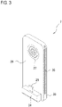
- an information-processing device 1 of the present embodiment includes: a smartphone 3 as a mobile terminal; a RFID reader unit (hereinafter called a "RFID unit” with reference numeral 5) as a reading unit; and a connection unit 7.
- the smartphone 3 has a liquid crystal display 9 and a touch panel 15.
- the smartphone 3 has a female connector 13 ( Fig. 4 ) on the periphery for connection with an external device.
- a principal surface of the smartphone 3 having the liquid crystal display 9 is called a front face
- the principal surface of the smartphone 3 on the other side is called a rear face 11.
- a face having the connector 13 is called a lower face 17, the face opposed to the lower face is called an upper face 19, and the other faces are called lateral faces 21.
- the smartphone 3 internally includes a CPU, a memory, a network interface and an interface for connected devices, which are not illustrated.
- the memory stores a scan application.
- the CPU executes the scan application, the CPU requests reading of data from the RFID unit 5, and provides a variety of services based on the data obtained from the RFID unit 5.
- the interface for connected devices is connected to a data terminal of the connector 13.
- the connector 13 has a power terminal, and the power terminal is connected to the internal power supply of the smartphone 3.
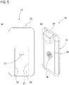
- connection unit 7 is a mobile unit that is disposed on the rear face 11 and is attached to the smartphone 3 for integral use with the smartphone 3.
- the connection unit includes a main body 23; a male connector 25 as a first terminal; and a pattern electrode 27 as a second terminal.
- the main body 23 has a rectangular plate part 29 to be disposed along the rear face 11 of the smartphone 3, and an elevated part 31 at the longitudinal one end of the plate part 29, the elevated part protruding in the thickness direction of the plate part 29.
- the plate part 29 has longitudinal lateral faces 33 on both sides, along each of which an engagement groove 35 is formed longitudinally. These engagement grooves 35 receive engagement projections 37 of the RFID unit 5 when the RFID unit is inserted by sliding. The thus engagement of the engagement grooves 35 with the engagement projections 37 allows the RFID unit 5 to be attached to the connection unit 7. When the RFID unit is slid in the opposite direction of the attachment, the engagement projections 37 are disengaged from the engagement grooves 35, whereby the RFID unit 5 can be removed from the connection unit 7.
- the male connector 25 protrudes from the elevated part 31 to be parallel to the principal faces of the plate part 29.
- the connector 25 has a power terminal and a data terminal, and these terminals are connected to the power terminal and the data terminal of the connector 13 ( Fig. 4 ) of the smartphone 3.
- the pattern electrode 27 includes a plurality of concentric electrodes each having a certain width, and is disposed on the rear face 51 (on the other side of the face opposed to the smartphone 3) of the plate part 29.
- the pattern electrode 27 includes an electrode for power and an electrode for data.
- Magconn registered trademark
- Magconn produced by Kotec Co., Ltd. may be typically used.
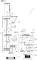
- the main body 23 internally includes a microcomputer having a CPU 39, a memory 41 and a communication port 43.
- This microcomputer is driven by power supplied from the smartphone 3 via the power terminal of the connector 25.
- the memory 41 stores a program.
- the CPU 39 executes this program, the CPU can manage exchange of data between the smartphone 3 and the RFID unit 5 via the communication port 43.
- the communication port 43 is electrically connected to the data terminal of the connector 25 and to the electrode for data of the pattern electrode 27.
- the power terminal of the connector 25 and the electrode for power of the pattern electrode 27 are electrically connected. In this way, the connector 25 and the pattern electrode 27 have an electrical pathway formed therebetween, and this electrical pathway connects the smartphone 3 and the RFID unit 5 electrically.
- the RFID unit 5 is a mobile reading unit that is attached to the connection unit 7 for integral use with the smartphone 3 and the connection unit 7.
- the RFID unit includes a main body 45; a projecting electrode 47 as a connecting terminal to be connected to the connection unit 7; and a pattern electrode 49 as a connecting terminal to be connected to another reading unit, for example.
- the main body 45 is disposed on the rear face 11 of the smartphone 3 and on the rear face 51 of the connection unit 7.
- the main body has a plate shape having a recess 53, into which the connection unit 7 is to be fitted.
- This recess 53 has lateral walls, on which the engagement projections 37 are formed for engagement with the engagement grooves 35 of the connection unit 7.
- the projecting electrode 47 includes an electrode for power and an electrode for data, and these electrodes project a little from the bottom face 55 of the recess 53. These electrodes are disposed so as to correspond to the electrodes of the pattern electrode 27 of the connection unit 7 in position.
- Magconn registered trademark
- the pattern electrode 49 includes a plurality of concentric electrodes each having a certain width, and is disposed on the rear face 57 of the main body 45.
- Magconn registered trademark
- Magconn may be used similarly to the pattern electrode 27 of the connection unit 7 as stated above.
- the RFID unit 5 internally includes a microcomputer having a CPU 59, a memory 61, and a communication port for RFID 63, a transmission unit for RFID 65, a reception unit for RFID 67 and an antenna 69.
- the memory 61 stores a program. When the CPU 59 executes the program, the CPU executes data reading processing described later, and transmits the read data.
- connection unit 7 When the connector 25 of the connection unit 7 is inserted into the connector 13 of the smartphone 3 as stated above, and then the RFID unit 5 is attached to the connection unit 7, the pattern electrode 27 of the connection unit 7 and the projecting electrode 47 of the RFID unit 5 are connected.
- the smartphone 3, the connection unit 7, and the RFID unit 5 can be used integrally and can function as the information-processing device 1. The following describes the operation of this information-processing device 1.
- the CPU of the smartphone 3 loads the scan application from the memory for execution. Then, when a user performs a predetermined operation using a GUI to start scanning, for example, the CPU of the smartphone 3 sends a request for data to the RFID unit 5 via the interface for connected devices and the connector 13.
- the CPU 39 of the connection unit 7 receives this request via the connector 25 and the communication port 43. Then the CPU 39 transfers the request to the RFID unit 5 via the communication port 43 and the pattern electrode 27.
- the CPU 59 of the RFID unit 5 receives this request via the projecting electrode 47 and the communication port for RFID 63. Then the CPU 59 executes the data reading processing. During the reading processing, the CPU 59 controls the transmission unit for RFID 65 to transmit radio waves, for example, from the antenna 69 so as to supply power to a RF tag 71. When the antenna 69 receives reflected waves from the RF tag 71, the CPU 59 controls the reception unit for RFID 67 to acquire data included in the reflected waves. Then the CPU 59 transmits the acquired data to the connection unit 7 via the communication port for RFID 63 and the projecting electrode 47.
- the CPU 39 of the connection unit 7 acquires the data via the pattern electrode 27 and the communication port 43, and transfers the data to the smartphone 3 via the communication port 43 and the connector 25.
- the CPU of the smartphone 3 When receiving the data from the connection unit 7 via the connector 13 and the interface for connected device, the CPU of the smartphone 3 provides a service based on the data.
- the information-processing device 1 may include a barcode reader unit (hereinafter called a "BC unit” with reference number 73) shown in Fig. 5 for operation, instead of the RFID unit 5.
- a barcode reader unit hereinafter called a "BC unit” with reference number 73
- the BC unit 73 is a mobile reading unit that is attached to the connection unit 7 for integral use with the smartphone 3 and the connection unit 7.
- the BC unit includes a main body 75; a projecting electrode 77 as a connecting terminal to be connected to the connection unit 7; and a pattern electrode 79 as a connecting terminal to be connected to another reading unit.
- the main body 75 includes a plate part 81 and a bay-window part 83.
- the plate part 81 is disposed on the rear face 11 of the smartphone 3 and on the rear face 51 of the connection unit 7.
- the plate part 81 is rectangular, and has a recess 85 from its longitudinal one end to a center part. Similarly to the RFID unit 5, this recess 85 is to fit the connection unit 7 and has engagement projections 37 for engagement with the engagement grooves 35 of the connection unit 7.
- the bay-window part 83 is a window to output light for scanning over a barcode 88 ( Fig. 4 ) and receive the reflected light.
- the bay-window part is disposed on the plate part 81 at a part corresponding to the upper face 19 of the smartphone 3. For the projecting electrode 77 and the pattern electrode 79, those similar to the RFID unit 5 may be used.
- the main body 75 internally includes a microcomputer having a CPU 87, a memory 89, and a communication port for barcode 99, a light source 91, a light-receiving element 93, an amplifier 95, and an A/D converter 97.
- the memory 89 stores a program beforehand. When the CPU 87 executes this program, the CPU executes data reading processing.
- the data reading processing starts with the reception by the CPU 87 of a request transferred from the connection unit 7.
- the CPU 87 controls the light source 91 to emit light. This leads to irradiation of the barcode 88 with the light from the bay-window part 83.
- the light-receiving element 93 receives the reflected light from the bay-window part 83, the light-receiving element 93 outputs an analog signal.
- This analog signal is input to the A/D converter 97 controlled by the CPU 87, and the A/D converter converts the analog signal to a digital signal.
- the CPU 87 acquires data assigned to the barcode based on this digital signal.
- the CPU 87 transmits the data to the connection unit 7 via the communication port for barcode 99 and the projecting electrode 77.
- connection unit 7 of the present embodiment the connector 25 comes in contact with the connector 13 of the smartphone 3, and the pattern electrode 27 comes in contact with the terminal 47, 77 of the reading unit, such as the RFID unit 5 or the BC unit 73 for electrical connection between the smartphone 3 and the reading unit. Therefore, the connection unit can reduce influences from noise and can avoid reliably a problem of a failure in transmission of data read by the reading unit.
- connection unit 7 is attached to the smartphone 3, to/from which the reading unit is attached/detached.
- the reading units can be replaced simply by detaching the reading unit from the connection unit 7. This can eliminate the attachment and detachment operation at the terminal of the smartphone 3 during the replacement of the reading units, and so can minimize the damage of the smartphone 3 resulting from such an operation.
- the information-processing device 1 of the present embodiment even when the connection unit 7 is damaged because of repeated attachment and detachment operations of the reading units, the connection unit 7 only may be renewed. Therefore cost can be saved as compared with the case where the smartphone 3 is damaged. As a result, as compared with a conventional system, the information-processing device of the present embodiment can reduce psychological burden on users during replacement of the reading units.
- the present embodiment is not limited to the above-stated modes.
- the following describes modified examples of the present embodiment.
- the mobile terminal is not limited to the smartphone 3, which may be a tablet PC.
- the configuration of the RFID unit 5 is not limited to the above.
- the RFID unit 5 may not have the transmission unit for RFID 65.
- the RFID unit may include a battery in the main body 45, and may be driven by power supplied from the battery.
- a switch (not illustrated) to switch between ON/OFF of the power supply of the RFID unit 5 may be provided separately.
- the configuration of the BC unit 73 also is not limited to the above.
- the BC unit may be configured to read a barcode by means of a CCD (Charge-Coupled Device) image sensor, or may be configured to apply laser to a barcode and receive reflected light with a light-receiving element.
- the BC unit may include a battery in the main body 75, and may be driven by power supplied from the battery.
- a switch (not illustrated) to switch between ON/OFF of the power supply of the BC unit 73 may be provided separately.
- the RFID unit 5 and the BC unit 73 may include a switch (not illustrated) to input a signal to the CPUs 59 and 87, respectively, to instruct reading of data.
- the CPU 59, 87 receives an input from the switch, the CPU executes the reading processing and transmits the read data to the connection unit 7.
- the CPU 39 of the connection unit 7 stores the received data in the memory 41 until the CPU receives a request from the mobile terminal.
- the CPU of the connection unit 7 reads the data from the memory and transmits the data to the mobile terminal.
- Such an information-processing device including the RFID unit 5 or the BC unit 73 and the connection unit 7 can continue the reading processing in response to inputting with the switch even when the scan application is interrupted because of a phone call coming during the reading processing, for example, and can store the read data in the memory of the connection unit 7. After the interruption of the scan application ends, the mobile terminal can acquire the stored data at one time. In this way, the information-processing device can improve the user friendliness.
- reading units such as a card reader unit to read data stored in an IC card and a biometric authentication unit for biometric authentication, may be used in addition to the RFID unit 5 and the BC unit 73. In this way, the reading units can be changed as needed in accordance with information media to be read.
- the mechanism to attach or detach the reading unit and the connection unit 7 is not limited to the above-stated mode using the engagement projections 37 and the engagement grooves 35.
- magnets may be disposed at the joining parts of both units so as to attach the reading unit to the connection unit 7 by a magnetic force of the magnets.
- the connecting terminals for the reading unit and the connection unit 7 are not limited to the above-stated mode through a contact between the projecting electrodes 47, 77 and the pattern electrode 27.
- Another connector may be used, for example, so as to correspond to the mechanism to attach or detach the reading unit and the connection unit 7.
- Embodiment 2 of the present invention The following describes Embodiment 2 of the present invention. Like reference numerals designate like parts of Embodiment 1, and their description is omitted.
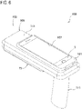
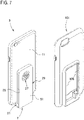
- an information-processing device 100 of the present embodiment includes: a smartphone 3 and a connection unit 7 that are integrated with a protective cover 101; a RFID unit 103, and a BC unit 73.
- the protective cover 101 is made of an elastic material, such as silicon. In the present embodiment, the protective cover is attached to the smartphone 3 and the connection unit 7 that are mutually connected.
- the protective cover 101 covers the peripheral faces and the rear face 11 of the smartphone 3.
- the protective cover 101 covers the elevated part 31 and the peripheral faces of the plate part 29 of the connection unit 7.
- the protective cover 101 has a hole 105 to expose the rear face 51 as a whole of the plate part 29 of the connection unit 7 and a hole 107 to expose the liquid crystal display 9.
- the RFID unit 103 has a shape like a gun, and includes a plate part 109 on which the smartphone 3 and the connection unit 7 that are integrated with the protective cover 101 is placed, and a grip 111 extending from the plate part 109 substantially perpendicularly.
- the mounting face 113 of the plate part 109 has a projecting electrode 115 as a connecting terminal.
- this projecting electrode 115 connects to the pattern electrode 27 ( Fig. 7 ) of the connection unit.
- the projecting electrode 115 and the pattern electrode 27 internally include magnets.
- the lower face 117 (on the other side of the mounting face 113) of the plate part 109 has a plate-like projection 119, to which the recess 85 of the BC unit 73 is to be fitted.
- the projection 119 has lateral faces 121, on each of which an engagement groove 123 is formed. Into these engagement grooves, the engagement projections 37 ( Fig. 5 ) of the BC unit 73 are inserted by sliding.
- the projection 119 has a principal face 125, and the principal face includes a pattern electrode 127 for connection with the projecting electrode 77 ( Fig. 5 ) of the BC unit 73.
- the integrated smartphone 3 and connection unit 7 is placed on such a RFID unit 103, to which the BC unit 73 is fitted, whereby the information-processing device 100 can be configured.
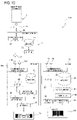
- the following describes the operation of this information-processing device 100, with reference to Fig. 10 .
- the CPU of the smartphone 3 sends a request for data to the RFID unit 103 or the BC unit 73.
- the CPU 39 of the connection unit 7 receives this request via the connector 25 and the communication port 43. Then the CPU 39 transfers the request to the RFID unit 103 via the communication port 43 and the pattern electrode 27.
- the CPU 59 of the RFID unit 103 receives the request via the projecting electrode 115 and the communication port for RFID 63.
- the CPU 59 executes data reading processing and transmits the acquired data to the connection unit 7 via the communication port for RFID 63 and the projecting electrode 115.
- the CPU 59 transfers the request to the BC unit 73 via the communication port for RFID 63 and the pattern electrode 127.
- the CPU 87 of the BC unit 73 receives the request via the projecting electrode 77 and the communication port for barcode 99.
- the CPU 87 executes data reading processing, and transmits the acquired data to the RFID unit 103 via the communication port for barcode 99 and the projecting electrode 77.
- the CPU 59 of the RFID unit 103 receives the data via the pattern electrode 127 and the communication port for RFID 63. Then the CPU 59 transfers the data to the connection unit 7 via the communication port for RFID 63 and the projecting electrode 115.
- the CPU 39 of the connection unit 7 receives the data via the pattern electrode 27 and the communication port 43.
- the CPU 39 transfers the received data to the smartphone 3 via the communication port 43 and the connector 25. In this way, the CPU of the smartphone 3 provides a service based on the data.
- a user can handle a plurality of reading units (the RFID unit 103 and the BC unit 73) integrally, and so the information-processing device is convenient for the user because the user does not need to replace the reading units depending on the types of information media.
- the RFID unit 103 includes the grip 111, the user can easily handle the information-processing device when reading data from many information media. In this way, a very user-friendly information-processing device 100 can be provided.
- the protective cover 101 can avoid damage of the smartphone 3.
- the material of the protective cover 101 is not limited to the above, and a hard material, such as plastic, may be used, for example.
- the protective cover may have a hole as needed for an earphone terminal of the smartphone 3, for example.
Landscapes
- Engineering & Computer Science (AREA)
- Physics & Mathematics (AREA)
- Toxicology (AREA)
- Health & Medical Sciences (AREA)
- Electromagnetism (AREA)
- Theoretical Computer Science (AREA)
- General Physics & Mathematics (AREA)
- Artificial Intelligence (AREA)
- Computer Vision & Pattern Recognition (AREA)
- General Health & Medical Sciences (AREA)
- Signal Processing (AREA)
- Computer Networks & Wireless Communication (AREA)
- Human Computer Interaction (AREA)
- General Engineering & Computer Science (AREA)
- Telephone Set Structure (AREA)
- Telephone Function (AREA)
Applications Claiming Priority (2)
| Application Number | Priority Date | Filing Date | Title |
|---|---|---|---|
| JP2016059196A JP7010579B2 (ja) | 2016-03-23 | 2016-03-23 | 接続ユニット、情報処理装置 |
| PCT/JP2017/010564 WO2017164049A1 (ja) | 2016-03-23 | 2017-03-16 | 接続ユニット、情報処理装置 |
Publications (3)
| Publication Number | Publication Date |
|---|---|
| EP3435638A1 EP3435638A1 (en) | 2019-01-30 |
| EP3435638A4 EP3435638A4 (en) | 2019-11-13 |
| EP3435638B1 true EP3435638B1 (en) | 2022-10-26 |
Family
ID=59900368
Family Applications (1)
| Application Number | Title | Priority Date | Filing Date |
|---|---|---|---|
| EP17770092.9A Active EP3435638B1 (en) | 2016-03-23 | 2017-03-16 | Connection unit and information processing device |
Country Status (6)
Families Citing this family (8)
| Publication number | Priority date | Publication date | Assignee | Title |
|---|---|---|---|---|
| GB2513039A (en) | 2012-01-17 | 2014-10-15 | Honeywell Int Inc | Industrial design for consumer device based on scanning and mobility |
| JP7010579B2 (ja) * | 2016-03-23 | 2022-01-26 | 株式会社アスタリスク | 接続ユニット、情報処理装置 |
| JP6897198B2 (ja) * | 2017-03-22 | 2021-06-30 | 株式会社デンソーウェーブ | 携帯型リーダに着脱可能な拡張操作装置 |
| JP6978954B2 (ja) * | 2018-01-29 | 2021-12-08 | 東日本旅客鉄道株式会社 | リーダライタ、携帯型決済端末機及び決済システム |
| DE102019125172A1 (de) * | 2019-09-18 | 2021-03-18 | Telefonaktiebolaget Lm Ericsson (Publ) | Antenne mit einer Strahlschwenkeinrichtung |
| JP7580313B2 (ja) * | 2021-03-18 | 2024-11-11 | 株式会社キーエンス | 情報読取セット、情報読取装置及び拡張モジュール |
| US20230237288A1 (en) * | 2022-01-21 | 2023-07-27 | Marson Technology Co., Ltd. | Rfid reader for smart phone by magnetic connection |
| US20230238738A1 (en) * | 2022-01-21 | 2023-07-27 | Marson Technology Co., Ltd. | Barcode scanner for smart phone by magnetic connection |
Family Cites Families (12)
| Publication number | Priority date | Publication date | Assignee | Title |
|---|---|---|---|---|
| JPH11252268A (ja) | 1998-03-03 | 1999-09-17 | Harness Syst Tech Res Ltd | 電話機接続用コネクタ |
| JP3896228B2 (ja) * | 1999-08-17 | 2007-03-22 | 松下電器産業株式会社 | バーコードリーダ取り付け具および携帯情報端末 |
| WO2006115371A1 (en) * | 2005-04-25 | 2006-11-02 | Lg Electronics Inc. | Reader control system |
| EP2018030A1 (en) * | 2007-07-18 | 2009-01-21 | Blue Bee Limited | A docking station and a kit for a personal electronic device |
| US9300081B2 (en) * | 2010-02-02 | 2016-03-29 | Charles Albert Rudisill | Interposer connectors with magnetic components |
| KR200467719Y1 (ko) * | 2012-08-31 | 2013-07-01 | (주)에스피에스 | 모바일 단말기의 백커버 |
| GB2514746B (en) | 2012-11-07 | 2016-01-27 | Koamtac Inc | Connectivity sled for electronic pairing and physical cooperation between a mobile device and associated peripheral devices |
| US9300083B2 (en) * | 2013-09-30 | 2016-03-29 | Apple Inc. | Stackable magnetically-retained connector interface |
| US9195279B2 (en) * | 2014-02-24 | 2015-11-24 | National Products, Inc. | Docking sleeve with electrical adapter |
| KR102232725B1 (ko) * | 2014-08-04 | 2021-03-26 | 삼성전자주식회사 | Nfc 장치의 동작 방법 및 nfc 장치 |
| US9767949B2 (en) * | 2015-06-15 | 2017-09-19 | Sony Corporation | Controlling of a magnetic connection between an electrical device and a cable |
| JP7010579B2 (ja) * | 2016-03-23 | 2022-01-26 | 株式会社アスタリスク | 接続ユニット、情報処理装置 |
-
2016
- 2016-03-23 JP JP2016059196A patent/JP7010579B2/ja active Active
-
2017
- 2017-03-16 WO PCT/JP2017/010564 patent/WO2017164049A1/ja active Application Filing
- 2017-03-16 US US15/575,034 patent/US10157299B2/en active Active
- 2017-03-16 EP EP17770092.9A patent/EP3435638B1/en active Active
- 2017-03-16 KR KR1020187021351A patent/KR102043430B1/ko not_active Expired - Fee Related
- 2017-03-17 CN CN201710161414.6A patent/CN107239808B/zh active Active
- 2017-03-17 CN CN201720263025.XU patent/CN206584385U/zh active Active
Also Published As
| Publication number | Publication date |
|---|---|
| CN107239808A (zh) | 2017-10-10 |
| US20180150665A1 (en) | 2018-05-31 |
| CN206584385U (zh) | 2017-10-24 |
| JP2017175386A (ja) | 2017-09-28 |
| EP3435638A1 (en) | 2019-01-30 |
| WO2017164049A1 (ja) | 2017-09-28 |
| EP3435638A4 (en) | 2019-11-13 |
| US10157299B2 (en) | 2018-12-18 |
| JP7010579B2 (ja) | 2022-01-26 |
| CN107239808B (zh) | 2022-08-02 |
| KR20180095695A (ko) | 2018-08-27 |
| KR102043430B1 (ko) | 2019-11-11 |
Similar Documents
| Publication | Publication Date | Title |
|---|---|---|
| EP3435638B1 (en) | Connection unit and information processing device | |
| US7764488B2 (en) | Wearable component with a memory arrangement | |
| JP3391375B2 (ja) | Icカードを備えた携帯電話機用バッテリ | |
| KR101383407B1 (ko) | 모바일 장치와 관련 주변 장치 간의 전자 페어링 및 물리적 협력을 위한 연결 슬레드 | |
| US9239590B2 (en) | Apparatus comprising a pistol grip | |
| US7966040B2 (en) | Magnetically attachable accessories for a mobile unit | |
| JP2012049846A (ja) | センサモジュール | |
| GB2514746A (en) | Connectivity sled for electronic pairing and physical cooperation between a mobile device and associated peripheral devices | |
| US6639790B2 (en) | Power supply module in a portable computer | |
| KR200483762Y1 (ko) | Rfid 및 바코드 겸용 단말 장치 | |
| US10659580B2 (en) | Connecting sled system for mobile devices | |
| CN110414281B (zh) | 信息读取装置 | |
| JP2017174382A (ja) | 接続ユニット、情報処理装置 | |
| JP3901018B2 (ja) | 光学情報読取装置 | |
| JP4257231B2 (ja) | 端末機用充電器 | |
| JP3966079B2 (ja) | 光学情報読取装置 | |
| JP7580313B2 (ja) | 情報読取セット、情報読取装置及び拡張モジュール | |
| JP2012118585A (ja) | 通信装置 | |
| JP2004213162A (ja) | 携帯電話機及びパーソナルコンピュータ用非接触通信simリーダライタ等と携帯電話機用simリーダライタ | |
| KR102557113B1 (ko) | 커넥터 및 접속 어댑터 | |
| JP2009145949A (ja) | Simホルダー | |
| JP4019862B2 (ja) | 光学情報読取装置 | |
| JP2016144280A (ja) | 携帯端末システム及び携帯端末 | |
| JP4894596B2 (ja) | 携帯型情報読取装置 | |
| CN204347859U (zh) | 能与移动电子产品结合的条码扫描装置 |
Legal Events
| Date | Code | Title | Description |
|---|---|---|---|
| STAA | Information on the status of an ep patent application or granted ep patent |
Free format text: STATUS: THE INTERNATIONAL PUBLICATION HAS BEEN MADE |
|
| PUAI | Public reference made under article 153(3) epc to a published international application that has entered the european phase |
Free format text: ORIGINAL CODE: 0009012 |
|
| STAA | Information on the status of an ep patent application or granted ep patent |
Free format text: STATUS: REQUEST FOR EXAMINATION WAS MADE |
|
| 17P | Request for examination filed |
Effective date: 20180515 |
|
| AK | Designated contracting states |
Kind code of ref document: A1 Designated state(s): AL AT BE BG CH CY CZ DE DK EE ES FI FR GB GR HR HU IE IS IT LI LT LU LV MC MK MT NL NO PL PT RO RS SE SI SK SM TR |
|
| AX | Request for extension of the european patent |
Extension state: BA ME |
|
| DAV | Request for validation of the european patent (deleted) | ||
| DAX | Request for extension of the european patent (deleted) | ||
| A4 | Supplementary search report drawn up and despatched |
Effective date: 20191016 |
|
| RIC1 | Information provided on ipc code assigned before grant |
Ipc: H04M 1/21 20060101AFI20191010BHEP Ipc: G06K 7/10 20060101ALI20191010BHEP |
|
| STAA | Information on the status of an ep patent application or granted ep patent |
Free format text: STATUS: EXAMINATION IS IN PROGRESS |
|
| 17Q | First examination report despatched |
Effective date: 20210205 |
|
| STAA | Information on the status of an ep patent application or granted ep patent |
Free format text: STATUS: EXAMINATION IS IN PROGRESS |
|
| GRAP | Despatch of communication of intention to grant a patent |
Free format text: ORIGINAL CODE: EPIDOSNIGR1 |
|
| STAA | Information on the status of an ep patent application or granted ep patent |
Free format text: STATUS: GRANT OF PATENT IS INTENDED |
|
| INTG | Intention to grant announced |
Effective date: 20220506 |
|
| GRAS | Grant fee paid |
Free format text: ORIGINAL CODE: EPIDOSNIGR3 |
|
| GRAA | (expected) grant |
Free format text: ORIGINAL CODE: 0009210 |
|
| STAA | Information on the status of an ep patent application or granted ep patent |
Free format text: STATUS: THE PATENT HAS BEEN GRANTED |
|
| AK | Designated contracting states |
Kind code of ref document: B1 Designated state(s): AL AT BE BG CH CY CZ DE DK EE ES FI FR GB GR HR HU IE IS IT LI LT LU LV MC MK MT NL NO PL PT RO RS SE SI SK SM TR |
|
| REG | Reference to a national code |
Ref country code: GB Ref legal event code: FG4D |
|
| REG | Reference to a national code |
Ref country code: CH Ref legal event code: EP |
|
| REG | Reference to a national code |
Ref country code: DE Ref legal event code: R096 Ref document number: 602017063050 Country of ref document: DE |
|
| REG | Reference to a national code |
Ref country code: AT Ref legal event code: REF Ref document number: 1527922 Country of ref document: AT Kind code of ref document: T Effective date: 20221115 |
|
| REG | Reference to a national code |
Ref country code: IE Ref legal event code: FG4D |
|
| REG | Reference to a national code |
Ref country code: LT Ref legal event code: MG9D |
|
| REG | Reference to a national code |
Ref country code: NL Ref legal event code: MP Effective date: 20221026 |
|
| REG | Reference to a national code |
Ref country code: AT Ref legal event code: MK05 Ref document number: 1527922 Country of ref document: AT Kind code of ref document: T Effective date: 20221026 |
|
| PG25 | Lapsed in a contracting state [announced via postgrant information from national office to epo] |
Ref country code: NL Free format text: LAPSE BECAUSE OF FAILURE TO SUBMIT A TRANSLATION OF THE DESCRIPTION OR TO PAY THE FEE WITHIN THE PRESCRIBED TIME-LIMIT Effective date: 20221026 |
|
| PG25 | Lapsed in a contracting state [announced via postgrant information from national office to epo] |
Ref country code: SE Free format text: LAPSE BECAUSE OF FAILURE TO SUBMIT A TRANSLATION OF THE DESCRIPTION OR TO PAY THE FEE WITHIN THE PRESCRIBED TIME-LIMIT Effective date: 20221026 Ref country code: PT Free format text: LAPSE BECAUSE OF FAILURE TO SUBMIT A TRANSLATION OF THE DESCRIPTION OR TO PAY THE FEE WITHIN THE PRESCRIBED TIME-LIMIT Effective date: 20230227 Ref country code: NO Free format text: LAPSE BECAUSE OF FAILURE TO SUBMIT A TRANSLATION OF THE DESCRIPTION OR TO PAY THE FEE WITHIN THE PRESCRIBED TIME-LIMIT Effective date: 20230126 Ref country code: LT Free format text: LAPSE BECAUSE OF FAILURE TO SUBMIT A TRANSLATION OF THE DESCRIPTION OR TO PAY THE FEE WITHIN THE PRESCRIBED TIME-LIMIT Effective date: 20221026 Ref country code: FI Free format text: LAPSE BECAUSE OF FAILURE TO SUBMIT A TRANSLATION OF THE DESCRIPTION OR TO PAY THE FEE WITHIN THE PRESCRIBED TIME-LIMIT Effective date: 20221026 Ref country code: ES Free format text: LAPSE BECAUSE OF FAILURE TO SUBMIT A TRANSLATION OF THE DESCRIPTION OR TO PAY THE FEE WITHIN THE PRESCRIBED TIME-LIMIT Effective date: 20221026 Ref country code: AT Free format text: LAPSE BECAUSE OF FAILURE TO SUBMIT A TRANSLATION OF THE DESCRIPTION OR TO PAY THE FEE WITHIN THE PRESCRIBED TIME-LIMIT Effective date: 20221026 |
|
| PG25 | Lapsed in a contracting state [announced via postgrant information from national office to epo] |
Ref country code: RS Free format text: LAPSE BECAUSE OF FAILURE TO SUBMIT A TRANSLATION OF THE DESCRIPTION OR TO PAY THE FEE WITHIN THE PRESCRIBED TIME-LIMIT Effective date: 20221026 Ref country code: PL Free format text: LAPSE BECAUSE OF FAILURE TO SUBMIT A TRANSLATION OF THE DESCRIPTION OR TO PAY THE FEE WITHIN THE PRESCRIBED TIME-LIMIT Effective date: 20221026 Ref country code: LV Free format text: LAPSE BECAUSE OF FAILURE TO SUBMIT A TRANSLATION OF THE DESCRIPTION OR TO PAY THE FEE WITHIN THE PRESCRIBED TIME-LIMIT Effective date: 20221026 Ref country code: IS Free format text: LAPSE BECAUSE OF FAILURE TO SUBMIT A TRANSLATION OF THE DESCRIPTION OR TO PAY THE FEE WITHIN THE PRESCRIBED TIME-LIMIT Effective date: 20230226 Ref country code: HR Free format text: LAPSE BECAUSE OF FAILURE TO SUBMIT A TRANSLATION OF THE DESCRIPTION OR TO PAY THE FEE WITHIN THE PRESCRIBED TIME-LIMIT Effective date: 20221026 Ref country code: GR Free format text: LAPSE BECAUSE OF FAILURE TO SUBMIT A TRANSLATION OF THE DESCRIPTION OR TO PAY THE FEE WITHIN THE PRESCRIBED TIME-LIMIT Effective date: 20230127 |
|
| REG | Reference to a national code |
Ref country code: DE Ref legal event code: R097 Ref document number: 602017063050 Country of ref document: DE |
|
| PG25 | Lapsed in a contracting state [announced via postgrant information from national office to epo] |
Ref country code: SM Free format text: LAPSE BECAUSE OF FAILURE TO SUBMIT A TRANSLATION OF THE DESCRIPTION OR TO PAY THE FEE WITHIN THE PRESCRIBED TIME-LIMIT Effective date: 20221026 Ref country code: RO Free format text: LAPSE BECAUSE OF FAILURE TO SUBMIT A TRANSLATION OF THE DESCRIPTION OR TO PAY THE FEE WITHIN THE PRESCRIBED TIME-LIMIT Effective date: 20221026 Ref country code: EE Free format text: LAPSE BECAUSE OF FAILURE TO SUBMIT A TRANSLATION OF THE DESCRIPTION OR TO PAY THE FEE WITHIN THE PRESCRIBED TIME-LIMIT Effective date: 20221026 Ref country code: DK Free format text: LAPSE BECAUSE OF FAILURE TO SUBMIT A TRANSLATION OF THE DESCRIPTION OR TO PAY THE FEE WITHIN THE PRESCRIBED TIME-LIMIT Effective date: 20221026 Ref country code: CZ Free format text: LAPSE BECAUSE OF FAILURE TO SUBMIT A TRANSLATION OF THE DESCRIPTION OR TO PAY THE FEE WITHIN THE PRESCRIBED TIME-LIMIT Effective date: 20221026 |
|
| PG25 | Lapsed in a contracting state [announced via postgrant information from national office to epo] |
Ref country code: SK Free format text: LAPSE BECAUSE OF FAILURE TO SUBMIT A TRANSLATION OF THE DESCRIPTION OR TO PAY THE FEE WITHIN THE PRESCRIBED TIME-LIMIT Effective date: 20221026 Ref country code: AL Free format text: LAPSE BECAUSE OF FAILURE TO SUBMIT A TRANSLATION OF THE DESCRIPTION OR TO PAY THE FEE WITHIN THE PRESCRIBED TIME-LIMIT Effective date: 20221026 |
|
| PLBE | No opposition filed within time limit |
Free format text: ORIGINAL CODE: 0009261 |
|
| STAA | Information on the status of an ep patent application or granted ep patent |
Free format text: STATUS: NO OPPOSITION FILED WITHIN TIME LIMIT |
|
| 26N | No opposition filed |
Effective date: 20230727 |
|
| PG25 | Lapsed in a contracting state [announced via postgrant information from national office to epo] |
Ref country code: MC Free format text: LAPSE BECAUSE OF FAILURE TO SUBMIT A TRANSLATION OF THE DESCRIPTION OR TO PAY THE FEE WITHIN THE PRESCRIBED TIME-LIMIT Effective date: 20221026 |
|
| REG | Reference to a national code |
Ref country code: CH Ref legal event code: PL |
|
| PG25 | Lapsed in a contracting state [announced via postgrant information from national office to epo] |
Ref country code: SI Free format text: LAPSE BECAUSE OF FAILURE TO SUBMIT A TRANSLATION OF THE DESCRIPTION OR TO PAY THE FEE WITHIN THE PRESCRIBED TIME-LIMIT Effective date: 20221026 |
|
| REG | Reference to a national code |
Ref country code: BE Ref legal event code: MM Effective date: 20230331 |
|
| PG25 | Lapsed in a contracting state [announced via postgrant information from national office to epo] |
Ref country code: LU Free format text: LAPSE BECAUSE OF NON-PAYMENT OF DUE FEES Effective date: 20230316 |
|
| REG | Reference to a national code |
Ref country code: IE Ref legal event code: MM4A |
|
| PG25 | Lapsed in a contracting state [announced via postgrant information from national office to epo] |
Ref country code: LI Free format text: LAPSE BECAUSE OF NON-PAYMENT OF DUE FEES Effective date: 20230331 Ref country code: IE Free format text: LAPSE BECAUSE OF NON-PAYMENT OF DUE FEES Effective date: 20230316 Ref country code: CH Free format text: LAPSE BECAUSE OF NON-PAYMENT OF DUE FEES Effective date: 20230331 |
|
| PG25 | Lapsed in a contracting state [announced via postgrant information from national office to epo] |
Ref country code: BE Free format text: LAPSE BECAUSE OF NON-PAYMENT OF DUE FEES Effective date: 20230331 |
|
| PGFP | Annual fee paid to national office [announced via postgrant information from national office to epo] |
Ref country code: DE Payment date: 20240320 Year of fee payment: 8 Ref country code: GB Payment date: 20240322 Year of fee payment: 8 |
|
| PG25 | Lapsed in a contracting state [announced via postgrant information from national office to epo] |
Ref country code: IT Free format text: LAPSE BECAUSE OF FAILURE TO SUBMIT A TRANSLATION OF THE DESCRIPTION OR TO PAY THE FEE WITHIN THE PRESCRIBED TIME-LIMIT Effective date: 20221026 |
|
| PGFP | Annual fee paid to national office [announced via postgrant information from national office to epo] |
Ref country code: FR Payment date: 20240320 Year of fee payment: 8 |
|
| PG25 | Lapsed in a contracting state [announced via postgrant information from national office to epo] |
Ref country code: BG Free format text: LAPSE BECAUSE OF FAILURE TO SUBMIT A TRANSLATION OF THE DESCRIPTION OR TO PAY THE FEE WITHIN THE PRESCRIBED TIME-LIMIT Effective date: 20221026 |
|
| PG25 | Lapsed in a contracting state [announced via postgrant information from national office to epo] |
Ref country code: BG Free format text: LAPSE BECAUSE OF FAILURE TO SUBMIT A TRANSLATION OF THE DESCRIPTION OR TO PAY THE FEE WITHIN THE PRESCRIBED TIME-LIMIT Effective date: 20221026 |
|
| PG25 | Lapsed in a contracting state [announced via postgrant information from national office to epo] |
Ref country code: CY Free format text: LAPSE BECAUSE OF FAILURE TO SUBMIT A TRANSLATION OF THE DESCRIPTION OR TO PAY THE FEE WITHIN THE PRESCRIBED TIME-LIMIT; INVALID AB INITIO Effective date: 20170316 |
|
| PG25 | Lapsed in a contracting state [announced via postgrant information from national office to epo] |
Ref country code: HU Free format text: LAPSE BECAUSE OF FAILURE TO SUBMIT A TRANSLATION OF THE DESCRIPTION OR TO PAY THE FEE WITHIN THE PRESCRIBED TIME-LIMIT; INVALID AB INITIO Effective date: 20170316 |