EP3434897B1 - Kompressorvorrichtung, eine damit ausgerüstete kühlvorrichtung und ein verfahren zum betreiben der kompressorvorrichtung und der kühlvorrichtung - Google Patents
Kompressorvorrichtung, eine damit ausgerüstete kühlvorrichtung und ein verfahren zum betreiben der kompressorvorrichtung und der kühlvorrichtung Download PDFInfo
- Publication number
- EP3434897B1 EP3434897B1 EP18195959.4A EP18195959A EP3434897B1 EP 3434897 B1 EP3434897 B1 EP 3434897B1 EP 18195959 A EP18195959 A EP 18195959A EP 3434897 B1 EP3434897 B1 EP 3434897B1
- Authority
- EP
- European Patent Office
- Prior art keywords
- gas
- pressure
- compressor
- working
- volume
- Prior art date
- Legal status (The legal status is an assumption and is not a legal conclusion. Google has not performed a legal analysis and makes no representation as to the accuracy of the status listed.)
- Active
Links
Images

Classifications
-
- F—MECHANICAL ENGINEERING; LIGHTING; HEATING; WEAPONS; BLASTING
- F04—POSITIVE - DISPLACEMENT MACHINES FOR LIQUIDS; PUMPS FOR LIQUIDS OR ELASTIC FLUIDS
- F04B—POSITIVE-DISPLACEMENT MACHINES FOR LIQUIDS; PUMPS
- F04B45/00—Pumps or pumping installations having flexible working members and specially adapted for elastic fluids
- F04B45/02—Pumps or pumping installations having flexible working members and specially adapted for elastic fluids having bellows
- F04B45/022—Pumps or pumping installations having flexible working members and specially adapted for elastic fluids having bellows with two or more bellows in parallel
-
- F—MECHANICAL ENGINEERING; LIGHTING; HEATING; WEAPONS; BLASTING
- F04—POSITIVE - DISPLACEMENT MACHINES FOR LIQUIDS; PUMPS FOR LIQUIDS OR ELASTIC FLUIDS
- F04B—POSITIVE-DISPLACEMENT MACHINES FOR LIQUIDS; PUMPS
- F04B37/00—Pumps having pertinent characteristics not provided for in, or of interest apart from, groups F04B25/00 - F04B35/00
- F04B37/10—Pumps having pertinent characteristics not provided for in, or of interest apart from, groups F04B25/00 - F04B35/00 for special use
- F04B37/12—Pumps having pertinent characteristics not provided for in, or of interest apart from, groups F04B25/00 - F04B35/00 for special use to obtain high pressure
-
- F—MECHANICAL ENGINEERING; LIGHTING; HEATING; WEAPONS; BLASTING
- F04—POSITIVE - DISPLACEMENT MACHINES FOR LIQUIDS; PUMPS FOR LIQUIDS OR ELASTIC FLUIDS
- F04B—POSITIVE-DISPLACEMENT MACHINES FOR LIQUIDS; PUMPS
- F04B37/00—Pumps having pertinent characteristics not provided for in, or of interest apart from, groups F04B25/00 - F04B35/00
- F04B37/10—Pumps having pertinent characteristics not provided for in, or of interest apart from, groups F04B25/00 - F04B35/00 for special use
- F04B37/18—Pumps having pertinent characteristics not provided for in, or of interest apart from, groups F04B25/00 - F04B35/00 for special use for specific elastic fluids
-
- F—MECHANICAL ENGINEERING; LIGHTING; HEATING; WEAPONS; BLASTING
- F04—POSITIVE - DISPLACEMENT MACHINES FOR LIQUIDS; PUMPS FOR LIQUIDS OR ELASTIC FLUIDS
- F04B—POSITIVE-DISPLACEMENT MACHINES FOR LIQUIDS; PUMPS
- F04B45/00—Pumps or pumping installations having flexible working members and specially adapted for elastic fluids
- F04B45/02—Pumps or pumping installations having flexible working members and specially adapted for elastic fluids having bellows
- F04B45/024—Pumps or pumping installations having flexible working members and specially adapted for elastic fluids having bellows with two or more bellows in series
-
- F—MECHANICAL ENGINEERING; LIGHTING; HEATING; WEAPONS; BLASTING
- F04—POSITIVE - DISPLACEMENT MACHINES FOR LIQUIDS; PUMPS FOR LIQUIDS OR ELASTIC FLUIDS
- F04B—POSITIVE-DISPLACEMENT MACHINES FOR LIQUIDS; PUMPS
- F04B45/00—Pumps or pumping installations having flexible working members and specially adapted for elastic fluids
- F04B45/02—Pumps or pumping installations having flexible working members and specially adapted for elastic fluids having bellows
- F04B45/033—Pumps or pumping installations having flexible working members and specially adapted for elastic fluids having bellows having fluid drive
-
- F—MECHANICAL ENGINEERING; LIGHTING; HEATING; WEAPONS; BLASTING
- F25—REFRIGERATION OR COOLING; COMBINED HEATING AND REFRIGERATION SYSTEMS; HEAT PUMP SYSTEMS; MANUFACTURE OR STORAGE OF ICE; LIQUEFACTION SOLIDIFICATION OF GASES
- F25B—REFRIGERATION MACHINES, PLANTS OR SYSTEMS; COMBINED HEATING AND REFRIGERATION SYSTEMS; HEAT PUMP SYSTEMS
- F25B9/00—Compression machines, plants or systems, in which the refrigerant is air or other gas of low boiling point
- F25B9/02—Compression machines, plants or systems, in which the refrigerant is air or other gas of low boiling point using Joule-Thompson effect; using vortex effect
Definitions
- the invention relates to a compressor device, a cooling device equipped therewith and a method for operating the compressor device.
- pulse tube coolers or Gifford-McMahon coolers are used for cooling magnetic resonance tomographs, cryopumps, etc.
- Gas and especially helium compressors are used in combination with rotary or rotary valves.
- the rate at which compressed helium is introduced and re-circulated to the cooling device is in the range of 1 Hz.
- a problem with conventional screw or piston compressors is that oil from the compressor enters the working gas and thus the cooling device can contaminate.
- acoustic compressors or high-frequency compressors in which one or more pistons are caused by a magnetic field in linear resonant vibrations. These resonant frequencies are in the range of a few 10 Hz and are therefore not suitable for use with pulse tube coolers and Gifford-McMahon coolers to produce very low temperatures in the lower than 10 K range.
- a membrane compressor or pump which has a working space which is subdivided into a gas volume and a liquid volume by an elastic, gas- and liquid-tight membrane.
- a liquid pump liquid is periodically pressed into the liquid volume of the working space, whereby the elastic membrane expands in the direction of gas volume and this compresses - compressor function - or pushing out of the gas volume - pump function.
- the disadvantage here is that the gas-, liquid-tight and pressure-resistant sealing of the elastic membrane in the working space is relatively expensive. Particularly in the area of sealing, the membrane is heavily loaded, so that either very expensive materials must be used or a shorter life has to be accepted.
- CH 457 147 A also shows a membrane compressor and mentions the lack of tightness of the membrane to helium.
- DE 20 2007 018538 U1 shows a multi-stage diaphragm suction pump whose pumping chambers work in parallel or serially.
- a heat pump and a refrigerator with a compressor device are known.
- the compressor device comprises a compressor chamber in which a balloon is arranged.
- the balloon is periodically pressurized with liquid so that the gas surrounding the balloon is periodically compressed and relaxed again.
- the disadvantage here is that the balloon envelope can scrape or rub in certain operating conditions on the hard and possibly edged inner surface of the compressor chamber. As a result, due to the pressure conditions hole or cracking in the balloon envelope occur.
- the permeability - permeability - of the balloon envelope for helium as a working gas is too large, so you quickly lose substantial amounts of helium. Thus, the service life of such systems with balloon is unsatisfactory.
- a diaphragm pump for liquids which can also serve as a "gas compression pump".
- a liquid must be introduced between the membrane and pump valves, ie a liquid is provided in the gas space. It is thus a compression device with a liquid stamp. A physical separation between compressed gas and hydraulic fluid therefore does not take place.
- DE 10 2008 060598 A1 shows an apparatus for compressing a gas, comprising two cylinder filled with a hydraulic fluid or a working gas. The hydraulic fluid is preferably pumped back and forth between these cylinders with a hydraulic pump. Again, the physical separation between gas and liquid is not sufficient.
- US 1 580 479 A describes a diaphragm pump with two chambers (or bellows) without working fluid, which are mutually compressed or relaxed via a yoke separating the chambers.
- a compressor device with a metal bellows is known as a compressor element, with the exception of hydrogen for all possible working gases is impermeable.
- the working gas can also be kept oil-free due to the metal bellows.
- the efficiency due to the interaction with the working fluid balance tank is unsatisfactory.
- the common pumping device is used twice. In each flow direction of the working fluid is a compression of the working gas; in the one flow direction in the first compressor stage and in the opposite flow direction in the second compressor stage. This increases the efficiency of the compressor device. Characterized in that the high and low pressure gas line are designed so that they act as a gas storage due to their volume, the operating frequency of a compressor operated with the device cooler can be decoupled from the pumping frequency of the pumping device.
- the compressor device according to the present invention may be configured as a non-conveying compressor device.
- a predetermined amount of working gas is alternately compressed and relaxed in the two stages. There is no working gas supplied from the outside.
- a low-pressure gas storage and a high-pressure gas storage may be explicitly provided in the low-pressure or high-pressure gas line.
- a working fluid preferably hydraulic oil according to DIN 51524 is used, which is additionally dehydrated or anhydrous.
- the hydraulic oil is in a closed system of pumping device, working fluid equalizing device and fluid volume in the compressor chamber, so that during operation no water from the environment can be absorbed by the hydraulic oil.
- water can also be used as the working fluid.
- Water as a working fluid is also advantageous because, in the event of defects in a downstream cryogenic cooler, water which has penetrated can be removed more easily than hydraulic oil which has penetrated into a downstream cooler.
- water is suitable as a working medium in explosion-protected applications, since water is non-flammable and non-explosive. In addition, water is non-toxic and therefore environmentally friendly.
- helium, neon or nitrogen is preferably used as working gas.
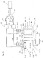
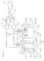
- Fig. 1 shows an embodiment of the compressor device according to the invention with a first and a second compressor stage 2-1, 2-2, in the form of a non-promotional compressor device.
- Each of the two compressor devices 2-1, 2-2 has a gas-tight closed compressor chamber 4-1, 4-2.
- a metal bellows 6-1, 6-2 is arranged in each of the two compressor rooms 4-1, 4-2.
- the metal bellows 6-1, 6-2 divide the compressor chambers 4-1, 4-2 into first and second gas volumes 8-1, 8-2 for a working gas 10 and into first and second fluid volumes 12-1, 12-2, respectively for a working liquid 14.
- the gas volumes 8-1, 8-2 are inside the metal bellows 6-1, 6-2, and the liquid volumes are outside the bellows 6-1, 6-2.
- the gas volumes 8-1, 8-2 are respectively connected to a high pressure working gas port 18-1, 18-2 and a low pressure working gas port 20-1, 20-2.
- the low pressure working gas ports 20-1, 20-2 are provided with check valves 22 which are permeable toward the compressor stages 2-1, 2-2.
- the high pressure working gas ports 18-1, 18-2 are also provided with check valves 22 which have opposite directions of passage as the check valves 22 at the low pressure working gas ports 20-1, 20-2.
- the high pressure working gas ports 18-1, 18-2 are connected via the check valves 22 to a common high pressure gas line 24, and the low pressure working gas ports 20-1, 20-2 are connected to a low pressure gas line 26 via the check valves 22.
- the check valves 22 in the high-pressure working gas ports 18-1, 18-2 are in the direction of common high-pressure gas line 24 and the check valves 22 on the low-pressure working gas ports 20-1, 20-2 are in the direction of compressor stages 2-1, 2-2 permeable.
- the common high pressure gas line 24 and the common low pressure gas line 26 terminate in a motorized rotary valve 28 which alternately the high pressure gas line 24 and the low pressure gas line 26 with a cooling device 30, for.
- the high and low pressure gas line 24, 26 act due to their volume as a gas storage or there are explicitly a low-pressure gas storage 27 and a high-pressure gas storage 25 in the low-pressure or high-pressure gas line 26, 24 are provided.
- the check valves 22 at the two high pressure working gas ports 18-1, 18-2 are each followed by heat exchangers 32-1, 32-2 for cooling the compressed working gas.
- the two compressor stages 2-1, 2-1 are constructed analogously, ie, the gas volumes 8-1, 8-2 and the liquid volumes 12-1, 12-2 are equal.
- the two working fluid ports 16-1, 16-2 are connected to a common electromotive pumping device 34 which alternately supplies working fluid 14 into the first and second fluid volumes 12-1, 12-2 of the first and second compressor stages 2-1, 2-2 pumps. Ie. either working fluid 14 is pumped from the second fluid volume 12-2 into the first fluid volume 12-1 or vice versa.
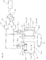
- FIGS. 2a to 2e illustrate the various phases of operation of the compressor device Fig. 1 ,
- the in Fig. 2a phase shown is pumped by the common pumping device 34 working fluid 14 from the second fluid volume 12-2 of the second compressor stage 2-2 in the first fluid volume 12-1 in the first compressor stage 2-1.
- the first metal bellows 6-1 is compressed and the working gas 10 therein is pressed into the high pressure gas reservoir 25 via the first high pressure working gas port 18-1, the first heat exchanger 32-1 and the common high pressure gas line 24.
- the second metal bellows 6-2 expands through working gas 10, which flows back out of the low-pressure working gas reservoir 27 via the low-pressure gas line 26 and the second low-pressure working gas connection 20-2.
- the rotary valve 28 connects the cooling device 30 via the low pressure gas line 26 with the low pressure gas storage 27th
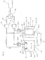
- the working fluid flow is reversed and the pumping device 34 now pumps working fluid 14 from the first fluid volume 12-1 of the first compressor stage 2-1 in the second fluid volume 12-2 in the second compressor stage 2-2.
- the second metal bellows 6-2 is compressed and the working gas 10 therein is compressed and pressed into the high pressure gas reservoir 25 via the second high pressure working gas port 18-1, the second heat exchanger 32-2 and the common high pressure gas line 24.
- the first metal bellows 6-1 expands through working gas 10 flowing back from the low-pressure gas reservoir 27 via the low-pressure gas line 26 and the first low-pressure working gas port 20-1.
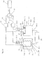
- Fig. 2e phase shown is again the first phase and the compression takes place in the first compressor stage 2-1.
- Fig. 2a and 2e differ only in that in Fig. 2e the first metal bellows 6-1 still relaxed and the second metal bellows 6-2 is still compressed.
- Fig. 2a is the compression in the first compressor stage 2-1 completed and the first metal bellows 6-1 is compressed, while the second metal bellows 6-2 is relaxed.
- the rotational frequency of the rotary valve 28 is decoupled from the frequency of the compression in the two compressor stages.
- the rotational frequency of the rotary valve 28 may be synchronized with the frequency of the compressor strokes.
- the high-pressure and low-pressure gas storage 25, 27 could be dispensed with.
- Hydraulic oils according to DIN 51524 are suitable as working fluids. These H, HL, HLP and HVLP oils are oils which are well tolerated with common sealants such as NBR (acrylonitrile butadiene rubber) etc. NBR, however, is not sufficiently helium-tight. HF oils are often incompatible with commonly used sealing materials ( http://de.wikipedia.org/wiki/List_of_Plastic_materials ).
- water can also be used as the working fluid.
- Water as a working fluid is also advantageous because in the event of defects, water that has penetrated into a downstream cryocooler can be removed more easily than hydraulic oil that has entered a downstream cooler.
- water is suitable as a working medium in explosion-protected applications, since water is non-flammable and non-explosive. In addition, water is non-toxic and therefore environmentally friendly.
Landscapes
- Engineering & Computer Science (AREA)
- Mechanical Engineering (AREA)
- General Engineering & Computer Science (AREA)
- Physics & Mathematics (AREA)
- Thermal Sciences (AREA)
- Compressors, Vaccum Pumps And Other Relevant Systems (AREA)
- Reciprocating Pumps (AREA)
Applications Claiming Priority (3)
| Application Number | Priority Date | Filing Date | Title |
|---|---|---|---|
| DE102014217897.5A DE102014217897A1 (de) | 2014-09-08 | 2014-09-08 | Kompressorvorrichtung, eine damit ausgerüstete Kühlvorrichtung und ein Verfahren zum Betreiben der Kompressorvorrichtung und der Kühlvorrichtung |
| PCT/EP2015/070507 WO2016038041A1 (de) | 2014-09-08 | 2015-09-08 | Kompressorvorrichtung, eine damit ausgerüstete kühlvorrichtung und ein verfahren zum betreiben der kompressorvorrichtung und der kühlvorrichtung |
| EP15774869.0A EP3191712B1 (de) | 2014-09-08 | 2015-09-08 | Kompressorvorrichtung, eine damit ausgerüstete kühlvorrichtung und ein verfahren zum betreiben der kompressorvorrichtung und der kühlvorrichtung |
Related Parent Applications (2)
| Application Number | Title | Priority Date | Filing Date |
|---|---|---|---|
| EP15774869.0A Division-Into EP3191712B1 (de) | 2014-09-08 | 2015-09-08 | Kompressorvorrichtung, eine damit ausgerüstete kühlvorrichtung und ein verfahren zum betreiben der kompressorvorrichtung und der kühlvorrichtung |
| EP15774869.0A Division EP3191712B1 (de) | 2014-09-08 | 2015-09-08 | Kompressorvorrichtung, eine damit ausgerüstete kühlvorrichtung und ein verfahren zum betreiben der kompressorvorrichtung und der kühlvorrichtung |
Publications (2)
| Publication Number | Publication Date |
|---|---|
| EP3434897A1 EP3434897A1 (de) | 2019-01-30 |
| EP3434897B1 true EP3434897B1 (de) | 2019-12-11 |
Family
ID=54251480
Family Applications (2)
| Application Number | Title | Priority Date | Filing Date |
|---|---|---|---|
| EP15774869.0A Active EP3191712B1 (de) | 2014-09-08 | 2015-09-08 | Kompressorvorrichtung, eine damit ausgerüstete kühlvorrichtung und ein verfahren zum betreiben der kompressorvorrichtung und der kühlvorrichtung |
| EP18195959.4A Active EP3434897B1 (de) | 2014-09-08 | 2015-09-08 | Kompressorvorrichtung, eine damit ausgerüstete kühlvorrichtung und ein verfahren zum betreiben der kompressorvorrichtung und der kühlvorrichtung |
Family Applications Before (1)
| Application Number | Title | Priority Date | Filing Date |
|---|---|---|---|
| EP15774869.0A Active EP3191712B1 (de) | 2014-09-08 | 2015-09-08 | Kompressorvorrichtung, eine damit ausgerüstete kühlvorrichtung und ein verfahren zum betreiben der kompressorvorrichtung und der kühlvorrichtung |
Country Status (6)
| Country | Link |
|---|---|
| US (1) | US11028841B2 (enExample) |
| EP (2) | EP3191712B1 (enExample) |
| JP (1) | JP6594959B2 (enExample) |
| CN (1) | CN107094367B (enExample) |
| DE (1) | DE102014217897A1 (enExample) |
| WO (1) | WO2016038041A1 (enExample) |
Families Citing this family (7)
| Publication number | Priority date | Publication date | Assignee | Title |
|---|---|---|---|---|
| JP6975077B2 (ja) * | 2018-03-07 | 2021-12-01 | 住友重機械工業株式会社 | 極低温冷凍機および極低温冷凍機の給電系統 |
| US20220010934A1 (en) * | 2020-07-10 | 2022-01-13 | University Of Maryland, College Park | System and method for efficient isothermal compression |
| DE102021002178A1 (de) * | 2021-04-24 | 2022-10-27 | Hydac Technology Gmbh | Fördereinrichtung |
| DE102022115715A1 (de) | 2022-06-23 | 2023-12-28 | Pressure Wave Systems Gmbh | Kompressorvorrichtung und Kühlvorrichtung mit Kompressorvorrichtung |
| KR20250168383A (ko) * | 2023-03-21 | 2025-12-02 | 매그노키네틱스 엘티디 | 유압 기체 압축기 |
| DE102024100650A1 (de) * | 2024-01-10 | 2025-07-10 | Pressure Wave Systems Gmbh | Wärmepumpe |
| CN118257715A (zh) * | 2024-05-28 | 2024-06-28 | 宁波润华全芯微电子设备有限公司 | 一种化学品供液泵系统及供液方法 |
Family Cites Families (48)
| Publication number | Priority date | Publication date | Assignee | Title |
|---|---|---|---|---|
| DE91837C (enExample) * | ||||
| US1580479A (en) * | 1924-12-27 | 1926-04-13 | Frankenfield Budd | Diaphragm pump |
| US2613607A (en) * | 1949-10-27 | 1952-10-14 | Milton Roy Co | Bellows pump |
| US2772543A (en) * | 1953-03-24 | 1956-12-04 | Berry Frank | Multiple hydraulic compressor in a refrigeration system |
| DE1077367B (de) * | 1959-02-12 | 1960-03-10 | Basf Ag | Verfahren und Vorrichtung zum Umwaelzen von heissen Gasen |
| US3205679A (en) * | 1961-06-27 | 1965-09-14 | Air Prod & Chem | Low temperature refrigeration system having filter and absorber means |
| CH457147A (de) * | 1967-01-20 | 1968-05-31 | Hannes Keller Unterwassertechn | Membrankompressor oder -pumpe |
| US4553397A (en) * | 1981-05-11 | 1985-11-19 | Soma Kurtis | Method and apparatus for a thermodynamic cycle by use of compression |
| US4551979A (en) * | 1981-05-11 | 1985-11-12 | Soma Kurtis | Method and apparatus for a thermodynamic cycle by use of distillation |
| US4617801A (en) * | 1985-12-02 | 1986-10-21 | Clark Robert W Jr | Thermally powered engine |
| JPH0776641B2 (ja) * | 1986-05-16 | 1995-08-16 | ダイキン工業株式会社 | 極低温冷凍機 |
| US4673415A (en) * | 1986-05-22 | 1987-06-16 | Vbm Corporation | Oxygen production system with two stage oxygen pressurization |
| DE3801160A1 (de) * | 1988-01-16 | 1989-09-21 | Filox Gmbh | Kolbenmembranpumpe mit oelmotor |
| JPH062971A (ja) * | 1992-06-22 | 1994-01-11 | Aisin Seiki Co Ltd | スターリング機関一体型圧縮機 |
| US5381675A (en) * | 1993-09-07 | 1995-01-17 | Siegel; Israel | Force-sparing balanced bellows refrigeration device |
| US5375430A (en) * | 1993-10-05 | 1994-12-27 | Siegel; Israel | Gravity powered shoe air conditioner |
| US6192695B1 (en) * | 1997-11-14 | 2001-02-27 | Tgk Co., Ltd. | Refrigerating cycle |
| JP2001330329A (ja) * | 2000-05-23 | 2001-11-30 | Cryodevice Inc | リニア圧縮機 |
| US6378312B1 (en) * | 2000-05-25 | 2002-04-30 | Cryomech Inc. | Pulse-tube cryorefrigeration apparatus using an integrated buffer volume |
| DE10245694A1 (de) | 2002-09-30 | 2004-04-15 | Luther, Gerhard, Dr.rer.nat. | Verfahren und Vorrichtung zur Realisierung einer Wärmepumpe oder einer Kältemaschine mittels kombinierter Verdichtung und Verflüssigung durch eine Verdrängungsblase |
| US7249465B2 (en) * | 2004-03-29 | 2007-07-31 | Praxair Technology, Inc. | Method for operating a cryocooler using temperature trending monitoring |
| DE102004020168A1 (de) * | 2004-04-24 | 2005-11-17 | Bruker Biospin Gmbh | Magnetresonanzapparatur mit gemeinsamem Kompressor |
| DE102005034907A1 (de) | 2005-07-26 | 2007-02-01 | Linde Ag | Verdichter, insbesondere Kolbenverdichter |
| FR2903456B1 (fr) * | 2006-07-07 | 2008-10-17 | Siemens Automotive Hydraulics | Pompe transfert a plusieurs pistons |
| CN2856477Y (zh) | 2006-07-13 | 2007-01-10 | 孔照根 | 柱塞式气泵改良结构 |
| JP2008286109A (ja) * | 2007-05-17 | 2008-11-27 | Toyota Industries Corp | 固定容量型ピストン式圧縮機における冷媒吸入構造 |
| US8049351B2 (en) * | 2007-06-15 | 2011-11-01 | E-Net, Llc | Turbine energy generating system |
| DE102007057945B4 (de) | 2007-12-01 | 2009-11-05 | Knf Neuberger Gmbh | Mehrstufige Membran-Saugpumpe |
| US9518577B2 (en) * | 2008-06-27 | 2016-12-13 | Lynntech, Inc. | Apparatus for pumping a fluid |
| US11078897B2 (en) * | 2008-06-27 | 2021-08-03 | Lynntech, Inc. | Apparatus for pumping fluid |
| DE102008060598A1 (de) * | 2008-12-05 | 2010-06-10 | Thermea. Energiesysteme Gmbh | Vorrichtung und Verfahren zur Verdichtung oder Kompression eines Gases |
| JP5356983B2 (ja) * | 2009-11-18 | 2013-12-04 | 大陽日酸株式会社 | 極低温冷凍装置及びその運転方法 |
| EP2531729B1 (en) * | 2010-02-02 | 2020-03-04 | Dajustco Ip Holdings Inc. | Diaphragm pump with hydraulic fluid control system |
| WO2012134608A2 (en) * | 2011-03-31 | 2012-10-04 | Carrier Corporation | Expander system |
| GB201209243D0 (en) * | 2012-05-25 | 2012-07-04 | Oxford Instr Nanotechnology Tools Ltd | Apparatus for reducing vibrations in a pulse tube refrigerator |
| US9234480B2 (en) * | 2012-07-04 | 2016-01-12 | Kairama Inc. | Isothermal machines, systems and methods |
| DE102012213293B4 (de) | 2012-07-27 | 2018-03-29 | Pressure Wave Systems Gmbh | Kompressorvorrichtung sowie eine damit ausgerüstete Kühlvorrichtung und eine damit ausgerüstete Kältemaschine |
| US9512835B2 (en) * | 2012-11-01 | 2016-12-06 | Alloy Bellows and Precision Welding, Inc. | High pressure bellows assembly |
| US20160069359A1 (en) * | 2013-04-12 | 2016-03-10 | Edward John Hummelt | Pressure vessel having plurality of tubes for heat exchange |
| DE102013213575A1 (de) * | 2013-07-11 | 2015-01-15 | Mahle International Gmbh | Wärmerückgewinnungssystem für einen Verbrennungsmotor |
| GB2534015B (en) * | 2013-09-19 | 2020-03-25 | Halliburton Energy Services Inc | Collecting and removing condensate from a gas extraction system |
| KR101885017B1 (ko) * | 2014-07-10 | 2018-08-02 | 이글 고오교 가부시키가이샤 | 액체 공급 시스템 |
| JP6353732B2 (ja) * | 2014-08-04 | 2018-07-04 | 日本ピラー工業株式会社 | ベローズポンプ装置 |
| WO2016021350A1 (ja) * | 2014-08-08 | 2016-02-11 | 日本ピラー工業株式会社 | ベローズポンプ装置 |
| JP6362535B2 (ja) * | 2014-12-25 | 2018-07-25 | 日本ピラー工業株式会社 | ベローズポンプ装置 |
| CN106322807B (zh) * | 2015-07-03 | 2021-05-28 | 开利公司 | 喷射器热泵 |
| CN108351134A (zh) * | 2015-11-20 | 2018-07-31 | 开利公司 | 带喷射器的热泵 |
| US10551093B2 (en) * | 2016-03-16 | 2020-02-04 | Sumitomo Heavy Industries, Ltd. | Cryocooler and rotary valve mechanism |
-
2014
- 2014-09-08 DE DE102014217897.5A patent/DE102014217897A1/de not_active Withdrawn
-
2015
- 2015-09-08 CN CN201580045402.6A patent/CN107094367B/zh active Active
- 2015-09-08 WO PCT/EP2015/070507 patent/WO2016038041A1/de not_active Ceased
- 2015-09-08 EP EP15774869.0A patent/EP3191712B1/de active Active
- 2015-09-08 JP JP2017512337A patent/JP6594959B2/ja active Active
- 2015-09-08 EP EP18195959.4A patent/EP3434897B1/de active Active
-
2017
- 2017-03-06 US US15/450,053 patent/US11028841B2/en active Active
Non-Patent Citations (1)
| Title |
|---|
| None * |
Also Published As
| Publication number | Publication date |
|---|---|
| JP2017528644A (ja) | 2017-09-28 |
| EP3191712B1 (de) | 2019-03-13 |
| EP3434897A1 (de) | 2019-01-30 |
| US20170175729A1 (en) | 2017-06-22 |
| WO2016038041A1 (de) | 2016-03-17 |
| CN107094367B (zh) | 2019-10-25 |
| EP3191712A1 (de) | 2017-07-19 |
| JP6594959B2 (ja) | 2019-10-23 |
| CN107094367A (zh) | 2017-08-25 |
| DE102014217897A1 (de) | 2016-03-10 |
| US11028841B2 (en) | 2021-06-08 |
Similar Documents
| Publication | Publication Date | Title |
|---|---|---|
| EP3434897B1 (de) | Kompressorvorrichtung, eine damit ausgerüstete kühlvorrichtung und ein verfahren zum betreiben der kompressorvorrichtung und der kühlvorrichtung | |
| DE4320529C2 (de) | Verdichter | |
| EP3775716A1 (de) | Kälteanlage | |
| DE102011086476A1 (de) | Hochtemperaturwärmepumpe und Verfahren zur Verwendung eines Arbeitsmediums in einer Hochtemperaturwärmepumpe | |
| JP2017528644A5 (enExample) | ||
| EP2877748B1 (de) | Kompressorvorrichtung sowie eine damit ausgerüstete kühlvorrichtung und eine damit ausgerüstete kältemaschine | |
| EP2710263B1 (de) | Kompressorvorrichtung sowie eine damit ausgerüstete kühlvorrichtung und eine damit ausgerüstete kältemaschine | |
| EP3071834B1 (de) | Kühlkreislauf | |
| DE102013114210B3 (de) | Vorrichtung zur Verdichtung eines gasförmigen Fluids und Verfahren zum Betreiben der Vorrichtung | |
| DE102011080377B4 (de) | Kühlvorrichtung mit Kompressorvorrichtung sowie Gifford-McMahon-Kühler oder Pulsrohrkühler | |
| JP2015524892A5 (enExample) | ||
| DE202012100995U1 (de) | Kompressorvorrichtung | |
| WO2023247277A1 (de) | Kompressorvorrichtung und kühlvorrichtung mit kompressorvorrichtung | |
| DE102021102648B4 (de) | Kolbenkompressor, insbesondere für eine Wärmepumpe | |
| DE102012004801A1 (de) | Anordnung für eine Wärmepumpe mit Schraubenverdichter | |
| DE102014017894A1 (de) | Heißgasmaschine nach dem Stirlingprinzip | |
| DE202013010352U1 (de) | Kaltkopf für Tieftemperatur-Kältemaschine | |
| DE102015103732B4 (de) | Thermodynamische Kreisprozessanlage sowie Verfahren zur Reduktion von Druck- und/oder Temperaturspitzen in einer thermodynamischen Kreisprozessanlage | |
| DE102006010122B4 (de) | Kombinierter Kolben-Expander-Verdichter | |
| EP3906363A1 (de) | Verbindungsvorrichtung, sowie kältemittelverdichter | |
| DE673232C (de) | Leistungsregeleinrichtung | |
| DE102021000460A1 (de) | Leistungsverstärkung Kältemaschine | |
| WO2013087600A2 (de) | Thermische einrichtung zum erzeugen von mechanischer und/oder elektrischer energie | |
| CH711382A1 (de) | Pulsationsdämpfervorrichtung für diskontiunierlich fördernde Pumpen zum Fördern eines kryogenen Fördermediums. |
Legal Events
| Date | Code | Title | Description |
|---|---|---|---|
| PUAI | Public reference made under article 153(3) epc to a published international application that has entered the european phase |
Free format text: ORIGINAL CODE: 0009012 |
|
| STAA | Information on the status of an ep patent application or granted ep patent |
Free format text: STATUS: REQUEST FOR EXAMINATION WAS MADE |
|
| 17P | Request for examination filed |
Effective date: 20180921 |
|
| AC | Divisional application: reference to earlier application |
Ref document number: 3191712 Country of ref document: EP Kind code of ref document: P |
|
| AK | Designated contracting states |
Kind code of ref document: A1 Designated state(s): AL AT BE BG CH CY CZ DE DK EE ES FI FR GB GR HR HU IE IS IT LI LT LU LV MC MK MT NL NO PL PT RO RS SE SI SK SM TR |
|
| RAP1 | Party data changed (applicant data changed or rights of an application transferred) |
Owner name: PRESSURE WAVE SYSTEMS GMBH |
|
| GRAP | Despatch of communication of intention to grant a patent |
Free format text: ORIGINAL CODE: EPIDOSNIGR1 |
|
| STAA | Information on the status of an ep patent application or granted ep patent |
Free format text: STATUS: GRANT OF PATENT IS INTENDED |
|
| INTG | Intention to grant announced |
Effective date: 20190606 |
|
| GRAS | Grant fee paid |
Free format text: ORIGINAL CODE: EPIDOSNIGR3 |
|
| GRAJ | Information related to disapproval of communication of intention to grant by the applicant or resumption of examination proceedings by the epo deleted |
Free format text: ORIGINAL CODE: EPIDOSDIGR1 |
|
| GRAL | Information related to payment of fee for publishing/printing deleted |
Free format text: ORIGINAL CODE: EPIDOSDIGR3 |
|
| STAA | Information on the status of an ep patent application or granted ep patent |
Free format text: STATUS: REQUEST FOR EXAMINATION WAS MADE |
|
| GRAR | Information related to intention to grant a patent recorded |
Free format text: ORIGINAL CODE: EPIDOSNIGR71 |
|
| STAA | Information on the status of an ep patent application or granted ep patent |
Free format text: STATUS: GRANT OF PATENT IS INTENDED |
|
| GRAA | (expected) grant |
Free format text: ORIGINAL CODE: 0009210 |
|
| STAA | Information on the status of an ep patent application or granted ep patent |
Free format text: STATUS: THE PATENT HAS BEEN GRANTED |
|
| INTC | Intention to grant announced (deleted) | ||
| INTG | Intention to grant announced |
Effective date: 20191031 |
|
| AC | Divisional application: reference to earlier application |
Ref document number: 3191712 Country of ref document: EP Kind code of ref document: P |
|
| AK | Designated contracting states |
Kind code of ref document: B1 Designated state(s): AL AT BE BG CH CY CZ DE DK EE ES FI FR GB GR HR HU IE IS IT LI LT LU LV MC MK MT NL NO PL PT RO RS SE SI SK SM TR |
|
| REG | Reference to a national code |
Ref country code: GB Ref legal event code: FG4D Free format text: NOT ENGLISH |
|
| REG | Reference to a national code |
Ref country code: CH Ref legal event code: EP |
|
| REG | Reference to a national code |
Ref country code: AT Ref legal event code: REF Ref document number: 1212454 Country of ref document: AT Kind code of ref document: T Effective date: 20191215 |
|
| REG | Reference to a national code |
Ref country code: DE Ref legal event code: R096 Ref document number: 502015011232 Country of ref document: DE |
|
| REG | Reference to a national code |
Ref country code: IE Ref legal event code: FG4D Free format text: LANGUAGE OF EP DOCUMENT: GERMAN |
|
| REG | Reference to a national code |
Ref country code: NL Ref legal event code: FP |
|
| REG | Reference to a national code |
Ref country code: LT Ref legal event code: MG4D |
|
| PG25 | Lapsed in a contracting state [announced via postgrant information from national office to epo] |
Ref country code: FI Free format text: LAPSE BECAUSE OF FAILURE TO SUBMIT A TRANSLATION OF THE DESCRIPTION OR TO PAY THE FEE WITHIN THE PRESCRIBED TIME-LIMIT Effective date: 20191211 Ref country code: BG Free format text: LAPSE BECAUSE OF FAILURE TO SUBMIT A TRANSLATION OF THE DESCRIPTION OR TO PAY THE FEE WITHIN THE PRESCRIBED TIME-LIMIT Effective date: 20200311 Ref country code: NO Free format text: LAPSE BECAUSE OF FAILURE TO SUBMIT A TRANSLATION OF THE DESCRIPTION OR TO PAY THE FEE WITHIN THE PRESCRIBED TIME-LIMIT Effective date: 20200311 Ref country code: LT Free format text: LAPSE BECAUSE OF FAILURE TO SUBMIT A TRANSLATION OF THE DESCRIPTION OR TO PAY THE FEE WITHIN THE PRESCRIBED TIME-LIMIT Effective date: 20191211 Ref country code: GR Free format text: LAPSE BECAUSE OF FAILURE TO SUBMIT A TRANSLATION OF THE DESCRIPTION OR TO PAY THE FEE WITHIN THE PRESCRIBED TIME-LIMIT Effective date: 20200312 Ref country code: LV Free format text: LAPSE BECAUSE OF FAILURE TO SUBMIT A TRANSLATION OF THE DESCRIPTION OR TO PAY THE FEE WITHIN THE PRESCRIBED TIME-LIMIT Effective date: 20191211 Ref country code: SE Free format text: LAPSE BECAUSE OF FAILURE TO SUBMIT A TRANSLATION OF THE DESCRIPTION OR TO PAY THE FEE WITHIN THE PRESCRIBED TIME-LIMIT Effective date: 20191211 |
|
| PG25 | Lapsed in a contracting state [announced via postgrant information from national office to epo] |
Ref country code: HR Free format text: LAPSE BECAUSE OF FAILURE TO SUBMIT A TRANSLATION OF THE DESCRIPTION OR TO PAY THE FEE WITHIN THE PRESCRIBED TIME-LIMIT Effective date: 20191211 Ref country code: RS Free format text: LAPSE BECAUSE OF FAILURE TO SUBMIT A TRANSLATION OF THE DESCRIPTION OR TO PAY THE FEE WITHIN THE PRESCRIBED TIME-LIMIT Effective date: 20191211 |
|
| PG25 | Lapsed in a contracting state [announced via postgrant information from national office to epo] |
Ref country code: AL Free format text: LAPSE BECAUSE OF FAILURE TO SUBMIT A TRANSLATION OF THE DESCRIPTION OR TO PAY THE FEE WITHIN THE PRESCRIBED TIME-LIMIT Effective date: 20191211 |
|
| PG25 | Lapsed in a contracting state [announced via postgrant information from national office to epo] |
Ref country code: EE Free format text: LAPSE BECAUSE OF FAILURE TO SUBMIT A TRANSLATION OF THE DESCRIPTION OR TO PAY THE FEE WITHIN THE PRESCRIBED TIME-LIMIT Effective date: 20191211 Ref country code: PT Free format text: LAPSE BECAUSE OF FAILURE TO SUBMIT A TRANSLATION OF THE DESCRIPTION OR TO PAY THE FEE WITHIN THE PRESCRIBED TIME-LIMIT Effective date: 20200506 Ref country code: CZ Free format text: LAPSE BECAUSE OF FAILURE TO SUBMIT A TRANSLATION OF THE DESCRIPTION OR TO PAY THE FEE WITHIN THE PRESCRIBED TIME-LIMIT Effective date: 20191211 Ref country code: RO Free format text: LAPSE BECAUSE OF FAILURE TO SUBMIT A TRANSLATION OF THE DESCRIPTION OR TO PAY THE FEE WITHIN THE PRESCRIBED TIME-LIMIT Effective date: 20191211 Ref country code: ES Free format text: LAPSE BECAUSE OF FAILURE TO SUBMIT A TRANSLATION OF THE DESCRIPTION OR TO PAY THE FEE WITHIN THE PRESCRIBED TIME-LIMIT Effective date: 20191211 |
|
| PG25 | Lapsed in a contracting state [announced via postgrant information from national office to epo] |
Ref country code: SM Free format text: LAPSE BECAUSE OF FAILURE TO SUBMIT A TRANSLATION OF THE DESCRIPTION OR TO PAY THE FEE WITHIN THE PRESCRIBED TIME-LIMIT Effective date: 20191211 Ref country code: IS Free format text: LAPSE BECAUSE OF FAILURE TO SUBMIT A TRANSLATION OF THE DESCRIPTION OR TO PAY THE FEE WITHIN THE PRESCRIBED TIME-LIMIT Effective date: 20200411 Ref country code: SK Free format text: LAPSE BECAUSE OF FAILURE TO SUBMIT A TRANSLATION OF THE DESCRIPTION OR TO PAY THE FEE WITHIN THE PRESCRIBED TIME-LIMIT Effective date: 20191211 |
|
| REG | Reference to a national code |
Ref country code: DE Ref legal event code: R097 Ref document number: 502015011232 Country of ref document: DE |
|
| PLBE | No opposition filed within time limit |
Free format text: ORIGINAL CODE: 0009261 |
|
| STAA | Information on the status of an ep patent application or granted ep patent |
Free format text: STATUS: NO OPPOSITION FILED WITHIN TIME LIMIT |
|
| PG25 | Lapsed in a contracting state [announced via postgrant information from national office to epo] |
Ref country code: DK Free format text: LAPSE BECAUSE OF FAILURE TO SUBMIT A TRANSLATION OF THE DESCRIPTION OR TO PAY THE FEE WITHIN THE PRESCRIBED TIME-LIMIT Effective date: 20191211 |
|
| 26N | No opposition filed |
Effective date: 20200914 |
|
| PG25 | Lapsed in a contracting state [announced via postgrant information from national office to epo] |
Ref country code: SI Free format text: LAPSE BECAUSE OF FAILURE TO SUBMIT A TRANSLATION OF THE DESCRIPTION OR TO PAY THE FEE WITHIN THE PRESCRIBED TIME-LIMIT Effective date: 20191211 |
|
| PG25 | Lapsed in a contracting state [announced via postgrant information from national office to epo] |
Ref country code: IT Free format text: LAPSE BECAUSE OF FAILURE TO SUBMIT A TRANSLATION OF THE DESCRIPTION OR TO PAY THE FEE WITHIN THE PRESCRIBED TIME-LIMIT Effective date: 20191211 |
|
| PG25 | Lapsed in a contracting state [announced via postgrant information from national office to epo] |
Ref country code: PL Free format text: LAPSE BECAUSE OF FAILURE TO SUBMIT A TRANSLATION OF THE DESCRIPTION OR TO PAY THE FEE WITHIN THE PRESCRIBED TIME-LIMIT Effective date: 20191211 |
|
| REG | Reference to a national code |
Ref country code: CH Ref legal event code: PL |
|
| REG | Reference to a national code |
Ref country code: BE Ref legal event code: MM Effective date: 20200930 |
|
| PG25 | Lapsed in a contracting state [announced via postgrant information from national office to epo] |
Ref country code: LU Free format text: LAPSE BECAUSE OF NON-PAYMENT OF DUE FEES Effective date: 20200908 |
|
| PG25 | Lapsed in a contracting state [announced via postgrant information from national office to epo] |
Ref country code: IE Free format text: LAPSE BECAUSE OF NON-PAYMENT OF DUE FEES Effective date: 20200908 Ref country code: LI Free format text: LAPSE BECAUSE OF NON-PAYMENT OF DUE FEES Effective date: 20200930 Ref country code: CH Free format text: LAPSE BECAUSE OF NON-PAYMENT OF DUE FEES Effective date: 20200930 Ref country code: BE Free format text: LAPSE BECAUSE OF NON-PAYMENT OF DUE FEES Effective date: 20200930 |
|
| REG | Reference to a national code |
Ref country code: AT Ref legal event code: MM01 Ref document number: 1212454 Country of ref document: AT Kind code of ref document: T Effective date: 20200908 |
|
| PG25 | Lapsed in a contracting state [announced via postgrant information from national office to epo] |
Ref country code: AT Free format text: LAPSE BECAUSE OF NON-PAYMENT OF DUE FEES Effective date: 20200908 |
|
| PG25 | Lapsed in a contracting state [announced via postgrant information from national office to epo] |
Ref country code: TR Free format text: LAPSE BECAUSE OF FAILURE TO SUBMIT A TRANSLATION OF THE DESCRIPTION OR TO PAY THE FEE WITHIN THE PRESCRIBED TIME-LIMIT Effective date: 20191211 Ref country code: MT Free format text: LAPSE BECAUSE OF FAILURE TO SUBMIT A TRANSLATION OF THE DESCRIPTION OR TO PAY THE FEE WITHIN THE PRESCRIBED TIME-LIMIT Effective date: 20191211 Ref country code: CY Free format text: LAPSE BECAUSE OF FAILURE TO SUBMIT A TRANSLATION OF THE DESCRIPTION OR TO PAY THE FEE WITHIN THE PRESCRIBED TIME-LIMIT Effective date: 20191211 |
|
| PG25 | Lapsed in a contracting state [announced via postgrant information from national office to epo] |
Ref country code: MK Free format text: LAPSE BECAUSE OF FAILURE TO SUBMIT A TRANSLATION OF THE DESCRIPTION OR TO PAY THE FEE WITHIN THE PRESCRIBED TIME-LIMIT Effective date: 20191211 Ref country code: MC Free format text: LAPSE BECAUSE OF FAILURE TO SUBMIT A TRANSLATION OF THE DESCRIPTION OR TO PAY THE FEE WITHIN THE PRESCRIBED TIME-LIMIT Effective date: 20191211 |
|
| PGFP | Annual fee paid to national office [announced via postgrant information from national office to epo] |
Ref country code: DE Payment date: 20250813 Year of fee payment: 11 |
|
| PGFP | Annual fee paid to national office [announced via postgrant information from national office to epo] |
Ref country code: NL Payment date: 20250922 Year of fee payment: 11 |
|
| PGFP | Annual fee paid to national office [announced via postgrant information from national office to epo] |
Ref country code: GB Payment date: 20250923 Year of fee payment: 11 |
|
| PGFP | Annual fee paid to national office [announced via postgrant information from national office to epo] |
Ref country code: FR Payment date: 20250926 Year of fee payment: 11 |