EP3432011A1 - Elektrische leckdetektionsvorrichtung - Google Patents
Elektrische leckdetektionsvorrichtung Download PDFInfo
- Publication number
- EP3432011A1 EP3432011A1 EP17766536.1A EP17766536A EP3432011A1 EP 3432011 A1 EP3432011 A1 EP 3432011A1 EP 17766536 A EP17766536 A EP 17766536A EP 3432011 A1 EP3432011 A1 EP 3432011A1
- Authority
- EP
- European Patent Office
- Prior art keywords
- resistor
- voltage
- resistor circuit
- electric leakage
- constant voltage
- Prior art date
- Legal status (The legal status is an assumption and is not a legal conclusion. Google has not performed a legal analysis and makes no representation as to the accuracy of the status listed.)
- Granted
Links
Images


Classifications
-
- G—PHYSICS
- G01—MEASURING; TESTING
- G01R—MEASURING ELECTRIC VARIABLES; MEASURING MAGNETIC VARIABLES
- G01R31/00—Arrangements for testing electric properties; Arrangements for locating electric faults; Arrangements for electrical testing characterised by what is being tested not provided for elsewhere
- G01R31/50—Testing of electric apparatus, lines, cables or components for short-circuits, continuity, leakage current or incorrect line connections
- G01R31/52—Testing for short-circuits, leakage current or ground faults
-
- G—PHYSICS
- G01—MEASURING; TESTING
- G01R—MEASURING ELECTRIC VARIABLES; MEASURING MAGNETIC VARIABLES
- G01R31/00—Arrangements for testing electric properties; Arrangements for locating electric faults; Arrangements for electrical testing characterised by what is being tested not provided for elsewhere
- G01R31/50—Testing of electric apparatus, lines, cables or components for short-circuits, continuity, leakage current or incorrect line connections
-
- G—PHYSICS
- G01—MEASURING; TESTING
- G01R—MEASURING ELECTRIC VARIABLES; MEASURING MAGNETIC VARIABLES
- G01R19/00—Arrangements for measuring currents or voltages or for indicating presence or sign thereof
- G01R19/165—Indicating that current or voltage is either above or below a predetermined value or within or outside a predetermined range of values
- G01R19/16566—Circuits and arrangements for comparing voltage or current with one or several thresholds and for indicating the result not covered by subgroups G01R19/16504, G01R19/16528, G01R19/16533
- G01R19/16576—Circuits and arrangements for comparing voltage or current with one or several thresholds and for indicating the result not covered by subgroups G01R19/16504, G01R19/16528, G01R19/16533 comparing DC or AC voltage with one threshold
-
- H—ELECTRICITY
- H02—GENERATION; CONVERSION OR DISTRIBUTION OF ELECTRIC POWER
- H02H—EMERGENCY PROTECTIVE CIRCUIT ARRANGEMENTS
- H02H3/00—Emergency protective circuit arrangements for automatic disconnection directly responsive to an undesired change from normal electric working condition with or without subsequent reconnection ; integrated protection
- H02H3/16—Emergency protective circuit arrangements for automatic disconnection directly responsive to an undesired change from normal electric working condition with or without subsequent reconnection ; integrated protection responsive to fault current to earth, frame or mass
-
- G—PHYSICS
- G01—MEASURING; TESTING
- G01R—MEASURING ELECTRIC VARIABLES; MEASURING MAGNETIC VARIABLES
- G01R27/00—Arrangements for measuring resistance, reactance, impedance, or electric characteristics derived therefrom
- G01R27/02—Measuring real or complex resistance, reactance, impedance, or other two-pole characteristics derived therefrom, e.g. time constant
- G01R27/025—Measuring very high resistances, e.g. isolation resistances, i.e. megohm-meters
-
- G—PHYSICS
- G01—MEASURING; TESTING
- G01R—MEASURING ELECTRIC VARIABLES; MEASURING MAGNETIC VARIABLES
- G01R27/00—Arrangements for measuring resistance, reactance, impedance, or electric characteristics derived therefrom
- G01R27/02—Measuring real or complex resistance, reactance, impedance, or other two-pole characteristics derived therefrom, e.g. time constant
- G01R27/16—Measuring impedance of element or network through which a current is passing from another source, e.g. cable, power line
- G01R27/18—Measuring resistance to earth, i.e. line to ground
-
- G—PHYSICS
- G01—MEASURING; TESTING
- G01R—MEASURING ELECTRIC VARIABLES; MEASURING MAGNETIC VARIABLES
- G01R31/00—Arrangements for testing electric properties; Arrangements for locating electric faults; Arrangements for electrical testing characterised by what is being tested not provided for elsewhere
- G01R31/005—Testing of electric installations on transport means
- G01R31/006—Testing of electric installations on transport means on road vehicles, e.g. automobiles or trucks
Definitions
- the present invention relates to an electric leakage detecting device adapted for an alternating current (AC) power source or a direct current (DC) power source using a middle point grounding method.
- the middle point grounding method is a conventionally know grounding method for grounding a system power supply, which is used not only in AC power sources but also in high voltage DC power sources.
- Patent Documents 1 and 2 disclose using two voltage division resistors connected between a positive power line and a negative power line of a DC power source and grounding the middle point of the two resistors.
- Patent Document 1 teaches detecting electric leakage by dividing each voltage division resistor on a positive and a negative side into two sub voltage division resistors and comparing potentials at the middle points of the sub voltage division resistors and a reference potential.
- Patent Document 2 teaches detecting electric leakage by monitoring end-to-end voltage of voltages of two division resistors and detecting change in voltage ratio or voltage difference of the two voltage division resistors.
- a middle point grounding system with voltage division resistors is also advantageous in that, in the event of an electrical shock accident on its power lines, the electric current that flows in the subject is lowered as the voltage division resistors are positioned to be juxtaposed to the subject.
- an electric leakage detecting device using a middle point grounding method two resistors are disposed between two power lines in a serial alignment with their middle point being grounded and end- to- end voltage of the whole or part of each resistor is measured to detect electric leakage.
- This is equivalent to detecting electric current flowing in each resistor.
- the resistance values of the resistors are set to be relatively high.
- sensitivity current will be several milliamperes in the event of electrical leakage such as ground fault. Measurement of current in such a high sensitivity area is prone to noise, causing malfunction to occur.
- an object of the present invention to provide an electric leakage detecting device using a middle point grounding method in which breeder current flowing in the resistors at a normal time is kept lower and sensitivity current in the event of electrical leakage is made larger so as to make the device resistant to noise.
- an electric leakage detecting device which is connected between a pair of power lines (L1, L2) comprising a first resistor circuit (C1) having a first linear resistor device (R1) and a first constant voltage device (VR1) in serial connection with each other, said first constant voltage device (VR1) lowering its resistance value so as to maintain the end-to-end voltage thereof at a constant level when voltage exceeding a predetermined level is applied to said first resistor circuit (C1) and a second resistor circuit (C2) having a second linear resistor device (R2) and a second constant voltage device (VR2) in serial connection with each other, said second constant voltage device (VR2) lowering its resistance value so as to maintain the end-to-end voltage thereof at a constant level when voltage exceeding a predetermined level is applied to said second resistor circuit (C2) wherein said first resistor circuit (C1) and said second resistor circuit (C2) are connected between said pair of power lines (L1, L2) in a serial alignment and the connection point (N) between said first resistor
- the input voltage control device according to the present invention system of the present invention is further characterized in that said first constant voltage device and said second constant voltage device are respectively composed of varistor elements.
- the input voltage control device according to the present invention system of the present invention is further characterized in that said first constant voltage device and said second constant voltage device are respectively composed of two serially-connected Zener diodes each having polarity opposite to the other.
- the input voltage control device according to the present invention system of the present invention is further characterized in that said first constant voltage device and said second constant voltage device are respectively composed of at least one Zener diode.
- the electric leakage detecting device comprises two serially-connected resistor circuits each of which is composed of a linear resistor device and a constant voltage device which are serially connected to each other. As each of the resistor circuits has the constant voltage device, the voltage applied to each linear resistor device is lowered by the amount equivalent to the end-to-end voltage of the constant voltage device.
- each linear resistor device In normal-time power supply, the voltage applied to each linear resistor device is lower than that applied to a circuit not having a constant voltage device by the amount equivalent to the end-to-end voltage of each constant voltage device. This causes both the breeder current and the resistance value of each linear resistor device to be lowered by the amount corresponding to the lowered voltage. This leads to an effect that, at a normal time, the power consumption by the linear resistor devices are lower than that by a circuit not having constant voltage device(s). The resistance value of each linear resistor device being lower, the sensitivity current is made higher than that of a circuit not having constant voltage device(s). This leads to an effect that, in the event of electrical leakage, the sensitivity is lowered and the influence of noise is reduced.
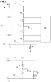
- Fig. 1 is a view showing an exemplary basic configuration of an electric leakage detecting device according to an embodiment of the present invention.
- the term "electric leakage detecting device” herein used means a circuit in which breeder current flows at a normal time and sensitivity current flows in the event of electrical leakage. However, it does not mean a circuit such as an electric leakage circuit breaker, in which sensitivity current is used to determine occurrence of electric leakage or to determine to turn off power supply.
- the electric leakage detecting device is connected between a pair of power lines L1 and L2, which is a system power supply (not shown in the figures) typically supplying alternating current (AC).
- a system power supply typically supplying alternating current (AC).
- AC alternating current
- the electric leakage detecting devices are disposed between each pair of phases.
- the power lines L1 and L2 may respectively be cathode and anode, or vise versa.
- the electric leakage detecting device of the present invention is designed to be disposed in parallel with the power source.
- the electric leakage detecting device has a first resistor circuit C1 and a second resistor circuit C2 which are connected between the power lines L1 and L2 in a serial alignment.
- the first resistor circuit C1 has a varistor element VR1, which is a constant voltage device, and a resistor device R1 in serial connection with each other.
- the resistor device R1 is a linear resistor device.
- the second resistor circuit C2 has a varistor element VR2, which is a constant voltage device, and a resistor device R2 in serial connection with each other.
- the resistor device R2 is a linear resistor device.
- the connection point N between the first resistor circuit C1 and the second resistor circuit C2 is grounded.
- the varistor elements have a high resistance value when voltage not higher than a predetermined varister voltage is applied thereto and scarcely pass electric current therethrhough.
- the varistor elements get to have a low resistance value when voltage higher than the varister voltage is applied thereto so as to maintain the end-to-end voltage thereof to be the varister voltage.
- the varistor elements work on electric current in both directions and withstand voltage of several hundred Volts and are adaptively used for high voltage DC power source.
- Fig. 2(a) Shown in Fig. 2(a) is a situation in the electric leakage detecting device shown in Fig. 1 that the power lines L1 and L2 respectively have potentials of +Vi and -Vi. This means that the voltage between the power lines L1 and L2 is 2Vi.
- Fig. 2(a) is a view schematically showing a situation that electric leakage has occurred on a power line in the electric leakage detecting device shown in Fig. 1 (The dotted lines indicates the negative side of the circuit where electric leakage has occurred.). The point in which electric leakage has occurred is indicated as a ground fault resistor Rs, which is located between the power line L2 and the grounding point G.
- Rs ground fault resistor
- the ground fault resistor Rs has a resistance value which is substantially lower than the that of the first resistor circuit C1 and the second resistor circuit C2, or almost zero. For ease of explanation, it is hereinafter assumed that the resistance value of the ground fault resistor Rs is zero. Also shown in the figure is an electric leakage determining unit 10, which may be configured arbitrarily.
- the first resistor circuit C1 and the second resistor circuit C2 each has an end-to-end voltage of Vi, given the potentials +Vi and -Vi of the power lines L1 and L2 respectively.
- Fig. 2(b) is a view showing an comparative example of an electric leakage detecting device.
- this comparative example there is no varistor element between the power lines L1 and L2, but two linear resistor devices Ro are disposed in serial alignment with each other with the connecting point therebetween grounded.
- the linear resistor devices Ro each has an end-to-end voltage of Vi.
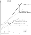
- Fig. 3 is a characteristic diagram showing the V-I characteristics which indicate the relationships between the end-to-end voltage V of the resistor device on the positive side (i.e. the first resistor circuit C1) and the current I respectively in the embodiment of Fig. 2(a) and the comparative example of Fig. 2(b) , and respectively at a normal time and in the event of electrical leakage.
- the circuit of the embodiment become effective when the end-to-end voltage V of the first resistor circuit is higher than the varister voltage V vr (V>V vr ). Since the end-to-end voltage V vr of the varister element VR1 is substantially constant regardless of change of the voltage V, the below relationship is assumed, defining the end-to-end voltage of the resistor device R1 as V r1 .
- V r 1 V ⁇ V Vr
- the end-to-end voltage V r1 of the resistor device R1 becomes Vi-V vr .
- the current which flows through the first resistor circuit C1 at a normal time which is the breeder current
- the current which flows through the first resistor circuit C1 at a normal time which is the breeder current
- the resistor device R1 has a lower resistance value than the resistor device Ro
- the power consumption IR 2 of caused by the breeder current is substantially lower than that in the comparative example.
- the breeder currents I n and I no in the embodiment and the comparative example at a normal time are respectively 10mA and 15mA.
- the present device should be made to operate in this range by adaptively setting the varister voltage and the resistance value of the resistor device with respect to the voltage of the power source.
- Fig. 2(a) shows a situation that electric leakage has occurred. Assuming that the end-to-end voltage of the second resistor circuit C2 has becomes zero, that of the first resistor circuit C1 becomes 2Vi. Similarly in the comparative example, the end-to-end voltage of the resistor device Ro on the positive side becomes 2Vi.
- the relationship between the end-to-end voltage V of the resistor device on the positive side (i.e. the first resistor circuit C1) and the current I so in the event of electrical leakage is represented by the below formula (3), which represents a line having a double inclination compared to the formula (1).
- V r 1 2 V ⁇ V Vr
- the end-to-end voltage V r1 of the resistor device R1 becomes 2Vi-V vr .
- the current which flows through the first resistor circuit C1 in the event of electrical leakage which is the sensitivity current
- the sensitivity current which flows through the resistor device R1 is made higher, the sensitivity for detecting electric leakage is lowered and the influence of noise is reduced.
- the same parameters are assumed as those at a normal time as described in the above.
- the sensitivity currents I s and I so in the embodiment and the comparative example at a normal time are respectively 40mA and 30mA.
- the present device should be made to operate in this range by adaptively setting the varister voltage and the resistance value of the resistor device with respect to the voltage of the power source.
- the electric leakage detecting device of the present invention having the interposing varistor elements VR1 and VR2 in serial alignment is capable of lowering the resistance values of the resistor devices R1 and R2 and yet lowering the breeder current at a normal time compared to the device of the comparative example not having varistor elements .
- the electric leakage detecting device of the present invention is also capable of lowering the sensitivity current in the event of electrical leakage as the resistance values of the resistor devices R1 and R2 is low.
- Fig. 4 is a view showing another configuration of an electric leakage detecting device according to an embodiment of the present invention.
- each pair of Zener diodes are serially connected and each has polarity opposite to the other so as to be adapted for AC power sources.
- each pair of Zener diodes can be replaced with one Zener diode having polarity opposite to the voltage of the power source. Zener diodes are preferably used in case the voltage of the power source is relatively low.
Landscapes
- Physics & Mathematics (AREA)
- General Physics & Mathematics (AREA)
- Engineering & Computer Science (AREA)
- Power Engineering (AREA)
- Testing Of Short-Circuits, Discontinuities, Leakage, Or Incorrect Line Connections (AREA)
- Emergency Protection Circuit Devices (AREA)
Applications Claiming Priority (2)
| Application Number | Priority Date | Filing Date | Title |
|---|---|---|---|
| JP2016055920A JP6678051B2 (ja) | 2016-03-18 | 2016-03-18 | 漏電検出装置 |
| PCT/JP2017/009474 WO2017159535A1 (ja) | 2016-03-18 | 2017-03-09 | 漏電検出装置 |
Publications (3)
| Publication Number | Publication Date |
|---|---|
| EP3432011A1 true EP3432011A1 (de) | 2019-01-23 |
| EP3432011A4 EP3432011A4 (de) | 2019-12-04 |
| EP3432011B1 EP3432011B1 (de) | 2026-01-14 |
Family
ID=59852245
Family Applications (1)
| Application Number | Title | Priority Date | Filing Date |
|---|---|---|---|
| EP17766536.1A Active EP3432011B1 (de) | 2016-03-18 | 2017-03-09 | Elektrische leckdetektionsvorrichtung |
Country Status (6)
| Country | Link |
|---|---|
| US (1) | US10746808B2 (de) |
| EP (1) | EP3432011B1 (de) |
| JP (1) | JP6678051B2 (de) |
| KR (1) | KR102325909B1 (de) |
| CN (1) | CN109073696B (de) |
| WO (1) | WO2017159535A1 (de) |
Cited By (1)
| Publication number | Priority date | Publication date | Assignee | Title |
|---|---|---|---|---|
| US20190162770A1 (en) * | 2016-03-18 | 2019-05-30 | Ntn Corporation | Electric leakage detection device |
Families Citing this family (4)
| Publication number | Priority date | Publication date | Assignee | Title |
|---|---|---|---|---|
| CN111366874B (zh) * | 2018-12-25 | 2025-04-08 | 兆易创新科技集团股份有限公司 | 漏电检测电路、闪存存储器漏电检测装置和漏电检测方法 |
| CN113820544B (zh) * | 2021-10-11 | 2024-07-26 | 湖南小快智造电子科技有限公司 | 对地阻抗测量电路、对地阻抗测量方法 |
| DE102023206991A1 (de) | 2023-07-24 | 2025-01-30 | Robert Bosch Gesellschaft mit beschränkter Haftung | Elektronische Schaltung zur Zustandsüberwachung spannungsabhängiger Widerstandsbauelemente |
| JP7659789B1 (ja) | 2024-01-12 | 2025-04-10 | 株式会社ニプロン | 地絡検出器 |
Family Cites Families (24)
| Publication number | Priority date | Publication date | Assignee | Title |
|---|---|---|---|---|
| US3848159A (en) * | 1973-06-18 | 1974-11-12 | Airpax Electronics | Ground fault detector circuit with feedback to sensor |
| JPS50127630U (de) * | 1974-04-02 | 1975-10-20 | ||
| US3978400A (en) * | 1974-11-25 | 1976-08-31 | Square D Company | Ground fault detector with a nonlinear sensing means |
| JPS5649231Y2 (de) * | 1975-07-25 | 1981-11-17 | ||
| JP2802970B2 (ja) * | 1991-05-21 | 1998-09-24 | 新電元工業株式会社 | プレ−ナ型二端子双方向性サイリスタ |
| JP4221623B2 (ja) * | 1997-09-12 | 2009-02-12 | 神保電器株式会社 | ノイズ・フィルタ回路 |
| KR20030010582A (ko) * | 2000-02-22 | 2003-02-05 | 산요 덴키 가부시키가이샤 | 전원 장치의 누전 검출 회로 |
| JP3594562B2 (ja) | 2001-03-30 | 2004-12-02 | 三洋電機株式会社 | 電源装置の漏電検出回路 |
| JP4053501B2 (ja) * | 2004-01-13 | 2008-02-27 | ファナック株式会社 | モータ駆動装置 |
| US7623329B2 (en) * | 2005-01-04 | 2009-11-24 | Technology Research Corporation | Leakage current detection and interruption circuit with improved shield |
| JP4994149B2 (ja) * | 2007-08-14 | 2012-08-08 | シチズンホールディングス株式会社 | 物理量センサ |
| US7791850B2 (en) * | 2008-01-16 | 2010-09-07 | Jingzheng Chen | Ground fault circuit interrupter control circuit |
| JP2009261039A (ja) * | 2008-04-11 | 2009-11-05 | Ntt Data Intellilink Corp | 高圧直流給電接地回路及び高圧直流給電漏電遮断回路 |
| US8570181B2 (en) * | 2010-03-15 | 2013-10-29 | Siemens Industry, Inc. | Method and apparatus for supervisory circuit for ground fault circuit interrupt device |
| BRPI1003307A2 (pt) * | 2010-05-21 | 2012-02-07 | Furnas Centrais Elétricas S.A. | dispositivo, sistema e método para monitoramento de linhas de eletrodos de aterramento |
| US20120212864A1 (en) * | 2011-02-21 | 2012-08-23 | Elms Robert T | Fail-safe ground fault circuit interrupter |
| WO2012164073A1 (fr) * | 2011-06-01 | 2012-12-06 | Commissariat à l'énergie atomique et aux énergies alternatives | Detection d'un defaut d'isolement |
| JP5414777B2 (ja) * | 2011-12-22 | 2014-02-12 | 株式会社正興電機製作所 | 直流回路の地絡検出装置および方法 |
| KR101247208B1 (ko) * | 2012-08-07 | 2013-03-26 | 엠티엔시 (주) | 누전 차단 장치 |
| US20140098446A1 (en) * | 2012-09-22 | 2014-04-10 | Victor V. Aromin | Universal Ground Fault Interrupter (GFCI) Device and Printed Circuit Board Package |
| US9225159B2 (en) * | 2012-12-19 | 2015-12-29 | Littelfuse, Inc. | Three-phase ground fault circuit interrupter |
| US9385489B2 (en) * | 2013-06-26 | 2016-07-05 | Calvin Wang | Adjustable electrical-power outlet strip |
| JP6678051B2 (ja) * | 2016-03-18 | 2020-04-08 | Ntn株式会社 | 漏電検出装置 |
| WO2018131797A1 (ko) * | 2017-01-11 | 2018-07-19 | 주식회사 나은에너지 | 배전계통 전원선로 고장시 실시간 탐지/복구시스템 및 그 공사방법 |
-
2016
- 2016-03-18 JP JP2016055920A patent/JP6678051B2/ja active Active
-
2017
- 2017-03-09 CN CN201780011994.9A patent/CN109073696B/zh active Active
- 2017-03-09 KR KR1020187022519A patent/KR102325909B1/ko active Active
- 2017-03-09 EP EP17766536.1A patent/EP3432011B1/de active Active
- 2017-03-09 US US16/086,237 patent/US10746808B2/en active Active
- 2017-03-09 WO PCT/JP2017/009474 patent/WO2017159535A1/ja not_active Ceased
Cited By (2)
| Publication number | Priority date | Publication date | Assignee | Title |
|---|---|---|---|---|
| US20190162770A1 (en) * | 2016-03-18 | 2019-05-30 | Ntn Corporation | Electric leakage detection device |
| US10746808B2 (en) * | 2016-03-18 | 2020-08-18 | Ntn Corporation | Electric leakage detection device |
Also Published As
| Publication number | Publication date |
|---|---|
| JP2017172992A (ja) | 2017-09-28 |
| JP6678051B2 (ja) | 2020-04-08 |
| EP3432011B1 (de) | 2026-01-14 |
| US20190162770A1 (en) | 2019-05-30 |
| EP3432011A4 (de) | 2019-12-04 |
| KR102325909B1 (ko) | 2021-11-11 |
| US10746808B2 (en) | 2020-08-18 |
| CN109073696B (zh) | 2021-02-05 |
| CN109073696A (zh) | 2018-12-21 |
| WO2017159535A1 (ja) | 2017-09-21 |
| KR20180122601A (ko) | 2018-11-13 |
Similar Documents
| Publication | Publication Date | Title |
|---|---|---|
| EP3432011B1 (de) | Elektrische leckdetektionsvorrichtung | |
| JP3594562B2 (ja) | 電源装置の漏電検出回路 | |
| JPWO2001063306A1 (ja) | 電源装置の漏電検出回路 | |
| EP2541715A1 (de) | Schaltung zur Erkennung von Störungen bei der Gleichstromversorgungsisolierung | |
| CN107703414A (zh) | 检测电路及检测方法 | |
| JP2015103699A (ja) | 太陽電池ストリングの異常検出方法、異常検出装置および太陽光発電装置 | |
| DE3923981A1 (de) | Verfahren und anordnungen zum pruefen von teilnehmerleitungsschleifen in fernsprechsystemen | |
| KR101671087B1 (ko) | 시퀀서 아날로그 출력 유닛 | |
| US20180041164A1 (en) | Solar power generation system inspection method and inspection apparatus | |
| JP2007285833A (ja) | 接続異常検知装置、接続異常検知方法及び電気装置 | |
| JP7445894B2 (ja) | 漏電検出装置 | |
| JP2016038357A (ja) | 直流地絡検出器 | |
| EP2837076B1 (de) | Monitor mit neutralem erdungswiderstand | |
| DE102016217712A1 (de) | Überwachungsvorrichtung und Verfahren zum Überwachen einer Impedanz eines Schutzleiters sowie Ladekontrolleinheit | |
| US20070103165A1 (en) | Ground testing method and apparatus | |
| JP6862122B2 (ja) | 直流地絡検出器 | |
| JP2016123232A (ja) | 太陽電池の検査方法およびその装置並びに太陽電池検査装置に用いられる信号源 | |
| JP2006145293A (ja) | 漏電検出装置 | |
| US20140306715A1 (en) | Missing or broken neutral monitoring circuit for split phase electrical distribution configurations | |
| CN114609544A (zh) | 一种直流供电系统接地故障分类诊断方法及装置 | |
| JP2014202696A (ja) | 漏電検出方法 | |
| US20250110073A1 (en) | Systems and methods for detecting and removing residue from low current electrical contacts | |
| JP7762902B2 (ja) | 直流電源の漏電検出装置 | |
| CN213689772U (zh) | 一种直流电源母线全静态接地电阻检测电路 | |
| CA2251542C (en) | Parallel termination apparatus and method for ground-check monitors |
Legal Events
| Date | Code | Title | Description |
|---|---|---|---|
| STAA | Information on the status of an ep patent application or granted ep patent |
Free format text: STATUS: THE INTERNATIONAL PUBLICATION HAS BEEN MADE |
|
| PUAI | Public reference made under article 153(3) epc to a published international application that has entered the european phase |
Free format text: ORIGINAL CODE: 0009012 |
|
| STAA | Information on the status of an ep patent application or granted ep patent |
Free format text: STATUS: REQUEST FOR EXAMINATION WAS MADE |
|
| 17P | Request for examination filed |
Effective date: 20181017 |
|
| AK | Designated contracting states |
Kind code of ref document: A1 Designated state(s): AL AT BE BG CH CY CZ DE DK EE ES FI FR GB GR HR HU IE IS IT LI LT LU LV MC MK MT NL NO PL PT RO RS SE SI SK SM TR |
|
| AX | Request for extension of the european patent |
Extension state: BA ME |
|
| DAV | Request for validation of the european patent (deleted) | ||
| DAX | Request for extension of the european patent (deleted) | ||
| A4 | Supplementary search report drawn up and despatched |
Effective date: 20191104 |
|
| RIC1 | Information provided on ipc code assigned before grant |
Ipc: G01R 27/02 20060101ALN20191028BHEP Ipc: H02H 3/16 20060101ALI20191028BHEP Ipc: G01R 27/18 20060101ALN20191028BHEP Ipc: G01R 31/02 20060101AFI20191028BHEP Ipc: G01R 31/00 20060101ALN20191028BHEP |
|
| STAA | Information on the status of an ep patent application or granted ep patent |
Free format text: STATUS: EXAMINATION IS IN PROGRESS |
|
| 17Q | First examination report despatched |
Effective date: 20221025 |
|
| REG | Reference to a national code |
Ref country code: DE Ref legal event code: R079 Free format text: PREVIOUS MAIN CLASS: G01R0031020000 Ipc: G01R0031520000 Ref country code: DE Ref legal event code: R079 Ref document number: 602017093529 Country of ref document: DE Free format text: PREVIOUS MAIN CLASS: G01R0031020000 Ipc: G01R0031520000 |
|
| GRAP | Despatch of communication of intention to grant a patent |
Free format text: ORIGINAL CODE: EPIDOSNIGR1 |
|
| STAA | Information on the status of an ep patent application or granted ep patent |
Free format text: STATUS: GRANT OF PATENT IS INTENDED |
|
| RIC1 | Information provided on ipc code assigned before grant |
Ipc: G01R 31/52 20200101AFI20250915BHEP |
|
| INTG | Intention to grant announced |
Effective date: 20251010 |
|
| GRAS | Grant fee paid |
Free format text: ORIGINAL CODE: EPIDOSNIGR3 |
|
| GRAA | (expected) grant |
Free format text: ORIGINAL CODE: 0009210 |
|
| STAA | Information on the status of an ep patent application or granted ep patent |
Free format text: STATUS: THE PATENT HAS BEEN GRANTED |
|
| AK | Designated contracting states |
Kind code of ref document: B1 Designated state(s): AL AT BE BG CH CY CZ DE DK EE ES FI FR GB GR HR HU IE IS IT LI LT LU LV MC MK MT NL NO PL PT RO RS SE SI SK SM TR |
|
| REG | Reference to a national code |
Ref country code: CH Ref legal event code: F10 Free format text: ST27 STATUS EVENT CODE: U-0-0-F10-F00 (AS PROVIDED BY THE NATIONAL OFFICE) Effective date: 20260114 Ref country code: GB Ref legal event code: FG4D |
|
| REG | Reference to a national code |
Ref country code: DE Ref legal event code: R096 Ref document number: 602017093529 Country of ref document: DE |