EP3431330B1 - Sitztiefenversteller - Google Patents
Sitztiefenversteller Download PDFInfo
- Publication number
- EP3431330B1 EP3431330B1 EP18181366.8A EP18181366A EP3431330B1 EP 3431330 B1 EP3431330 B1 EP 3431330B1 EP 18181366 A EP18181366 A EP 18181366A EP 3431330 B1 EP3431330 B1 EP 3431330B1
- Authority
- EP
- European Patent Office
- Prior art keywords
- base plate
- carrier plate
- depth adjuster
- seat depth
- spring
- Prior art date
- Legal status (The legal status is an assumption and is not a legal conclusion. Google has not performed a legal analysis and makes no representation as to the accuracy of the status listed.)
- Active
Links
Images


Classifications
-
- B—PERFORMING OPERATIONS; TRANSPORTING
- B60—VEHICLES IN GENERAL
- B60N—SEATS SPECIALLY ADAPTED FOR VEHICLES; VEHICLE PASSENGER ACCOMMODATION NOT OTHERWISE PROVIDED FOR
- B60N2/00—Seats specially adapted for vehicles; Arrangement or mounting of seats in vehicles
- B60N2/02—Seats specially adapted for vehicles; Arrangement or mounting of seats in vehicles the seat or part thereof being movable, e.g. adjustable
-
- B—PERFORMING OPERATIONS; TRANSPORTING
- B60—VEHICLES IN GENERAL
- B60N—SEATS SPECIALLY ADAPTED FOR VEHICLES; VEHICLE PASSENGER ACCOMMODATION NOT OTHERWISE PROVIDED FOR
- B60N2/00—Seats specially adapted for vehicles; Arrangement or mounting of seats in vehicles
- B60N2/62—Thigh-rests
-
- B—PERFORMING OPERATIONS; TRANSPORTING
- B60—VEHICLES IN GENERAL
- B60N—SEATS SPECIALLY ADAPTED FOR VEHICLES; VEHICLE PASSENGER ACCOMMODATION NOT OTHERWISE PROVIDED FOR
- B60N2/00—Seats specially adapted for vehicles; Arrangement or mounting of seats in vehicles
- B60N2/90—Details or parts not otherwise provided for
- B60N2/919—Positioning and locking mechanisms
- B60N2/929—Positioning and locking mechanisms linear
Definitions
- the invention relates to a seat depth adjuster according to the preamble of claim 1.
- Such seat depth adjusters are already known and used in a wide variety of forms and designs.
- DE 10 2009 018 754 A1 disclosed a vehicle seat with a seat depth adjustment.
- the object of the present invention is to overcome the disadvantages of the prior art.
- a seat depth adjuster is to be provided in which any rattling noises and grinding noises are eliminated.
- the handling should not be impaired.
- a seat depth adjuster according to the invention for a motor vehicle seat has a base plate and a carrier plate.
- the support plate is displaceable and fixable relative to the base plate, the support plate comprising a handle and the handle comprising a locking slider via a slide, the locking slider being insertable and extendable into a base plate toothing of the base plate.
- the locking slider has a tooth structure which can be brought into engagement with the toothing of the base plate toothing.
- All parts of the seat depth adjuster according to the invention can generally be produced from plastic. Even the energy store can be made available, for example, in the form of a rubber buffer. However, only a few parts can be made of plastic and the rest of metal.
- the locking slider comprises the energy store, the energy store in the working position pressing the locking slider into the base plate toothing and thereby producing a blockage that can be overcome manually by actuating the handle in conjunction with the slide. Pressing the locking conductor plate teeth is advantageously achieved that no unnecessary play between the components are more present and any noises such as rattling or squeaking are avoided.
- energy accumulator encompasses any type of spring element or rubber buffers that can absorb and release force in any way by deforming.
- the slide has a slide spring.
- This slide spring is used to ensure that the handle is always returned to its starting position if it was operated manually.
- the slide spring is arranged at a right angle to the energy store.
- two components are used.
- a leg spring can also be used, which could replace the two components. The forces would still act at right angles to one another, but only a single component would be required.
- the base plate and the carrier plate can be moved relative to one another via a rail system.
- the rail system consists of a tongue and groove construction, with either the carrier plate having the groove and the base plate having the tongue or, conversely, the base plate having the groove and the carrier plate having the tongue.
- the two components are arranged to be displaceable in relation to one another in defined paths in order to be able to move the carrier plate into the hollow of the knee of the user of the motor vehicle seat if necessary.
- the base plate also has fastening openings or fastening elements for fastening to the motor vehicle seat. As a rule, the base plate is firmly connected to the vehicle seat, whereas the carrier plate can be moved out of the circumference of the vehicle seat.
- Spring sliding elements are arranged between the base plate and the carrier plate. These spring sliding elements are used for better mobility the base plate to the carrier plate. They should prevent unwanted wedging. Furthermore, spring adjusters are provided for better handling of the seat depth adjuster according to the invention.
- the locking slider can also have an energy storage device, the energy storage device positioning and holding the energy storage device. This could be the case, for example, if there is an annular spring that represents the energy storage device. In such a case, for example, the energy storage receptacle could be a rod element on which the annular spring is drawn.
- the locking slider is also designed as part of the slide. This can mean, for example, that the locking slider is formed in one piece with the slide. However, it can also mean that the locking slider is an independent part which is connected to the slide via a fastening structure or a plug-in structure.
- the slide is hooked into the hooking arms of the carrier plate at one end via the handle and protrudes between the carrier plate and the base plate at the other end. It is provided that the slide is arranged such that it can be moved, for example, in a recess between the carrier plate and the base plate, with a further rail system also being conceivable that defines the movement of the slide.
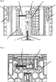
- Figure 1 is a plan view of a seat depth adjuster according to the invention for a motor vehicle seat.
- a carrier plate 1 is shown there.
- This carrier plate 1 has a honeycomb structure that consists largely of hexagonal honeycombs.
- the carrier plate 1 has a linear base side, towards which two side flanks incline slightly more than 90 ° and pass over a slightly convex front side extending approximately parallel to the base side away from the base side.
- a handle 2 is shown on this front side.
- part of the carrier plate 1 is highlighted as section A and shown in FIG Figure 4 shown enlarged again.
- an energy store 11 and a locking slider 5 are shown.
- the energy store 11 is a conventional spring.
- FIG 2 shows an exploded view of the seat depth adjuster according to the invention.
- a base plate 10 can be seen there in addition to the carrier plate 1.
- This base plate 10 has a base plate toothing 12, the base plate toothing 12 being formed in one piece as part of the base plate 10.
- two spring adjusters 8, 9 are shown.
- the base plate 10 has a groove construction 14 in which tongues of the carrier plate 1, not shown in detail, engage.
- This tongue and groove construction represents the rail system that enables the carrier plate 1 to be moved to the base plate 10.
- hooking arms 13 can be seen which protrude from the carrier plate 1 at a right angle. These hooking arms 13 have corresponding receptacles into which the handle 2 can be introduced together with the slide 3. The interaction of the handle 2 and the slide 3 enables the slide 3 to push the carrier plate 1 away from the base plate 10 by actuating the handle 2.
- the slide 3 also comprises a slide spring 4 and the locking slide 5.
- handle 2 is operated on the seat depth adjuster.
- the handle 2 executes a linear movement of the slide 3, as a result of which the locking slider 5 moves into the base plate toothing 12 of the base plate 1.
- the play in the base plate toothing 12 creates play in the longitudinal direction of the seat depth adjuster, which could otherwise generate noises.
- the energy store 11 which in this exemplary embodiment is a simple compression spring
- the The locking slider 5 presses into the base plate teeth 12. This advantageously means that the play in the longitudinal direction and the development of noise are significantly reduced.
- the spring force of the energy store is adapted to the respective requirements so that there is no excessive positive fit, but noise and play are avoided.
- Figure 3 is a plan view of a seat depth adjuster without representation of the support plate 1 and the handle 2 shown there is how the locking glider 5 engages in the base plate teeth 12 through the energy storage device 11.
- this engagement does not generate such a high pressure that when the slide 3 is actuated away from the energy store 11, the locking slide 5 cannot be moved linearly together with the slide 3 in the base plate toothing 12.
- a leg spring or a torsion spring can be provided instead of the energy store 11 and the slide spring 4.
- This leg spring can then easily replace the two components, the leg spring nevertheless on the one hand pushing the locking slider 5 into the base plate teeth 12 and on the other hand pushing the slide 3 back again and again into the starting position.
Landscapes
- Engineering & Computer Science (AREA)
- Aviation & Aerospace Engineering (AREA)
- Transportation (AREA)
- Mechanical Engineering (AREA)
- Seats For Vehicles (AREA)
Description
- Die Erfindung betrifft einen Sitztiefenversteller nach dem Oberbegriff des Anspruchs 1.
- Derartige Sitztiefenversteller sind bereits in vielfältiger Form und Ausgestaltung bekannt und gebräuchlich. So wird beispielsweise in der
DE 10 2009 018 754 A1 ein Fahrzeugsitz mit einer Sitztiefenverstellung offengelegt. - Daneben wird auf die
DE 10 2011 054 927 A1 hingewiesen, wo eine Sitztiefenverstellung für einen Fahrzeugsitz offenbart ist. - Weiter wird auf die
US 2007/108817 A1 hingewiesen, welche einen Sitztiefenvertseller für einen Kraftfahrzeugsitz mit einer Grundplatte und eine Trägerplatte beschreibt, wobei die Trägerplatte gegenüber der Grundplatte verschiebbar und festlegbar ist, wobei die Trägerplatte einen Griff umfasst und der Griff über einen Schieber einen Verriegelungsgleiter umfasst, wobei der Verriegelungsgleiter in eine Grundplattenverzahnung der Grundplatte einschiebbar und ausziehbar ist. - Auch wird auf die
DE 20 2016 107 014 U1 verwiesen, welche eine Trägerplatte für einen Sitztiefenversteller offenbart, wobei ein Aufnahmeelement zur Aufnahme eines Befestigungselementes vorhanden ist. - Die Aufgabe der vorliegenden Erfindung ist es, die Nachteile aus dem Stand der Technik zu überwinden. Insbesondere soll ein Sitztiefenversteller bereitgestellt werden, bei dem jegliche Klappergeräusche und Schleifgeräusche abgestellt sind. Dabei soll aber die Handhabbarkeit nicht beeinträchtigt werden.
- Zur Lösung der Aufgabe führen die Merkmale nach dem Anspruch 1.
- Vorteilhafte Ausgestaltungen sind in den Unteransprüchen beschrieben.
- Ein erfindungsgemäßer Sitztiefenversteller für einen Kraftfahrzeugsitz weist eine Grundplatte und eine Trägerplatte auf. Dabei ist die Trägerplatte gegenüber der Grundplatte verschiebbar und festlegbar, wobei die Trägerplatte einen Griff umfasst und der Griff über einen Schieber einen Verriegelungsgleiter umfasst, wobei der Verriegelungsgleiter in eine Grundplattenverzahnung der Grundplatte einschiebbar und ausziehbar ist. Der Verriegelungsgleiter weist dabei eine Zahnstruktur auf, welche mit der Verzahnung der Grundplattenverzahnung in Eingriff bringbar ist.
- Sämtliche Teile des erfindungsgemäßen Sitztiefenverstellers sind in der Regel aus Kunststoff herstellbar. Selbst der Kraftspeicher kann beispielsweise in Form eines Gummipuffers zur Verfügung gestellt werden. Es können aber auch nur ein paar Teile aus Kunststoff und der Rest aus Metall hergestellt sein.
- Der Verriegelungsgleiter umfasst den Kraftspeicher, wobei der Kraftspeicher in Arbeitslage den Verriegelungsgleiter in die Grundplattenverzahnung drückt und dadurch eine manuell durch Betätigen des Griffs in Zusammenhang mit dem Schieber überwindbare Blockade herstellt. Andrücken des Verriegelungsleiters Plattenverzahnung wird vorteilhaft erreicht, dass kein unnötiges Spiel zwischen den Bauteilen mehr vorhanden ist und etwaige Geräusche, wie beispielsweise Klappern oder Quietschen vermieden werden.
- Der Begriff des Kraftspeichers umfasste jegliche Art von Federelementen oder auch Gummipuffern, die in irgendeiner Art und Weise Kraft aufnehmen und wieder abgeben können indem sie sich verformen.
- Der Schieber weist eine Schieberfeder auf. Diese Schieberfeder dient dazu, dass der Griff immer wieder in die Ausgangsposition zurückgebracht wird, wenn er manuell betätigt wurde. Die Schieberfeder ist in einem rechten Winkel zu dem Kraftspeicher angeordnet. In diesem Ausführungsbeispiel wird von zwei Komponenten gesprochen. Allerdings kann anstatt der der Schieberfeder und dem Kraftspeicher auch eine Schenkelfeder eingesetzt werden, die die beiden Komponenten ersetzen könnte. Die Kräfte würden nach wie vor im rechten Winkel zueinander wirken, jedoch würde lediglich ein einziges Bauteil benötigt.
- Die Grundplatte und die Trägerplatte sind über ein Schienensystem zueinander verschiebbar. Das Schienensystem besteht ihren bevorzugten Ausführungsbeispiel aus einer Nut-Federkonstruktion, wobei entweder die Trägerplatte die Nut und die Grundplatte die Feder oder andersherum die Grundplatte die Nut die Trägerplatte die Feder aufweisen. Letztendlich kommt es hierbei nur darauf an, dass die beiden Bauteile in definierten Bahnen zueinander verschiebbar angeordnet sind, um die Trägerplatte bei Bedarf in die Kniekehle des Nutzers des Kraftfahrzeugsitzes verschieben zu können.
- Die Grundplatte weist außerdem Befestigungsöffnungen oder Befestigungselemente zur Befestigung an dem Kraftfahrzeugsitz auf. In der Regel ist die Grundplatte mit dem Fahrzeugsitz fest verbunden, wohingegen die Trägerplatte aus dem Umfang des Fahrzeugsitzes heraus bewegbar ist.
- Zwischen der Grundplatte und der Trägerplatte sind Federgleitelemente angeordnet. Diese Federgleitelemente dienen der besseren Verschiebbarkeit der Grundplatte zu der Trägerplatte. Sie sollen ein ungewolltes Verkeilen verhindern. Weiter sind zur besseren Handhabbarkeit des erfindungsgemässen Sitztiefenverstellers Federversteller vorgesehen.
- Der Verriegelungsgleiter kann ausserdem eine Kraftspeicheraufnahme aufweise, wobei die Kraftspeicheraufnahme den Kraftspeicher positioniert und hält. Das könnte beispielsweise dann der Fall sein, wenn eine Ringfeder vorhanden ist, die den Kraftspeicher darstellt. In einem solchen Fall könnte beispielsweise die Kraftspeicheraufnahme ein Stabelement sein, auf welches die Ringfeder aufgezogen ist.
- Der Verriegelungsgleiter ist außerdem als Teil des Schiebers ausgebildet. Das kann beispielsweise bedeuten, dass der Verriegelungsgleiter einstückig mit dem Schieber ausgebildet ist. Es kann aber auch bedeuten, dass der Verriegelungsgleiter ein eigenständiges Teil ist, welches über eine Befestigungskonstruktion oder Steckkonstruktion mit dem Schieber verbunden ist.
- Der Schieber ist einends über den Griff in den Einhakarmen der Trägerplatte eingehängt und ragt andernends zwischen die Trägerplatte und die Grundplatte. Dabei ist vorgesehen, dass der Schieber beispielsweise in eine Ausnehmung zwischen Trägerplatte und Grundplatte bewegbar angeordnet ist, wobei auch ein weiteres Schienensystem denkbar ist, dass die Bewegung des Schiebers definiert.
- Weitere Vorteile, Merkmale und Einzelheiten der Erfindung ergeben sich aus der nachfolgenden Beschreibung bevorzugter Ausführungsbeispiele sowie anhand der Zeichnungen; diese zeigen in:
- Figur 1
- eine Draufsicht auf einen Sitztiefenversteller;
- Figur 2
- eine Explosionsdarstellung des Sitztiefenverstellers;
- Figur 3
- Draufsicht auf einen Sitztiefenversteller ohne Trägerplatte ohne Betätigungsgriff;
- Figur 4
- einen vergrößerten Ausschnitt eines Teils der
Figur 1 . - In
Figur 1 ist eine Draufsicht eines erfindungsgemässen Sitztiefenverstellers für einen Kraftfahrzeugsitz dargestellt. Dort ist eine Trägerplatte 1 gezeigt. Diese Trägerplatte 1 weist eine Wabenstruktur auf, die größtenteils aus sechseckigen Waben besteht. Die Trägerplatte 1 weist eine lineare Grundseite auf, zu der sich zwei Seitenflanken leicht über 90° wegneigen und über eine etwa parallel zur Grundseite verlaufende von der Grundseite weg leicht konvexe Frontseite übergehen. - An dieser Frontseite ist ein Griff 2 gezeigt. Außerdem ist ein Teil der Trägerplatte 1 als Ausschnitt A hervorgehoben und in
Figur 4 nochmals vergrößert dargestellt. In diesem Ausschnitt A sind ein Kraftspeicher 11 und ein Verriegelungsgleiter 5 gezeigt. In diesem Ausführungsbeispiel ist der Kraftspeicher 11 eine herkömmliche Feder. - In der
Figur 2 ist eine Explosionsdarstellung des erfindungsgemäßen Sitztiefenverstellers gezeigt. Dort ist neben der Trägerplatte 1 eine Grundplatte 10 zu erkennen. Diese Grundplatte 10 weist eine Grundplattenverzahnung 12 auf, wobei die Grundplattenverzahnung 12 einstückig als Teil der Grundplatte 10 ausgeformt ist. Weiter sind inFigur 2 zwei Federversteller 8, 9 gezeigt. Weiter sind zwei Federgleitelemente 6, 7 vorhanden. - Die Grundplatte 10 weist eine Nutkonstruktion 14 auf, in welchen nicht näher gezeigte Federn der Trägerplatte 1 eingreifen. Diese Nut-Federkonstruktion stellt das Schienensystem dar, dass ein Verschieben der Trägerplatte 1 zu der Grundplatte 10 ermöglichen.
- Weiterhin sind zwei Einhakarme 13 zu erkennen, welche im rechten Winkel von der Trägerplatte 1 wegragen. Diese Einhakarme 13 weisen entsprechende Aufnahmen auf, in welche der Griff 2 gemeinsam mit dem Schieber 3 eingebracht werden können. Durch das Zusammenspiel des Griffs 2 und des Schieber 3 wird ermöglicht, dass durch Betätigen des Griffs 2 der Schieber 3 die Trägerplatte 1 von der Grundplatte 10 wegschiebt. Der Schieber 3 umfasst außerdem eine Schieberfeder 4 und den Verriegelungsgleiter 5.
- Zum Ver- und Entriegeln wird am Sitztiefenversteller der Griff 2 betätigt. Der Griff 2 führt eine lineare Bewegung des Schiebers 3 aus, wodurch der Verriegelungsgleiter 5 in die Grundplattenverzahnung 12 der Grundplatte 1 hinein verfährt. Dabei findet kein vollständiger Formschluss statt, um keine zu hohen Entriegelungskräfte entstehen zu lassen, welche durch die größeren Freiflächen innerhalb der Grundplattenverzahnung 12 ansonsten entstehen würden. Durch das Spiel in der Grundplattenverzahnung 12 entsteht ein Spiel in Längsrichtung des Sitztiefenverstellers, wodurch sich ansonsten Geräusche entwickeln könnten.
- Dies wird erfinderisch vorteilhaft dadurch gelöst, dass der Kraftspeicher 11, was in diesem Ausführungsbeispiel eine einfache Druckfeder ist, den Verriegelungsgleiter 5 in die Grundplattenverzahnung 12 eindrückt. Dadurch wird vorteilhaft erreicht, dass das Spiel in Längsrichtung und die Geräuschentwicklung wesentlich reduziert wird. Dabei wird die Federkraft des Kraftspeichers den jeweiligen Erfordernissen angepasst, sodass kein zu großer Formschluss entsteht, aber trotzdem Geräuschentwicklung und Spiel vermieden werden.
- In
Figur 3 ist eine Draufsicht auf einen Sitztiefenversteller ohne Darstellung der Trägerplatte 1 und des Griffs 2 gezeigt dort ist zu erkennen, wie der Verriegelungsgleiter 5 durch den Kraftspeicher 11 in die Grundplattenverzahnung 12 eingreift. Durch dieses Eingreifen wird aber kein derart hoher Druck erzeugt, dass bei betätigen des Schieber 3 Weg vom Kraftspeicher 11 der Verriegelungsgleiter 5 nicht linear gemeinsam mit dem Schieber 3 in der Grundplattenverzahnung 12 bewegbar wäre. - In
Figur 4 ist der Ausschnitt A nochmals vergrößert dargestellt. Dort ist zu erkennen, wie der Kraftspeicher 11 in Arbeitslage den Verriegelungsgleiter 5 in die hier nicht näher gezeigte Grundplattenverzahnung 12 drückt. - In einem anderen nicht gezeigten Ausführungsbeispiel kann anstatt des Kraftspeichers 11 und der Schieberfeder 4 eine Schenkelfeder bzw. eine Drehfeder vorgesehen sein. Diese Schenkelfeder kann dann auf einfache Weise die beiden Komponenten ersetzen, wobei trotzdem die Schenkelfeder einerseits den Verriegelungsgleiter 5 in die Grundplattenverzahnung 12 drückt und andererseits den Schieber 3 immer wieder in die Ausgangsposition zurückdrückt.
Bezugszeichenliste 1 Trägerplatte 2 Griff 3 Schieber 4 Schieberfeder 5 Verriegelungsgleiter 6 Federgleitelement 7 Federqleitelement 8 Federversteller 9 Federversteller 10 Grundplatte 11 Kraftspeicher 12 Grundplattenverzahnung 13 Einhakarme 14 Nutkonstruktion 15 16 17 18 19 20 21 22 23 24 A Ausschnitt
Claims (7)
- Sitztiefenversteller für einen Kraftfahrzeugsitz mit einer Grundplatte (10) und eine Trägerplatte (1), wobei die Trägerplatte (1) gegenüber der Grundplatte (10) verschiebbar und festlegbar ist, wobei die Trägerplatte (1) einen Griff (2) umfasst, wobei der Griff (2) über einen Schieber (3) einen Verriegelungsgleiter (5) umfasst, wobei der Verriegelungsgleiter (5) in eine Grundplattenverzahnung (12) der Grundplatte (10) einschiebbar und ausziehbar ist,
wobei der Verriegelungsgleiter (5) einen Kraftspeicher (11) oder eine Schenkelfeder umfasst, wobei der Kraftspeicher (11) oder die Schenkelfeder in Arbeitslage den Verriegelungsgleiter (5) in die Grundplattenverzahnung (12) drückt, wobei die Grundplatte (10) und die Trägerplatte (1) über ein Schienensystem zueinander verschiebbar sind, dadurch gekennzeichnet, dass zwischen der Grundplatte (10) und der Trägerplatte (1) Federgleitelemente (6, 7) angeordnet sind, wobei zur Verschiebbarkeit der Trägerplatte (1) zu der Grundplatte (10) Federversteller (8, 9) angeordnet sind. - Sitztiefenversteller nach Anspruch 1, dadurch gekennzeichnet, dass der Schieber (3) eine Schieberfeder (4) aufweist.
- Sitztiefenversteller nach Anspruch 2, dadurch gekennzeichnet, dass die Schieberfeder (4) in einem rechten Winkel zu dem Kraftspeicher (11) angeordnet ist.
- Sitztiefenversteller nach einem der vorigen Ansprüche, dadurch gekennzeichnet, dass die Grundplatte (10) Befestigungsöffnungen oder Befestigungselemente zur Befestigung an dem Kraftfahrzeugsitz aufweist.
- Sitztiefenversteller nach einem der vorigen Ansprüche, dadurch gekennzeichnet, dass der Verriegelungsgleiter (5) eine Kraftspeicheraufnahme aufweist, wobei die Kraftspeicheraufnahme den Kraftspeicher (11) positioniert und hält.
- Sitztiefenversteller nach einem der vorigen Ansprüche, dadurch gekennzeichnet, dass der Verriegelungsgleiter (5) als Teil des Schiebers (3) ausgebildet ist.
- Sitztiefenversteller nach einem der vorigen Ansprüche, dadurch gekennzeichnet, dass der Schieber (3) einends über den Griff (2) in Einhakarmen (13) der Trägerplatte (1) eingehängt ist und andernends zwischen die Trägerplatte (1) und die Grundplatte (10) ragt.
Applications Claiming Priority (1)
| Application Number | Priority Date | Filing Date | Title |
|---|---|---|---|
| DE102017116010.8A DE102017116010A1 (de) | 2017-07-17 | 2017-07-17 | Sitztiefenversteller |
Publications (2)
| Publication Number | Publication Date |
|---|---|
| EP3431330A1 EP3431330A1 (de) | 2019-01-23 |
| EP3431330B1 true EP3431330B1 (de) | 2020-09-02 |
Family
ID=62846032
Family Applications (1)
| Application Number | Title | Priority Date | Filing Date |
|---|---|---|---|
| EP18181366.8A Active EP3431330B1 (de) | 2017-07-17 | 2018-07-03 | Sitztiefenversteller |
Country Status (3)
| Country | Link |
|---|---|
| EP (1) | EP3431330B1 (de) |
| CN (1) | CN109263517B (de) |
| DE (1) | DE102017116010A1 (de) |
Family Cites Families (14)
| Publication number | Priority date | Publication date | Assignee | Title |
|---|---|---|---|---|
| US7578554B2 (en) * | 2005-11-17 | 2009-08-25 | Illinois Tool Works Inc. | Thigh extension system for a vehicle seat |
| DE102006018353B4 (de) * | 2006-04-19 | 2008-06-26 | Kochendörfer & Kiep Metallverarbeitung GmbH | Vorrichtung zur Verstellung der Sitztiefe eines Fahrzeugsitzes |
| DE202007002803U1 (de) * | 2007-02-23 | 2007-07-12 | Koki Technik Seating Systems Gmbh | Vorrichtung zur Verstellung der Sitztiefe eines Fahrzeuges |
| JP2009201763A (ja) * | 2008-02-28 | 2009-09-10 | Itoki Corp | 椅子 |
| DE102009018754B4 (de) | 2009-03-13 | 2014-04-10 | Kokinetics Gmbh | Fahrzeugsitz |
| DE102010011134B4 (de) * | 2010-03-11 | 2014-05-22 | Kokinetics Gmbh | Sitztiefenverstellung |
| DE102011054927B4 (de) | 2011-10-28 | 2021-03-18 | Kokinetics Gmbh | Sitztiefenverstellung für einen Fahrzeugsitz |
| FR2988046B1 (fr) * | 2012-03-13 | 2014-03-21 | Faurecia Sieges Automobile | Siege de vehicule comportant un nez d'assise |
| DE102013113304A1 (de) * | 2012-12-18 | 2014-06-18 | Kokinetics Gmbh | Vorrichtung zur Sitztiefenverstellung |
| DE102015201232A1 (de) * | 2015-01-26 | 2016-07-28 | Brose Fahrzeugteile Gmbh & Co. Kommanditgesellschaft, Coburg | Fahrzeugsitz |
| DE102015016487A1 (de) * | 2015-12-18 | 2017-06-22 | GM Global Technology Operations LLC (n. d. Gesetzen des Staates Delaware) | Verstellvorrichtung zur Verstellung einer Sitztiefe eines Fahrzeugsitzes, Fahrzeugsitz mit der Verstellvorrichtung und Verfahren zur Verstellung der Sitztiefe des Fahrzeugsitzes mit der Verstellvorrichtung |
| KR101685927B1 (ko) * | 2016-06-09 | 2016-12-13 | (주)디에스시 | 수동형 시트쿠션 익스텐션 장치 및 이를 포함하는 차량용 시트 |
| DE202016107014U1 (de) * | 2016-12-15 | 2017-02-06 | Kokinetics Gmbh | Trägerplatte und Grundplatte für einen Sitztiefenversteller, Sitztiefenversteller und Fahrzeugsitz |
| CN106864321B (zh) * | 2017-03-09 | 2023-11-14 | 安道拓(重庆)汽车部件有限公司 | 座椅腿托手动调节机构及汽车座椅 |
-
2017
- 2017-07-17 DE DE102017116010.8A patent/DE102017116010A1/de not_active Withdrawn
-
2018
- 2018-06-20 CN CN201810638992.9A patent/CN109263517B/zh active Active
- 2018-07-03 EP EP18181366.8A patent/EP3431330B1/de active Active
Non-Patent Citations (1)
| Title |
|---|
| None * |
Also Published As
| Publication number | Publication date |
|---|---|
| CN109263517B (zh) | 2021-10-26 |
| EP3431330A1 (de) | 2019-01-23 |
| CN109263517A (zh) | 2019-01-25 |
| DE102017116010A1 (de) | 2019-01-17 |
Similar Documents
| Publication | Publication Date | Title |
|---|---|---|
| EP2222202B1 (de) | Schubkasten mit Frontverstellung | |
| EP2750549B1 (de) | Schublade | |
| DE102014116169A1 (de) | Spannklaue zur Anbringung an einer Gleitschiene eines Operationstisches | |
| DE20106081U1 (de) | Lösemechanismus für eine Teleskopgleitschienenanordnung | |
| EP2497883B1 (de) | Ausziehsperrvorrichtung | |
| DE102007059744A1 (de) | Getriebebaueinheit einer Verstelleinrichtung eines Kraftfahrzeugs | |
| DE112013005896T5 (de) | Gleitstange für einen Fahrzeugsitz und Fahrzeugsitz umfassend eine solche Gleitstange | |
| DE102017113063A1 (de) | Tragschienenbefestigung | |
| EP1403109A2 (de) | Führungsschiene und Schlitten, insbesondere für ein Sonnenschutzrollo in einem Kraftfahrzeug | |
| DE102007042595A1 (de) | Verstelleinrichtung zur Längsverstellung einer Kraftfahrzeugkomponente | |
| DE102013004515A1 (de) | Einrichtung zum lösbaren Befestigen eines Montageteils | |
| DE102008012217A1 (de) | Verriegelungseinrichtung, insbesondere für eine crashaktive Kopfstütze eines Fahrzeugs | |
| DE202011108873U1 (de) | Vorrichtung zum Befestigen eines Moduls zur Nutzung von Sonnenenergie | |
| DE102016110496A1 (de) | Kopfstütze für einen Kraftfahrzeugsitz | |
| DE4005369C9 (de) | Schließeinrichtung an einer Fahrzeugtür | |
| DE102006043206B4 (de) | Schiebeblende/Rast-Feder-Käfig | |
| DE102014220476B4 (de) | Längsversteller mit Sperrmechanismus | |
| DE102019200488A1 (de) | Lenksäule für ein Kraftfahrzeug | |
| WO2016046025A1 (de) | Verstellvorrichtung für ein kraftfahrzeug | |
| WO2014131477A1 (de) | In seiner längsführung vorverlagerbarer fahrzeugsitz mit klappbarer rückenlehne | |
| DE102009018754A1 (de) | Fahrzeugsitz | |
| DE102014226133B4 (de) | Einstellvorrichtung für eine Rücksitzlehne | |
| WO2013087529A1 (de) | Sitztiefenverstellung, insbesondere für einen fahrzeugsitz | |
| EP2690017B1 (de) | Fixiervorrichtung für einen Ausstattungsgegenstand an einer Fixierschiene | |
| DE102011112305A1 (de) | Sitzanordnung für ein Kraftfahrzeug mit einer Zwangsführung für einen Fahrzeugsitz |
Legal Events
| Date | Code | Title | Description |
|---|---|---|---|
| PUAI | Public reference made under article 153(3) epc to a published international application that has entered the european phase |
Free format text: ORIGINAL CODE: 0009012 |
|
| STAA | Information on the status of an ep patent application or granted ep patent |
Free format text: STATUS: THE APPLICATION HAS BEEN PUBLISHED |
|
| AK | Designated contracting states |
Kind code of ref document: A1 Designated state(s): AL AT BE BG CH CY CZ DE DK EE ES FI FR GB GR HR HU IE IS IT LI LT LU LV MC MK MT NL NO PL PT RO RS SE SI SK SM TR |
|
| AX | Request for extension of the european patent |
Extension state: BA ME |
|
| STAA | Information on the status of an ep patent application or granted ep patent |
Free format text: STATUS: REQUEST FOR EXAMINATION WAS MADE |
|
| 17P | Request for examination filed |
Effective date: 20190618 |
|
| RBV | Designated contracting states (corrected) |
Designated state(s): AL AT BE BG CH CY CZ DE DK EE ES FI FR GB GR HR HU IE IS IT LI LT LU LV MC MK MT NL NO PL PT RO RS SE SI SK SM TR |
|
| RIC1 | Information provided on ipc code assigned before grant |
Ipc: B60N 2/90 20180101ALI20200130BHEP Ipc: B60N 2/62 20060101ALI20200130BHEP Ipc: B60N 2/02 20060101AFI20200130BHEP |
|
| GRAP | Despatch of communication of intention to grant a patent |
Free format text: ORIGINAL CODE: EPIDOSNIGR1 |
|
| STAA | Information on the status of an ep patent application or granted ep patent |
Free format text: STATUS: GRANT OF PATENT IS INTENDED |
|
| INTG | Intention to grant announced |
Effective date: 20200407 |
|
| GRAS | Grant fee paid |
Free format text: ORIGINAL CODE: EPIDOSNIGR3 |
|
| GRAA | (expected) grant |
Free format text: ORIGINAL CODE: 0009210 |
|
| STAA | Information on the status of an ep patent application or granted ep patent |
Free format text: STATUS: THE PATENT HAS BEEN GRANTED |
|
| AK | Designated contracting states |
Kind code of ref document: B1 Designated state(s): AL AT BE BG CH CY CZ DE DK EE ES FI FR GB GR HR HU IE IS IT LI LT LU LV MC MK MT NL NO PL PT RO RS SE SI SK SM TR |
|
| REG | Reference to a national code |
Ref country code: GB Ref legal event code: FG4D Free format text: NOT ENGLISH |
|
| REG | Reference to a national code |
Ref country code: AT Ref legal event code: REF Ref document number: 1308458 Country of ref document: AT Kind code of ref document: T Effective date: 20200915 Ref country code: CH Ref legal event code: EP |
|
| REG | Reference to a national code |
Ref country code: DE Ref legal event code: R096 Ref document number: 502018002323 Country of ref document: DE |
|
| REG | Reference to a national code |
Ref country code: IE Ref legal event code: FG4D Free format text: LANGUAGE OF EP DOCUMENT: GERMAN |
|
| REG | Reference to a national code |
Ref country code: LT Ref legal event code: MG4D |
|
| PG25 | Lapsed in a contracting state [announced via postgrant information from national office to epo] |
Ref country code: LT Free format text: LAPSE BECAUSE OF FAILURE TO SUBMIT A TRANSLATION OF THE DESCRIPTION OR TO PAY THE FEE WITHIN THE PRESCRIBED TIME-LIMIT Effective date: 20200902 Ref country code: HR Free format text: LAPSE BECAUSE OF FAILURE TO SUBMIT A TRANSLATION OF THE DESCRIPTION OR TO PAY THE FEE WITHIN THE PRESCRIBED TIME-LIMIT Effective date: 20200902 Ref country code: SE Free format text: LAPSE BECAUSE OF FAILURE TO SUBMIT A TRANSLATION OF THE DESCRIPTION OR TO PAY THE FEE WITHIN THE PRESCRIBED TIME-LIMIT Effective date: 20200902 Ref country code: BG Free format text: LAPSE BECAUSE OF FAILURE TO SUBMIT A TRANSLATION OF THE DESCRIPTION OR TO PAY THE FEE WITHIN THE PRESCRIBED TIME-LIMIT Effective date: 20201202 Ref country code: GR Free format text: LAPSE BECAUSE OF FAILURE TO SUBMIT A TRANSLATION OF THE DESCRIPTION OR TO PAY THE FEE WITHIN THE PRESCRIBED TIME-LIMIT Effective date: 20201203 Ref country code: NO Free format text: LAPSE BECAUSE OF FAILURE TO SUBMIT A TRANSLATION OF THE DESCRIPTION OR TO PAY THE FEE WITHIN THE PRESCRIBED TIME-LIMIT Effective date: 20201202 Ref country code: FI Free format text: LAPSE BECAUSE OF FAILURE TO SUBMIT A TRANSLATION OF THE DESCRIPTION OR TO PAY THE FEE WITHIN THE PRESCRIBED TIME-LIMIT Effective date: 20200902 |
|
| REG | Reference to a national code |
Ref country code: NL Ref legal event code: MP Effective date: 20200902 |
|
| PG25 | Lapsed in a contracting state [announced via postgrant information from national office to epo] |
Ref country code: RS Free format text: LAPSE BECAUSE OF FAILURE TO SUBMIT A TRANSLATION OF THE DESCRIPTION OR TO PAY THE FEE WITHIN THE PRESCRIBED TIME-LIMIT Effective date: 20200902 Ref country code: LV Free format text: LAPSE BECAUSE OF FAILURE TO SUBMIT A TRANSLATION OF THE DESCRIPTION OR TO PAY THE FEE WITHIN THE PRESCRIBED TIME-LIMIT Effective date: 20200902 Ref country code: PL Free format text: LAPSE BECAUSE OF FAILURE TO SUBMIT A TRANSLATION OF THE DESCRIPTION OR TO PAY THE FEE WITHIN THE PRESCRIBED TIME-LIMIT Effective date: 20200902 |
|
| PG25 | Lapsed in a contracting state [announced via postgrant information from national office to epo] |
Ref country code: EE Free format text: LAPSE BECAUSE OF FAILURE TO SUBMIT A TRANSLATION OF THE DESCRIPTION OR TO PAY THE FEE WITHIN THE PRESCRIBED TIME-LIMIT Effective date: 20200902 Ref country code: RO Free format text: LAPSE BECAUSE OF FAILURE TO SUBMIT A TRANSLATION OF THE DESCRIPTION OR TO PAY THE FEE WITHIN THE PRESCRIBED TIME-LIMIT Effective date: 20200902 Ref country code: PT Free format text: LAPSE BECAUSE OF FAILURE TO SUBMIT A TRANSLATION OF THE DESCRIPTION OR TO PAY THE FEE WITHIN THE PRESCRIBED TIME-LIMIT Effective date: 20210104 Ref country code: CZ Free format text: LAPSE BECAUSE OF FAILURE TO SUBMIT A TRANSLATION OF THE DESCRIPTION OR TO PAY THE FEE WITHIN THE PRESCRIBED TIME-LIMIT Effective date: 20200902 Ref country code: SM Free format text: LAPSE BECAUSE OF FAILURE TO SUBMIT A TRANSLATION OF THE DESCRIPTION OR TO PAY THE FEE WITHIN THE PRESCRIBED TIME-LIMIT Effective date: 20200902 |
|
| PG25 | Lapsed in a contracting state [announced via postgrant information from national office to epo] |
Ref country code: IS Free format text: LAPSE BECAUSE OF FAILURE TO SUBMIT A TRANSLATION OF THE DESCRIPTION OR TO PAY THE FEE WITHIN THE PRESCRIBED TIME-LIMIT Effective date: 20210102 Ref country code: AL Free format text: LAPSE BECAUSE OF FAILURE TO SUBMIT A TRANSLATION OF THE DESCRIPTION OR TO PAY THE FEE WITHIN THE PRESCRIBED TIME-LIMIT Effective date: 20200902 Ref country code: ES Free format text: LAPSE BECAUSE OF FAILURE TO SUBMIT A TRANSLATION OF THE DESCRIPTION OR TO PAY THE FEE WITHIN THE PRESCRIBED TIME-LIMIT Effective date: 20200902 |
|
| REG | Reference to a national code |
Ref country code: DE Ref legal event code: R097 Ref document number: 502018002323 Country of ref document: DE |
|
| PG25 | Lapsed in a contracting state [announced via postgrant information from national office to epo] |
Ref country code: SK Free format text: LAPSE BECAUSE OF FAILURE TO SUBMIT A TRANSLATION OF THE DESCRIPTION OR TO PAY THE FEE WITHIN THE PRESCRIBED TIME-LIMIT Effective date: 20200902 |
|
| PLBE | No opposition filed within time limit |
Free format text: ORIGINAL CODE: 0009261 |
|
| STAA | Information on the status of an ep patent application or granted ep patent |
Free format text: STATUS: NO OPPOSITION FILED WITHIN TIME LIMIT |
|
| 26N | No opposition filed |
Effective date: 20210603 |
|
| PG25 | Lapsed in a contracting state [announced via postgrant information from national office to epo] |
Ref country code: SI Free format text: LAPSE BECAUSE OF FAILURE TO SUBMIT A TRANSLATION OF THE DESCRIPTION OR TO PAY THE FEE WITHIN THE PRESCRIBED TIME-LIMIT Effective date: 20200902 Ref country code: DK Free format text: LAPSE BECAUSE OF FAILURE TO SUBMIT A TRANSLATION OF THE DESCRIPTION OR TO PAY THE FEE WITHIN THE PRESCRIBED TIME-LIMIT Effective date: 20200902 |
|
| PG25 | Lapsed in a contracting state [announced via postgrant information from national office to epo] |
Ref country code: IT Free format text: LAPSE BECAUSE OF FAILURE TO SUBMIT A TRANSLATION OF THE DESCRIPTION OR TO PAY THE FEE WITHIN THE PRESCRIBED TIME-LIMIT Effective date: 20200902 |
|
| REG | Reference to a national code |
Ref country code: CH Ref legal event code: PL |
|
| PG25 | Lapsed in a contracting state [announced via postgrant information from national office to epo] |
Ref country code: MC Free format text: LAPSE BECAUSE OF FAILURE TO SUBMIT A TRANSLATION OF THE DESCRIPTION OR TO PAY THE FEE WITHIN THE PRESCRIBED TIME-LIMIT Effective date: 20200902 |
|
| REG | Reference to a national code |
Ref country code: BE Ref legal event code: MM Effective date: 20210731 |
|
| PG25 | Lapsed in a contracting state [announced via postgrant information from national office to epo] |
Ref country code: LI Free format text: LAPSE BECAUSE OF NON-PAYMENT OF DUE FEES Effective date: 20210731 Ref country code: CH Free format text: LAPSE BECAUSE OF NON-PAYMENT OF DUE FEES Effective date: 20210731 |
|
| PG25 | Lapsed in a contracting state [announced via postgrant information from national office to epo] |
Ref country code: LU Free format text: LAPSE BECAUSE OF NON-PAYMENT OF DUE FEES Effective date: 20210703 Ref country code: FR Free format text: LAPSE BECAUSE OF NON-PAYMENT OF DUE FEES Effective date: 20210731 |
|
| PG25 | Lapsed in a contracting state [announced via postgrant information from national office to epo] |
Ref country code: IE Free format text: LAPSE BECAUSE OF NON-PAYMENT OF DUE FEES Effective date: 20210703 Ref country code: BE Free format text: LAPSE BECAUSE OF NON-PAYMENT OF DUE FEES Effective date: 20210731 |
|
| GBPC | Gb: european patent ceased through non-payment of renewal fee |
Effective date: 20220703 |
|
| PG25 | Lapsed in a contracting state [announced via postgrant information from national office to epo] |
Ref country code: GB Free format text: LAPSE BECAUSE OF NON-PAYMENT OF DUE FEES Effective date: 20220703 |
|
| PG25 | Lapsed in a contracting state [announced via postgrant information from national office to epo] |
Ref country code: NL Free format text: LAPSE BECAUSE OF NON-PAYMENT OF DUE FEES Effective date: 20200923 Ref country code: CY Free format text: LAPSE BECAUSE OF FAILURE TO SUBMIT A TRANSLATION OF THE DESCRIPTION OR TO PAY THE FEE WITHIN THE PRESCRIBED TIME-LIMIT Effective date: 20200902 |
|
| PG25 | Lapsed in a contracting state [announced via postgrant information from national office to epo] |
Ref country code: HU Free format text: LAPSE BECAUSE OF FAILURE TO SUBMIT A TRANSLATION OF THE DESCRIPTION OR TO PAY THE FEE WITHIN THE PRESCRIBED TIME-LIMIT; INVALID AB INITIO Effective date: 20180703 |
|
| PG25 | Lapsed in a contracting state [announced via postgrant information from national office to epo] |
Ref country code: MK Free format text: LAPSE BECAUSE OF FAILURE TO SUBMIT A TRANSLATION OF THE DESCRIPTION OR TO PAY THE FEE WITHIN THE PRESCRIBED TIME-LIMIT Effective date: 20200902 |
|
| REG | Reference to a national code |
Ref country code: AT Ref legal event code: MM01 Ref document number: 1308458 Country of ref document: AT Kind code of ref document: T Effective date: 20230703 |
|
| PG25 | Lapsed in a contracting state [announced via postgrant information from national office to epo] |
Ref country code: MT Free format text: LAPSE BECAUSE OF FAILURE TO SUBMIT A TRANSLATION OF THE DESCRIPTION OR TO PAY THE FEE WITHIN THE PRESCRIBED TIME-LIMIT Effective date: 20200902 |
|
| PG25 | Lapsed in a contracting state [announced via postgrant information from national office to epo] |
Ref country code: AT Free format text: LAPSE BECAUSE OF NON-PAYMENT OF DUE FEES Effective date: 20230703 |
|
| PG25 | Lapsed in a contracting state [announced via postgrant information from national office to epo] |
Ref country code: AT Free format text: LAPSE BECAUSE OF NON-PAYMENT OF DUE FEES Effective date: 20230703 |
|
| PGFP | Annual fee paid to national office [announced via postgrant information from national office to epo] |
Ref country code: DE Payment date: 20250926 Year of fee payment: 8 |
|
| PG25 | Lapsed in a contracting state [announced via postgrant information from national office to epo] |
Ref country code: TR Free format text: LAPSE BECAUSE OF FAILURE TO SUBMIT A TRANSLATION OF THE DESCRIPTION OR TO PAY THE FEE WITHIN THE PRESCRIBED TIME-LIMIT Effective date: 20200902 |
|
| PGFP | Annual fee paid to national office [announced via postgrant information from national office to epo] |
Ref country code: AT Payment date: 20260410 Year of fee payment: 5 |