EP3429328A1 - Montagevorrichtung für elektronische komponenten und verfahren zur montage von elektronischen komponenten - Google Patents
Montagevorrichtung für elektronische komponenten und verfahren zur montage von elektronischen komponenten Download PDFInfo
- Publication number
- EP3429328A1 EP3429328A1 EP17763426.8A EP17763426A EP3429328A1 EP 3429328 A1 EP3429328 A1 EP 3429328A1 EP 17763426 A EP17763426 A EP 17763426A EP 3429328 A1 EP3429328 A1 EP 3429328A1
- Authority
- EP
- European Patent Office
- Prior art keywords
- electronic component
- gripping
- electronic
- substrate
- gripping portion
- Prior art date
- Legal status (The legal status is an assumption and is not a legal conclusion. Google has not performed a legal analysis and makes no representation as to the accuracy of the status listed.)
- Withdrawn
Links
Images


Classifications
-
- H—ELECTRICITY
- H05—ELECTRIC TECHNIQUES NOT OTHERWISE PROVIDED FOR
- H05K—PRINTED CIRCUITS; CASINGS OR CONSTRUCTIONAL DETAILS OF ELECTRIC APPARATUS; MANUFACTURE OF ASSEMBLAGES OF ELECTRICAL COMPONENTS
- H05K13/00—Apparatus or processes specially adapted for manufacturing or adjusting assemblages of electric components
- H05K13/04—Mounting of components, e.g. of leadless components
- H05K13/0404—Pick-and-place heads or apparatus, e.g. with jaws
- H05K13/0408—Incorporating a pick-up tool
- H05K13/0409—Sucking devices
-
- B—PERFORMING OPERATIONS; TRANSPORTING
- B23—MACHINE TOOLS; METAL-WORKING NOT OTHERWISE PROVIDED FOR
- B23P—METAL-WORKING NOT OTHERWISE PROVIDED FOR; COMBINED OPERATIONS; UNIVERSAL MACHINE TOOLS
- B23P19/00—Machines for simply fitting together or separating metal parts or objects, or metal and non-metal parts, whether or not involving some deformation; Tools or devices therefor so far as not provided for in other classes
- B23P19/10—Aligning parts to be fitted together
- B23P19/12—Alignment of parts for insertion into bores
-
- H—ELECTRICITY
- H05—ELECTRIC TECHNIQUES NOT OTHERWISE PROVIDED FOR
- H05K—PRINTED CIRCUITS; CASINGS OR CONSTRUCTIONAL DETAILS OF ELECTRIC APPARATUS; MANUFACTURE OF ASSEMBLAGES OF ELECTRICAL COMPONENTS
- H05K13/00—Apparatus or processes specially adapted for manufacturing or adjusting assemblages of electric components
- H05K13/04—Mounting of components, e.g. of leadless components
- H05K13/0404—Pick-and-place heads or apparatus, e.g. with jaws
- H05K13/0413—Pick-and-place heads or apparatus, e.g. with jaws with orientation of the component while holding it; Drive mechanisms for gripping tools, e.g. lifting, lowering or turning of gripping tools
-
- H—ELECTRICITY
- H05—ELECTRIC TECHNIQUES NOT OTHERWISE PROVIDED FOR
- H05K—PRINTED CIRCUITS; CASINGS OR CONSTRUCTIONAL DETAILS OF ELECTRIC APPARATUS; MANUFACTURE OF ASSEMBLAGES OF ELECTRICAL COMPONENTS
- H05K13/00—Apparatus or processes specially adapted for manufacturing or adjusting assemblages of electric components
- H05K13/04—Mounting of components, e.g. of leadless components
- H05K13/046—Surface mounting
-
- H—ELECTRICITY
- H05—ELECTRIC TECHNIQUES NOT OTHERWISE PROVIDED FOR
- H05K—PRINTED CIRCUITS; CASINGS OR CONSTRUCTIONAL DETAILS OF ELECTRIC APPARATUS; MANUFACTURE OF ASSEMBLAGES OF ELECTRICAL COMPONENTS
- H05K13/00—Apparatus or processes specially adapted for manufacturing or adjusting assemblages of electric components
- H05K13/04—Mounting of components, e.g. of leadless components
- H05K13/0478—Simultaneously mounting of different components
- H05K13/0482—Simultaneously mounting of different components using templates; using magazines, the configuration of which corresponds to the sites on the boards where the components have to be attached
-
- H—ELECTRICITY
- H05—ELECTRIC TECHNIQUES NOT OTHERWISE PROVIDED FOR
- H05K—PRINTED CIRCUITS; CASINGS OR CONSTRUCTIONAL DETAILS OF ELECTRIC APPARATUS; MANUFACTURE OF ASSEMBLAGES OF ELECTRICAL COMPONENTS
- H05K13/00—Apparatus or processes specially adapted for manufacturing or adjusting assemblages of electric components
- H05K13/08—Monitoring manufacture of assemblages
- H05K13/082—Integration of non-optical monitoring devices, i.e. using non-optical inspection means, e.g. electrical means, mechanical means or X-rays
Definitions
- the present invention relates to an electronic-component mounting device and a method for mounting an electronic component for inserting a lead wire of an electronic component into an insertion hole of an electronic circuit substrate and mounting the electronic component on the electronic circuit substrate.
- a lead wire of an electronic component is inserted into an insertion hole of an electronic circuit substrate, and the electronic component is mounted on the electronic circuit substrate.
- the lead wire cannot be inserted into the insertion hole in such a case where this lead wire is bent.
- a package of an electronic component having lead terminals is held by a holder made of elastic material. While supporting the holder with a spring member, the holder is caused to swing in the arrangement direction of the lead terminals and is caused to advance in the direction of a printed circuit board to insert the lead terminals into through holes of the printed circuit board.
- a component to be inserted is held by a chuck, and a lead terminal is inserted into an insertion hole of a printed circuit board. At this time, if insertion failure of the lead terminal into the insertion hole is detected, the lead terminal is inserted into the insertion hole while the chuck is vibrated.
- the lead terminal is inserted into the through hole or the insertion hole while the electronic component or the component to be inserted having the lead terminal is held and swung or vibrated. Therefore, the lead terminal is swung or vibrated and at the same time, the lead terminal is urged downward. At this time, if the lead terminal is shifted from the through hole or the insertion hole, the lead terminal is deformed.
- the holder is configured of elastic material and the holder is supported by a spring member.
- the holder is elastically deformed; however, the holder may be obliquely inclined and insertion of the lead terminal may become difficult.
- the component insertion device of PTL 2 since the chuck is vibrated while insertion failure is detected, control is complicated.
- the present invention is made in order to solve the above-described problems, and an object of the present invention is to provide an electronic-component mounting device and a method for mounting an electronic component which can more easily and reliably insert a lead wire into an insertion hole of an electronic circuit substrate.
- an electronic-component mounting device includes: a gripping portion which grips an electronic component having a lead wire; a conveyance portion which conveys the electronic component gripped by the gripping portion onto a substrate to which an insertion hole is provided; and a swinging portion which swings the electronic component and the substrate relative to each other, the electronic component being released on the substrate from gripping by the gripping portion.
- the electronic component and the substrate are swung relative to each other in a state where gripping of the electronic component by the gripping portion is released and the electronic component stands by itself on the substrate.
- the lead wire of the electronic component is positioned in the insertion hole of the electronic circuit substrate, the lead wire is inserted into the insertion hole by the own weight of the electronic component. Therefore, the lead wire can be more easily and more reliably inserted into the insertion hole of the electronic circuit substrate.
- the electronic-component mounting device may further include a position sensor which detects the height of the electronic component. According to this, whether or not the lead wire is inserted into the insertion hole can be determined from the height of the electronic component.
- the gripping portion may have a pair of surfaces that are parallel to a direction in which the lead wire extends and that face each other, and another pair of surfaces which are orthogonal to the pair of surfaces, and the swinging portion may swing the gripping portion in a state where the pair of surfaces and the other pair of surfaces surround the electronic component released from gripping by the gripping portion.
- a gap may be provided between outer surfaces of the electronic component released from gripping by the gripping portion and the pair of surfaces and the other pair of surfaces.
- the gripping portion can swing the electronic component released from gripping by the gripping portion.
- the lead wire can be moved with respect to the insertion hole, and the lead wire can be inserted into the insertion hole.
- the electronic-component mounting device may further include a placement portion on which the substrate is placed, and the swinging portion may swing the placement portion.
- the insertion hole can be moved with respect to the lead wire, and the lead wire can be inserted into the insertion hole.
- an electronic component having a lead wire is gripped, the electronic component is conveyed onto a substrate to which an insertion hole is provided, gripping of the electronic component is released on the substrate, and the electronic component and the substrate are swung relative to each other.
- the present invention has the above-described configuration, and has the effect of being able to more easily and reliably insert the lead wire into the insertion hole of the electronic circuit substrate.
- An electronic-component mounting device 10 is a device for inserting a lead wire of an electronic component into an insertion hole of an electronic circuit substrate (hereinafter referred to as a "substrate") and mounting the electronic component on the substrate.
- a substrate an electronic circuit substrate
- the electronic-component mounting device 10 is not limited to the case of being applied to the robot 11.
- this robot 11 a horizontal articulated double arm robot will be described; however, a robot such as a horizontal articulated robot or a vertical articulated robot may be adopted.
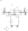
- the robot 11 includes a carriage 12, a pair of robot arms 13, 13 (hereinafter may be simply referred to as "arms") supported by the carriage 12, and a control device 14 housed in the carriage 12.
- Each arm 13 is a horizontally articulated robot arm, and includes an arm portion 15, a wrist portion 17, and a hand portion 18, 19.
- the arm portion 15 functions as a conveyance portion for conveying an electronic component onto the substrate and a swinging portion for swinging the electronic component.
- the arm portion 15 is configured of a first link 15a and a second link 15b.
- the left and right arms 13, 13 have substantially identical structures except the hand portions 18, 19, and the right and left hand portions 18, 19 may have identical configurations or different configurations.
- the left and right arms 13, 13 can operate independently and can operate in association with each other.
- the first link 15a of the arm portion 15 is connected to a base shaft 16 fixed to the upper surface of the carriage 12 by a rotary joint and is turnable around a rotary axis line L1 passing through the axis of the base shaft 16.
- the second link 15b is connected to a front end of the first link 15a by a rotary joint and is turnable around a rotary axis line L2 defined at the front end of the first link 15a.
- the wrist portion 17 is connected to a front end of the second link 15b by a prismatic joint and can move up and down with respect to the second link 15b.
- Each of the hand portions 18, 19 is connected to the wrist portion 17 by a rotary joint and is turnable around a rotary axis line.
- Each arm 13 having the above configuration has joint axes J1 to J4 corresponding to the respective joints.
- a servomotor for driving (not illustrated)
- an encoder (not illustrated) for detecting the rotation angle of the servomotor, and the like are provided so as to correspond to each of the joint axes J1 to J4.
- the rotary axis lines L1 of the first links 15a, 15a of the two arms 13, 13 are on an identical straight line, and the first link 15a of one arm 13 and the first link 15a of the other arm 13 are disposed with a difference in height therebetween in the upward and downward direction.
- the right hand portion 18 is configured of, for example, a transfer portion for transferring the substrate.
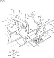
- the left hand portion 19 has a gripping portion 20 for gripping an electronic component 30, and may further have a rotary portion 21 for rotationally moving the gripping portion 20 in the upward and downward direction. Note that although only the left hand portion 19 has the gripping portion 20, it suffices that at least one of the right hand portion 18 and the left hand portion 19 has the gripping portion 20. In a case where both the right hand portion 18 and the left hand portion 19 have the gripping portions 20, the shapes of the gripping portions 20 may differ from each other.
- the rotary portion 21 is an equilateral triangular plate body with three corners cut off.
- the center axis of the rotary portion 21 extends in the direction orthogonal to the joint axis J4 of the wrist portion 17.
- a rotary shaft is provided with a servomotor for driving (not illustrated), an encoder (not illustrated) for detecting the rotation angle of the servomotor, and the like.
- the rotary portion 21 rotates clockwise or counterclockwise about the center axis and stops every time any one of the three sides becomes horizontal.
- six gripping portions 20 are provided in the rotary portion 21. These gripping portions 20 may have identical shapes or may be different according to the shape of the electronic component 30. Two gripping portions 20 are disposed on each side of the rotary portion 21 adjacent to each other with a gap therebetween.
- the gripping portion 20 has a box shape whose lower surface is opened, and has an internal space. Therefore, the inner surfaces of the gripping portion 20 are configured of an upper-side surface, a front-side surface, a rear-side surface, a right-side surface, and a left-side surface.
- the front-side surface, the rear-side surface, the right-side surface, and the left-side surface are parallel to the upward and downward direction and are provided so as to be vertical to the upper-side surface.
- the front-side surface and the rear-side surface are a pair of surfaces facing each other, and the right-side surface and the left-side surface are another pair of surfaces facing each other.
- the pair of surfaces configured of the front-side surface and the rear-side surface are orthogonal to the other pair of surfaces configured of the right-side surface and the left-side surface.
- the gripping portion 20 is opened in a direction away from the center of the rotary portion 21. As a result, when the gripping portion 20 is rotated by the rotary portion 21 and the gripping portion 20 is positioned at the bottom, an opening faces downward. Two adjacent gripping portions 20 are attached to the rotary portion 21 so that the lower surfaces thereof are on a straight line.
- the inner surfaces of the gripping portion 20 are formed so that the internal space of the gripping portion 20 is larger than the electronic component 30.
- a suction device is provided in the internal space of the gripping portion 20.
- a through hole 20h ( Fig. 4A ) is provided in an upper-side wall portion of the gripping portion 20, and a suction pad 22 ( Fig. 4A ) is provided on the inner surface of the upper-side wall portion (upper-side surface) so as to surround the through hole 20h.
- a suctioning pump 23 is provided on the carriage 12 or the like, and the through hole 20h and the suctioning pump 23 are connected through a pipe (not illustrated).
- An on-off valve (not illustrated) is provided in the pipe.
- the control device 14 includes an operation unit 14a such as a CPU, a storage unit 14b such as a ROM and a RAM, and a servo control unit 14c.
- the control device 14 is a robot controller including a computer such as a microcontroller. Note that the control device 14 may be configured of a single control device 14 that performs centralized control, or may be configured of a plurality of control devices 14 that cooperates with each other and performs decentralized control.
- the storage unit 14b stores information such as a basic program as a robot controller, various pieces of fixed data, and the like.
- the operation unit 14a reads and executes software such as the basic program stored in the storage unit 14b to control various operations of the robot 11. That is, the operation unit 14a generates a control command of the robot 11 and outputs the control command to the servo control unit 14c.
- the servo control unit 14c is configured to control driving of the servomotors corresponding to the joint axes J1 to J4 of each arm 13 of the robot 11 according to the control command generated by the operation unit 14a.
- a work table 32 on which the electronic component 30 is disposed and a belt conveyor 33 to which the substrate 40 is transferred are provided in front of the robot 11, a work table 32 on which the electronic component 30 is disposed and a belt conveyor 33 to which the substrate 40 is transferred are provided.
- the electronic component 30 on the work table 32 is disposed with a lead wire 31 facing downward.
- the belt conveyor 33 extends in the rightward and leftward direction, and two substrates 40 disposed side by side in the forward and rearward direction are carried from the left to the right by the belt conveyor 33.
- the robot 11 abuts the left hand portion 19 against the left end of the substrate 40 to move the substrate to the right, and places the substrate 40 on a placement portion 24 positioned in the belt conveyor 33.
- the placement portion 24 is slightly higher than the belt conveyor 33, and the substrate 40 placed on the placement portion 24 stops in front of the robot 11.
- the robot 11 moves the left arm portion 15 forward and moves the gripping portion 20 to the work table 32.
- the suctioning pump 23 is operated to open an on-off valve of the gripping portion 20 positioned at the bottom.
- the electronic component 30 on the work table 32 is suctioned into the gripping portion 20.
- the internal space of the gripping portion 20 is larger than the electronic component 30, when the electronic component 30 is fitted in the internal space of the gripping portion 20, there is a gap between the inner surfaces of the gripping portion 20 and the outer surfaces of the electronic component 30.
- the electronic component 30 is smoothly inserted into the internal space of the gripping portion 20, the upper surface of the electronic component 30 is sucked to the suction pad 22, and the electronic component 30 is gripped by the gripping portion 20.
- the rotary portion 21 is rotated so that another gripping portion 20 faces downward. Then, similarly, the on-off valve of the gripping portion 20 positioned at the bottom is opened, and the gripping portion 20 sucks and grips the electronic component 30. This is repeated for the desired number of times.
- the robot 11 moves the left arm portion 15 rearward and moves the gripping portion 20 and the electronic component 30 gripped by the gripping portion 20 onto the substrate 40.
- the left hand portion 19 is rotated about the joint axis J4 so that the two adjacent gripping portions 20 are arranged side by side in the forward and rearward direction.
- the electronic components 30 can be attached to the substrates 40 arranged in the forward and rearward direction simultaneously or continuously.
- the robot 11 closes the on-off valve of the gripping portion 20 positioned at the bottom.
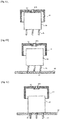
- suctioning (gripping) by the gripping portion 20 is released, and the electronic component 30 is disposed on the substrate 40 from the internal space of the gripping portion 20 and stands by itself.
- the lead wire 31 of the electronic component 30 is inclined, even if the lead wire 31 is positioned above the insertion hole 41 of the substrate 40, the lead wire 31 does not pass through the insertion hole 41, and the lead wire 31 is placed on the substrate 40 and stands by itself.
- the gripping portion 20 is positioned so that the height of the upper surface of the electronic component 30 is higher than the height of the lower end of the gripping portion 20.
- the upper portion of the electronic component 30 is still fitted in the internal space of the gripping portion 20, and is surrounded by the four inner surfaces of the gripping portion 20 with a gap therebetween. Therefore, when the left arm portion 15 repeatedly moves and swings the gripping portion 20 right and left and back and forth, the electronic component 30 is pushed by the respective inner surfaces and moves right and left and back and forth on the substrate 40. As a result, as illustrated in Fig.
- the right hand portion 18 is abutted against the left end of the substrate 40 to move the substrate to the right.
- the substrate 40 is moved from the placement portion 24 to the belt conveyor 33, and the substrate 40 is conveyed by the belt conveyor 33.
- the electronic component 30 is swung.
- the tip of the lead wire 31 matches the insertion hole 41 of the substrate 40, the lead wire 31 can be inserted into the insertion hole 41 due to the own weight of the electronic component 30.
- the gripping portion 20 has a pair of surfaces (the front-side surface and the rear-side surface) which are parallel to the direction in which the lead wire 31 extend and which faces each other, and the other pair of surfaces (the right-side surface and the left-side surface) which are orthogonal to the pair of surfaces.
- a gap is provided between these surfaces and the outer surfaces of the electronic component 30.
- an electronic-component mounting device 10 further includes a position sensor 25 which detects the height of an electronic component 30.
- the position sensor 25 is a distance measuring sensor and is disposed near a suctioning pad in the internal space of the gripping portion 20.
- the position sensor 25 detects the distance to the electronic component 30 which is swung and outputs a detection signal to a control device 14 of a robot 11.
- the gripping portion 20 When the gripping portion 20 is swung, the gripping portion 20 is disposed at a predetermined height from the substrate 40. Therefore, from the difference between the predetermined height of the gripping portion 20 from the substrate 40 and the height from the gripping portion 20 to the electronic component 30 detected by the position sensor 25, the height of the electronic component 30 with respect to the substrate 40 can be detected. In addition, the height of the electronic component 30 from the substrate 40 when a lead wire 31 is inserted into an insertion hole 41 of the substrate 40 is previously obtained. A threshold is set according to this height.
- the position of the electronic component 30 is detected by the position sensor 25. If the height of the electronic component 30 with respect to the substrate 40 obtained from this detection result is larger than the threshold, it is determined that the lead wire 31 is not inserted into the insertion hole 41. As a result, by further swinging the gripping portion 20, the lead wire 31 can be further reliably inserted into the insertion hole 41. In contrast, if the height of the electronic component 30 with respect to the substrate 40 is equal to or less than the threshold, it is determined that the lead wire 31 is inserted into the insertion hole 41. As a result, swinging of the gripping portion 20 is stopped.
- the arm portion 15 is the swinging portion, and the left arm portion 15 swings the electronic component 30 by the gripping portion 20.
- the swinging portion may be any as long as the swinging portion relatively swings the electronic component 30 and the substrate 40.
- a swinging portion (not illustrated) swings a placement portion 24.
- the swinging portion is provided on the placement portion 24, and repeatedly moves a substrate 40 back and forth and right and left with respect to an electronic component 30.
- the gripping portion 20 having a box shape with the lower surface opened and provided with the suction device is used; however, the shape and the gripping method of the gripping portion 20 is not limited to this.
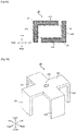
- a gripping portion 28 configured of a first member 26 and a second member 27 may be adopted.
- the first member 26 of the gripping portion 28 is formed in an L shape in a plane orthogonal to the upward and downward direction and has a front-side wall portion 26a extending rightward from a corner and a left-side wall portion 26b extending rearward from the corner.
- the second member 27 is formed in an L shape in the plane orthogonal to the upward and downward direction and has a rear-side wall portion 27a extending leftward from a corner and a right-side wall portion 27b extending forward from the corner.
- the first member 26 and the second member 27 are disposed so that the inner surface of the front-side wall portion 26a (front-side surface) and the inner surface of the rear-side wall portion 27a (rear-side surface) face each other and are parallel to each other, and the inner surface of the left-side wall portion 26b (left-side surface) and the inner surface of the right-side wall portion 27b (right-side surface) face each other and are parallel to each other. Both the first member 26 and the second member 27 are movable in the forward and rearward direction and the rightward and leftward direction.
- the electronic component 30 is sandwiched between the front-side wall portion 26a and the rear-side wall portion 27a in the forward and rearward direction so that the front-side surface is in contact with the front surface of the electronic component 30 and the rear-side surface is in contact with the rear surface of the electronic component 30.
- the electronic component 30 is sandwiched between the left-side wall portion 26b and the right-side wall portion 27b in the rightward and leftward direction so that the left-side surface is in contact with the left surface of the electronic component 30 and the right-side surface is in contact with the right surface of the electronic component 30.
- the gripping portion 28 can grip the electronic component 30.
- the front-side wall portion 26a and the rear-side wall portion 27a are separated from each other in the forward and rearward direction so that the gap between the front-side surface and the rear-side surface is increased, and the left-side wall portion 26b and the right-side wall portion 27b are separated from each other in the rightward and leftward direction so that the gap between the left-side surface and the right-side surface is increased.
- gripping of the electronic component 30 by the gripping portion 28 is released.
- a gap is provided between the outer surfaces of the electronic component 30 and the front-side surface, the rear-side surface, the left-side surface, and the right-side surface of the gripping portion 28.
- a gripping portion 29 illustrated in Fig. 6B may be used.
- This gripping portion 29 has a cross-shaped upper-side wall portion 29a, and a front-side wall portion 29b, a rear-side wall portion 29c, a left-side wall portion 29d and a right-side wall portion 29e which each have a rectangular shape.
- the front-side wall portion 29b extends downward from the front end of the upper-side wall portion 29a
- the rear-side wall portion 29c extends downward from the rear end of the upper-side wall portion 29a
- the left-side wall portion 29d extends downward from the left end of the upper-side wall portion 29a
- the right-side wall portion 29e extends downward from the right end of the upper-side wall portion 29a.
- An internal space of the gripping portion 29 is formed so that a gap is provided between the outer surfaces of the electronic component 30 and the front-side surface, the rear-side surface, the left-side surface, and the right-side surface of the gripping portion 29.
- a through hole 29h is provided at the center of the upper-side surface, and a suctioning pump 23 ( Fig. 1 ) is connected to the through hole 29h through a pipe.
- a suctioning pump 23 Fig. 1
- the electronic component 30 is gripped by the gripping portion 29.
- gripping of the electronic component 30 by the gripping portion 29 is released.
- the electronic component 30 is provided with the three lead wires 31; however, the number of lead wires 31 is not limited thereto, and may be one or more.
- the present invention is useful for an electronic-component mounting device, a method for mounting an electronic component, and the like which can more easily and reliably insert a lead wire into an insertion hole of an electronic circuit substrate.
Landscapes
- Engineering & Computer Science (AREA)
- Manufacturing & Machinery (AREA)
- Microelectronics & Electronic Packaging (AREA)
- Operations Research (AREA)
- Mechanical Engineering (AREA)
- Supply And Installment Of Electrical Components (AREA)
- Manipulator (AREA)
Applications Claiming Priority (2)
| Application Number | Priority Date | Filing Date | Title |
|---|---|---|---|
| JP2016048099A JP6738621B2 (ja) | 2016-03-11 | 2016-03-11 | 電子部品実装装置および電子部品の実装方法 |
| PCT/JP2017/009722 WO2017155094A1 (ja) | 2016-03-11 | 2017-03-10 | 電子部品実装装置および電子部品の実装方法 |
Publications (2)
| Publication Number | Publication Date |
|---|---|
| EP3429328A1 true EP3429328A1 (de) | 2019-01-16 |
| EP3429328A4 EP3429328A4 (de) | 2019-10-30 |
Family
ID=59790429
Family Applications (1)
| Application Number | Title | Priority Date | Filing Date |
|---|---|---|---|
| EP17763426.8A Withdrawn EP3429328A4 (de) | 2016-03-11 | 2017-03-10 | Montagevorrichtung für elektronische komponenten und verfahren zur montage von elektronischen komponenten |
Country Status (7)
| Country | Link |
|---|---|
| US (1) | US20190373781A1 (de) |
| EP (1) | EP3429328A4 (de) |
| JP (1) | JP6738621B2 (de) |
| KR (1) | KR20180118779A (de) |
| CN (1) | CN108781528B (de) |
| TW (1) | TWI647982B (de) |
| WO (1) | WO2017155094A1 (de) |
Families Citing this family (6)
| Publication number | Priority date | Publication date | Assignee | Title |
|---|---|---|---|---|
| JP7278706B2 (ja) * | 2017-11-27 | 2023-05-22 | 川崎重工業株式会社 | 把持装置及び実装装置 |
| JP7306797B2 (ja) * | 2018-05-31 | 2023-07-11 | 川崎重工業株式会社 | 電子部品保持装置 |
| JP7116596B2 (ja) * | 2018-05-31 | 2022-08-10 | 川崎重工業株式会社 | リード線挿入装置およびリード線挿入方法 |
| JP2020196075A (ja) * | 2019-05-31 | 2020-12-10 | 川崎重工業株式会社 | 保持装置、それを備えるロボット、及び保持装置の制御方法 |
| JP7364371B2 (ja) * | 2019-06-28 | 2023-10-18 | 川崎重工業株式会社 | 基板搬送ロボット及び基板搬送ロボットの制御方法 |
| CN111511184B (zh) * | 2020-05-07 | 2021-05-04 | 龙南县方成科技有限公司 | 一种全自动接着机 |
Family Cites Families (11)
| Publication number | Priority date | Publication date | Assignee | Title |
|---|---|---|---|---|
| JPS5379271A (en) * | 1976-12-22 | 1978-07-13 | Fujitsu Ltd | Method of inserting parts into printed board |
| JPS5734390A (en) * | 1980-08-09 | 1982-02-24 | Matsushita Electric Industrial Co Ltd | Part inserting device |
| US4528747A (en) * | 1982-12-02 | 1985-07-16 | At&T Technologies, Inc. | Method and apparatus for mounting multilead components on a circuit board |
| JPS60148200A (ja) * | 1984-01-13 | 1985-08-05 | 日本電気株式会社 | 部品挿入良否の判定方式 |
| JPS612400A (ja) * | 1984-06-14 | 1986-01-08 | 松下電器産業株式会社 | 電子部品の插入検出方法 |
| JP3200401B2 (ja) * | 1997-09-02 | 2001-08-20 | 富士通テン株式会社 | コネクタ実装装置 |
| JP2981997B2 (ja) * | 1997-10-21 | 1999-11-22 | 一彬 山下 | ピン装填装置、ピン供給装置、ピンかしめ装置、基板離脱装置およびこれらを備えた基板組立装置 |
| WO2007007623A2 (en) * | 2005-07-08 | 2007-01-18 | Matsushita Electric Industrial Co., Ltd. | Electronic component mounting apparatus, height detection method for electronic component, and optical-axis adjustment method for component height detection unit |
| US8136219B2 (en) * | 2005-08-02 | 2012-03-20 | Panasonic Corporation | Electronic component mounter and mounting method |
| JP5294204B2 (ja) * | 2009-04-23 | 2013-09-18 | 株式会社 東京ウエルズ | ワーク挿入機構及びワーク挿入方法 |
| JP2013243200A (ja) * | 2012-05-18 | 2013-12-05 | Denso Corp | 測定装置 |
-
2016
- 2016-03-11 JP JP2016048099A patent/JP6738621B2/ja active Active
-
2017
- 2017-03-10 WO PCT/JP2017/009722 patent/WO2017155094A1/ja not_active Ceased
- 2017-03-10 US US16/084,002 patent/US20190373781A1/en not_active Abandoned
- 2017-03-10 CN CN201780015737.2A patent/CN108781528B/zh active Active
- 2017-03-10 TW TW106108229A patent/TWI647982B/zh active
- 2017-03-10 KR KR1020187028879A patent/KR20180118779A/ko not_active Ceased
- 2017-03-10 EP EP17763426.8A patent/EP3429328A4/de not_active Withdrawn
Also Published As
| Publication number | Publication date |
|---|---|
| US20190373781A1 (en) | 2019-12-05 |
| TWI647982B (zh) | 2019-01-11 |
| JP6738621B2 (ja) | 2020-08-12 |
| CN108781528A (zh) | 2018-11-09 |
| CN108781528B (zh) | 2020-11-20 |
| KR20180118779A (ko) | 2018-10-31 |
| TW201811159A (zh) | 2018-03-16 |
| EP3429328A4 (de) | 2019-10-30 |
| JP2017163076A (ja) | 2017-09-14 |
| WO2017155094A1 (ja) | 2017-09-14 |
Similar Documents
| Publication | Publication Date | Title |
|---|---|---|
| EP3429328A1 (de) | Montagevorrichtung für elektronische komponenten und verfahren zur montage von elektronischen komponenten | |
| TWI700164B (zh) | 機器人控制裝置、機器人及機器人系統 | |
| US11485532B2 (en) | Box packing device | |
| CN104044139B (zh) | 机器人系统以及工件的输送方法 | |
| CN111971151B (zh) | 连接装置和连接方法 | |
| CN110573311B (zh) | 机器人设备和电子设备制造方法 | |
| JP6626411B2 (ja) | 食品の詰め込み装置 | |
| CN104802169A (zh) | 并联连杆机器人、并联连杆机器人用手及并联连杆机器人系统 | |
| TWI720688B (zh) | 機器人系統及連接方法 | |
| CN104365188A (zh) | 机器人系统 | |
| CN105407699A (zh) | 插入头、元件插入装置及元件安装线 | |
| US20200068719A1 (en) | Component mounting device and method of controlling the same | |
| TW202132073A (zh) | 保持裝置、控制方法、控制裝置及機器人系統 | |
| JPWO2019064448A1 (ja) | 部品把持具 | |
| WO2021107130A1 (ja) | 保持装置、制御方法、制御装置及びロボットシステム | |
| EP3476552B1 (de) | Werkstückhaltevorrichtung | |
| US20190350249A1 (en) | Extraction mechanism of sheet-like food and method of extracting the sheet-like food using the mechanism | |
| CN117546622A (zh) | 把持机构 | |
| JP2021171855A (ja) | ロボットシステム | |
| JP2011210960A (ja) | 自動実装及び自動組み立てシステム |
Legal Events
| Date | Code | Title | Description |
|---|---|---|---|
| STAA | Information on the status of an ep patent application or granted ep patent |
Free format text: STATUS: THE INTERNATIONAL PUBLICATION HAS BEEN MADE |
|
| PUAI | Public reference made under article 153(3) epc to a published international application that has entered the european phase |
Free format text: ORIGINAL CODE: 0009012 |
|
| STAA | Information on the status of an ep patent application or granted ep patent |
Free format text: STATUS: REQUEST FOR EXAMINATION WAS MADE |
|
| 17P | Request for examination filed |
Effective date: 20181004 |
|
| AK | Designated contracting states |
Kind code of ref document: A1 Designated state(s): AL AT BE BG CH CY CZ DE DK EE ES FI FR GB GR HR HU IE IS IT LI LT LU LV MC MK MT NL NO PL PT RO RS SE SI SK SM TR |
|
| AX | Request for extension of the european patent |
Extension state: BA ME |
|
| DAV | Request for validation of the european patent (deleted) | ||
| DAX | Request for extension of the european patent (deleted) | ||
| A4 | Supplementary search report drawn up and despatched |
Effective date: 20191002 |
|
| RIC1 | Information provided on ipc code assigned before grant |
Ipc: B23P 19/12 20060101ALI20190926BHEP Ipc: H05K 13/08 20060101ALI20190926BHEP Ipc: H05K 13/04 20060101AFI20190926BHEP |
|
| STAA | Information on the status of an ep patent application or granted ep patent |
Free format text: STATUS: THE APPLICATION HAS BEEN WITHDRAWN |
|
| 18W | Application withdrawn |
Effective date: 20200924 |