EP3428928A1 - Cibles en forme de lamelle pour la génération de rayons x - Google Patents
Cibles en forme de lamelle pour la génération de rayons x Download PDFInfo
- Publication number
- EP3428928A1 EP3428928A1 EP18182591.0A EP18182591A EP3428928A1 EP 3428928 A1 EP3428928 A1 EP 3428928A1 EP 18182591 A EP18182591 A EP 18182591A EP 3428928 A1 EP3428928 A1 EP 3428928A1
- Authority
- EP
- European Patent Office
- Prior art keywords
- lamella
- target
- sample
- ray
- electron beam
- Prior art date
- Legal status (The legal status is an assumption and is not a legal conclusion. Google has not performed a legal analysis and makes no representation as to the accuracy of the status listed.)
- Pending
Links
- SWRWCXHNLLPJDZ-UHFFFAOYSA-N CCCC[NH+](C)[O-] Chemical compound CCCC[NH+](C)[O-] SWRWCXHNLLPJDZ-UHFFFAOYSA-N 0.000 description 1
Images


Classifications
-
- G—PHYSICS
- G01—MEASURING; TESTING
- G01N—INVESTIGATING OR ANALYSING MATERIALS BY DETERMINING THEIR CHEMICAL OR PHYSICAL PROPERTIES
- G01N23/00—Investigating or analysing materials by the use of wave or particle radiation, e.g. X-rays or neutrons, not covered by groups G01N3/00 – G01N17/00, G01N21/00 or G01N22/00
- G01N23/02—Investigating or analysing materials by the use of wave or particle radiation, e.g. X-rays or neutrons, not covered by groups G01N3/00 – G01N17/00, G01N21/00 or G01N22/00 by transmitting the radiation through the material
- G01N23/04—Investigating or analysing materials by the use of wave or particle radiation, e.g. X-rays or neutrons, not covered by groups G01N3/00 – G01N17/00, G01N21/00 or G01N22/00 by transmitting the radiation through the material and forming images of the material
- G01N23/046—Investigating or analysing materials by the use of wave or particle radiation, e.g. X-rays or neutrons, not covered by groups G01N3/00 – G01N17/00, G01N21/00 or G01N22/00 by transmitting the radiation through the material and forming images of the material using tomography, e.g. computed tomography [CT]
-
- G—PHYSICS
- G21—NUCLEAR PHYSICS; NUCLEAR ENGINEERING
- G21K—TECHNIQUES FOR HANDLING PARTICLES OR IONISING RADIATION NOT OTHERWISE PROVIDED FOR; IRRADIATION DEVICES; GAMMA RAY OR X-RAY MICROSCOPES
- G21K7/00—Gamma- or X-ray microscopes
-
- H—ELECTRICITY
- H01—ELECTRIC ELEMENTS
- H01J—ELECTRIC DISCHARGE TUBES OR DISCHARGE LAMPS
- H01J35/00—X-ray tubes
- H01J35/02—Details
- H01J35/04—Electrodes ; Mutual position thereof; Constructional adaptations therefor
- H01J35/08—Anodes; Anti cathodes
-
- G—PHYSICS
- G01—MEASURING; TESTING
- G01N—INVESTIGATING OR ANALYSING MATERIALS BY DETERMINING THEIR CHEMICAL OR PHYSICAL PROPERTIES
- G01N2223/00—Investigating materials by wave or particle radiation
- G01N2223/20—Sources of radiation
- G01N2223/204—Sources of radiation source created from radiated target
-
- G—PHYSICS
- G01—MEASURING; TESTING
- G01N—INVESTIGATING OR ANALYSING MATERIALS BY DETERMINING THEIR CHEMICAL OR PHYSICAL PROPERTIES
- G01N2223/00—Investigating materials by wave or particle radiation
- G01N2223/40—Imaging
- G01N2223/401—Imaging image processing
-
- G—PHYSICS
- G01—MEASURING; TESTING
- G01N—INVESTIGATING OR ANALYSING MATERIALS BY DETERMINING THEIR CHEMICAL OR PHYSICAL PROPERTIES
- G01N2223/00—Investigating materials by wave or particle radiation
- G01N2223/40—Imaging
- G01N2223/419—Imaging computed tomograph
-
- H—ELECTRICITY
- H01—ELECTRIC ELEMENTS
- H01J—ELECTRIC DISCHARGE TUBES OR DISCHARGE LAMPS
- H01J2235/00—X-ray tubes
- H01J2235/08—Targets (anodes) and X-ray converters
- H01J2235/081—Target material
-
- H—ELECTRICITY
- H01—ELECTRIC ELEMENTS
- H01J—ELECTRIC DISCHARGE TUBES OR DISCHARGE LAMPS
- H01J2235/00—X-ray tubes
- H01J2235/08—Targets (anodes) and X-ray converters
- H01J2235/086—Target geometry
Definitions
- the present invention relates to systems for generating x-rays and, in particular, to x-ray targets designed to increase the resolution and/or throughput of x-ray imaging and tomography systems.
- An x-ray tomography system can provide information of the internal structure of a sample without having to destroy or cross-section the sample.
- the X-rays are passed through the sample and detected by an x-ray detector to obtain an absorption image from a cross-section of the sample.
- the x-ray detector acquires a two-dimensional x-ray shadow (absorption-contrast) image.
- the sample and/or x-ray source and detector may be incrementally rotated to enable cross sectional images to be obtained from multiple angles.
- the set of cross-sectional images obtained in this manner can then be mathematically manipulated to reconstruct a 3D image of the sample.
- SEM-based nanotomography system comprises any system using an electron beam impinging on a target to generate x-rays and includes a range of x-ray systems designed for very high resolution 2D x-ray imaging and 3D x-ray tomography. Such systems differ from the more common x-ray systems used for lower-resolutions (e.g., > 1 ⁇ m) in their use of an electron beam produced by a scanning electron microscope (SEM), transmission electron microscope (TEM), or scanning transmission electron microscope (STEM), to generate x-rays from a virtual x-ray source typically smaller than ⁇ 500 nm. As the electrons in the beam impact the target, x-rays are generated.
- SEM scanning electron microscope
- TEM transmission electron microscope
- STEM scanning transmission electron microscope
- STEM scanning transmission electron microscope
- Throughput refers to how fast the system can acquire an image or set of images. While there are many definitions of "resolution,” it typically refers to how close two objects can be and still be distinguished as two distinct objects. Resolution affects how small a feature the system can image.
- Throughput can be increased by increasing the flux of x-rays passed through the sample, which may be achieved by increasing the electron beam current impacting the target. However, the impact of the electron beam with the target can cause excessive heating and even melting of the target, thus electron beam currents may be limited to less than 1-2 ⁇ A for beam energies up to 60 keV. Because the electron beam diameters are in the sub-micron range, extremely high energy densities typically arise within the targets.
- x-ray generating systems use focusing optics to focus the generated x-rays
- other systems do not use focusing optics.
- the resolution of an x-ray tomography system without x-ray focusing optics is determined in large part by the effective ("virtual") size of its x-ray source.
- the effective source size is often determined by the volume within which the beam electrons interact with and come to rest in the target. This interaction volume is largely determined by the density and atomic number of the target material, and the diameter and energy of the electron beam, and is typically tear-drop shaped.
- the design of the x-ray target is a critical determinant of the system performance with respect to resolution, imaging time, and image signal-to-noise ratios, as well as other operational considerations.
- the original targets employed in these systems were "bulk targets” - typically pieces of target material (usually metals such as tungsten, molybdenum, titanium, scandium, vanadium, silver, or other a refractory metal, etc.) which were much larger than the diameter of the electron beam used to induce x-ray emission. Since the great majority of the energy of the electron beam striking the target goes into producing heat (not x-rays), the high cooling efficiency of these types of targets was advantageous in maximizing x-ray fluxes and thus throughputs.
- imaging resolutions were limited by the spreading of the electron beam within the target material, since the electron dissipation volume also corresponds to the virtual source size, and thus resolutions were limited.
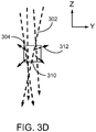
- Post targets comprise very small, approximately rectangular (cross-section), targets having dimensions typically ⁇ 500 nm in the two axes which determine the virtual source size (e.g., Y-Z in FIG. 3D ) and are about 1-2 ⁇ m long (X-dimension), attached to a support base.
- the diameter of the beam spot at the target may be larger than the largest dimension (e.g., diameter of a cylindrical post or diagonal of a rectangular prism post) of a cross section of the post.
- the support base may be composed of a material such as silicon, aluminum, beryllium, or other low atomic number material, which generates fewer x-rays upon impact of the electron beam than the target material.
- An electron beam striking the end of a post target will generate x-rays with a virtual source size controlled by the Y-Z dimensions of the post, rather than the electron dispersion distance as in a bulk target - thus higher imaging resolutions are possible with post targets than with bulk targets.
- thermal conductivity is much lower than for a bulk target, and thus excessive heating presents a limit to the allowable electron beam energy which may be deposited into the target before melting may occur (even for tungsten targets).
- FIGS. 4A-5B address some of these concerns, with FIG. 9 providing a comprehensive summary of the source parameters of the various source types.
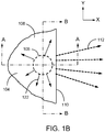
- FIGS. 1A-1D show four views of the operation of an x-ray source employing a bulk target 108 impacted by a round electron beam 106.
- Bulk targets typically comprise a target material, such as tungsten, molybdenum, titanium, scandium, vanadium, silver, or other a refractory metal, etc., which is relatively large in X-Y-Z dimensions compared to the anticipated size of the electron beam which will be directed towards the target to generate x-rays.
- FIG. 1A is an isometric view of a bulk target 108 with an upper surface 104 being bombarded by electrons 102 in an electron beam which has been focused into a round electron beam 106 by an electron column (not shown) such as would be found in a scanning electron microscope (SEM), transmission electron microscope (TEM), scanning transmission electron microscope (STEM), or any electron beam system capable of focusing a high current density electron beam onto a target.
- SEM scanning electron microscope
- TEM transmission electron microscope
- STEM scanning transmission electron microscope
- STEM scanning transmission electron microscope
- STEM scanning transmission electron microscope
- X-ray flux 112 represents only the very small fraction (typically 0.1 to 0.4 %) of the total x-ray flux which is emitted through the front surface 110 of target 108 in a direction towards an x-ray detector (see FIG. 2 ).
- the great majority of the total x-ray flux (not including x-rays 112) generated by impact of electron beam 106 with the bulk target 108 will be emitted in directions away from the x-ray detector and thus will not contribute to x-ray imaging.
- FIG. 1B is a top view (in the X-Y plane) of the x-ray source from FIG. 1A , illustrating two cross-sections A-A and B-B, which are presented in FIGS. 1C and 1D , respectively. Also illustrated is the dissipation of heat 122 generated in target 108 by absorption of kinetic energy from electrons 102. Typically, almost all the electron energy produces heat, with only a small fraction of the electron energy producing x-rays. Because the electron beam 106 is relatively small compared to the dimensions of the bulk target, heat 122 may dissipate out rapidly by thermal conduction over an -180° range (i.e., not through surface 110) in the X-Y plane within target 108 as shown.
- FIG. 1C is a side cross-sectional view A-A (in the X-Z plane) of the x-ray source from FIGS. 1A-1B .
- the penetration distance of electrons 102 into the target 108 is typically a bulb-shaped volume 142 with a depth down from top surface 104 determined by the energy of electrons 102.
- the penetration depth may be microns, while for 1.5 keV electrons the penetration depth may be only ⁇ 50 nm.
- a fraction of the x-rays generated within target 108 may be reabsorbed within target 108 before reaching exit surface 110. In the case of ⁇ 0.5 keV x-rays generated in a titanium target fewer than 20% will typically be absorbed within target 108.
- heat 122 may dissipate out over an -90° range (i.e., not through surfaces 104 or 110) in the X-Z plane from the electron penetration volume 142.
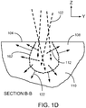
- FIG. 1D is a front cross-sectional view B-B (in the Y-Z plane) of the x-ray source from FIGS. 1A-1B .
- the penetration volume 162 in general will look much like penetration volume 142 in FIG. 1C for cases where the electron beam 102 impacting target 108 is round. As can be seen, heat 122 may dissipate out over an ⁇ 180° angular range in the Y-Z plane from the electron penetration volume 162.
- the wide angular ranges of heat dissipation 122 illustrated in FIGS. 1B-1D show that heat dissipation within a bulk target can be rapid going away from the electron beam (impact region) 106 of the electrons 102 with target 108.
- relatively high electron beam powers may be employed, enabling larger x-ray fluxes to be generated.
- a typical "rule of thumb" for x-ray generation is that x-rays produced by an electron beam will have energies ranging up to about 1/3 of the energy of the electron beam, thus a 30 keV electron beam will efficiently generate x-rays mostly below ⁇ 10 keV, while a higher energy 60 keV electron beam will generate x-rays mostly with energies below ⁇ 20 keV. For some applications, however, much lower x-ray energies may be preferred and will be discussed below.
- a bulk target is thus able to dissipate heat generated in the target from the impact of the electron beam.
- a disadvantage of a bulk target is that the virtual source size is determined by the penetration volume (142 in FIG. 1C and 162 in FIG. 1D ).
- the achievable imaging resolution is fundamentally determined by the source size, thus the larger the source size, the lower the resolution in 2D x-ray images or in 3D x-ray tomographic reconstructions. These issues are discussed further in a subsequent section.
- Table 900 in FIG. 9 summarizes many of the source parameters just discussed.
- the bulk target may be attached to a support structure, which, in turn, may be affixed to a support arm, as illustrated in FIG. 8 .
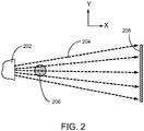
- FIG. 2 shows a top view (in the X-Y plane) projection x-ray imaging arrangement 200.
- X-rays are emitted from a target 202 due to the impact of an electron beam (not shown), as illustrated in FIGS. 1A-1D .
- X-rays generated in target 202 are emitted in all directions (4 ⁇ steradians), however a small fraction (typically 0.1 to 0.4%) 204 of the total x-ray flux is emitted into the solid angle subtended by the x-ray detector 208 with respect to target 202.
- x-ray imaging or x-ray tomography of a sample 206 For x-ray imaging or x-ray tomography of a sample 206, a portion of x-rays 204 will pass through sample 206, with a fraction of the x-rays being absorbed by sample 206, thereby producing a shadow image at detector 208.
- the flow chart in FIG. 10 describes a method for x-ray imaging or x-ray tomography employing an experimental configuration as shown in FIG. 2 .
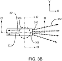
- FIGS. 3A-3D show four views of an x-ray source employing a post target 308 impacted by a round electron beam 306.
- Post targets typically comprise some of the same target materials as bulk targets, such as tungsten, molybdenum, titanium, scandium, vanadium, silver, or a refractory metal, etc. However, unlike the situation for bulk targets, post targets comprise a very small structure elongated along the desired x-ray emission direction (i.e., towards the sample and detector - see FIG. 2 ).
- the virtual source size for a post target is determined by the transverse dimensions (i.e., dimensions along the Y- and Z-axes perpendicular to the X-axis of x-ray emission towards the sample and detector - see FIG. 2 ).
- the transverse dimension in the Y direction may be smaller than the diameter of the electron beam, so that the size of the virtual x-ray source in the Y direction is determined by the Y dimension of the target and not by the diameter of
- Post target 308 is supported on a support structure (not shown) which would be at the upper left of FIG. 3A .
- a support structure (not shown) which would be at the upper left of FIG. 3A .
- the support structure may be fabricated from a material that is less efficient (typically lower atomic number, such as silicon, aluminum or beryllium) at x-ray generation than the material of post target 308, thus even if the edge of electron beam 306 impacts the support structure, minimal extraneous x-ray generation will result which might affect the resolution in the x-ray image.
- the support structure may be fabricated from the same material as post target 308, however, post target 308 would be fabricated with sufficient length (X-axis) to ensure that the electron beam 306 only impacts post target 308 and not the support structure.
- FIG. 3A is an isometric view of a post target 308 with an upper surface 304 being bombarded by electrons 302 in an electron beam which has been focused into a round electron beam 306 by an electron column such as would be found in a scanning electron microscope (SEM), transmission electron microscope (TEM), scanning transmission electron microscope (STEM), or any electron beam system capable of focusing a high current density electron beam onto a target.
- SEM scanning electron microscope
- TEM transmission electron microscope
- STEM scanning transmission electron microscope
- STEM scanning transmission electron microscope
- STEM scanning transmission electron microscope
- STEM scanning transmission electron microscope
- some of electrons 302 may travel out the lower surface of post target 308. Because some electrons 302 may not impact the post target 308 and some other electrons 302 may pass through the post target 308, x-ray generation by post targets may be less efficient (measured in x-ray flux for a given electron beam current) than for a bulk target. As was the case for the bulk target 108 in FIGS. 1A-1D , the impact of electrons 302 with post target 308 generates x-rays which propagate out in all directions (into a 4 ⁇ steradians solid angle). X-ray flux 312 represents the very small fraction (typically 0.1 to 0.4 %) of the total x-ray flux which is emitted through the front surface 310 of target 308 in a direction towards an x-ray detector (see FIG. 2 ).
- FIG. 3B is a top view (in the X-Y plane) of the x-ray source from FIG. 3A , illustrating two cross-sections C-C and D-D, which are presented in FIGS. 3C and 3D , respectively. Also illustrated is the dissipation of heat 322 generated in target 308 by absorption of kinetic energy from electrons 302. Typically, almost all the electron energy produces heat, with only a small fraction of the electron energy producing x-rays, however for a given electron beam current, less heat will be deposited into the post target 308 than would typically be the case for a bulk target 108 due to the two factors discussed above: electrons missing the target, and electrons passing clear through the target. As is shown schematically in FIGS.
- heat dissipated in the post target 308 is not transmitted efficiently away from the impact region of electron beam 306, as illustrated by dissipation arrows 322 where heat may only be conducted down the length of the post target 308 (in the x-direction only), not away in both the X- and Y-directions as was the case for the bulk target 108.
- a post target may absorb somewhat less heat from the electron beam, the temperature rise of the end of post target 308 (at electron beam 306) may be much larger than for a bulk target 108 impacted by the same electron beam current at the same beam voltage.
- FIG. 3C is a side view cross-section C-C (in the X-Z plane) of the post target x-ray source from FIGS. 3A-3B .
- the Z-axis dimension of the post target 308 is smaller than a typical penetration distance of electrons 302, electrons 302 may pass entirely through post target 308, emerging out the bottom as shown.
- x-rays may be emitted from the full Z-axis dimension of post target 308 (region 342), and the Z-axis source size would then correspond to the Z-axis dimension of post target 308.
- the electron beam may stop within a post target 308 having a Z-axis dimension exceeding the penetration depth (i.e., a Z-axis dimension > 50 nm for 1.5 keV electrons).
- a fraction of the x-rays generated within target 308 may be reabsorbed within target 308 before reaching exit surface 310.
- FIG. 3D is a front view cross-section D-D (in the Y-Z plane) of the post target x-ray source from FIGS. 3A-3C .
- the virtual source size will essentially correspond to the surface 310.
- the narrow angular ranges of heat dissipation 322 illustrated in FIGS. 3B-3D show that heat dissipation within a post target may be substantially reduced compared with the bulk target in FIGS. 1A-1D .
- relatively lower electron beam powers may be required relative to bulk targets to avoid target melting, thereby generating lower x-ray fluxes.
- the virtual source size is determined by the Y- and Z-axis dimensions of the post, which may be substantially smaller than the penetration depths 142 and 162 in a bulk target 108 (which determine the source size for the bulk target), higher 2D imaging and 3D tomographic resolutions may be achievable with a post target, although possibly with longer image acquisition times arising from the lower x-ray fluxes produced by post targets.
- the post target may be attached to a support structure, which, in turn, may be affixed to a support arm, as illustrated in FIG. 8 .
- the X-Y-Z dimensions of post target 308 may be determined by the following criteria:
- X-dimension length perpendicular to the electron beam
- X-dimension preferably large enough to prevent the electron beam from impacting the support structure, but also preferably not so long as to make thermal conduction poor from the end (where the electron beam 306 impacts).
- An object of the invention is to provide improved systems that use charged particle beams to produce x-rays for imaging.
- a system for producing an x-ray image of a sample uses a lamella-shaped target to improve the usual tradeoff between imaging resolution and image acquisition time.
- An electron beam is directed along a first axis onto a first surface of a lamella-shaped target.
- the impact of the electrons in the beam onto the lamella-shaped target generates x-rays from within an interaction volume within the lamella-shaped target, and a portion of the x-rays are emitted towards an x-ray detector.
- a sample is positioned along a second axis between the lamella-shaped target and the x-ray detector.
- An x-ray image is acquired by collecting the x-rays which are not absorbed by the sample.
- Lamella-shaped targets provide some of the benefits of both bulk targets and post targets, while avoiding some of the disadvantages of these targets.
- a "lamella-shaped target” as used herein means a target that is shaped like a thin plate, having a height (along the electron beam axis) and a length (along an axis between the target and the detector) that are at least two times the target's width (along a line on the surface of the target facing the detector, the line normal to the electron beam axis).
- Post targets are useful because they provide a small virtual source size, but the small height of the post reduces the thermal conductivity, limiting the electron beam current that can be used.
- Applicant has found that one can limit the virtual source size in the direction along the beam axis by limiting the size of the beam interaction volume, for example, by using relatively low energy photons (e.g., less than 1,000 eV, preferably less than 500 eV, and particularly in the range of between 280 and 530 eV where natural contrast occurs between water and biological materials) or by using a target material having low electron penetration.
- relatively low energy photons e.g., less than 1,000 eV, preferably less than 500 eV, and particularly in the range of between 280 and 530 eV where natural contrast occurs between water and biological materials
- the interaction volume does not extend to the bottom of the lamella-shaped target, then the additional height of the target below the interaction volume will not affect the virtual source size in that direction, but the additional height will provide more target material to carry heat away from the impact point of the beam.
- the interaction volume extends below the surface facing the electron column by an amount less than the height of the lamella-shaped target. In some embodiments, the interaction volume extends less than half of the height of the lamella-shaped target. In some embodiments, the interaction volume extends less than one quarter of the height of the lamella-shaped target.
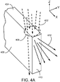
- FIGS. 4A-4D show views of an x-ray source employing a lamella-shaped target 408 with a round electron beam 406.
- An x-ray source with a lamella-shaped target may combine some of the advantages of both the bulk and post targets, while avoiding some of their disadvantages as summarized in table 900 in FIG. 9 .
- Lamella-shaped targets 408 may typically comprise some of the same target materials as bulk targets 108 or post targets 308, including tungsten, molybdenum, titanium, scandium, vanadium, silver, or a refractory metal, etc.
- Lamella-shaped targets 408 present the same narrow Y-axis dimension to the electron beam 406 as a post target, but have a larger Z-axis dimension more characteristic of a bulk target, thereby enabling improved heat conduction and potentially higher x-ray fluxes to be achieved, while still achieving a small virtual source dimension in the Z-axis, especially for low-energy x-ray production.
- FIG. 4A is an isometric view of a lamella-shaped target 408 with an upper surface 404 being bombarded by electrons 402 in an electron beam which has been focused into a round electron beam 406 by an electron column such as would be found in a scanning electron microscope (SEM), transmission electron microscope (TEM), scanning transmission electron microscope (STEM), or any electron beam system capable of focusing a high current density electron beam onto a target.
- SEM scanning electron microscope
- TEM transmission electron microscope
- STEM scanning transmission electron microscope
- STEM scanning transmission electron microscope
- STEM scanning transmission electron microscope
- STEM scanning transmission electron microscope
- the transverse dimension in the Y direction (referred to as the "width" of the lamella-shaped target) may be smaller than the diameter of the electron beam, so that the size of the virtual x-ray source in the Y direction is determined by the Y dimension of the target and not by the diameter of the electron beam.
- Lamella-shaped target 408 is supported on a support structure (not shown) which would be at the upper left of FIG. 4A .
- lamella-shaped target 408 may be partly embedded in the support structure.
- the same at least two approaches (which may be combined in some embodiments) are possible as were described above for the post target 308 in FIGS. 3A-3D .
- lamella-shaped target 408 are cantilevered out from the support structure a distance far enough from the edge of the support structure to reduce or eliminate the amount of electron beam current which strikes the support, instead of striking the lamella-shaped target. This will reduce or eliminate the amount of Bremsstrahlung radiation generated from the support - this radiation tends to reduce the resolution and contrast in the image.
- portions of electron beam 406 may miss the narrow lamella-shaped target 408, travelling past target 408 on either side and thus not producing x-rays.
- the dimension along the Z-axis (referred to as the "height" of the lamella-shaped target) may be larger than the penetration depth, the portion of electron beam 406 which does not miss target 408 completely will subsequently be absorbed by target 408 and will not pass out the bottom as for the post target. Because some electrons 402 may not impact the post target 408, x-ray generation by lamella-shaped targets may be less efficient than for a bulk target (where all electrons strike the target), but more efficient than for a post target (since no electrons pass out the bottom).
- X-ray flux 412 represents the very small fraction of the total x-ray flux which is emitted through the front surface 410 of target 408 in a direction towards an x-ray detector (not shown - see FIG. 2 ).
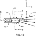
- FIG. 4B is a top view (in the X-Y plane) of the x-ray source from FIG. 4A , illustrating two cross-sections E-E and F-F, which are presented in FIGS. 4C and 4D , respectively. Also illustrated is the dissipation of heat 422 generated in target 408 by absorption of kinetic energy from electrons 402 along the X-direction in the X-Y plane.
- the dimension in the X-direction is referred to as the "length" of the lamella-shaped target. The length has little effect on the virtual source size and so is typically several times as large as the width to aid in the dissipation of heat generated by the electron beam.
- FIG. 4C is a side view cross-section E-E (in the X-Z plane) of the lamella-shaped target x-ray source from FIGS. 4A-4B .
- the Z-axis dimension of the post target 408 is larger than the electron dispersion distance, electrons 402 will stop within the lamella-shaped target.
- the stopping distance may be relatively large (> 1 ⁇ m), resulting a in large Z-dimension for the virtual source size.
- the electron beam may stop within a lamella-shaped target 408.
- a fraction of the x-rays generated within target 408 may be reabsorbed within target 408 before reaching exit surface 410.
- Heat dissipation 422 may propagate out in the Z- and X-directions from the electron penetration volume 442, similarly to the situation in FIG. 1C for the bulk target.
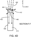
- FIG. 4D is a front view cross-section F-F (in the Y-Z plane) of the lamella-shaped target x-ray source from FIGS. 3A-3C .
- the virtual source region will essentially comprise the upper region of surface 410, arising from electron penetration volume 462. Heat dissipation 422 may flow in the negative Z-direction from electron penetration volume 462.
- the angular ranges of heat dissipation 422 illustrated in FIGS. 4C-4D show that heat dissipation within a lamella-shaped target may be intermediate between the high conduction of the bulk target 108 and the low conduction of the post target 308 - this is summarized in Table 900 in FIG. 9 .
- An additional advantage of a lamella-shaped target in comparison with a post target may be increased mechanical strength, possibly enabling longer target lifetimes and increased reliability.
- the lamella-shaped target may be attached to a support structure, which, in turn, may be affixed to a support arm, as illustrated in FIG. 8 .
- the X-Y-Z dimensions of lamella-shaped target 408 may be determined by the following criteria:
- the X-dimension (length perpendicular to the electron beam) - preferably large enough to prevent the electron beam from impacting the support structure, but also preferably not so long as to make thermal conduction poor from the end (where the electron beam 406 impacts).
- the X-dimension may be at least 500 nm, at least 1 ⁇ m, or at least 2 ⁇ m.
- the Y-dimension (width perpendicular to the electron beam) - comparable to the desired Y-axis resolution in the x-ray image.
- the Y-dimension may be less than 500 nm, less than 250 nm, or less than 100 nm.
- the Z-dimension is preferably larger than the electron penetration depth in the target material.
- the Z-dimension may be at least 200 nm, at least 500 nm, or at least 1 ⁇ m.
- the electron penetration depth is relatively small, and so the additional depth of the lamella-shaped target does not increase the z dimension of the virtual source size.
- the lamella-shaped target therefore reduces heating of the target because it provides additional heat-conductive material to conduct the heat away from the beam impact area and greater surface area to pass the heat into surrounding material or to radiate the heat away.
- the Z dimension and the X dimension are both more than twice the Y dimension.
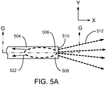
- FIGS. 5A-5B show views of an x-ray source employing a lamella-shaped target with an astigmatic electron beam.
- FIG. 5A is a top view (in the X-Y plane) of a lamella-shaped target 508 (which in some embodiments may be the same as lamella-shaped target 408) with an upper surface 504 being bombarded by electrons 502 in an electron beam which has been focused into an elliptical shape (i.e., astigmatic) 506 by an electron column such as would be found in a scanning electron microscope (SEM), transmission electron microscope (TEM), scanning transmission electron microscope (STEM), or any electron beam system capable of focusing a high current density electron beam onto a target.
- Cross-section G-G is presented in FIG. 5B . Unlike the case for electron beam 406 in FIGS.
- electron beam 506 has been deformed (astigmated) into an elliptical shape 506 so that it entirely falls onto surface 504, thereby increasing the x-ray flux 512 compared flux 412 in FIGS. 4A-4D (since no electrons 502 miss target 508).
- Other aspects of this embodiment may be similar to those for the embodiment in FIGS. 4A-4D .
- Table 900 in FIG. 9 characterizes these aspects further.
- FIG. 5B is a side cross-sectional view G-G (in the X-Z plane) of the x-ray source from FIG. 5A .
- the dissipation of heat 522 generated in target 508 by absorption of kinetic energy from electrons 502 is illustrated, going out from electron dissipation volume 542 in the X- and Z-directions, similarly to the situation in FIG. 4C .
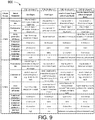
- Table 900 in FIG. 9 summarizes the various aspects of x-ray source operation and performance for bulk targets ( FIGS. 1A-1D ), post targets ( FIGS. 3A-3D ), and lamella-shaped targets used with both round beams ( FIGS. 4A-4D ) and astigmatic (elliptical) electron beams ( FIGS. 5A-5B ). Both high energy (> 5 keV) electron beams and low energy ( ⁇ 2 keV) electron beams are considered.
- the lamella-shaped targets may be most apparent for the low energy beams (lower half of table 900), where the lamella-shaped targets will produce virtual source sizes similar to those of post targets, while enabling generation of higher x-ray fluxes closer to those attainable with bulk targets because of the improved heat dissipation.
- the lamella-shaped targets may still demonstrate some advantages over both bulk and post target x-ray sources in circumstances where an elongated virtual source shape (larger in the Z-direction, smaller in the Y-direction) is acceptable.
- FIG.6 is a graph of x-ray transmission 602 through 100 nm of titanium as a function of the x-ray energy 604 over a broad photon energy range from 280 eV to 520 eV. Below the absorption line 608 near 454 eV the transmission in region 606 ranges up to about 0.86, suddenly dropping to below 0.3 just above the absorption line 608 and then slowly increasing in region 610.
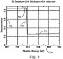
- FIG. 7 is a graph of x-ray transmission 702 through 100 nm of titanium as a function of the x-ray energy 704 over a narrow photon energy range from 450 eV to 460 eV.
- the absorption line 708 at approximately 454 eV, sharply separates the region 706 with transmission above 0.8 from the region 710 with transmission below 0.3.
- Titanium emits x-rays at about 452 eV, which x-rays fall in the low absorption region 706 and so those x-rays are substantially transmitted through the target and onto the target.
- the "water window,” where natural contrast occurs between water and biological materials, corresponds to x-rays in an energy range approximately 280 to 530 eV and so embodiments of the invention are particularly advantageous in imaging biological samples.
- FIG. 8 is a schematic diagram of a SEM-based nano-tomography system 800.
- An electron beam column 802 such as a SEM, TEM, or STEM column in an electron microscope, produces a focused electron beam 804 which may be directed onto an x-ray target 806, which is supported by mounting arm 808 which, in turn, is supported and moved along various axes by target stage 810.
- Target 806 may be a bulk or post target, or may be a lamella-shaped target.
- X-rays 818 are emitted from target 806 towards x-ray detector 820 - a fraction of x-rays 818 may pass through sample (specimen) 814 before reaching detector 820.
- sample 814 may be absorbed by materials within sample 814, resulting in an absorption-contrast image being collected by detector 820.
- Sample 814 is supported, rotated, and positioned by stage 816.
- a vacuum enclosure 812 typically pumped to high vacuum levels, encloses a portion of column 802, target 806, sample 814 and a portion of detector 820.
- electron beam 804 requires a vacuum due to the very small mean free path of electrons in air at atmospheric pressure.
- a system controller 822 is configured to regulate the operation of column 802, target stage 810, sample stage 816, and x-ray detector 820.
- a non-transitory computer-readable storage medium 824 may store computer instructions to system controller 822 to carry out the methods described herein, and may store x-ray image data acquired by detector 820.
- system controller 822 can cause system 800 to acquire multiple x-ray images at different angles through the sample.
- System controller 822 can cause system 800 to form an x-ray image of the sample 814, rotate the sample, form another x-ray image, and repeat this sequence of imaging and rotating multiple times. System controller 822 may then execute a program to reconstruct a three-dimensional representation of the sample from the multiple x-ray images to produce tomographic images.
- a display device 826 may display system control information as well as 2D x-ray images and 3D x-ray tomography results.
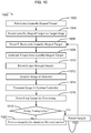
- FIG. 10 is a flow chart 1000 depicting a method for collecting x-ray imaging and tomography data from a sample.
- a lamella-shaped target is fabricated in block 1002.
- target fabrication may be performed using a focused ion beam in a stand-alone microfabrication system such as a dual-beam FIB-SEM produced by Thermo-Fisher Scientific, Corp.
- target fabrication may be performed in a similar system to that shown in FIG. 8 , where an additional focused ion beam column has been added, enabling both FIB-milling of the lamella material as well as SEM imaging for process monitoring and endpoint control. If the lamella is fabricated within the same system as that used for x-ray imaging, then block 1004 may be skipped over (since the lamella-shaped target may already be on the target stage during fabrication).
- the target is mounted on a target stage, as illustrated in the embodiment of FIG. 8 .
- the electron beam column may then be adjusted to focus an electron beam onto the target, typically towards the end of the target nearest the sample and x-ray detector - the beam may be either round (as in FIGS. 4A-4D ) or elliptical (as in FIGS. 5A-5B ).
- x-rays are generated in block 1008 by interactions between the incoming electrons in the beam and inner-shell electrons of the target material in a well-known process. As illustrated in both FIGS.
- stage 816 To proper x-ray imaging, it may be necessary to use stage 816 to position sample 814 within the cone 818 of x-ray flux.
- those x-rays initially emitted from the target 806 towards x-ray detector 820, and not subsequently absorbed within sample 814, will be collected by detector 820 to acquire an x-ray shadow (i.e., absorption) image which is conveyed to system controller 822 in block 1014 and then stored in non-transitory computer-readable storage medium 824 in block 1016.
- x-ray shadow i.e., absorption
- block 1018 if the user is doing 2D x-ray imaging (i.e., not tomography), then block 1020 is entered where the system controller, or another (off-line) processing system, may be employed for image analysis, processing and display. If the user is doing 3D tomography, then a series of images at various rotation angles of sample 814 will typically be required, and block 1022 is entered, wherein the sample is rotated, typically by an angular increment between 0.5° and 2.0°, after which block 1006 is entered and the image acquisition loop comprising blocks 1006-1016 is executed again. This repetition may typically require between 90 and 360 images, after which block 1020 is entered to perform a 3D tomographic reconstruction.
- the methods and apparatus disclosed herein have been described for use in an x-ray tomography system, the methods and apparatus can be generally employed in any type of x-ray projection imaging system. Moreover, in addition to obtaining x-ray absorption images, the disclosed methods and apparatus can be used to obtain other types of sample contrast images, such as phase contrast or diffraction contrast images. Phase and diffraction contrast images may be more useful when imaging samples containing small structures.
Landscapes
- Physics & Mathematics (AREA)
- Engineering & Computer Science (AREA)
- Health & Medical Sciences (AREA)
- General Engineering & Computer Science (AREA)
- High Energy & Nuclear Physics (AREA)
- Theoretical Computer Science (AREA)
- Biochemistry (AREA)
- Radiology & Medical Imaging (AREA)
- Nuclear Medicine, Radiotherapy & Molecular Imaging (AREA)
- Life Sciences & Earth Sciences (AREA)
- Chemical & Material Sciences (AREA)
- Analytical Chemistry (AREA)
- Pulmonology (AREA)
- General Health & Medical Sciences (AREA)
- General Physics & Mathematics (AREA)
- Immunology (AREA)
- Pathology (AREA)
- X-Ray Techniques (AREA)
- Analysing Materials By The Use Of Radiation (AREA)
Applications Claiming Priority (1)
| Application Number | Priority Date | Filing Date | Title |
|---|---|---|---|
| US201762531097P | 2017-07-11 | 2017-07-11 |
Publications (1)
| Publication Number | Publication Date |
|---|---|
| EP3428928A1 true EP3428928A1 (fr) | 2019-01-16 |
Family
ID=62909410
Family Applications (1)
| Application Number | Title | Priority Date | Filing Date |
|---|---|---|---|
| EP18182591.0A Pending EP3428928A1 (fr) | 2017-07-11 | 2018-07-10 | Cibles en forme de lamelle pour la génération de rayons x |
Country Status (4)
| Country | Link |
|---|---|
| US (1) | US10746672B2 (fr) |
| EP (1) | EP3428928A1 (fr) |
| JP (1) | JP7046746B2 (fr) |
| CN (1) | CN109243947B (fr) |
Families Citing this family (16)
| Publication number | Priority date | Publication date | Assignee | Title |
|---|---|---|---|---|
| US20150117599A1 (en) | 2013-10-31 | 2015-04-30 | Sigray, Inc. | X-ray interferometric imaging system |
| US10295485B2 (en) | 2013-12-05 | 2019-05-21 | Sigray, Inc. | X-ray transmission spectrometer system |
| USRE48612E1 (en) | 2013-10-31 | 2021-06-29 | Sigray, Inc. | X-ray interferometric imaging system |
| US10401309B2 (en) | 2014-05-15 | 2019-09-03 | Sigray, Inc. | X-ray techniques using structured illumination |
| US10247683B2 (en) | 2016-12-03 | 2019-04-02 | Sigray, Inc. | Material measurement techniques using multiple X-ray micro-beams |
| JP6937380B2 (ja) | 2017-03-22 | 2021-09-22 | シグレイ、インコーポレイテッド | X線分光を実施するための方法およびx線吸収分光システム |
| US10578566B2 (en) | 2018-04-03 | 2020-03-03 | Sigray, Inc. | X-ray emission spectrometer system |
| US10989822B2 (en) | 2018-06-04 | 2021-04-27 | Sigray, Inc. | Wavelength dispersive x-ray spectrometer |
| GB2591630B (en) | 2018-07-26 | 2023-05-24 | Sigray Inc | High brightness x-ray reflection source |
| US10656105B2 (en) | 2018-08-06 | 2020-05-19 | Sigray, Inc. | Talbot-lau x-ray source and interferometric system |
| US10962491B2 (en) | 2018-09-04 | 2021-03-30 | Sigray, Inc. | System and method for x-ray fluorescence with filtering |
| DE112019004478T5 (de) | 2018-09-07 | 2021-07-08 | Sigray, Inc. | System und verfahren zur röntgenanalyse mit wählbarer tiefe |
| WO2021011209A1 (fr) | 2019-07-15 | 2021-01-21 | Sigray, Inc. | Source de rayons x avec anode tournante à pression atmosphérique |
| WO2021168686A1 (fr) * | 2020-02-26 | 2021-09-02 | Shenzhen Xpectvision Technology Co., Ltd. | Systèmes d'imagerie et leurs procédés d'utilisation |
| CN113764246A (zh) * | 2020-06-03 | 2021-12-07 | 聚束科技(北京)有限公司 | 一种显微镜 |
| CN112213343B (zh) * | 2020-12-03 | 2021-03-16 | 中国科学院自动化研究所 | 塑料条带承载生物超薄切片快速成像方法、系统、装置 |
Citations (5)
| Publication number | Priority date | Publication date | Assignee | Title |
|---|---|---|---|---|
| JPS5515250Y2 (fr) * | 1975-07-29 | 1980-04-08 | ||
| US20080019481A1 (en) * | 2005-03-02 | 2008-01-24 | Jean-Pierre Moy | Monochromatic x-ray source and x-ray microscope using one such source |
| WO2010134282A1 (fr) * | 2009-05-22 | 2010-11-25 | 独立行政法人産業技術総合研究所 | Elément support d'échantillon pour microscopes à rayons x, cellule confinement d'échantillon, microscope à rayons x, et procédé d'observation d'image de microscope à rayons x |
| US20150303021A1 (en) | 2014-04-18 | 2015-10-22 | Fei Company | High aspect ratio x-ray targets and uses of same |
| US20160351370A1 (en) * | 2013-09-19 | 2016-12-01 | Sigray, Inc. | Diverging x-ray sources using linear accumulation |
Family Cites Families (11)
| Publication number | Priority date | Publication date | Assignee | Title |
|---|---|---|---|---|
| US5044001A (en) * | 1987-12-07 | 1991-08-27 | Nanod Ynamics, Inc. | Method and apparatus for investigating materials with X-rays |
| JPH03273200A (ja) * | 1990-03-23 | 1991-12-04 | Elionix Kk | 端部放出型x線顕微鏡 |
| US5148462A (en) * | 1991-04-08 | 1992-09-15 | Moltech Corporation | High efficiency X-ray anode sources |
| AUPQ831200A0 (en) * | 2000-06-22 | 2000-07-13 | X-Ray Technologies Pty Ltd | X-ray micro-target source |
| JP4954526B2 (ja) * | 2005-10-07 | 2012-06-20 | 浜松ホトニクス株式会社 | X線管 |
| DE102005053386A1 (de) * | 2005-11-07 | 2007-05-16 | Comet Gmbh | Nanofocus-Röntgenröhre |
| WO2007141868A1 (fr) * | 2006-06-02 | 2007-12-13 | Hitachi, Ltd. | Microscope à rayons X et méthode de microscopie en rayons X |
| US7336760B2 (en) * | 2006-07-28 | 2008-02-26 | Varian Medical Systems Technologies, Inc. | Methods, systems, and computer-program products to estimate scattered radiation in cone-beam computerized tomographic images and the like |
| US8068579B1 (en) * | 2008-04-09 | 2011-11-29 | Xradia, Inc. | Process for examining mineral samples with X-ray microscope and projection systems |
| US20150092924A1 (en) * | 2013-09-04 | 2015-04-02 | Wenbing Yun | Structured targets for x-ray generation |
| JP6450153B2 (ja) * | 2014-11-07 | 2019-01-09 | 浜松ホトニクス株式会社 | X線像撮像用ユニット、電子顕微鏡及び試料像取得方法 |
-
2018
- 2018-07-10 CN CN201810781507.3A patent/CN109243947B/zh active Active
- 2018-07-10 JP JP2018130470A patent/JP7046746B2/ja active Active
- 2018-07-10 EP EP18182591.0A patent/EP3428928A1/fr active Pending
- 2018-07-11 US US16/032,889 patent/US10746672B2/en active Active
Patent Citations (5)
| Publication number | Priority date | Publication date | Assignee | Title |
|---|---|---|---|---|
| JPS5515250Y2 (fr) * | 1975-07-29 | 1980-04-08 | ||
| US20080019481A1 (en) * | 2005-03-02 | 2008-01-24 | Jean-Pierre Moy | Monochromatic x-ray source and x-ray microscope using one such source |
| WO2010134282A1 (fr) * | 2009-05-22 | 2010-11-25 | 独立行政法人産業技術総合研究所 | Elément support d'échantillon pour microscopes à rayons x, cellule confinement d'échantillon, microscope à rayons x, et procédé d'observation d'image de microscope à rayons x |
| US20160351370A1 (en) * | 2013-09-19 | 2016-12-01 | Sigray, Inc. | Diverging x-ray sources using linear accumulation |
| US20150303021A1 (en) | 2014-04-18 | 2015-10-22 | Fei Company | High aspect ratio x-ray targets and uses of same |
Also Published As
| Publication number | Publication date |
|---|---|
| CN109243947B (zh) | 2023-05-02 |
| JP2019021625A (ja) | 2019-02-07 |
| US20190017942A1 (en) | 2019-01-17 |
| JP7046746B2 (ja) | 2022-04-04 |
| US10746672B2 (en) | 2020-08-18 |
| CN109243947A (zh) | 2019-01-18 |
Similar Documents
| Publication | Publication Date | Title |
|---|---|---|
| US10746672B2 (en) | Lamella-shaped targets for x-ray generation | |
| US8401151B2 (en) | X-ray tube for microsecond X-ray intensity switching | |
| EP3093867B1 (fr) | Générateur de rayons x et son procédé de réglage | |
| Heo et al. | Transmission-type microfocus x-ray tube using carbon nanotube field emitters | |
| CN108369884B (zh) | 电子引导和接收元件 | |
| JP5871528B2 (ja) | 透過型x線発生装置及びそれを用いたx線撮影装置 | |
| US9455120B2 (en) | Particle beam device and method for processing and/or analyzing a sample | |
| US9048064B2 (en) | Cathode assembly for a long throw length X-ray tube | |
| JP2000514238A (ja) | 汎用走査型電子顕微鏡としての電子ビームマイクロカラム | |
| JP2010147017A (ja) | X線管 | |
| Grant et al. | Electron field emission Particle-In-Cell (PIC) coupled with MCNPX simulation of a CNT-based flat-panel x-ray source | |
| JP5458472B2 (ja) | X線管 | |
| Hållstedt et al. | Liquid-metal-jet X-ray technology for nanoelectronics characterization and metrology | |
| JP4029209B2 (ja) | 高分解能x線顕微検査装置 | |
| JP5071949B1 (ja) | ステレオx線発生装置 | |
| JP6695011B1 (ja) | X線発生装置及びx線撮影システム | |
| Vincze et al. | Status and perspectives of capillary optics at a third‐generation synchrotron radiation source | |
| US20140112449A1 (en) | System and method for collimating x-rays in an x-ray tube | |
| WO2015042545A1 (fr) | Lentille magnétique à encoche pour un accès d'échantillon amélioré dans un sem | |
| Yabushita et al. | Development of high spatial resolution x-ray radiography system equipped with multiwalled carbon nanotube field emission cathode | |
| TW202201457A (zh) | 粒子束裝置及複合射束裝置 | |
| WO2010012403A2 (fr) | Cible radiographique et procédé de production de rayons x | |
| KR101023713B1 (ko) | 투과형 또는 반사형 모드의 선택이 가능한 듀얼 x-선 발생장치 | |
| Tuohimaa et al. | High-intensity electron beam for liquid-metal-jet anode hard x-ray generation | |
| EP4220680A1 (fr) | Dispositif à faisceau de particules chargées pour analyse par diffraction |
Legal Events
| Date | Code | Title | Description |
|---|---|---|---|
| PUAI | Public reference made under article 153(3) epc to a published international application that has entered the european phase |
Free format text: ORIGINAL CODE: 0009012 |
|
| STAA | Information on the status of an ep patent application or granted ep patent |
Free format text: STATUS: THE APPLICATION HAS BEEN PUBLISHED |
|
| AK | Designated contracting states |
Kind code of ref document: A1 Designated state(s): AL AT BE BG CH CY CZ DE DK EE ES FI FR GB GR HR HU IE IS IT LI LT LU LV MC MK MT NL NO PL PT RO RS SE SI SK SM TR |
|
| AX | Request for extension of the european patent |
Extension state: BA ME |
|
| STAA | Information on the status of an ep patent application or granted ep patent |
Free format text: STATUS: REQUEST FOR EXAMINATION WAS MADE |
|
| 17P | Request for examination filed |
Effective date: 20190715 |
|
| RBV | Designated contracting states (corrected) |
Designated state(s): AL AT BE BG CH CY CZ DE DK EE ES FI FR GB GR HR HU IE IS IT LI LT LU LV MC MK MT NL NO PL PT RO RS SE SI SK SM TR |
|
| STAA | Information on the status of an ep patent application or granted ep patent |
Free format text: STATUS: EXAMINATION IS IN PROGRESS |
|
| 17Q | First examination report despatched |
Effective date: 20210617 |
|
| STAA | Information on the status of an ep patent application or granted ep patent |
Free format text: STATUS: EXAMINATION IS IN PROGRESS |