EP3428379A1 - Blendrahmen mit aufsatz-rollladenkasten und system zu deren herstellung - Google Patents
Blendrahmen mit aufsatz-rollladenkasten und system zu deren herstellung Download PDFInfo
- Publication number
- EP3428379A1 EP3428379A1 EP18182950.8A EP18182950A EP3428379A1 EP 3428379 A1 EP3428379 A1 EP 3428379A1 EP 18182950 A EP18182950 A EP 18182950A EP 3428379 A1 EP3428379 A1 EP 3428379A1
- Authority
- EP
- European Patent Office
- Prior art keywords
- profile
- frame
- roller shutter
- shutter box
- leg
- Prior art date
- Legal status (The legal status is an assumption and is not a legal conclusion. Google has not performed a legal analysis and makes no representation as to the accuracy of the status listed.)
- Granted
Links
Images
Classifications
-
- E—FIXED CONSTRUCTIONS
- E06—DOORS, WINDOWS, SHUTTERS, OR ROLLER BLINDS IN GENERAL; LADDERS
- E06B—FIXED OR MOVABLE CLOSURES FOR OPENINGS IN BUILDINGS, VEHICLES, FENCES OR LIKE ENCLOSURES IN GENERAL, e.g. DOORS, WINDOWS, BLINDS, GATES
- E06B9/00—Screening or protective devices for wall or similar openings, with or without operating or securing mechanisms; Closures of similar construction
- E06B9/02—Shutters, movable grilles, or other safety closing devices, e.g. against burglary
- E06B9/08—Roll-type closures
- E06B9/11—Roller shutters
- E06B9/17—Parts or details of roller shutters, e.g. suspension devices, shutter boxes, wicket doors, ventilation openings
- E06B9/17007—Shutter boxes; Details or component parts thereof
- E06B9/1703—Fixing of the box; External plastering of the box
-
- E—FIXED CONSTRUCTIONS
- E06—DOORS, WINDOWS, SHUTTERS, OR ROLLER BLINDS IN GENERAL; LADDERS
- E06B—FIXED OR MOVABLE CLOSURES FOR OPENINGS IN BUILDINGS, VEHICLES, FENCES OR LIKE ENCLOSURES IN GENERAL, e.g. DOORS, WINDOWS, BLINDS, GATES
- E06B3/00—Window sashes, door leaves, or like elements for closing wall or like openings; Layout of fixed or moving closures, e.g. windows in wall or like openings; Features of rigidly-mounted outer frames relating to the mounting of wing frames
Definitions
- the invention relates to a window frame with top roller shutter box, comprising an upper frame profile with a steel chamber as part of the frame, the top roller shutter box rests directly or indirectly on the frame profile via a base base profile.
- roller shutter boxes made of plastic profiles, in particular of flat hollow plastic profiles are well known.
- the present invention relates to a top roller shutter box.
- An attachment roller shutter box is likewise known, in which an attachment profile roller shutter box with a base base profile is placed over an adapter profile. Between the bottom base profile and the adapter profile, an additional steel reinforcement is used, which is screwed by means of a screw guided vertically from above possibly with the steel reinforcement of the frame. Also in this design, the additional steel reinforcement including the adapter profile must be mounted prior to assembly of the top roller shutter box, which is problematic in certain applications.
- a comparable construction is also from the DE 94 10 578 U1 known.
- Object of the present invention is therefore to provide a generic system with frame and top roller shutter box available, where necessary, if necessary, subsequently a statically highly effective stiffening of the system can be used without disturbing the usual procedure during assembly and without significantly affecting the thermal insulation.
- the invention solves this object by a window frame with top roller shutter box according to claim 1, preferably in conjunction with one or more of the features of claims 2 to 5, and by a system according to claim 6 and a method according to claim 7.
- the core of the invention is the use of an additional reinforcing profile with a first leg which rests on the upper side of the base base profile, and a second leg, which covers the outer visible surface of the frame profile at least partially when mounted as intended.
- This allows a screw which extends through the second leg of the reinforcing profile according to the invention into the conventional reinforcing profile in the steel chamber of the upper frame profile. This screwing can preferably be done after mounting the attachment roller shutter box on the frame.
- the inventively used, preferably approximately L-shaped reinforcing profile can even be retrofitted by the longer, resting on the bottom base profile legs of the reinforcing profile according to the invention introduced through the outlet slot of the roller shutter in the interior of the roller shutter box and then with the short, the outer viewing surface of the frame profile partially covering leg is bolted to the conventional reinforcing profile in the steel chamber.
- invention or “further” reinforcing profile
- first reinforcing profile
- the longer, resting on the bottom base profile leg of the reinforcing profile according to the invention may, but need not be firmly connected to the ground base profile. If this is desired, the attachment can be done either via a screw and / or for example via a double-sided tape.
- the type of attachment of the longer leg of the reinforcing profile according to the invention on the top of the base base profile depends primarily on the accessibility.
- the reinforcing profile according to the invention is made of steel, in particular as by a coating o. The like.
- the inserted into the steel chamber of the frame profile conventional reinforcing profile may also preferably be made of steel, but it can also other known in the art reinforcing profiles, in particular wholly or partially made of glass fiber reinforced plastic reinforcing profiles are used.
- the inventively provided screwing the reinforcing profile used in the invention with the conventional reinforcing profile in the steel chamber of the upper frame profile - especially as a shear-resistant connection - leads to a stiffening effect, which is far beyond the sum of the stiffening effects of the individual reinforcing profiles used. Since the reinforcing profile used in the invention on the Outer visible surface of the frame or the top of the bottom base profile rests, the inventive reinforcement profile reduces the thermal insulation of the top roller shutter box only to a relatively small extent.
- the screw through the second leg of the reinforcing profile according to the invention and the outer visible surface of the frame profile in the conventional reinforcing profile of the steel chamber of the upper frame profile runs approximately horizontally.
- approximately horizontally is understood a screw that deviates up to 30 °, preferably at most 15 ° from the horizontal.
- a window frame profile which is executed for example by means of a coating
- a paint or an aluminum top shell colored, preferably an additional cover with appropriate surface coating can be used, which covers the second leg of the reinforcing profile according to the invention, which at least partially covers the outer viewing surface of the frame profile completely or partially covers, so that the reinforcing profile used in the invention is no longer visible.
- top roller shutter box and the reinforcing profile according to the invention For mounting the system according to the invention of top roller shutter box and the reinforcing profile according to the invention on a frame preferably the following steps are performed: Manufacture of a top roller shutter box with a base base profile, producing a window frame with a steel frame having upper frame profile with inserted into the steel chamber conventional reinforcing profile, touchdown of the top roller shutter box on the frame, placing or securing the reinforcing profile according to the invention with the first leg on the top of the base base profile, these steps can be performed in any order, and then screwing the second leg of the reinforcing profile according to the invention by the outer visible surface of the frame profile with the inserted into the steel chamber conventional reinforcing profile.
- Fig. 5 is the already mounted, on the top 8 of the frame 4 patch essay roller shutter box 2 with the upper part of the window shown in cross section.
- the top roller shutter box largely corresponds to that from the EP 2 252 759 B1 known attachment roller shutter box of the applicant. In that regard, reference is additionally made to this European patent.
- the essay roller shutter box 2 used according to the invention is usually delivered pre-assembled to the site and placed there on the finished frame 4, wherein a screwing of the base base profile 6 with the upper horizontal frame profile 5 possible, but not necessary.
- the angled cover strip 1 is used to attach the top roller shutter box 2 on the frame 4.
- Fig. 2 the reinforcing profile 18 used according to the invention is shown separately.
- the at the intended installation slightly obliquely extending longer legs 11 is later after mounting on the top 9 of the base base profile 6, while the vertically extending shorter leg 12 of the reinforcing profile 18, the outer visible surface 3 of the upper horizontal frame profile 5 covers approximately half.
- the reinforcing profile 18 used in this embodiment is bent from a flat steel and has prefabricated holes 7 to facilitate the subsequent assembly.
- the reinforcing profile 18 can be placed on the upper side of the frame 4 with the upper side 9 of the base base profile 6 and connected to it, for example by means of a screw connection 16, as shown in FIGS 3 and 4 is shown. If required, additionally or alternatively, the reinforcing profile 18 can be connected to the top side 9 of the base base profile 6 via a double-sided adhesive tape. Such an embodiment is in Fig. 1 shown.
- the small bead between the slightly oblique leg 11 and the vertical leg 12 of the reinforcing profile 18 serves at the same time the direct management of the roller shutter or a running between the roller shutter and the reinforcement profile 18 additional insect screen (not shown in the figures).
- FIG. 4 another embodiment of the invention is shown, in which a reinforcing profile 18 'is provided with slightly larger bead between the two legs 11 and 12, for example, if the outlet slot for the roller shutter is further carried out and no additional insect screen is provided (see also Fig. 5 ).
- This embodiment is used in particular when the outer visible surface 3 of the window frame 4 is colored and the reinforcing profile 18, 18 'is not available in this color.
- the reinforcing profile 18, 18 'according to the invention can be easily mounted on the frame 4 even after mounting the top roller shutter box 2 by the longer leg 11 of the reinforcing profile 18, 18' through the outlet slot for the roller shutter pushed into the roller shutter box interior 10, placed on the top 9 of the base base profile 6, if necessary fixed there by means of double-sided tape there and the short leg 12 is screwed to the reinforcing profile 17 of the frame profile 5.
Landscapes
- Engineering & Computer Science (AREA)
- Structural Engineering (AREA)
- Civil Engineering (AREA)
- Architecture (AREA)
- Operating, Guiding And Securing Of Roll- Type Closing Members (AREA)
Abstract
Description
- Die Erfindung betrifft einen Blendrahmen mit Aufsatz-Rollladenkasten, umfassend ein oberes Blendrahmenprofil mit einer Stahlkammer als Bestandteil des Blendrahmens, wobei der Aufsatz-Rollladenkasten über ein Bodenbasisprofil direkt oder indirekt auf dem Blendrahmenprofil aufliegt.
- Rollladenkästen aus Kunststoffprofilen, insbesondere aus flachen Kunststoffhohlprofilen, sind allgemein bekannt. Man unterscheidet sogenannte Aufsatz-Rollladenkästen, die mit einem Bodenbasisprofil direkt oder über ein Adapterprofil indirekt auf der oberen horizontalen Außenseite eines Blendrahmens montiert werden, und Vorsatzkästen, die in der Regel von außen vor eine Blendrahmenverbreiterung oder eine oberhalb des Blendrahmens angeordnete Blende montiert werden. Die vorliegende Erfindung betrifft einen Aufsatz-Rollladenkasten.
- Aus der
EP 2 252 759 B1 ist ein gattungsgemäßes System mit einem Blendrahmen und Aufsatz-Rollladenkasten bekannt. Üblicherweise ist der Blendrahmen mit Hilfe eines in die sogenannte Stahlkammer eingeschobenen Verstärkungsprofils, üblicherweise einem Stahlprofil, verstärkt, um die Last des aufliegenden Aufsatz-Rollladenkastens abzufangen. Diese Last kann aber bei sehr breiten Aufsatz-Rollladenkästen trotz herkömmlicher Stahlverstärkung im Blendrahmen nicht mehr ausreichend abgetragen werden. - Aus der
DE 699 15 531 T2 ist ein Aufsatz-Rollladenkasten bekannt, bei dem in dem Bodenbasisprofil mehrere flach gefaltete Stahlprofile als Verstärkungen vorgesehen sind. Die Befestigung des Bodenbasisprofils auf dem oberen Blendrahmenholm erfolgt mittels einer senkrecht von oben in die Stahlverstärkung des Blendrahmenprofils geführten Verschraubung. Diese Konstruktion bedingt, dass bei der Montage ein freier Zugang zum Inneren des Rollladenkastens besteht oder dass das Bodenbasisprofil zunächst vor der Montage des eigentlichen Aufsatz-Rollladenkastens mit der Oberseite des Blendrahmens verbunden wird. Bei vormontierten Aufsatz-Rollladenkästen besteht diese Möglichkeit jedoch häufig nicht. - Aus der
EP 2 578 791 A2 ist ebenfalls ein Aufsatz-Rollladenkasten bekannt, bei dem über ein Adapterprofil ein Aufsatz-Rollladenkasten mit einem Bodenbasisprofil aufgesetzt wird. Zwischen dem Bodenbasisprofil und dem Adapterprofil wird eine zusätzliche Stahlverstärkung eingesetzt, die mittels einer senkrecht von oben geführten Schraube ggf. mit der Stahlverstärkung des Blendrahmens verschraubt wird. Auch bei dieser Konstruktion muss die zusätzliche Stahlverstärkung einschließlich des Adapterprofils vor der Montage des Aufsatz-Rollladenkastens montiert werden, was in bestimmten Anwendungsfällen problematisch ist. Eine vergleichbare Konstruktion ist auch aus derDE 94 10 578 U1 bekannt. - Aus der
DE 195 10 203 B4 ist eine Konstruktion für einen Aufsatz-Rollladenkasten bekannt, bei der anstelle eines Kunststoff-Bodenbasisprofils ein Verstärkungsträger aus Metall eingesetzt wird. Derartige Konstruktionen sind allerdings bezüglich ihrer Wärmedämmung nachteilig. - Aus der
DE 33 01 176 C2 wiederum ist eine Konstruktion bekannt, bei der anstelle eines üblichen, eine Stahlkammer aufweisenden Hohlkammerprofils ein zu einem L-förmigen Rumpfprofil beschnittenes Blendrahmenprofil ohne Stahlkammer verwendet wird, auf das von außen ein Z-förmiges Stahlprofil als Versteifung aufgeschraubt wird. Bei dieser Konstruktion entfällt das Bodenbasisprofil des Aufsatz-Rollladenkastens. Die Gesamtkonstruktion ist jedoch außerordentlich aufwendig. - Aufgabe der vorliegenden Erfindung ist es daher, ein gattungsgemäßes System mit Blendrahmen und Aufsatz-Rollladenkasten zur Verfügung zu stellen, bei dem bei Bedarf ggf. auch nachträglich eine statisch hochwirksame Versteifung des Systems eingesetzt werden kann, ohne den üblichen Ablauf bei der Montage zu stören und ohne die Wärmedämmung erheblich zu beeinträchtigen.
- Die Erfindung löst diese Aufgabe durch einen Blendrahmen mit Aufsatz-Rollladenkasten nach Anspruch 1, bevorzugt in Verbindung mit einem oder mehreren der Merkmale der Ansprüche 2 bis 5, sowie durch ein System nach Anspruch 6 bzw. ein Verfahren nach Anspruch 7.
- Kern der Erfindung ist die Verwendung eines zusätzlichen Verstärkungsprofils mit einem ersten Schenkel, der auf der Oberseite des Bodenbasisprofils aufliegt, und einem zweiten Schenkel, der bei bestimmungsgemäßer Montage die Außensichtfläche des Blendrahmenprofils wenigstens teilweise überdeckt. Dieses ermöglicht eine Verschraubung, die durch den zweiten Schenkel des erfindungsgemäßen Verstärkungsprofils bis in das herkömmliche Verstärkungsprofil in der Stahlkammer des oberen Blendrahmenprofils reicht. Diese Verschraubung kann bevorzugt nach Montage des Aufsatz-Rollladenkastens auf dem Blendrahmen erfolgen. Bei Bedarf kann das erfindungsgemäß eingesetzte, bevorzugt etwa L-förmige Verstärkungsprofil sogar noch nachträglich montiert werden, indem der längere, auf dem Bodenbasisprofil aufliegende Schenkel des erfindungsgemäßen Verstärkungsprofils durch den Auslassschlitz des Rollladenpanzers in das Innere des Rollladenkastens eingeführt und anschließend mit dem kurzen, die Außensichtfläche des Blendrahmenprofils teilweise überdeckenden Schenkels mit dem herkömmlichen Verstärkungsprofil in der Stahlkammer verschraubt wird.
- Soweit in dieser Beschreibung der Begriff "erfindungsgemäßes" oder "weiteres" Verstärkungsprofil verwendet wird, ist damit das bei bestimmungsgemäßer Montage mit einem seiner Schenkel auf der Oberseite des Bodenbasisprofils aufliegende und mit seinem zweiten Schenkel die Außensichtfläche des Blendrahmenprofils wenigstens teilweise überdeckende Verstärkungsprofil gemeint, während das in die Stahlkammer eingeschobene Verstärkungsprofil auch als "herkömmliches" oder "erstes" Verstärkungsprofil bezeichnet wird.
- Der längere, auf dem Bodenbasisprofil aufliegende Schenkel des erfindungsgemäßen Verstärkungsprofils kann, muss aber nicht mit dem Bodenbasisprofil fest verbunden werden. Ist dieses gewünscht, kann die Befestigung entweder über eine Verschraubung und/oder beispielsweise über ein doppelseitiges Klebeband erfolgen. Die Art der Befestigung des längeren Schenkels des erfindungsgemäßen Verstärkungsprofils auf der Oberseite des Bodenbasisprofils hängt in erster Linie von der Zugänglichkeit ab.
- Nach einer bevorzugten Ausführungsform der Erfindung wird das erfindungsgemäße Verstärkungsprofil aus Stahl hergestellt, insbesondere als durch eine Lackierung o. dgl. veredeltes Stahlprofil. Das in die Stahlkammer des Blendrahmenprofils eingeschobene herkömmliche Verstärkungsprofil kann ebenfalls bevorzugt aus Stahl bestehen, es können aber auch andere dem Fachmann bekannte Verstärkungsprofile, insbesondere ganz oder teilweise aus glasfaserverstärktem Kunststoff bestehende Verstärkungsprofile eingesetzt werden.
- Die erfindungsgemäß vorgesehene Verschraubung des erfindungsgemäß eingesetzten Verstärkungsprofils mit dem herkömmlichen Verstärkungsprofil in der Stahlkammer des oberen Blendrahmenprofils - insbesondere als schubfeste Verbindung - führt zu einer Versteifungswirkung, die weit über der Summe der Versteifungswirkungen der einzelnen eingesetzten Verstärkungsprofile liegt. Da das erfindungsgemäß eingesetzte Verstärkungsprofil auf der Außensichtfläche des Blendrahmens bzw. der Oberseite des Bodenbasisprofils aufliegt, verringert das erfindungsgemäße Verstärkungsprofil die Wärmedämmung des Aufsatz-Rollladenkastens nur in verhältnismäßig geringem Maße.
- Besonders bevorzugt verläuft die Verschraubung durch den zweiten Schenkel des erfindungsgemäßen Verstärkungsprofils und die Außensichtfläche des Blendrahmenprofils in das herkömmliche Verstärkungsprofil der Stahlkammer des oberen Blendrahmenprofils etwa waagerecht. Unter "etwa waagerecht" wird eine Verschraubung verstanden, die bis zu 30°, bevorzugt maximal 15° von der Waagerechten abweicht.
- Soweit ein Blendrahmenprofil eingesetzt wird, das beispielsweise mittels einer Folierung, einer Lackierung oder einer Aluminium-Aufsatzschale farbig ausgeführt wird, kann bevorzugt eine zusätzliche Abdeckleiste mit entsprechender Oberflächenbeschichtung eingesetzt werden, die den zweiten Schenkel des erfindungsgemäßen Verstärkungsprofils, der die Außensichtfläche des Blendrahmenprofils wenigstens teilweise überdeckt, ganz oder teilweise abdeckt, so dass das erfindungsgemäß eingesetzte Verstärkungsprofil nicht mehr sichtbar ist.
- Zum Montieren des erfindungsgemäßen Systems aus Aufsatz-Rollladenkasten und dem erfindungsgemäßen Verstärkungsprofils auf einem Blendrahmen werden bevorzugt folgende Verfahrensschritte durchgeführt: Herstellen eines Aufsatz-Rollladenkastens mit einem Bodenbasisprofils, Herstellen eines Blendrahmens mit einem eine Stahlkammer aufweisenden oberen Blendrahmenprofil mit in die Stahlkammer eingeschobenem herkömmlichen Verstärkungsprofil, Aufsetzen des Aufsatz-Rollladenkastens auf den Blendrahmen, Auflegen bzw. Befestigen des erfindungsgemäßen Verstärkungsprofils mit dem ersten Schenkel auf die Oberseite des Bodenbasisprofils, wobei diese Verfahrensschritte in beliebiger Reihenfolge ausgeführt werden können, und anschließendes Verschrauben des zweiten Schenkels des erfindungsgemäßen Verstärkungsprofils durch die Außensichtfläche des Blendrahmenprofils mit dem in die Stahlkammer eingeschobenen herkömmlichen Verstärkungsprofil.
- Die Erfindung wird nachfolgend anhand eines Ausführungsbeispiels sowie der Zeichnung näher erläutert. Es zeigen dabei:
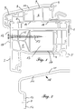
- Fig. 1
- einen Schnitt durch das obere waagerechte Blendrahmenprofil mit aufgesetztem Bodenbasisprofil und erfindungsgemäßem Verstärkungsprofil,
- Fig. 2
- das erfindungsgemäße Verstärkungsprofil,
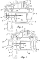
- Fig. 3
- einen Schnitt ähnlich wie
Fig. 1 mit zusätzlicher Abdeckleiste, - Fig. 4
- eine weitere Ausführungsform ähnlich
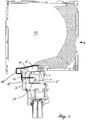
Fig. 3 mit alternativ geformtem Verstärkungsprofil, - Fig. 5
- einen Schnitt durch den oberen Bereich eines Fensters mit aufgesetztem Aufsatz-Rollladenkasten und erfindungsgemäßem Verstärkungsprofil gemäß
Fig. 4 . - In
Fig. 5 ist der bereits montierte, auf die Oberseite 8 des Blendrahmens 4 aufgesetzte Aufsatz-Rollladenkasten 2 mit dem oberen Teil des Fensters im Querschnitt dargestellt. Der Aufsatz-Rollladenkasten entspricht weitestgehend dem aus derEP 2 252 759 B1 bekannten Aufsatz-Rollladenkasten der Anmelderin. Insoweit wird ergänzend auf diese europäische Patentschrift verwiesen. - Der gemäß der Erfindung eingesetzte Aufsatz-Rollladenkasten 2 wird gewöhnlich vormontiert auf die Baustelle geliefert und dort auf den fertigen Blendrahmen 4 aufgesetzt, wobei eine Verschraubung des Bodenbasisprofils 6 mit dem oberen horizontalen Blendrahmenprofil 5 möglich, aber nicht notwendig ist. Auf der Rauminnenseite dient die winkelförmige Abdeckleiste 1 der Befestigung des Aufsatz-Rollladenkastens 2 auf dem Blendrahmen 4.
- In
Fig. 2 ist das erfindungsgemäß eingesetzte Verstärkungsprofil 18 gesondert dargestellt. Der bei bestimmungsgemäßer Montage leicht schräg verlaufende längere Schenkel 11 liegt später nach der Montage auf der Oberseite 9 des Bodenbasisprofils 6 auf, während der vertikal verlaufende kürzere Schenkel 12 des Verstärkungsprofils 18 die Außensichtfläche 3 des oberen horizontalen Blendrahmenprofils 5 etwa zur Hälfte überdeckt. Das in diesem Ausführungsbeispiel eingesetzte Verstärkungsprofil 18 ist aus einem Flachstahl gebogen und weist vorgefertigte Bohrungen 7 zur Erleichterung der späteren Montage auf. - Das Verstärkungsprofil 18 kann bei Bedarf bereits vor der Montage des Aufsatz-Rollladenkastens 2 auf die Oberseite des Blendrahmens 4 mit der Oberseite 9 des Bodenbasisprofils 6 aufgesetzt und mit diesem verbunden werden, beispielsweise durch eine Verschraubung 16, wie sie in den
Fig. 3 und 4 dargestellt ist. Bei Bedarf kann zusätzlich oder alternativ das Verstärkungsprofil 18 über ein doppelseitiges Klebeband mit der Oberseite 9 des Bodenbasisprofils 6 verbunden werden. Eine solche Ausführungsform ist inFig. 1 dargestellt. - Die erfindungswesentliche, etwa horizontale Verschraubung des vertikalen Schenkels 12 des Verstärkungsprofils 18 mit dem in die Stahlkammer 13 des Blendrahmenprofils 5 eingeschobenen herkömmlichen Verstärkungsprofils 17 erfolgt über die Schraube 15. Der durch die Verschraubung 15 erreichte schubfeste Verbund der beiden Verstärkungsprofile 17 und 18 ergibt eine wesentliche Erhöhung des Gesamt-Flächenträgheitsmoments und damit der Steifigkeit der Gesamtkonstruktion, so dass auch hohe Lasten bei sehr breiten Rollladenkästen 2 sicher abgetragen werden können.
- Bei dem in
Fig. 1 dargestellten Ausführungsbeispiel dient der kleine Wulst zwischen dem leicht schräg verlaufenden Schenkel 11 und dem vertikal verlaufenden Schenkel 12 des Verstärkungsprofils 18 zugleich der unmittelbaren Führung des Rollladenpanzers bzw. eines zwischen dem Rollladenpanzer und dem Verstärkungsprofil 18 verlaufenden zusätzlichen Insektenschutzgitters (in den Fig. nicht dargestellt). - In
Fig. 4 ist eine weitere Ausführungsform der Erfindung dargestellt, bei der ein Verstärkungsprofil 18' mit etwas größerem Wulst zwischen den beiden Schenkeln 11 und 12 vorgesehen ist, beispielsweise, wenn der Auslassschlitz für den Rollladenpanzer weiter ausgeführt ist und kein zusätzliches Insektenschutzgitter vorgesehen ist (s. auchFig. 5 ). - In den
Fig. 3 und 4 ist der vertikal verlaufende Schenkel 12 des Verstärkungsprofils 18, 18' mittels einer zusätzlichen Abdeckleiste 20, 20' soweit abgedeckt, dass dieser Schenkel von außen nicht sichtbar ist. Diese Ausführungsform wird insbesondere verwendet, wenn die Außensichtfläche 3 des Blendrahmens 4 farbig ausgestaltet ist und das Verstärkungsprofil 18, 18' nicht in dieser Farbe zur Verfügung steht. - Je nach Zugänglichkeit des Rollladenkasten-Inneren 10 kann das erfindungsgemäße Verstärkungsprofil 18, 18' problemlos auch nach der Montage des Aufsatz-Rollladenkastens 2 auf dem Blendrahmen 4 montiert werden, indem der längere Schenkel 11 des Verstärkungsprofil 18, 18' durch den Auslassschlitz für den Rollladenpanzer in das Rollladenkasten-Innere 10 geschoben, auf die Oberseite 9 des Bodenbasisprofils 6 aufgelegt, ggf. mittels doppelseitigem Klebeband dort fixiert und der kurze Schenkel 12 mit dem Verstärkungsprofil 17 des Blendrahmenprofils 5 verschraubt wird.
-
- 1
- Abdeckleiste
- 2
- Aufsatz-Rollladenkasten
- 3
- Außensichtfläche
- 4
- Blendrahmen
- 5
- Blendrahmenprofil
- 6
- Bodenbasisprofil
- 7
- Bohrung
- 8
- Oberseite (Blendrahmenprofil)
- 9
- Oberseite (Bodenbasisprofil)
- 10
- Rollladenkasten-Inneres
- 11
- Schenkel
- 12
- Schenkel
- 13
- Stahlkammer
- 14
- Unterseite (Bodenbasisprofil)
- 15
- Schraube/Verschraubung (Verstärkungsprofil)
- 16
- Verschraubung (Bodenbasisprofil)
- 17
- erstes Verstärkungsprofil (Blendrahmen)
- 18, 18'
- weiteres Verstärkungsprofil
- 19
- entfällt
- 20, 20'
- Abdeckleiste
Claims (7)
- Blendrahmen (4) mit Aufsatz-Rollladenkasten (2), umfassend- ein oberes Blendrahmenprofil (5) mit einer Stahlkammer (13) als Bestandteil des Blendrahmens (4), wobei das Blendrahmenprofil (5) eine Außensichtfläche (3) aufweist,- ein Bodenbasisprofil (6) als Bestandteil des Aufsatz-Rollladenkastens (2), das direkt oder indirekt auf dem Blendrahmenprofil (5) aufliegt und das eine zum Rollladenkasten-Inneren (10) weisenden Oberseite (9) aufweist,- ein erstes Verstärkungsprofil (17), das in die Stahlkammer (13) des oberen Blendrahmenprofils (5) eingeschoben ist,gekennzeichnet dadurch- ein weiteres Verstärkungsprofil (18, 18') mit einem ersten Schenkel (11), der auf der Oberseite (9) des Bodenbasisprofils (6) aufliegt, und einem zweiten Schenkel (12), der die Außensichtfläche (3) des Blendrahmenprofils (5) wenigsten teilweise überdeckt, und- eine Verschraubung (15), die durch den zweiten Schenkel (12) und die Außensichtfläche (3) des Blendrahmenprofils (5) in das erste Verstärkungsprofil (17) in der Stahlkammer (13) des oberen Blendrahmenprofils (5) geht.
- Blendrahmen (4) mit Aufsatz-Rollladenkasten (2) nach Anspruch 1, dadurch gekennzeichnet, dass auf der Oberseite (9) des Bodenbasisprofils (6) aufliegende weitere Verstärkungsprofil (18, 18') und/oder das das erste Verstärkungsprofil (17) der Stahlkammer (13) aus Stahl gefertigt sind.
- Blendrahmen (4) mit Aufsatz-Rollladenkasten (2) nach Anspruch 1 oder 2, dadurch gekennzeichnet, dass die Verschraubung (15) durch den zweiten Schenkel (12) und die Außensichtfläche (3) des Blendrahmenprofils (5) in das erste Verstärkungsprofil (17) der Stahlkammer (13) des oberen Blendrahmenprofils etwa waagerecht verläuft.
- Blendrahmen (4) mit Aufsatz-Rollladenkasten (2) nach einem der Ansprüche 1 bis 3, gekennzeichnet durch eine weitere Verschraubung (16) durch den ersten Schenkel (11) des auf der Oberseite (9) des Bodenbasisprofils (6) aufliegenden weiteren Verstärkungsprofils (18, 18') in das Bodenbasisprofils (6).
- Blendrahmen (4) mit Aufsatz-Rollladenkasten (2) nach einem der Ansprüche 1 bis 4, gekennzeichnet durch eine zusätzliche Abdeckleiste (20), die den zweiten Schenkel (12) des weiteren Verstärkungsprofils (18, 18') wenigstens teilweise abdeckt.
- System zur Herstellung eines Blendrahmen (4) mit Aufsatz-Rollladenkasten (2), umfassend- ein oberes Blendrahmenprofil (5) zur Herstellung eines Blendrahmens (4) mit einer Stahlkammer (13),- ein Bodenbasisprofil (6) als Bestandteil eines Aufsatz-Rollladenkastens (2),- ein erstes Verstärkungsprofil (17), das in die Stahlkammer (13) des oberen Blendrahmenprofils (5) eingeschoben werden kann,gekennzeichnet dadurch ein weiteres Verstärkungsprofil (18, 18') mit einem ersten Schenkel (11), der auf der Oberseite (9) des Bodenbasisprofils (6) aufgelegt werden kann, und einem zweiten Schenkel (12), der bei bestimmungsgemäßer Verwendung die Außensichtfläche (3) des Blendrahmenprofils (5) wenigsten teilweise überdeckt, umfasst.
- Verfahren zum Montieren eines Aufsatz-Rollladenkastens (2) auf einem Blendrahmen (4) unter Verwendung eines Blendrahmens (4) und Aufsatz-Rollladenkastens (2) nach einem der Ansprüche 1 bis 5, gekennzeichnet durch folgende Verfahrensschritte:a) Herstellen eines Aufsatz-Rollladenkastens (2) mit einem Bodenbasisprofil (6),b) Herstellen eines Blendrahmens (4) mit einem eine Stahlkammer (13) aufweisenden oberen Blendrahmenprofil (5) mit einem in die Stahlkammer (13) eingeschobenem ersten Verstärkungsprofil (17),c) Aufsetzen des Aufsatz-Rollladenkastens (2) auf den Blendrahmen (4),d) Auflegen und ggf. Befestigen des weiteren Verstärkungsprofils (18, 18') mit dem ersten Schenkel (11) auf die Oberseite (9) des Bodenbasisprofils (6),e) anschließendes Verschrauben des zweiten Schenkels (12) des weiteren Verstärkungsprofils (18, 18') durch die Außensichtfläche (3) des Blendrahmenprofils (5) mit dem in die Stahlkammer (13) eingeschobenen ersten Verstärkungsprofil (17),wobei die Verfahrensschritte a) bis d) in beliebiger Reihenfolge ausgeführt werden können.
Applications Claiming Priority (1)
| Application Number | Priority Date | Filing Date | Title |
|---|---|---|---|
| EP17180888.4A EP3428378A1 (de) | 2017-07-12 | 2017-07-12 | Blendrahmen mit aufsatz-rollladenkasten und system zu deren herstellung |
Publications (2)
| Publication Number | Publication Date |
|---|---|
| EP3428379A1 true EP3428379A1 (de) | 2019-01-16 |
| EP3428379B1 EP3428379B1 (de) | 2020-04-22 |
Family
ID=59325192
Family Applications (2)
| Application Number | Title | Priority Date | Filing Date |
|---|---|---|---|
| EP17180888.4A Ceased EP3428378A1 (de) | 2017-07-12 | 2017-07-12 | Blendrahmen mit aufsatz-rollladenkasten und system zu deren herstellung |
| EP18182950.8A Active EP3428379B1 (de) | 2017-07-12 | 2018-07-11 | Blendrahmen mit aufsatz-rollladenkasten und system zu deren herstellung |
Family Applications Before (1)
| Application Number | Title | Priority Date | Filing Date |
|---|---|---|---|
| EP17180888.4A Ceased EP3428378A1 (de) | 2017-07-12 | 2017-07-12 | Blendrahmen mit aufsatz-rollladenkasten und system zu deren herstellung |
Country Status (2)
| Country | Link |
|---|---|
| EP (2) | EP3428378A1 (de) |
| ES (1) | ES2791544T3 (de) |
Citations (7)
| Publication number | Priority date | Publication date | Assignee | Title |
|---|---|---|---|---|
| DE3301176C2 (de) | 1983-01-15 | 1984-10-25 | Ingenieur Klaus Blaurock Bau- und Raumtechnik, 8741 Salz | Stockrahmen für Fenster oder Türen mit aufsetzbarem Rolladenkasten oder dergleichen |
| DE9410578U1 (de) | 1994-06-30 | 1994-09-01 | Rehau Ag + Co, 95111 Rehau | Blendrahmen für Fenster oder Türelemente mit bauseitigem Rolladenkasten |
| DE69915531T2 (de) | 1998-04-23 | 2005-04-07 | Bubendorff Volet Roulant | Rolladenkasten |
| DE19510203B4 (de) | 1994-03-23 | 2009-01-29 | Pax Ag | Fenster- oder Türrahmen, insbesondere für darüber liegenden Rolladenkasteneinbau |
| EP2578791A2 (de) | 2011-10-06 | 2013-04-10 | Veka AG | Rolladenkasten |
| EP2636839A2 (de) * | 2012-03-06 | 2013-09-11 | Exte-Extrudertechnik GmbH | Rollladenkasten und Statikteil |
| EP2252759B1 (de) | 2008-02-05 | 2016-05-18 | profine GmbH | Profilsystem mit einem aufsatz-rollladenkasten mit revisionsklappe |
-
2017
- 2017-07-12 EP EP17180888.4A patent/EP3428378A1/de not_active Ceased
-
2018
- 2018-07-11 ES ES18182950T patent/ES2791544T3/es active Active
- 2018-07-11 EP EP18182950.8A patent/EP3428379B1/de active Active
Patent Citations (7)
| Publication number | Priority date | Publication date | Assignee | Title |
|---|---|---|---|---|
| DE3301176C2 (de) | 1983-01-15 | 1984-10-25 | Ingenieur Klaus Blaurock Bau- und Raumtechnik, 8741 Salz | Stockrahmen für Fenster oder Türen mit aufsetzbarem Rolladenkasten oder dergleichen |
| DE19510203B4 (de) | 1994-03-23 | 2009-01-29 | Pax Ag | Fenster- oder Türrahmen, insbesondere für darüber liegenden Rolladenkasteneinbau |
| DE9410578U1 (de) | 1994-06-30 | 1994-09-01 | Rehau Ag + Co, 95111 Rehau | Blendrahmen für Fenster oder Türelemente mit bauseitigem Rolladenkasten |
| DE69915531T2 (de) | 1998-04-23 | 2005-04-07 | Bubendorff Volet Roulant | Rolladenkasten |
| EP2252759B1 (de) | 2008-02-05 | 2016-05-18 | profine GmbH | Profilsystem mit einem aufsatz-rollladenkasten mit revisionsklappe |
| EP2578791A2 (de) | 2011-10-06 | 2013-04-10 | Veka AG | Rolladenkasten |
| EP2636839A2 (de) * | 2012-03-06 | 2013-09-11 | Exte-Extrudertechnik GmbH | Rollladenkasten und Statikteil |
Also Published As
| Publication number | Publication date |
|---|---|
| EP3428378A1 (de) | 2019-01-16 |
| ES2791544T3 (es) | 2020-11-04 |
| EP3428379B1 (de) | 2020-04-22 |
Similar Documents
| Publication | Publication Date | Title |
|---|---|---|
| DE202012103629U1 (de) | Befestigungsvorrichtung für ein Aussteifungselement eines Rollladenkastens | |
| DE202015102179U1 (de) | Fenstermontagevorrichtung mit Rollladenkasten | |
| EP2796657B1 (de) | Wärmegedämmtes Aussteifungselement für einen Rollladenkasten und Rolladenkasten | |
| AT523544B1 (de) | Kunststoff-Metall-Fenstersystem | |
| DE102013021885A1 (de) | Vorrichtung zur Befestigung eines Fensters oder einer Tür in einer Wandöffnung und Verfahren zum Einbau eines Fensters oder einer Tür in eine Wandöffnung | |
| EP4299870A1 (de) | Blendrahmen für eine tür mit extrusionsrahmen und schwelle, tür mit einem derartigen blendrahmen und verfahren zur herstellung dieser tür | |
| DE102018116805A1 (de) | Blendrahmen mit Aufsatz-Rollladenkasten und System zu deren Herstellung | |
| EP2957698A1 (de) | Montagehilfe für ein Fenster | |
| EP3428379B1 (de) | Blendrahmen mit aufsatz-rollladenkasten und system zu deren herstellung | |
| EP2708693B1 (de) | Schiebeflügelrahmen | |
| EP3293336B1 (de) | Halteschiene für einen französischen balkon sowie haltevorrichtung und anordnung dafür | |
| DE102011051484B4 (de) | Lichtschachtaufstockelement | |
| DE202013011471U1 (de) | Vorrichtung zur Befestigung eines Fensters oder einer Tür in einer Wandöffnung | |
| EP2924227B1 (de) | Mittellagereinheit für wenigstens eine in einem rollladenkasten gelagerte rollladenwelle | |
| EP2530228A2 (de) | Vorrichtung zur statischen Bewehrung von Wandteilen, insbesondere von Glaselementen | |
| EP2439371B1 (de) | Anordnung bestehend aus einer Dichtungsanordnung und einem Schiebefenster oder einer Schiebetür | |
| DE20310086U1 (de) | Torkörper eines Schiebetors | |
| DE9321396U1 (de) | Kunststoff-Hohlprofil | |
| AT506956B1 (de) | Trägersystem für wand- und zusatzelemente | |
| EP4390048A1 (de) | Rahmen für eine schutzvorrichtung | |
| DE102005013978B3 (de) | Tür | |
| DE102023132684A1 (de) | Befestigungsvorrichtung für einen Aufsatzrollladenkasten, Aufsatzrollladenkasten sowie Fenster / Tür mit einem Aufsatzrollladenkasten | |
| DE102021100955A1 (de) | Abdeckeinrichtung für einen Lichtschachtkörper, Anordnung und Verfahren zur Montage einer Abdeckeinrichtung | |
| DE20017167U1 (de) | Vordachanordnung | |
| DE202020006130U1 (de) | Führungsschienenanordnung für eine Pfosten-Riegel-Fassade und mit solchen Führungsschienenanordnungen ausgestattete Pfosten-Riegel-Fassade |
Legal Events
| Date | Code | Title | Description |
|---|---|---|---|
| PUAI | Public reference made under article 153(3) epc to a published international application that has entered the european phase |
Free format text: ORIGINAL CODE: 0009012 |
|
| STAA | Information on the status of an ep patent application or granted ep patent |
Free format text: STATUS: THE APPLICATION HAS BEEN PUBLISHED |
|
| AK | Designated contracting states |
Kind code of ref document: A1 Designated state(s): AL AT BE BG CH CY CZ DE DK EE ES FI FR GB GR HR HU IE IS IT LI LT LU LV MC MK MT NL NO PL PT RO RS SE SI SK SM TR |
|
| AX | Request for extension of the european patent |
Extension state: BA ME |
|
| STAA | Information on the status of an ep patent application or granted ep patent |
Free format text: STATUS: REQUEST FOR EXAMINATION WAS MADE |
|
| 17P | Request for examination filed |
Effective date: 20190716 |
|
| RBV | Designated contracting states (corrected) |
Designated state(s): AL AT BE BG CH CY CZ DE DK EE ES FI FR GB GR HR HU IE IS IT LI LT LU LV MC MK MT NL NO PL PT RO RS SE SI SK SM TR |
|
| RIC1 | Information provided on ipc code assigned before grant |
Ipc: E06B 3/00 20060101ALI20191121BHEP Ipc: E06B 9/17 20060101AFI20191121BHEP |
|
| GRAP | Despatch of communication of intention to grant a patent |
Free format text: ORIGINAL CODE: EPIDOSNIGR1 |
|
| STAA | Information on the status of an ep patent application or granted ep patent |
Free format text: STATUS: GRANT OF PATENT IS INTENDED |
|
| INTG | Intention to grant announced |
Effective date: 20200102 |
|
| GRAS | Grant fee paid |
Free format text: ORIGINAL CODE: EPIDOSNIGR3 |
|
| GRAA | (expected) grant |
Free format text: ORIGINAL CODE: 0009210 |
|
| STAA | Information on the status of an ep patent application or granted ep patent |
Free format text: STATUS: THE PATENT HAS BEEN GRANTED |
|
| AK | Designated contracting states |
Kind code of ref document: B1 Designated state(s): AL AT BE BG CH CY CZ DE DK EE ES FI FR GB GR HR HU IE IS IT LI LT LU LV MC MK MT NL NO PL PT RO RS SE SI SK SM TR |
|
| REG | Reference to a national code |
Ref country code: CH Ref legal event code: EP |
|
| REG | Reference to a national code |
Ref country code: DE Ref legal event code: R096 Ref document number: 502018001252 Country of ref document: DE |
|
| REG | Reference to a national code |
Ref country code: IE Ref legal event code: FG4D Free format text: LANGUAGE OF EP DOCUMENT: GERMAN |
|
| REG | Reference to a national code |
Ref country code: AT Ref legal event code: REF Ref document number: 1260287 Country of ref document: AT Kind code of ref document: T Effective date: 20200515 |
|
| REG | Reference to a national code |
Ref country code: LT Ref legal event code: MG4D |
|
| REG | Reference to a national code |
Ref country code: NL Ref legal event code: MP Effective date: 20200422 |
|
| PG25 | Lapsed in a contracting state [announced via postgrant information from national office to epo] |
Ref country code: SE Free format text: LAPSE BECAUSE OF FAILURE TO SUBMIT A TRANSLATION OF THE DESCRIPTION OR TO PAY THE FEE WITHIN THE PRESCRIBED TIME-LIMIT Effective date: 20200422 Ref country code: NL Free format text: LAPSE BECAUSE OF FAILURE TO SUBMIT A TRANSLATION OF THE DESCRIPTION OR TO PAY THE FEE WITHIN THE PRESCRIBED TIME-LIMIT Effective date: 20200422 Ref country code: FI Free format text: LAPSE BECAUSE OF FAILURE TO SUBMIT A TRANSLATION OF THE DESCRIPTION OR TO PAY THE FEE WITHIN THE PRESCRIBED TIME-LIMIT Effective date: 20200422 Ref country code: IS Free format text: LAPSE BECAUSE OF FAILURE TO SUBMIT A TRANSLATION OF THE DESCRIPTION OR TO PAY THE FEE WITHIN THE PRESCRIBED TIME-LIMIT Effective date: 20200822 Ref country code: GR Free format text: LAPSE BECAUSE OF FAILURE TO SUBMIT A TRANSLATION OF THE DESCRIPTION OR TO PAY THE FEE WITHIN THE PRESCRIBED TIME-LIMIT Effective date: 20200723 Ref country code: NO Free format text: LAPSE BECAUSE OF FAILURE TO SUBMIT A TRANSLATION OF THE DESCRIPTION OR TO PAY THE FEE WITHIN THE PRESCRIBED TIME-LIMIT Effective date: 20200722 Ref country code: PT Free format text: LAPSE BECAUSE OF FAILURE TO SUBMIT A TRANSLATION OF THE DESCRIPTION OR TO PAY THE FEE WITHIN THE PRESCRIBED TIME-LIMIT Effective date: 20200824 Ref country code: LT Free format text: LAPSE BECAUSE OF FAILURE TO SUBMIT A TRANSLATION OF THE DESCRIPTION OR TO PAY THE FEE WITHIN THE PRESCRIBED TIME-LIMIT Effective date: 20200422 |
|
| REG | Reference to a national code |
Ref country code: ES Ref legal event code: FG2A Ref document number: 2791544 Country of ref document: ES Kind code of ref document: T3 Effective date: 20201104 |
|
| PG25 | Lapsed in a contracting state [announced via postgrant information from national office to epo] |
Ref country code: LV Free format text: LAPSE BECAUSE OF FAILURE TO SUBMIT A TRANSLATION OF THE DESCRIPTION OR TO PAY THE FEE WITHIN THE PRESCRIBED TIME-LIMIT Effective date: 20200422 Ref country code: RS Free format text: LAPSE BECAUSE OF FAILURE TO SUBMIT A TRANSLATION OF THE DESCRIPTION OR TO PAY THE FEE WITHIN THE PRESCRIBED TIME-LIMIT Effective date: 20200422 Ref country code: BG Free format text: LAPSE BECAUSE OF FAILURE TO SUBMIT A TRANSLATION OF THE DESCRIPTION OR TO PAY THE FEE WITHIN THE PRESCRIBED TIME-LIMIT Effective date: 20200722 Ref country code: HR Free format text: LAPSE BECAUSE OF FAILURE TO SUBMIT A TRANSLATION OF THE DESCRIPTION OR TO PAY THE FEE WITHIN THE PRESCRIBED TIME-LIMIT Effective date: 20200422 |
|
| PG25 | Lapsed in a contracting state [announced via postgrant information from national office to epo] |
Ref country code: AL Free format text: LAPSE BECAUSE OF FAILURE TO SUBMIT A TRANSLATION OF THE DESCRIPTION OR TO PAY THE FEE WITHIN THE PRESCRIBED TIME-LIMIT Effective date: 20200422 |
|
| REG | Reference to a national code |
Ref country code: DE Ref legal event code: R097 Ref document number: 502018001252 Country of ref document: DE |
|
| PG25 | Lapsed in a contracting state [announced via postgrant information from national office to epo] |
Ref country code: IT Free format text: LAPSE BECAUSE OF FAILURE TO SUBMIT A TRANSLATION OF THE DESCRIPTION OR TO PAY THE FEE WITHIN THE PRESCRIBED TIME-LIMIT Effective date: 20200422 Ref country code: CZ Free format text: LAPSE BECAUSE OF FAILURE TO SUBMIT A TRANSLATION OF THE DESCRIPTION OR TO PAY THE FEE WITHIN THE PRESCRIBED TIME-LIMIT Effective date: 20200422 Ref country code: RO Free format text: LAPSE BECAUSE OF FAILURE TO SUBMIT A TRANSLATION OF THE DESCRIPTION OR TO PAY THE FEE WITHIN THE PRESCRIBED TIME-LIMIT Effective date: 20200422 Ref country code: SM Free format text: LAPSE BECAUSE OF FAILURE TO SUBMIT A TRANSLATION OF THE DESCRIPTION OR TO PAY THE FEE WITHIN THE PRESCRIBED TIME-LIMIT Effective date: 20200422 Ref country code: EE Free format text: LAPSE BECAUSE OF FAILURE TO SUBMIT A TRANSLATION OF THE DESCRIPTION OR TO PAY THE FEE WITHIN THE PRESCRIBED TIME-LIMIT Effective date: 20200422 Ref country code: DK Free format text: LAPSE BECAUSE OF FAILURE TO SUBMIT A TRANSLATION OF THE DESCRIPTION OR TO PAY THE FEE WITHIN THE PRESCRIBED TIME-LIMIT Effective date: 20200422 |
|
| PG25 | Lapsed in a contracting state [announced via postgrant information from national office to epo] |
Ref country code: SK Free format text: LAPSE BECAUSE OF FAILURE TO SUBMIT A TRANSLATION OF THE DESCRIPTION OR TO PAY THE FEE WITHIN THE PRESCRIBED TIME-LIMIT Effective date: 20200422 Ref country code: PL Free format text: LAPSE BECAUSE OF FAILURE TO SUBMIT A TRANSLATION OF THE DESCRIPTION OR TO PAY THE FEE WITHIN THE PRESCRIBED TIME-LIMIT Effective date: 20200422 Ref country code: MC Free format text: LAPSE BECAUSE OF FAILURE TO SUBMIT A TRANSLATION OF THE DESCRIPTION OR TO PAY THE FEE WITHIN THE PRESCRIBED TIME-LIMIT Effective date: 20200422 |
|
| PLBE | No opposition filed within time limit |
Free format text: ORIGINAL CODE: 0009261 |
|
| STAA | Information on the status of an ep patent application or granted ep patent |
Free format text: STATUS: NO OPPOSITION FILED WITHIN TIME LIMIT |
|
| 26N | No opposition filed |
Effective date: 20210125 |
|
| REG | Reference to a national code |
Ref country code: BE Ref legal event code: MM Effective date: 20200731 |
|
| PG25 | Lapsed in a contracting state [announced via postgrant information from national office to epo] |
Ref country code: LU Free format text: LAPSE BECAUSE OF NON-PAYMENT OF DUE FEES Effective date: 20200711 |
|
| PG25 | Lapsed in a contracting state [announced via postgrant information from national office to epo] |
Ref country code: SI Free format text: LAPSE BECAUSE OF FAILURE TO SUBMIT A TRANSLATION OF THE DESCRIPTION OR TO PAY THE FEE WITHIN THE PRESCRIBED TIME-LIMIT Effective date: 20200422 Ref country code: BE Free format text: LAPSE BECAUSE OF NON-PAYMENT OF DUE FEES Effective date: 20200731 |
|
| PG25 | Lapsed in a contracting state [announced via postgrant information from national office to epo] |
Ref country code: IE Free format text: LAPSE BECAUSE OF NON-PAYMENT OF DUE FEES Effective date: 20200711 |
|
| REG | Reference to a national code |
Ref country code: CH Ref legal event code: PL |
|
| PG25 | Lapsed in a contracting state [announced via postgrant information from national office to epo] |
Ref country code: LI Free format text: LAPSE BECAUSE OF NON-PAYMENT OF DUE FEES Effective date: 20210731 Ref country code: CH Free format text: LAPSE BECAUSE OF NON-PAYMENT OF DUE FEES Effective date: 20210731 |
|
| PG25 | Lapsed in a contracting state [announced via postgrant information from national office to epo] |
Ref country code: TR Free format text: LAPSE BECAUSE OF FAILURE TO SUBMIT A TRANSLATION OF THE DESCRIPTION OR TO PAY THE FEE WITHIN THE PRESCRIBED TIME-LIMIT Effective date: 20200422 Ref country code: MT Free format text: LAPSE BECAUSE OF FAILURE TO SUBMIT A TRANSLATION OF THE DESCRIPTION OR TO PAY THE FEE WITHIN THE PRESCRIBED TIME-LIMIT Effective date: 20200422 Ref country code: CY Free format text: LAPSE BECAUSE OF FAILURE TO SUBMIT A TRANSLATION OF THE DESCRIPTION OR TO PAY THE FEE WITHIN THE PRESCRIBED TIME-LIMIT Effective date: 20200422 |
|
| PG25 | Lapsed in a contracting state [announced via postgrant information from national office to epo] |
Ref country code: MK Free format text: LAPSE BECAUSE OF FAILURE TO SUBMIT A TRANSLATION OF THE DESCRIPTION OR TO PAY THE FEE WITHIN THE PRESCRIBED TIME-LIMIT Effective date: 20200422 |
|
| REG | Reference to a national code |
Ref country code: DE Ref legal event code: R081 Ref document number: 502018001252 Country of ref document: DE Owner name: PROFINE GMBH, DE Free format text: FORMER OWNER: PROFINE GMBH, 53840 TROISDORF, DE |
|
| GBPC | Gb: european patent ceased through non-payment of renewal fee |
Effective date: 20220711 |
|
| PG25 | Lapsed in a contracting state [announced via postgrant information from national office to epo] |
Ref country code: GB Free format text: LAPSE BECAUSE OF NON-PAYMENT OF DUE FEES Effective date: 20220711 |
|
| REG | Reference to a national code |
Ref country code: AT Ref legal event code: MM01 Ref document number: 1260287 Country of ref document: AT Kind code of ref document: T Effective date: 20230711 |
|
| PG25 | Lapsed in a contracting state [announced via postgrant information from national office to epo] |
Ref country code: AT Free format text: LAPSE BECAUSE OF NON-PAYMENT OF DUE FEES Effective date: 20230711 |
|
| PG25 | Lapsed in a contracting state [announced via postgrant information from national office to epo] |
Ref country code: AT Free format text: LAPSE BECAUSE OF NON-PAYMENT OF DUE FEES Effective date: 20230711 |
|
| PGFP | Annual fee paid to national office [announced via postgrant information from national office to epo] |
Ref country code: ES Payment date: 20250826 Year of fee payment: 8 |
|
| PGFP | Annual fee paid to national office [announced via postgrant information from national office to epo] |
Ref country code: DE Payment date: 20250722 Year of fee payment: 8 |
|
| PGFP | Annual fee paid to national office [announced via postgrant information from national office to epo] |
Ref country code: FR Payment date: 20250725 Year of fee payment: 8 |
|
| PGFP | Annual fee paid to national office [announced via postgrant information from national office to epo] |
Ref country code: AT Payment date: 20260410 Year of fee payment: 5 |