EP3426142B1 - Elektrodenhaube - Google Patents
Elektrodenhaube Download PDFInfo
- Publication number
- EP3426142B1 EP3426142B1 EP17711072.3A EP17711072A EP3426142B1 EP 3426142 B1 EP3426142 B1 EP 3426142B1 EP 17711072 A EP17711072 A EP 17711072A EP 3426142 B1 EP3426142 B1 EP 3426142B1
- Authority
- EP
- European Patent Office
- Prior art keywords
- electrode
- head
- assembly
- test subject
- reference electrode
- Prior art date
- Legal status (The legal status is an assumption and is not a legal conclusion. Google has not performed a legal analysis and makes no representation as to the accuracy of the status listed.)
- Revoked
Links
Images

Classifications
-
- A—HUMAN NECESSITIES
- A61—MEDICAL OR VETERINARY SCIENCE; HYGIENE
- A61B—DIAGNOSIS; SURGERY; IDENTIFICATION
- A61B5/00—Measuring for diagnostic purposes; Identification of persons
- A61B5/24—Detecting, measuring or recording bioelectric or biomagnetic signals of the body or parts thereof
- A61B5/25—Bioelectric electrodes therefor
- A61B5/279—Bioelectric electrodes therefor specially adapted for particular uses
- A61B5/291—Bioelectric electrodes therefor specially adapted for particular uses for electroencephalography [EEG]
-
- A—HUMAN NECESSITIES
- A61—MEDICAL OR VETERINARY SCIENCE; HYGIENE
- A61B—DIAGNOSIS; SURGERY; IDENTIFICATION
- A61B5/00—Measuring for diagnostic purposes; Identification of persons
- A61B5/05—Detecting, measuring or recording for diagnosis by means of electric currents or magnetic fields; Measuring using microwaves or radio waves
-
- A—HUMAN NECESSITIES
- A61—MEDICAL OR VETERINARY SCIENCE; HYGIENE
- A61B—DIAGNOSIS; SURGERY; IDENTIFICATION
- A61B5/00—Measuring for diagnostic purposes; Identification of persons
- A61B5/24—Detecting, measuring or recording bioelectric or biomagnetic signals of the body or parts thereof
- A61B5/25—Bioelectric electrodes therefor
- A61B5/279—Bioelectric electrodes therefor specially adapted for particular uses
- A61B5/28—Bioelectric electrodes therefor specially adapted for particular uses for electrocardiography [ECG]
- A61B5/282—Holders for multiple electrodes
-
- A—HUMAN NECESSITIES
- A61—MEDICAL OR VETERINARY SCIENCE; HYGIENE
- A61B—DIAGNOSIS; SURGERY; IDENTIFICATION
- A61B5/00—Measuring for diagnostic purposes; Identification of persons
- A61B5/24—Detecting, measuring or recording bioelectric or biomagnetic signals of the body or parts thereof
- A61B5/30—Input circuits therefor
- A61B5/307—Input circuits therefor specially adapted for particular uses
- A61B5/31—Input circuits therefor specially adapted for particular uses for electroencephalography [EEG]
-
- A—HUMAN NECESSITIES
- A61—MEDICAL OR VETERINARY SCIENCE; HYGIENE
- A61B—DIAGNOSIS; SURGERY; IDENTIFICATION
- A61B5/00—Measuring for diagnostic purposes; Identification of persons
- A61B5/68—Arrangements of detecting, measuring or recording means, e.g. sensors, in relation to patient
- A61B5/6801—Arrangements of detecting, measuring or recording means, e.g. sensors, in relation to patient specially adapted to be attached to or worn on the body surface
- A61B5/6802—Sensor mounted on worn items
- A61B5/6803—Head-worn items, e.g. helmets, masks, headphones or goggles
-
- A—HUMAN NECESSITIES
- A61—MEDICAL OR VETERINARY SCIENCE; HYGIENE
- A61B—DIAGNOSIS; SURGERY; IDENTIFICATION
- A61B5/00—Measuring for diagnostic purposes; Identification of persons
- A61B5/68—Arrangements of detecting, measuring or recording means, e.g. sensors, in relation to patient
- A61B5/6801—Arrangements of detecting, measuring or recording means, e.g. sensors, in relation to patient specially adapted to be attached to or worn on the body surface
- A61B5/6813—Specially adapted to be attached to a specific body part
- A61B5/6814—Head
-
- A—HUMAN NECESSITIES
- A61—MEDICAL OR VETERINARY SCIENCE; HYGIENE
- A61B—DIAGNOSIS; SURGERY; IDENTIFICATION
- A61B5/00—Measuring for diagnostic purposes; Identification of persons
- A61B5/68—Arrangements of detecting, measuring or recording means, e.g. sensors, in relation to patient
- A61B5/6801—Arrangements of detecting, measuring or recording means, e.g. sensors, in relation to patient specially adapted to be attached to or worn on the body surface
- A61B5/683—Means for maintaining contact with the body
- A61B5/6831—Straps, bands or harnesses
-
- A—HUMAN NECESSITIES
- A61—MEDICAL OR VETERINARY SCIENCE; HYGIENE
- A61B—DIAGNOSIS; SURGERY; IDENTIFICATION
- A61B2562/00—Details of sensors; Constructional details of sensor housings or probes; Accessories for sensors
- A61B2562/02—Details of sensors specially adapted for in-vivo measurements
- A61B2562/0209—Special features of electrodes classified in A61B5/24, A61B5/25, A61B5/283, A61B5/291, A61B5/296, A61B5/053
-
- A—HUMAN NECESSITIES
- A61—MEDICAL OR VETERINARY SCIENCE; HYGIENE
- A61B—DIAGNOSIS; SURGERY; IDENTIFICATION
- A61B2562/00—Details of sensors; Constructional details of sensor housings or probes; Accessories for sensors
- A61B2562/16—Details of sensor housings or probes; Details of structural supports for sensors
- A61B2562/164—Details of sensor housings or probes; Details of structural supports for sensors the sensor is mounted in or on a conformable substrate or carrier
Definitions
- the invention relates to an electrode hood comprising at least one electrode arrangement for application to the head of a subject according to claim 1.
- the invention further relates to an EEG measurement arrangement according to claim 8.
- the font EP 2 886 049 A1 discloses a garment with an electrode arrangement for measuring biopotentials according to the preamble of claim 1.
- the disadvantage with such electrode hoods is that measurement signals at individual electrodes are subject to different disturbances.
- the object of the invention is to provide an electrode hood which is largely unaffected by interference from electromagnetic fields or structures outside the electrode hood.
- the present invention solves this problem with an electrode hood of the type mentioned at the outset with the features of patent claim 1.
- the continuous conductive body influences the measurement signals of all electrodes equally from the outside of the electrode hood, so that simple compensation can be used to obtain signals which are completely independent of the external electromagnetic influences or disturbances.
- a reference electrode arrangement is provided for application to the subject's head, which has at least one electrode which faces the subject's head and which is electrically conductive with the individual conductive bodies Electrode assemblies is connected.
- the conductive body of the reference electrode arrangement is electrically conductively connected to the conductive bodies of all electrode arrangements.
- a simple way of creating a continuous conductive body provides that the conductive body of the or each electrode arrangement, optionally the reference electrode arrangement, is formed by a fluid, in particular a saline solution, in electrical contact with the reference electrode and / or with the second electrode. and / or that the conductive body has a specific conductivity of between 2 mS / cm and 40mS / cm.
- the individual electrode arrangements and optionally the reference electrode arrangement each have a container delimited by the reference electrode and / or the second electrode, in which the fluid is contained, and that the individual containers are connected to one another, in particular via Hose connections, in communication and form such communicating vessels.
- the electrode hood is designed as a tubular network of electrode arrangements connected to one another via hose connections, the individual containers of the electrode arrangements having connections for, in particular reversible, connection with hose connections.
- a particularly advantageous contacting of the subject's head with the electrode hood provides that at least one or each of the electrode arrangements, and optionally the reference electrode arrangement, has a recess, which is delimited by the measuring electrode or the first electrode and is open towards the subject's head, for receiving conductive gel .
- An advantageous measuring arrangement comprises an electrode hood according to the invention and a measuring device for determining the voltages applied to the electrodes.
- a processing unit is provided which relates those electrical signals which are present at the measuring electrode and the reference electrode to the same electrode arrangement, in particular subtracts the two signals from one another, and such a cleaned signal created for the electrode arrangement.
- the at least one electrode or the two electrodes of the reference electrode arrangement are connected to a reference potential of the measuring device.
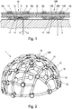
- Fig. 1 shows schematically the structure of two electrode arrangements with a common conductive body.
- Fig. 2 shows the structure of an electrode hood in its entirety.
- Fig. 3 an EEG measuring arrangement according to an embodiment of the invention is shown in more detail.
- Fig. 1 the head of a subject 2 is shown, to which an electrode arrangement 10 and a reference electrode arrangement 10R are connected.
- the first electrode arrangement 10 comprises an insulating layer 11 and two electrodes 12, 13, which lie opposite one another on the insulating layer 11.
- the first of the two opposite electrodes 12 lies on the side facing the head of the test person 2.
- the electrode arrangement 10 has a recess 17 for receiving conductive gel, which is delimited by the first electrode 10 and is open to the head of the subject 2. Conductive gel can be inserted into this recess 17, so that the first electrode 12 is in electrical contact with the head of the subject 2.
- each of the electrode arrangements 10 has a reference electrode 13, which is arranged on that side of the insulating layer 11 which lies opposite the measuring electrode 12.
- the reference electrode 13 is in electrically conductive contact with a conductive body 14 which bears against the reference electrode 13.
- the conductive body 14 is on the side of the reference electrode 13 facing away from the subject's head 2 arranged.
- the electrode hood 1 comprises a plurality of electrode arrangements 10, each with a separate insulating layer 11 and in each case separate electrodes 12, 13 lying opposite one another.
- a common conductive body 14 is available for all or part of the electrode arrangements 10.
- the conductive body 14R of the reference electrode arrangement 10R is electrically conductively connected to the conductive bodies 14 of the electrode arrangements 10.
- electrode arrangements 10 there is preferably also the possibility for the reference electrode arrangement 10R that a recess 17 delimited by the first electrode 12R and open towards the head of the test subject 2 is provided for receiving conductive gel.
- a particularly preferred embodiment of the invention is shown in more detail, which has a common conductive body 14 which is formed by a fluid, in particular a saline solution, which is in contact with the individual reference electrodes 13 and optionally the second electrode 13R.
- the conductive body 14 has a specific conductivity between 2 mS / cm and 40 mS / cm.
- each individual electrode arrangement 10 and the reference electrode arrangement 10R each have a container 15, 15R delimited by the reference electrode 13 or the second electrode 13R.
- the fluid forming the conductive body 14 is contained in this container.
- the individual containers 15, 15R of the electrode arrangement 10 or reference electrode arrangement 10R are connected to one another via hose connections 16 and thus form a communicating vessel.
- each of the electrode arrangements 10 and the reference electrode arrangements 10R each have a number of connections 15X for hose connections 16.
- the individual electrode arrangements of the present exemplary embodiment each have four hose connections 15X. However, the number of hose connections 15X can also vary, for example between two and ten.
- the electrode hood 1 is designed as a tubular network of electrode arrangements 10, 10R connected to one another in hose connections 16.
- the hose connections 16 can be reversibly detached from the connections 15X.
- the individual hose connections 16R in addition to the containers 15 of the electrode arrangements 10 also open into T-pieces.
- individual of the hose connections 16 are connected to an external inflow hose and an external outflow hose, via which fluid can be pumped into the electrode hood 1 or into the hose network or via which the fluid from the hose network or out the electrode hood 1 can be pumped out.
- FIG. 3 an EEG measuring arrangement 100 according to an embodiment of the invention is shown in more detail.
- This EEG measuring arrangement 100 comprises an electrode hood 1 as in FIG 1 and 2 and a measuring device 18 for measuring electrical voltages or voltage signals.
- the individual electrodes 12, 13 of the electrode arrangements 10 are electrically conductively connected to the measuring device 18.
- the electrodes 12R of the reference electrode arrangement 10R are also connected to the electrical measuring device 18 connected.
- the two electrodes 12R, 13R of the reference electrode arrangement 10R are connected to the reference potential of the measuring device 18.
- the measuring device 18 continuously determines the individual voltages applied to the electrodes 12, 13 and in this way provides signals V S , V ref .
- the EEG measuring arrangement 100 comprises a processing unit 19 which is connected downstream of the electrical measuring arrangement.
- This processing unit 19 relates the individual electrical signals V S , V ref received by the measuring device 18, which are applied to the measuring electrode 12 and the reference electrode 13 to the same electrode arrangement 10. In a preferred embodiment of the invention, it subtracts the two signals from one another and thus forms a cleaned signal V, which it makes available at its output.
Landscapes
- Health & Medical Sciences (AREA)
- Life Sciences & Earth Sciences (AREA)
- Surgery (AREA)
- Biophysics (AREA)
- Pathology (AREA)
- Engineering & Computer Science (AREA)
- Biomedical Technology (AREA)
- Heart & Thoracic Surgery (AREA)
- Medical Informatics (AREA)
- Molecular Biology (AREA)
- Physics & Mathematics (AREA)
- Animal Behavior & Ethology (AREA)
- General Health & Medical Sciences (AREA)
- Public Health (AREA)
- Veterinary Medicine (AREA)
- Nuclear Medicine, Radiotherapy & Molecular Imaging (AREA)
- Radiology & Medical Imaging (AREA)
- Cardiology (AREA)
- Measurement And Recording Of Electrical Phenomena And Electrical Characteristics Of The Living Body (AREA)
- Investigating Or Analyzing Materials By The Use Of Electric Means (AREA)
Description
- Die Erfindung betrifft eine Elektrodenhaube umfassend zumindest eine Elektrodenanordnung zum Anlegen an den Kopf eines Probanden gemäß dem Patentanspruch 1.
- Weiters betrifft die Erfindung eine EEG-Messanordnung gemäß Patentanspruch 8.
- Aus dem Stand der Technik ist eine große Anzahl unterschiedlicher Elektrodenhauben zum Anlegen an den Kopf eines Probanden bekannt. Die Schrift
EP 2 886 049 A1 offenbart ein Kleidungsstück mit einer Elektrodenanordnung zur Messung von Biopotentialen gemäß des Oberbegriffs des Anspruchs 1. Allgemein besteht bei solchen Elektrodenhauben der Nachteil, dass Messsignale an einzelnen Elektroden unterschiedlichen Störungen unterliegen. - Die Erfindung stellt sich die Aufgabe, eine Elektrodenhaube zur Verfügung zu stellen, die gegenüber Störungen, die von elektromagnetischen Feldern oder Strukturen außerhalb der Elektrodenhaube ausgehen, weitestgehend unbeeinflusst ist. Die vorliegende Erfindung löst diese Aufgabe bei einer Elektrodenhaube der eingangs genannten Art mit den Merkmalen des Patentanspruchs 1.
- Dabei ist vorgesehen, dass jede der Elektrodenanordnungen umfasst:
- eine Isolierschicht,
- zwei einander an der Isolierschicht gegenüberliegende Elektroden, nämlich eine erste, dem Kopf des Probanden zugewandte Messelektrode und eine dem Kopf des Probanden abgewandte Referenzelektrode, und
- einen an der Referenzelektrode anliegenden und mit dieser in elektrischem Kontakt stehenden leitfähiger Körper, der auf der dem Kopf des Probanden abgewandten Seite der Referenzelektrode angeordnet ist, und
- wobei die einzelnen leitfähigen Körper aller Elektrodenanordnungen elektrisch leitend miteinander verbunden sind.
- Hierbei ist besonders vorteilhaft, dass durch den durchgängigen leitfähigen Körper elektromagnetische Einflüsse von außerhalb der Elektrodenhaube die Messsignale sämtlicher Elektroden gleichermaßen beeinflussen, sodass durch einfache Kompensation Signale erhalten werden können, die von den äußeren elektromagnetischen Einflüssen bzw. Störungen vollkommen unabhängig sind.
- Besonders bevorzugt kann zum Anschluss an eine gemeinsame Systemmasse einer Messanordnung vorgesehen sein, dass eine Referenzelektrodenanordnung zum Anlegen an den Kopf des Probanden vorgesehen ist, die zumindest eine Elektrode aufweist, die dem Kopf des Probanden zugewandt ist und die elektrisch leitfähig mit den einzelnen leitfähigen Körpern der Elektrodenanordnungen verbunden ist.
- In einer baulich besonders einfach ausgestalteten Ausführungsform der Erfindung ist vorgesehen, dass der leitfähige Körper der Referenzelektrodenanordnung mit den leitfähigen Körpern aller Elektrodenanordnungen elektrisch leitend verbunden ist.
- Eine einfache Möglichkeit zur Schaffung eines durchgängigen leitfähigen Körpers sieht vor, dass der leitfähige Körper der oder jeder Elektrodenanordnung, gegebenenfalls der Referenzelektrodenanordnung, durch ein mit der Referenzelektrode und/oder mit der zweiten Elektrode in elektrischem Kontakt stehendes Fluid, insbesondere eine Kochsalzlösung, ausgebildet ist, und/oder dass der leitfähige Körper eine spezifische Leitfähigkeit von zwischen 2 mS/cm und 40mS/cm aufweist.
- Hierbei kann zur modularen Ausbildung einzelner Elektrodenanordnungen vorgesehen sein, dass die einzelnen Elektrodenanordnungen und gegebenenfalls die Referenzelektrodenanordnung jeweils einen von mit der Referenzelektrode und/oder der zweiten Elektrode begrenzten Behälter aufweist, in dem das Fluid enthalten ist, und dass die einzelnen Behälter miteinander, insbesondere über Schlauchverbindungen, in Verbindung stehen und derart kommunizierende Gefäße bilden.
- Um eine besonders einfache modulare Anpassung der Elektrodenhaube an unterschiedliche Kopfformen vorzusehen, kann vorgesehen sein, dass die Elektrodenhaube als schlauchförmiges Netz von miteinander über Schlauchverbindungen verbundenen Elektrodenanordnungen ausgebildet ist, wobei die einzelnen Behälter der Elektrodenanordnungen Anschlüsse zum, insbesondere reversiblen, Verbinden mit Schlauchverbindungen aufweisen.
- Eine besonders vorteilhafte Kontaktierung des Kopfes des Probanden mit der Elektrodenhaube sieht vor, dass zumindest eine oder jede der Elektrodenanordnungen, und gegebenenfalls die Referenzelektrodenanordnung, eine von der Messelektrode oder der ersten Elektrode begrenzte und zum Kopf des Probanden hin offene Ausnehmung zur Aufnahme von leitfähigem Gel aufweist.
- Eine vorteilhafte Messanordnung umfasst eine erfindungsgemäße Elektrodenhaube sowie eine Messeinrichtung zur Bestimmung der an den Elektroden anliegenden Spannungen. Besonders vorteilhaft kann zur Weiterverarbeitung der Signale vorgesehen sein, dass eine Verarbeitungseinheit vorgesehen ist, die diejenigen elektrischen Signale, die an der Messelektrode und der Referenzelektrode jeweils derselben Elektrodenanordnung anliegen, miteinander in Beziehung setzt, insbesondere die beiden Signale voneinander abzieht, und derart ein bereinigtes Signal für die Elektrodenanordnung erstellt.
- Besonders einfach kann zur Schaffung eines Bezugspotentials vorgesehen sein, dass die zumindest eine Elektrode oder die beiden Elektroden der Referenzelektrodenanordnung mit einem Bezugspotential der Messeinrichtung verbunden sind.
- Eine bevorzugte Ausführungsform der Erfindung wird anhand der folgenden Zeichnungsfiguren näher dargestellt.
-
Fig. 1 zeigt schematisch den Aufbau zweier Elektrodenanordnungen mit einem gemeinsamen leitfähigen Körper.Fig. 2 zeigt den Aufbau einer Elektrodenhaube in ihrer Gesamtheit. InFig. 3 ist eine EEG-Messanordnung entsprechend einem Ausführungsbeispiel der Erfindung näher dargestellt. - In
Fig. 1 ist der Kopf eines Probanden 2 dargestellt, an den eine Elektrodenanordnung 10 sowie eine Referenzelektrodenanordnung 10R angeschlossen sind. Die erste Elektrodenanordnung 10 umfasst eine Isolierschicht 11 sowie zwei Elektroden 12, 13, die einander an der Isolierschicht 11 gegenüberliegen. Die erste der beiden gegenüberliegenden Elektroden 12 liegt an der dem Kopf des Probanden 2 zugewandten Seite. Die Elektrodenanordnung 10 weist eine Ausnehmung 17 zur Aufnahme von leitfähigem Gel auf, die von der ersten Elektrode 10 begrenzt ist und zum Kopf des Probanden 2 hin offen ist. In diese Ausnehmung 17 kann leitfähiges Gel eingefügt werden, sodass die erste Elektrode 12 mit dem Kopf des Probanden 2 in elektrischem Kontakt steht. - Weiters verfügt jede der Elektrodenanordnungen 10 jeweils über eine Referenzelektrode 13, die an derjenigen Seite der Isolierschicht 11 angeordnet ist, die der Messelektrode 12 gegenüberliegt. Die Referenzelektrode 13 steht mit einem leitfähigen Körper 14, der an der Referenzelektrode 13 anliegt, in elektrisch leitfähigem Kontakt. Der leitfähige Körper 14 ist auf der dem Kopf des Probanden 2 abgewandten Seite der Referenzelektrode 13 angeordnet. Die Elektrodenhaube 1 umfasst mehrere Elektrodenanordnungen 10 mit jeweils separater Isolierschicht 11 und jeweils separaten einander gegenüberliegenden Elektroden 12, 13. Für sämtliche oder für einen Teil der Elektrodenanordnungen 10 steht jeweils ein gemeinsamer leitfähiger Körper 14 zur Verfügung. Alternativ kann auch vorgesehen sein, dass für jede der Elektrodenanordnungen 10 jeweils ein separater leitfähiger Körper 14 besteht und sämtliche der leitfähigen Körper 14 der einzelnen Elektrodenanordnungen 10 miteinander elektrisch leitend verbunden sind.
- Bei der in
Fig. 1 dargestellten Ausführungsform der Erfindung ist neben der Elektrodenanordnung 10 auch eine Referenzelektrodenanordnung 10R zum Anlegen an den Kopf des Probenden 2 vorgesehen. Die Referenzelektrodenanordnung 10R ist im wesentlichen so aufgebaut wie die Elektrodenanordnung 10 und weist insbesondere eine Elektrode 12R auf, die dem Kopf des Probanden 2 zugewandt ist. Insgesamt ist es jedoch lediglich erforderlich, dass eine einzige Elektrode 12R auf der dem Kopf des Probanden 2 zugewandten Seite vorgesehen ist, die, auf welche Art auch immer, leitfähig mit den einzelnen leitfähigen Körpern der Referenzelektrodenanordnung 10R verbunden ist. Besonders vorteilhaft kann eine solche Referenzelektrodenanordnung 10R realisiert werden, wenn diese ebenso wie die einzelnen Elektrodenanordnungen 10 ausgebildet ist, wobei die Referenzelektrodenanordnung 10R umfasst: - eine Isolierschicht 11,
- zwei einander an der Isolierschicht 11 gegenüberliegende Elektroden 12R, 13R, nämlich eine erste, dem Kopf des Probanden 2 zugewandte erste Elektrode 12R und eine dem Kopf des Probanden 2 abgewandte zweite Elektrode 13R, wobei die erste und zweite Elektrode 13R miteinander elektrisch leitend verbunden sind,
- einen an der zweiten Elektrode 13R anliegenden und mit dieser in elektrischem Kontakt stehenden leitfähigen Körper 14R, der auf der dem Kopf des Probanden 2 abgewandten Seite der zweiten Elektrode 13R angeordnet ist.
- Der leitfähige Körper 14R der Referenzelektrodenanordnung 10R ist mit den leitfähigen Körpern 14 der Elektrodenanordnungen 10 elektrisch leitend verbunden.
- Wie auch in Hinblick auf Elektrodenanordnungen 10 eingangs dargestellt, besteht auch für die Referenzelektrodenanordnung 10R bevorzugt die Möglichkeit, dass eine von der ersten Elektrode 12R begrenzte und zum Kopf des Probanden 2 hin offene Ausnehmung 17 zur Aufnahme von leitfähigem Gel vorgesehen ist.
- In den
Fig. 1 und 2 ist eine besonders bevorzugte Ausführungsform der Erfindung näher dargestellt, die über einen gemeinsamen leitfähigen Körper 14 verfügt, der durch ein mit den einzelnen Referenzelektroden 13 sowie gegebenenfalls der zweiten Elektrode 13R in Kontakt stehendem Fluid, insbesondere einer Kochsalzlösung ausgebildet ist. Der leitfähige Körper 14 weist in dieser bevorzugten Ausführungsform der Erfindung eine spezifische Leitfähigkeit zwischen 2 mS/cm und 40 mS/cm auf. - Wie in
Fig. 1 dargestellt, weist jede einzelne Elektrodenanordnung 10 sowie die Referenzelektrodenanordnung 10R jeweils einen von mit der Referenzelektrode 13 bzw. der zweiten Elektrode 13R begrenzten Behälter 15, 15R auf. In diesem Behälter ist das den leitfähigen Körper 14 bildende Fluid enthalten. Die einzelnen Behälter 15, 15R der Elektrodenanordnung 10 bzw. Referenzelektrodenanordnung 10R sind miteinander über Schlauchverbindungen 16 verbunden und bilden derart ein kommunizierendes Gefäß. Wie inFig. 2 dargestellt, weist jede der Elektrodenanordnungen 10 bzw. der Referenzelektrodenanordnungen 10R jeweils eine Anzahl von Anschlüssen 15X für Schlauchverbindungen 16 auf. Die einzelnen Elektrodenanordnungen des vorliegenden Ausführungsbeispiels weisen jeweils vier Schlauchverbindungen 15X auf. Die Anzahl der Schlauchverbindungen 15X kann aber auch variieren beispielsweise zwischen zwei und zehn liegen. Die Elektrodenhaube 1 ist als schlauchförmiges Netz von miteinander in Schlauchverbindungen 16 verbundenen Elektrodenanordnungen 10, 10R ausgebildet. In dieser bevorzugten Ausführungsform der Erfindung können die Schlauchverbindungen 16 reversibel von den Anschlüssen 15X gelöst werden. Wie inFig. 2 dargestellt, besteht die Möglichkeit, dass die einzelnen Schlauchverbindungen 16R neben den Behältern 15 der Elektrodenanordnungen 10 auch in T-Stücke münden. Darüber hinaus besteht auch die Möglichkeit, dass einzelne der Schlauchverbindungen 16 mit einem externen Zuflussschlauch und einem externen Abflussschlauch verbunden sind, über den Fluid in die Elektrodenhaube 1 bzw. in das Schlauchnetzwerk gepumpt werden kann bzw. über den das Fluid aus dem Schlauchnetzwerk bzw. aus der Elektrodenhaube 1 abgepumpt werden kann. - In
Fig. 3 ist eine EEG-Messanordnung 100 entsprechend einem Ausführungsbeispiel der Erfindung näher dargestellt. Diese EEG-Messanordnung 100 umfasst eine Elektrodenhaube 1 wie inFig. 1 und 2 dargestellt sowie eine Messeinrichtung 18 zur Messung von elektrischen Spannungen bzw. Spannungssignalen. Die einzelnen Elektroden 12, 13 der Elektrodenanordnungen 10 sind elektrisch leitfähig mit der Messeinrichtung 18 verbunden. Auch die Elektroden 12R der Referenzelektrodenanordnung 10R sind mit der elektrischen Messeinrichtung 18 verbunden. Im konkreten Fall sind die beiden Elektroden 12R, 13R der Referenzelektrodenanordnung 10R mit dem Bezugspotential der Messeinrichtung 18 verbunden. Die Messeinrichtung 18 ermittelt laufend die einzelnen an den Elektroden 12, 13 anliegenden Spannungen und stellt derart Signale VS, Vref zur Verfügung. Die EEG-Messanordnung 100 umfasst eine Verarbeitungseinheit 19, die der elektrischen Messanordnung nachgeschaltet ist. Diese Verarbeitungseinheit 19 setzt die einzelnen von der Messeinrichtung 18 aufgenommenen elektrischen Signale VS, Vref, die an der Messelektrode 12 und der Referenzelektrode 13 jeweils derselben Elektrodenanordnung 10 anliegen, miteinander in Bezug. Bei einer bevorzugten Ausführungsform der Erfindung zieht sie die beiden Signale voneinander ab und bildet derart ein bereinigtes Signal V, das sie an ihrem Ausgang zur Verfügung stellt.
Claims (11)
- Elektrodenhaube (1) umfassend zumindest eine Elektrodenanordnung (10) zum Anlegen an den Kopf eines Probanden (2),- wobei jede der Elektrodenanordnungen (10) umfasst:- eine Isolierschicht (11),- zwei einander an der Isolierschicht (11) gegenüberliegende Elektroden (12, 13), nämlich eine erste, dem Kopf des Probanden (2) zugewandte Messelektrode (12) und eine dem Kopf des Probanden (2) abgewandte Referenzelektrode (13), und- einen an der Referenzelektrode (13) anliegenden und mit dieser in elektrischem Kontakt stehenden leitfähiger Körper (14), der auf der dem Kopf des Probanden (2) abgewandten Seite der Referenzelektrode (13) angeordnet ist, und- wobei die einzelnen leitfähigen Körper (14) aller Elektrodenanordnungen (10) elektrisch leitend miteinander verbunden sind,
dadurch gekennzeichnet, dass der leitfähige Körper (14) zumindest einer oder jeder Elektrodenanordnung (10) durch ein mit der Referenzelektrode (13) in elektrischem Kontakt stehendes Fluid, insbesondere eine Kochsalzlösung, ausgebildet ist. - Elektrodenhaube (1) nach Anspruch 1, dadurch gekennzeichnet, dass eine Referenzelektrodenanordnung (10R) zum Anlegen an den Kopf des Probanden (2) vorgesehen ist, die zumindest eine Elektrode aufweist, die dem Kopf des Probanden (2) zugewandt ist und die elektrisch leitfähig mit den einzelnen leitfähigen Körpern (14) der Elektrodenanordnungen (10) verbunden ist.
- Elektrodenhaube (1) nach Anspruch 2, dadurch gekennzeichnet, dass die Referenzelektrodenanordnung (10R) umfasst:- eine Isolierschicht (11R),- zwei einander an der Isolierschicht (11R) gegenüberliegende Elektroden (12R, 13R), nämlich eine erste, dem Kopf des Probanden (2) zugewandte erste Elektrode (12R) und eine dem Kopf des Probanden (2) abgewandte zweite Elektrode (13R), wobei die erste und zweite Elektrode (12R, 13R) miteinander elektrisch leitend verbunden sind,- einen an der zweiten Elektrode (13) anliegenden und mit dieser in elektrischem Kontakt stehenden leitfähigen Körper (14R), der auf der dem Kopf des Probanden (2) abgewandten Seite der zweiten Elektrode (13R) angeordnet ist,wobei der leitfähige Körper (14R) der Referenzelektrodenanordnung (10R) mit den leitfähigen Körpern (14) aller Elektrodenanordnungen (10) elektrisch leitend verbunden ist.
- Elektrodenhaube (1) nach Anspruch 3, dadurch gekennzeichnet, dass der leitfähige Körper (14R) der Referenzelektrodenanordnung (10R) durch ein mit der zweiten Elektrode (13R) in elektrischem Kontakt stehendes Fluid, insbesondere eine Kochsalzlösung, ausgebildet ist.
- Elektrodenhaube (1) nach einem der vorangehenden Ansprüche, dadurch gekennzeichnet,- dass die einzelnen Elektrodenanordnungen (10) und gegebenenfalls die Referenzelektrodenanordnung (10R) jeweils einen von mit der Referenzelektrode (13) und/oder der zweiten Elektrode (13R) begrenzten Behälter (15, 15R) aufweist, in dem das Fluid enthalten ist, und- dass die einzelnen Behälter (15) miteinander, insbesondere über Schlauchverbindungen (16), in Verbindung stehen und derart kommunizierende Gefäße bilden.
- Elektrodenhaube (1) nach Anspruch 5, dadurch gekennzeichnet, dass die Elektrodenhaube (1) als schlauchförmiges Netz von miteinander über Schlauchverbindungen (16) verbundenen Elektrodenanordnungen (10, 10R) ausgebildet ist, wobei die einzelnen Behälter (15) der Elektrodenanordnungen (10, 10R) Anschlüsse (15x) zum, insbesondere reversiblen, Verbinden mit Schlauchverbindungen (16) aufweisen.
- Elektrodenhaube (1) nach einem der vorangehenden Ansprüche, dadurch gekennzeichnet, dass zumindest eine oder jede der Elektrodenanordnungen (10), und gegebenenfalls die Referenzelektrodenanordnung (10R), eine von der Messelektrode (12) oder der ersten Elektrode (12R) begrenzte und zum Kopf des Probanden (2) hin offene Ausnehmung (17) zur Aufnahme von leitfähigem Gel aufweist.
- Elektrodenhaube (1) nach einem der vorangehenden Ansprüche, dadurch gekennzeichnet, dass der leitfähige Körper (14, 14R) eine spezifische Leitfähigkeit von zwischen 2 mS/cm und 40 mS/cm aufweist.
- EEG-Messanordnung (100) umfassend eine Elektrodenhaube (1) nach einem der vorangehenden Ansprüche und eine Messeinrichtung (18), dadurch gekennzeichnet, dass die einzelnen Elektroden (12, 13) der Elektrodenanordnungen (10), und gegebenenfalls die zumindest eine Elektrode (12R) der Referenzelektrodenanordnung (10R), elektrisch leitfähig mit der elektrischen Messeinrichtung (18), insbesondere zur Messung der an den einzelnen Elektroden (12, 13) anliegenden Spannungen und/oder Signalen (VS, Vref), verbunden sind.
- EEG-Messanordnung (100) nach Anspruch 9, dadurch gekennzeichnet, dass eine Verarbeitungseinheit (19) vorgesehen ist, die diejenigen elektrischen Signale (VS, Vref), die an der Messelektrode (12) und der Referenzelektrode (13) jeweils derselben Elektrodenanordnung (10) anliegen, miteinander in Beziehung setzt, insbesondere die beiden Signale (VS, Vref) voneinander abzieht, und derart ein bereinigtes Signal (V) für die Elektrodenanordnung (10) erstellt.
- EEG-Messanordnung (100) nach Anspruch 9 oder 10, dadurch gekennzeichnet, dass die zumindest eine Elektrode (12R) oder die beiden Elektroden (12R, 13R) der Referenzelektrodenanordnung (10R) mit einem Bezugspotential der Messeinrichtung (18) verbunden sind.
Applications Claiming Priority (2)
| Application Number | Priority Date | Filing Date | Title |
|---|---|---|---|
| ATA50198/2016A AT518321B1 (de) | 2016-03-09 | 2016-03-09 | Elektrodenhaube |
| PCT/AT2017/060056 WO2017152206A1 (de) | 2016-03-09 | 2017-03-06 | Elektrodenhaube |
Publications (2)
| Publication Number | Publication Date |
|---|---|
| EP3426142A1 EP3426142A1 (de) | 2019-01-16 |
| EP3426142B1 true EP3426142B1 (de) | 2020-05-13 |
Family
ID=58346997
Family Applications (1)
| Application Number | Title | Priority Date | Filing Date |
|---|---|---|---|
| EP17711072.3A Revoked EP3426142B1 (de) | 2016-03-09 | 2017-03-06 | Elektrodenhaube |
Country Status (5)
| Country | Link |
|---|---|
| US (1) | US10758148B2 (de) |
| EP (1) | EP3426142B1 (de) |
| AT (1) | AT518321B1 (de) |
| ES (1) | ES2805063T3 (de) |
| WO (1) | WO2017152206A1 (de) |
Families Citing this family (4)
| Publication number | Priority date | Publication date | Assignee | Title |
|---|---|---|---|---|
| TR201722875A2 (tr) * | 2017-12-29 | 2019-07-22 | Dokuz Eyluel Ueniversitesi Rektoerluegue | Gürültü engelleyi̇ci̇ eeg kayit başliği |
| CN108378847A (zh) * | 2018-05-10 | 2018-08-10 | 深圳柏德医疗科技有限公司 | 一种免清洗脑电帽 |
| CN115243617B (zh) | 2019-12-23 | 2025-10-28 | 测验有限公司 | 电极贴片和连接系统 |
| WO2021140441A1 (en) * | 2020-01-10 | 2021-07-15 | Magstim Group, Incorporated | Head size adaptation mechanism for an eeg net |
Citations (7)
| Publication number | Priority date | Publication date | Assignee | Title |
|---|---|---|---|---|
| FR2627975A1 (fr) | 1988-03-07 | 1989-09-08 | Prugne Pascale | Piece de jonction, pour le positionnement des electrodes dans la prise d'un electro-encephalogramme |
| US5038782A (en) | 1986-12-16 | 1991-08-13 | Sam Technology, Inc. | Electrode system for brain wave detection |
| US20090054758A1 (en) | 2005-03-03 | 2009-02-26 | William James Ross Dunseath | Apparatus and Method for Reducing Interference |
| US20090099473A1 (en) | 2005-11-10 | 2009-04-16 | William James Ross Dunseath | Apparatus and Method for Acquiring a Signal |
| WO2011038103A1 (en) | 2009-09-25 | 2011-03-31 | Neuronetrix Solutions, Llc | Electrode system with rigid-flex circuit |
| US20130172721A1 (en) | 2007-11-06 | 2013-07-04 | Hydrodot, Inc. | Device and method for performing electroencephalograpy |
| EP2886049A1 (de) | 2013-12-20 | 2015-06-24 | CSEM Centre Suisse d'Electronique et de Microtechnique SA | Messvorrichtung zur Messung der Bioimpedanz und/oder des Biopotenzials eines menschlichen oder tierischen Körpers |
Family Cites Families (2)
| Publication number | Priority date | Publication date | Assignee | Title |
|---|---|---|---|---|
| US10188307B2 (en) * | 2012-02-23 | 2019-01-29 | Bio-Signal Group Corp. | Shielded multi-channel EEG headset systems and methods |
| GB2522195A (en) | 2014-01-15 | 2015-07-22 | Imp Innovations Ltd | Biosensing electrodes |
-
2016
- 2016-03-09 AT ATA50198/2016A patent/AT518321B1/de not_active IP Right Cessation
-
2017
- 2017-03-06 EP EP17711072.3A patent/EP3426142B1/de not_active Revoked
- 2017-03-06 US US16/083,579 patent/US10758148B2/en not_active Expired - Fee Related
- 2017-03-06 ES ES17711072T patent/ES2805063T3/es active Active
- 2017-03-06 WO PCT/AT2017/060056 patent/WO2017152206A1/de not_active Ceased
Patent Citations (7)
| Publication number | Priority date | Publication date | Assignee | Title |
|---|---|---|---|---|
| US5038782A (en) | 1986-12-16 | 1991-08-13 | Sam Technology, Inc. | Electrode system for brain wave detection |
| FR2627975A1 (fr) | 1988-03-07 | 1989-09-08 | Prugne Pascale | Piece de jonction, pour le positionnement des electrodes dans la prise d'un electro-encephalogramme |
| US20090054758A1 (en) | 2005-03-03 | 2009-02-26 | William James Ross Dunseath | Apparatus and Method for Reducing Interference |
| US20090099473A1 (en) | 2005-11-10 | 2009-04-16 | William James Ross Dunseath | Apparatus and Method for Acquiring a Signal |
| US20130172721A1 (en) | 2007-11-06 | 2013-07-04 | Hydrodot, Inc. | Device and method for performing electroencephalograpy |
| WO2011038103A1 (en) | 2009-09-25 | 2011-03-31 | Neuronetrix Solutions, Llc | Electrode system with rigid-flex circuit |
| EP2886049A1 (de) | 2013-12-20 | 2015-06-24 | CSEM Centre Suisse d'Electronique et de Microtechnique SA | Messvorrichtung zur Messung der Bioimpedanz und/oder des Biopotenzials eines menschlichen oder tierischen Körpers |
Non-Patent Citations (4)
| Title |
|---|
| "Geschichte der Kopfbedeckungen", Retrieved from the Internet <URL:https://austria-forum.org/af/Heimatlexikon/Geschichte_der_Kopfbedeckungen> |
| CHOWDHURY ET AL.: "Reference layer artefact subtraction (RLAS): A novel method of minimizing EEG artefacts during simultaneous fMRI", NEUROIMAGE, vol. 84, 2014, pages 307 - 319, XP028802488 |
| LUO ET AL.: "Ballistocardiogram artifact removal with a reference layer and standard EEG cap", JOURNAL OF NEUROSCIENCE METHODS, vol. 233, 2014, pages 137 - 149, XP029009639 |
| XIA ET AL.: "Removing ballistocardiogram (BCG) artifact from full-scalp EEG acquired inside the MR scanner with Orthogonal Matching Pursuit (OMP)", FRONTIERS IN NEUROSCIENCE, vol. 8, 218, 29 July 2014 (2014-07-29), pages 1 - 12, XP055777977 |
Also Published As
| Publication number | Publication date |
|---|---|
| EP3426142A1 (de) | 2019-01-16 |
| WO2017152206A1 (de) | 2017-09-14 |
| AT518321A1 (de) | 2017-09-15 |
| US10758148B2 (en) | 2020-09-01 |
| ES2805063T3 (es) | 2021-02-10 |
| AT518321B1 (de) | 2019-03-15 |
| US20190082994A1 (en) | 2019-03-21 |
Similar Documents
| Publication | Publication Date | Title |
|---|---|---|
| DE857087C (de) | Anschlussglied zum Anschliessen einer koaxialen Leitung oder zum Verbinden zweier koaxialer Leitungen | |
| DE3022115C2 (de) | Sicherungs- und Verteilerkasten für Kraftfahrzeuge | |
| EP0416159A1 (de) | Mehrteilige flächenhafte Elektrode für ein HF-Chirugie-gerät | |
| DE3544483A1 (de) | Neutrale elektrode sowie anschlussklemme dafuer | |
| DE112018004830T5 (de) | Strommessvorrichtung | |
| AT518321B1 (de) | Elektrodenhaube | |
| DE20007260U1 (de) | Kondensator mit Stromverteilungsfähigkeit für ein Autoradio | |
| EP3463568B1 (de) | Prüfvorrichtung zum überprüfen wenigstens einer ersten medizinischen elektrode | |
| EP0595001B1 (de) | Kabelanordnung | |
| DE2046430C3 (de) | Prüfanordnung zum Anschalten von zu prüfenden Ausrüstungen, wie Relaisschutz- und Automatikausrüstungen, an Prüfapparate | |
| EP4066321B1 (de) | Buchsenkontakt mit seitlichem kabelabgang | |
| DE855129C (de) | Schalter und Abschwaecher | |
| DE102020203380A1 (de) | Vorrichtung und verfahren zum verbinden von stromkabeln | |
| DE2509126A1 (de) | Modularer hochfrequenz-mehrfachschalter | |
| EP3266071B1 (de) | Verbindungsvorrichtung | |
| DE3722059C1 (en) | Measuring device for fluid jets | |
| DE102015213240B4 (de) | Schutzschalter | |
| DE102015213631A1 (de) | Schaltungsplatine | |
| DE3411323A1 (de) | Schaltklappe | |
| DE202011107955U1 (de) | Elektrohydraulischer Stellantrieb | |
| EP2073314A1 (de) | Anordnung zum elektrisch leitenden Verbinden von elektrischen Leltern | |
| DE956701C (de) | Anordnung zur Anzapfung von Koaxialkabeln | |
| DE10208702C1 (de) | Ohmsch-kapazitiver Spannungsteiler | |
| DE1640614C3 (de) | Dreifachkupplung für Schutzkontaktstecker | |
| DE1591843C3 (de) | Kapazitiver Tastkopf zum Anbringen an einen isolierten elektrischen Leiter |
Legal Events
| Date | Code | Title | Description |
|---|---|---|---|
| STAA | Information on the status of an ep patent application or granted ep patent |
Free format text: STATUS: UNKNOWN |
|
| STAA | Information on the status of an ep patent application or granted ep patent |
Free format text: STATUS: THE INTERNATIONAL PUBLICATION HAS BEEN MADE |
|
| PUAI | Public reference made under article 153(3) epc to a published international application that has entered the european phase |
Free format text: ORIGINAL CODE: 0009012 |
|
| STAA | Information on the status of an ep patent application or granted ep patent |
Free format text: STATUS: REQUEST FOR EXAMINATION WAS MADE |
|
| 17P | Request for examination filed |
Effective date: 20180905 |
|
| AK | Designated contracting states |
Kind code of ref document: A1 Designated state(s): AL AT BE BG CH CY CZ DE DK EE ES FI FR GB GR HR HU IE IS IT LI LT LU LV MC MK MT NL NO PL PT RO RS SE SI SK SM TR |
|
| AX | Request for extension of the european patent |
Extension state: BA ME |
|
| DAV | Request for validation of the european patent (deleted) | ||
| DAX | Request for extension of the european patent (deleted) | ||
| GRAP | Despatch of communication of intention to grant a patent |
Free format text: ORIGINAL CODE: EPIDOSNIGR1 |
|
| STAA | Information on the status of an ep patent application or granted ep patent |
Free format text: STATUS: GRANT OF PATENT IS INTENDED |
|
| INTG | Intention to grant announced |
Effective date: 20200212 |
|
| GRAS | Grant fee paid |
Free format text: ORIGINAL CODE: EPIDOSNIGR3 |
|
| GRAA | (expected) grant |
Free format text: ORIGINAL CODE: 0009210 |
|
| STAA | Information on the status of an ep patent application or granted ep patent |
Free format text: STATUS: THE PATENT HAS BEEN GRANTED |
|
| AK | Designated contracting states |
Kind code of ref document: B1 Designated state(s): AL AT BE BG CH CY CZ DE DK EE ES FI FR GB GR HR HU IE IS IT LI LT LU LV MC MK MT NL NO PL PT RO RS SE SI SK SM TR |
|
| REG | Reference to a national code |
Ref country code: GB Ref legal event code: FG4D Free format text: NOT ENGLISH |
|
| REG | Reference to a national code |
Ref country code: CH Ref legal event code: EP |
|
| REG | Reference to a national code |
Ref country code: DE Ref legal event code: R096 Ref document number: 502017005249 Country of ref document: DE |
|
| REG | Reference to a national code |
Ref country code: AT Ref legal event code: REF Ref document number: 1269145 Country of ref document: AT Kind code of ref document: T Effective date: 20200615 |
|
| REG | Reference to a national code |
Ref country code: LT Ref legal event code: MG4D |
|
| REG | Reference to a national code |
Ref country code: NL Ref legal event code: MP Effective date: 20200513 |
|
| PG25 | Lapsed in a contracting state [announced via postgrant information from national office to epo] |
Ref country code: IS Free format text: LAPSE BECAUSE OF FAILURE TO SUBMIT A TRANSLATION OF THE DESCRIPTION OR TO PAY THE FEE WITHIN THE PRESCRIBED TIME-LIMIT Effective date: 20200913 Ref country code: PT Free format text: LAPSE BECAUSE OF FAILURE TO SUBMIT A TRANSLATION OF THE DESCRIPTION OR TO PAY THE FEE WITHIN THE PRESCRIBED TIME-LIMIT Effective date: 20200914 Ref country code: FI Free format text: LAPSE BECAUSE OF FAILURE TO SUBMIT A TRANSLATION OF THE DESCRIPTION OR TO PAY THE FEE WITHIN THE PRESCRIBED TIME-LIMIT Effective date: 20200513 Ref country code: SE Free format text: LAPSE BECAUSE OF FAILURE TO SUBMIT A TRANSLATION OF THE DESCRIPTION OR TO PAY THE FEE WITHIN THE PRESCRIBED TIME-LIMIT Effective date: 20200513 Ref country code: LT Free format text: LAPSE BECAUSE OF FAILURE TO SUBMIT A TRANSLATION OF THE DESCRIPTION OR TO PAY THE FEE WITHIN THE PRESCRIBED TIME-LIMIT Effective date: 20200513 Ref country code: GR Free format text: LAPSE BECAUSE OF FAILURE TO SUBMIT A TRANSLATION OF THE DESCRIPTION OR TO PAY THE FEE WITHIN THE PRESCRIBED TIME-LIMIT Effective date: 20200814 Ref country code: NO Free format text: LAPSE BECAUSE OF FAILURE TO SUBMIT A TRANSLATION OF THE DESCRIPTION OR TO PAY THE FEE WITHIN THE PRESCRIBED TIME-LIMIT Effective date: 20200813 |
|
| REG | Reference to a national code |
Ref country code: DE Ref legal event code: R079 Ref document number: 502017005249 Country of ref document: DE Free format text: PREVIOUS MAIN CLASS: A61B0005047800 Ipc: A61B0005291000 |
|
| PG25 | Lapsed in a contracting state [announced via postgrant information from national office to epo] |
Ref country code: BG Free format text: LAPSE BECAUSE OF FAILURE TO SUBMIT A TRANSLATION OF THE DESCRIPTION OR TO PAY THE FEE WITHIN THE PRESCRIBED TIME-LIMIT Effective date: 20200813 Ref country code: RS Free format text: LAPSE BECAUSE OF FAILURE TO SUBMIT A TRANSLATION OF THE DESCRIPTION OR TO PAY THE FEE WITHIN THE PRESCRIBED TIME-LIMIT Effective date: 20200513 Ref country code: HR Free format text: LAPSE BECAUSE OF FAILURE TO SUBMIT A TRANSLATION OF THE DESCRIPTION OR TO PAY THE FEE WITHIN THE PRESCRIBED TIME-LIMIT Effective date: 20200513 Ref country code: LV Free format text: LAPSE BECAUSE OF FAILURE TO SUBMIT A TRANSLATION OF THE DESCRIPTION OR TO PAY THE FEE WITHIN THE PRESCRIBED TIME-LIMIT Effective date: 20200513 |
|
| PG25 | Lapsed in a contracting state [announced via postgrant information from national office to epo] |
Ref country code: AL Free format text: LAPSE BECAUSE OF FAILURE TO SUBMIT A TRANSLATION OF THE DESCRIPTION OR TO PAY THE FEE WITHIN THE PRESCRIBED TIME-LIMIT Effective date: 20200513 Ref country code: NL Free format text: LAPSE BECAUSE OF FAILURE TO SUBMIT A TRANSLATION OF THE DESCRIPTION OR TO PAY THE FEE WITHIN THE PRESCRIBED TIME-LIMIT Effective date: 20200513 |
|
| PG25 | Lapsed in a contracting state [announced via postgrant information from national office to epo] |
Ref country code: DK Free format text: LAPSE BECAUSE OF FAILURE TO SUBMIT A TRANSLATION OF THE DESCRIPTION OR TO PAY THE FEE WITHIN THE PRESCRIBED TIME-LIMIT Effective date: 20200513 Ref country code: SM Free format text: LAPSE BECAUSE OF FAILURE TO SUBMIT A TRANSLATION OF THE DESCRIPTION OR TO PAY THE FEE WITHIN THE PRESCRIBED TIME-LIMIT Effective date: 20200513 Ref country code: EE Free format text: LAPSE BECAUSE OF FAILURE TO SUBMIT A TRANSLATION OF THE DESCRIPTION OR TO PAY THE FEE WITHIN THE PRESCRIBED TIME-LIMIT Effective date: 20200513 Ref country code: RO Free format text: LAPSE BECAUSE OF FAILURE TO SUBMIT A TRANSLATION OF THE DESCRIPTION OR TO PAY THE FEE WITHIN THE PRESCRIBED TIME-LIMIT Effective date: 20200513 Ref country code: CZ Free format text: LAPSE BECAUSE OF FAILURE TO SUBMIT A TRANSLATION OF THE DESCRIPTION OR TO PAY THE FEE WITHIN THE PRESCRIBED TIME-LIMIT Effective date: 20200513 |
|
| REG | Reference to a national code |
Ref country code: DE Ref legal event code: R026 Ref document number: 502017005249 Country of ref document: DE |
|
| REG | Reference to a national code |
Ref country code: ES Ref legal event code: FG2A Ref document number: 2805063 Country of ref document: ES Kind code of ref document: T3 Effective date: 20210210 |
|
| PLBI | Opposition filed |
Free format text: ORIGINAL CODE: 0009260 |
|
| PG25 | Lapsed in a contracting state [announced via postgrant information from national office to epo] |
Ref country code: SK Free format text: LAPSE BECAUSE OF FAILURE TO SUBMIT A TRANSLATION OF THE DESCRIPTION OR TO PAY THE FEE WITHIN THE PRESCRIBED TIME-LIMIT Effective date: 20200513 Ref country code: PL Free format text: LAPSE BECAUSE OF FAILURE TO SUBMIT A TRANSLATION OF THE DESCRIPTION OR TO PAY THE FEE WITHIN THE PRESCRIBED TIME-LIMIT Effective date: 20200513 |
|
| PLAX | Notice of opposition and request to file observation + time limit sent |
Free format text: ORIGINAL CODE: EPIDOSNOBS2 |
|
| 26 | Opposition filed |
Opponent name: WEISER-LOBAO, PHILIPP Effective date: 20210203 |
|
| PGFP | Annual fee paid to national office [announced via postgrant information from national office to epo] |
Ref country code: FR Payment date: 20210324 Year of fee payment: 5 |
|
| PG25 | Lapsed in a contracting state [announced via postgrant information from national office to epo] |
Ref country code: SI Free format text: LAPSE BECAUSE OF FAILURE TO SUBMIT A TRANSLATION OF THE DESCRIPTION OR TO PAY THE FEE WITHIN THE PRESCRIBED TIME-LIMIT Effective date: 20200513 |
|
| PGFP | Annual fee paid to national office [announced via postgrant information from national office to epo] |
Ref country code: DE Payment date: 20210319 Year of fee payment: 5 |
|
| PGFP | Annual fee paid to national office [announced via postgrant information from national office to epo] |
Ref country code: ES Payment date: 20210525 Year of fee payment: 5 |
|
| PG25 | Lapsed in a contracting state [announced via postgrant information from national office to epo] |
Ref country code: MC Free format text: LAPSE BECAUSE OF FAILURE TO SUBMIT A TRANSLATION OF THE DESCRIPTION OR TO PAY THE FEE WITHIN THE PRESCRIBED TIME-LIMIT Effective date: 20200513 |
|
| REG | Reference to a national code |
Ref country code: CH Ref legal event code: PL |
|
| RDAF | Communication despatched that patent is revoked |
Free format text: ORIGINAL CODE: EPIDOSNREV1 |
|
| REG | Reference to a national code |
Ref country code: DE Ref legal event code: R103 Ref document number: 502017005249 Country of ref document: DE Ref country code: DE Ref legal event code: R064 Ref document number: 502017005249 Country of ref document: DE |
|
| REG | Reference to a national code |
Ref country code: BE Ref legal event code: MM Effective date: 20210331 |
|
| PG25 | Lapsed in a contracting state [announced via postgrant information from national office to epo] |
Ref country code: IE Free format text: LAPSE BECAUSE OF NON-PAYMENT OF DUE FEES Effective date: 20210306 Ref country code: CH Free format text: LAPSE BECAUSE OF NON-PAYMENT OF DUE FEES Effective date: 20210331 Ref country code: LU Free format text: LAPSE BECAUSE OF NON-PAYMENT OF DUE FEES Effective date: 20210306 Ref country code: LI Free format text: LAPSE BECAUSE OF NON-PAYMENT OF DUE FEES Effective date: 20210331 |
|
| RDAG | Patent revoked |
Free format text: ORIGINAL CODE: 0009271 |
|
| STAA | Information on the status of an ep patent application or granted ep patent |
Free format text: STATUS: PATENT REVOKED |
|
| REG | Reference to a national code |
Ref country code: CH Ref legal event code: PL |
|
| REG | Reference to a national code |
Ref country code: FI Ref legal event code: MGE |
|
| 27W | Patent revoked |
Effective date: 20211213 |
|
| GBPR | Gb: patent revoked under art. 102 of the ep convention designating the uk as contracting state |
Effective date: 20211213 |
|
| PGFP | Annual fee paid to national office [announced via postgrant information from national office to epo] |
Ref country code: GB Payment date: 20220321 Year of fee payment: 6 |
|
| PGFP | Annual fee paid to national office [announced via postgrant information from national office to epo] |
Ref country code: IT Payment date: 20220322 Year of fee payment: 6 |
|
| REG | Reference to a national code |
Ref country code: AT Ref legal event code: MA03 Ref document number: 1269145 Country of ref document: AT Kind code of ref document: T Effective date: 20211213 |
|
| PG25 | Lapsed in a contracting state [announced via postgrant information from national office to epo] |
Ref country code: HU Free format text: LAPSE BECAUSE OF FAILURE TO SUBMIT A TRANSLATION OF THE DESCRIPTION OR TO PAY THE FEE WITHIN THE PRESCRIBED TIME-LIMIT; INVALID AB INITIO Effective date: 20170306 |
|
| PG25 | Lapsed in a contracting state [announced via postgrant information from national office to epo] |
Ref country code: MK Free format text: LAPSE BECAUSE OF FAILURE TO SUBMIT A TRANSLATION OF THE DESCRIPTION OR TO PAY THE FEE WITHIN THE PRESCRIBED TIME-LIMIT Effective date: 20200513 Ref country code: CY Free format text: LAPSE BECAUSE OF FAILURE TO SUBMIT A TRANSLATION OF THE DESCRIPTION OR TO PAY THE FEE WITHIN THE PRESCRIBED TIME-LIMIT Effective date: 20200513 Ref country code: BE Free format text: LAPSE BECAUSE OF NON-PAYMENT OF DUE FEES Effective date: 20210331 |
|
| PG25 | Lapsed in a contracting state [announced via postgrant information from national office to epo] |
Ref country code: MT Free format text: LAPSE BECAUSE OF FAILURE TO SUBMIT A TRANSLATION OF THE DESCRIPTION OR TO PAY THE FEE WITHIN THE PRESCRIBED TIME-LIMIT Effective date: 20200513 |
|
| PG25 | Lapsed in a contracting state [announced via postgrant information from national office to epo] |
Ref country code: TR Free format text: LAPSE BECAUSE OF FAILURE TO SUBMIT A TRANSLATION OF THE DESCRIPTION OR TO PAY THE FEE WITHIN THE PRESCRIBED TIME-LIMIT Effective date: 20200513 |
|
| PGFP | Annual fee paid to national office [announced via postgrant information from national office to epo] |
Ref country code: AT Payment date: 20260410 Year of fee payment: 5 |