EP3424397B1 - Abstreifervorrichtung für eine bodenreinigungsmaschine - Google Patents
Abstreifervorrichtung für eine bodenreinigungsmaschine Download PDFInfo
- Publication number
- EP3424397B1 EP3424397B1 EP17179773.1A EP17179773A EP3424397B1 EP 3424397 B1 EP3424397 B1 EP 3424397B1 EP 17179773 A EP17179773 A EP 17179773A EP 3424397 B1 EP3424397 B1 EP 3424397B1
- Authority
- EP
- European Patent Office
- Prior art keywords
- suction nozzle
- stripping device
- frame
- coupling structure
- floor cleaning
- Prior art date
- Legal status (The legal status is an assumption and is not a legal conclusion. Google has not performed a legal analysis and makes no representation as to the accuracy of the status listed.)
- Active
Links
Images
Classifications
-
- A—HUMAN NECESSITIES
- A47—FURNITURE; DOMESTIC ARTICLES OR APPLIANCES; COFFEE MILLS; SPICE MILLS; SUCTION CLEANERS IN GENERAL
- A47L—DOMESTIC WASHING OR CLEANING; SUCTION CLEANERS IN GENERAL
- A47L11/00—Machines for cleaning floors, carpets, furniture, walls, or wall coverings
- A47L11/29—Floor-scrubbing machines characterised by means for taking-up dirty liquid
- A47L11/30—Floor-scrubbing machines characterised by means for taking-up dirty liquid by suction
-
- A—HUMAN NECESSITIES
- A47—FURNITURE; DOMESTIC ARTICLES OR APPLIANCES; COFFEE MILLS; SPICE MILLS; SUCTION CLEANERS IN GENERAL
- A47L—DOMESTIC WASHING OR CLEANING; SUCTION CLEANERS IN GENERAL
- A47L11/00—Machines for cleaning floors, carpets, furniture, walls, or wall coverings
- A47L11/28—Floor-scrubbing machines, motor-driven
-
- A—HUMAN NECESSITIES
- A47—FURNITURE; DOMESTIC ARTICLES OR APPLIANCES; COFFEE MILLS; SPICE MILLS; SUCTION CLEANERS IN GENERAL
- A47L—DOMESTIC WASHING OR CLEANING; SUCTION CLEANERS IN GENERAL
- A47L11/00—Machines for cleaning floors, carpets, furniture, walls, or wall coverings
- A47L11/40—Parts or details of machines not provided for in groups A47L11/02 - A47L11/38, or not restricted to one of these groups, e.g. handles, arrangements of switches, skirts, buffers, levers
-
- A—HUMAN NECESSITIES
- A47—FURNITURE; DOMESTIC ARTICLES OR APPLIANCES; COFFEE MILLS; SPICE MILLS; SUCTION CLEANERS IN GENERAL
- A47L—DOMESTIC WASHING OR CLEANING; SUCTION CLEANERS IN GENERAL
- A47L11/00—Machines for cleaning floors, carpets, furniture, walls, or wall coverings
- A47L11/40—Parts or details of machines not provided for in groups A47L11/02 - A47L11/38, or not restricted to one of these groups, e.g. handles, arrangements of switches, skirts, buffers, levers
- A47L11/4036—Parts or details of the surface treating tools
-
- A—HUMAN NECESSITIES
- A47—FURNITURE; DOMESTIC ARTICLES OR APPLIANCES; COFFEE MILLS; SPICE MILLS; SUCTION CLEANERS IN GENERAL
- A47L—DOMESTIC WASHING OR CLEANING; SUCTION CLEANERS IN GENERAL
- A47L11/00—Machines for cleaning floors, carpets, furniture, walls, or wall coverings
- A47L11/40—Parts or details of machines not provided for in groups A47L11/02 - A47L11/38, or not restricted to one of these groups, e.g. handles, arrangements of switches, skirts, buffers, levers
- A47L11/4036—Parts or details of the surface treating tools
- A47L11/4044—Vacuuming or pick-up tools; Squeegees
-
- A—HUMAN NECESSITIES
- A47—FURNITURE; DOMESTIC ARTICLES OR APPLIANCES; COFFEE MILLS; SPICE MILLS; SUCTION CLEANERS IN GENERAL
- A47L—DOMESTIC WASHING OR CLEANING; SUCTION CLEANERS IN GENERAL
- A47L13/00—Implements for cleaning floors, carpets, furniture, walls, or wall coverings
- A47L13/10—Scrubbing; Scouring; Cleaning; Polishing
- A47L13/11—Squeegees
Definitions
- the invention relates to a scraper device for a floor cleaning machine according to the preamble of claim 1 and to a method for disassembling the suction nozzle of a floor cleaning machine according to the preamble of patent claim 14.
- a water-cleaning agent mixture for the scrubbing process is applied to the floor for cleaning floors.
- This water-detergent mixture which absorbs the dirt by the scrubbing process, must then be removed together with the dirt again from the ground.
- Such scrubber driers therefore typically include a number of scrubbers, e.g. Brushes, which are arranged on a front part of the machine, and arranged on the rear part of the machine suction nozzle, by means of which the dirt-containing water-detergent mixture is sucked from the ground. At the suction nozzle scraper blades are arranged, which wear out and therefore must be replaced frequently.
- the suction nozzle is usually attached to the scrubber, so that it can be removed and cleaned or maintained with little effort. This means that this coupling between the machine and the suction nozzle is essential for the daily handling of the user.
- the suction nozzle is provided with fasteners, e.g. Screws, clamps or star handles on the floor cleaning machine releasably secured while the scrapers are in turn releasably secured via different clamping methods on the frame of the suction nozzle.
- the suction nozzle is located in the direction of travel behind the scrub brushes and can be mounted below or behind the machine. It is usually pivotable via e.g. a Saugdüsenarm attached to the machine, but can also be installed fixed to the scrubber. An attached to a floor cleaning machine suction hose is connected directly to the nozzle, which is located on the suction nozzle.
- the suction nozzle In order to ensure a perfect suction performance, the suction nozzle must be able to be cleaned after use or in the event of streaking of any adhering soiling. If the extraction result is insufficient, it may be necessary to replace the worn scraper blades. To accomplish this, the suction nozzle must be removed awkward by loosening the two or more fastening screws and removing the suction hose. Since this is often not done due to the rather difficult accessibility and the time factor, the user may not be satisfied with the suction result.
- a scraper device for floor cleaning and drying machines is from the document EP 2 011 427 A1 [Crivellaro ] known.
- This known scraper device comprises a brush, which consists of a strip of elastically yielding material and is connected to a support element.
- This support element comprises a suction nozzle and is by means of a snap-in quick coupling to a connected to the chassis of the machine support structure and uncoupled.
- the quick coupling comprises two arranged on the support structure engaging elements, which automatically engage in the assembly of the brush to the support structure by means of spring force of a spring arranged in the brush pins.
- the uncoupling of the brush from the support structure is done manually by pressing on the lugs arranged on the engagement elements.
- a disadvantage of this known scraper device is in particular an insufficient protection of the machine against mechanical damage, eg by hooking the suction nozzle to obstacles, such as door jambs.
- the pins on the suction nozzle can be torn out of the engagement elements only in a forward direction of movement of the machine.
- the invention aims to remedy this situation.
- the invention has for its object to provide a scraper device for a floor cleaning machine, the connection between the suction nozzle and machine is designed such that an assembly, respectively disassembly is easy, fast and without great effort executable and at the same time a mechanical protection of the machine from mechanical damage Forwards and backwards and guaranteed when turning off the machine.
- the invention solves the stated object with a scraper device for a floor cleaning machine, which has the features of claim 1, and with a method for disassembling a suction nozzle of a floor cleaning machine having the features of claim 14.
- the female coupling structure is formed as a recess and includes a rounding, which passes from a bottom of the female coupling structure in a remote from the frame of the suction nozzle back of the recess.
- This embodiment allows the advantage that due to the rounding, the rear side of the recess in the region of the underside of the female coupling structure for the flat front of the survey in the decoupling forms a transverse axis of rotation (line contact) to the central plane.
- the suction nozzle comprises a curved against the front side of the frame pipe bend and the first coupling part comprises an aligned to an outlet opening of the pipe bend pipe socket.
- an elastic sealing lip with a projection or a flange with an annular seal is arranged at a free end of the pipe bend.
- the male coupling structure comprises a wedge-like projection with respect to the forward movement direction X and the female coupling structure comprises a complementarily formed recess.
- the elevation comprises an upper abutment surface and a first and a second lateral abutment surface, wherein the upper abutment surface is chamfered against the upper side of the frame, and the first and second lateral abutment surfaces are chamfered against a center plane of the suction nozzle, so that the elevation tapers in one direction against the holding device.
- the elevation comprises two shoulders projecting laterally beyond the first and second side surfaces, and the recess comprises two lateral recesses for receiving the shoulders arranged on the elevation in the coupled state of the suction nozzle.
- first and second magnets each comprise one or more permanent magnets.
- one of the first and second magnets includes an electromagnet.
- the tearing force between the first and second magnets is at least 0.5 N, preferably at least 1 N.
- the tearing force between the first and second magnets is at most 1,500 N, preferably at most 1,000 N.
- the suction nozzle comprises a rear scraper blade, which delimits the cavity in the region of the back, and a front scraper blade, which delimits the cavity in the region of the front side, so that a suction channel open at the bottom is formed.
- the method comprises the additional step of separating the suction nozzle from a suction hose attached to a floor cleaning machine.
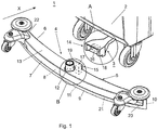
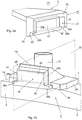
- the Fig. 1 . 2a and 2b show by way of example and not limitation, a first embodiment of the inventive stripper device 1 for a floor cleaning machine 2, in particular a scrubber-drier.
- the suction nozzle 4 is arranged in the direction of travel, ie in the forward movement direction X behind the scrub brushes (not shown) and mounted by means of a mounting plate designed as a mounting device 3 behind the machine and fixed to the floor cleaning machine 2 installed.
- the suction hose (not shown) is directly connected to the suction nozzle 12, which is located on the suction nozzle 4.
- the suction nozzle 4 may be mounted below the floor cleaning machine 2 and pivotally, for example via a suction nozzle arm ( 3 and 4 ) trained holding device 3, for example, on a brush housing (not shown) to be attached to the machine.
- the in the Fig. 1 . 2a and 2b illustrated first embodiment of the inventive scraper device 1 comprises a suction nozzle 4 which is transverse to the forward movement X of the floor cleaning machine 2 attached to the same and a rear scraper blade 9, a front scraper blade 10 and disposed between the rear and the front scraper blade 9, 10 open bottom suction channel 11 includes.
- the suction nozzle 4 further comprises an elongate frame 5 with a front side 6, a rear side 7, an upper side 13, a lower side 21 and a cavity 8 open at the bottom of the frame 5.
- a suction nozzle 12 is arranged on the frame 5, which - Scraper device 1 viewed in the vertical direction - is arranged on the upper side 13 of the frame 5 and opens into the suction channel 11.
- the scraper device 1 For releasable attachment of the suction nozzle 4 to the floor cleaning machine 2, the scraper device 1 comprises a holding device 3, which is fastened or fixed to the floor cleaning machine 2, and which comprises a first coupling part 14 which releasably engages with a second coupling part 15 arranged on the suction nozzle 4 can be brought.
- the first coupling part 14 comprises a first magnet 16, while the second coupling part 15 comprises a second magnet 17 or alternatively a ferromagnetic part, so that the first and second coupling part 14, 15 are pulled against each other in the assembled state of the scraper device 1.
- the first and second magnets 16, 17 each comprise a permanent magnet, which are arranged with respect to their polarity in the first, respectively second coupling part 14, 15 such that the suction nozzle 4 is pulled against the holding device 3 by the magnetic force.
- first and second magnets 16, 17 may comprise a permanent magnet or an electromagnet, and instead of the second magnet 17 may be a ferromagnetic part on the other coupling part 14, 15 be arranged, wherein in the case of an electromagnet, this is preferably arranged on the first coupling part 14, which is arranged in the present first embodiment of the holding device 3, so that the electromagnet can be supplied with electrical energy from the floor cleaning machine 2 and no separate source of energy is necessary ,
- the first and second magnets 16, 17 may each include a plurality of permanent magnets, for example 2 to 10 pieces.
- the first and second magnets 16, 17 may be formed as polyhedra (cubes, cuboids), for example with a quadrangular or rectangular cross-sectional area or as cylinders. Suitable magnetic materials are: neodymium magnets, hard ferrite magnets, AlNiCo magnets, SmCo magnets, plastic bonded magnets or steel.
- the breakaway force of the magnetic coupling formed by the first and second magnets 16, 17 is preferably between 1 N (Newton) to 1000 N (Newton).
- first coupling part 14 is formed as a female coupling structure 18 and the second coupling part 15 is formed as a complementary male coupling structure 19.
- the female and male coupling structures 18, 19 are releasably engageable with each other in the forward movement direction X and positively connectable with each other against the upper surface 13 of the suction nozzle 4 and transversely to the forward movement direction X.
- the coupling is stabilized in addition to the first and second magnets 16, 17 by positive locking, so that they only in a uncoupling rotational direction ( Fig. 4 ) is removable without great force. In all other directions, the coupling is more difficult to decouple.
- the elongated frame 5 of the suction nozzle 4 is divided by a median plane 20 in two each transverse to the direction of movement X extending halves.
- the arranged on the suction nozzle 4 male coupling structure 19 with the elevation 26 comprises a mounted on the top 13 of the frame 5 on the frame 5 plate 25, with a resting on the top 13 of the frame 5 bearing surface 24.
- the female coupling structure 18 arranged on the holding device 3 comprises a recess 27.
- the elevation 26 of the male coupling structure 19 projects perpendicularly to the front side 6 of the frame 5 via this In addition, so that the survey 26 perpendicular to the front side 6 of the frame 5 in the recess 27 can be inserted.
- the survey 26 is wedge-shaped, wherein the upper abutment surface 28 of the survey 26 against the resting on the top 13 of the frame 5 bearing surface 24 of the plate 25 and the first and second lateral abutment surface 29 a, 29 b of the survey 26 are bevelled against the median plane 20 , so that the elevation 26 tapers in the direction of the directed against the holding device 3 front 30 of the survey 26.
- the angle between the bevelled upper abutment surface and the upper side 13 of the frame 5 and between the first, respectively second lateral abutment surface 29a, 29b and the center plane 20 may be, for example and not restrictive, at least 5 °, preferably at least 15 °.
- the elevation 26 comprises, in the region of the bearing surface 24 of the plate 25, two shoulders 38a, 38b projecting laterally beyond the first and second side surfaces 29a, 29b.
- the depression 27 in the region of the underside 34 of the female coupling structure 18 comprises two lateral recesses 39a, 39b for receiving the shoulders 38a, 38b arranged on the elevation 26 in the coupled state of the suction nozzle 4.
- the recess 27 comprises an upper abutment surface 31 of the recess 27 bevelled against the underside 34 of the female coupling structure 18 and a first and second lateral abutment surface 32a, 32b of the recess 27, which are beveled against the median plane 20, so that against the recess 27 in the direction of directed against the suction nozzle 4 front 33 of the recess 27 expands. Furthermore, the underside 34 of the female coupling structure 18 merges with a rounding 40 into the rear side 41 of the recess 27 arranged away from the frame 5 of the suction nozzle 4.
- the rear side 41 of the recess 27 forms in the area of the underside 34 of the female coupling structure 18 for the flat front side 30 of the elevation 26 in the decoupling a transverse axis of rotation (line contact) to the central plane 20.
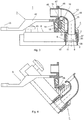
- the arrangement and design of the rounding 40 is selected such that by the position of the uncoupling rotation axis 48 (FIG. Fig. 4 ) In the first moment the smallest possible decoupling torque is needed. The further the suction nozzle 4 is turned off ( Fig. 4 ), the further shifts the decoupling axis of rotation 48 away from the magnets 16, 17 so as to create the largest possible gap between the two magnets 16, 17.
- the elevation 26 is held by means of frictional engagement in the recess 27, which is caused by the attraction of the first and second magnets 16, 17.
- the suction nozzle 4 is curved by way of example and not limitation in length between the first end 22 and the second end 23.
- front scraper blade 10 By arranged in the region of the front side 6 of the suction nozzle 4 front scraper blade 10 and arranged in the rear side 7 of the suction nozzle 4 rear scraper blade 9 is through the rear scraper blade 9, the front scraper blade 10 and the bottom 21 of the frame 5, the bottom open suction channel 11 formed.
- the frame 5 of the suction nozzle 4 may be formed in two parts by way of example and not by way of limitation ( 3 and 4 ), whereby a clamping of the rear and front scraper blades 9, 10 is made possible.
- the rear and front Abstreiferattention 9, 10 by means of screws or pins and / or bands outside the frame 5 or in the cavity 8 of the frame 5 may be attached.
- the in the 3 and 4 illustrated second embodiment of the inventive stripper 1 allows example and not limiting attachment of the suction nozzle 4 below the floor cleaning machine 2 and in the Vornchmonyscardi X behind the scrub brush (not shown), wherein the holding device 3 comprises a one-piece with the first coupling member 14 arm 42, which can be attached to a brush housing (not shown) of the floor cleaning machine 2 pivotally about a vertical axis of rotation 43 during operation of the floor cleaning machine 2.
- This second embodiment ( 3 and 4 ) differs from the first embodiment only in that the suction nozzle 12 comprises a curved against the front side 6 of the frame 5 pipe bend 44 and the first coupling part 14 comprises an outlet opening of the pipe bend 44 arranged in alignment pipe socket 45.
- an elastic sealing lip 46 for example made of rubber with a projection, while arranged on the first coupling part 14 pipe socket 45 at its counter to the Suction nozzle 4 directed free end comprises a flange 47 which is pressed in a coupled to the holding device 3 state of the suction nozzle 4 by the attraction of the first and second magnets 16, 17 against the sealing lip 46, so that in operation of the scraper device 1, a seal between the pipe bend 44 and the pipe socket 45 is made.
- This second embodiment allows a coupling of the arranged at the suction nozzle 4 suction nozzle 12 with the arranged on the holding device 3 pipe socket 45, which in turn is connected to the suction hose (not shown) of the floor cleaning machine 2, by magnetic force. Simultaneously with the connection or disconnection of the suction nozzle 4 to the holding device 3 thus the suction nozzle 4 is connected to the attached to the floor cleaning machine 2 suction hose or separated ..
- the frame 5 of the suction nozzle by way of example and not limitation, formed in two parts and includes an upper member 37 and a lower member 35.
- the upper member 37 is bounded above by the top 13 of the frame 5 and has a against the bottom 21 of Frame 5 open cavity, in which the lower member 35 is partially or completely inserted. In this cavity remains between the upper and the lower member 37, 35 in the region of the front side 6 of the frame 5 and in the region of the back 7 each over the entire length of the lower member 35 extending intermediate space in which the front, respectively the rear Scraper blade 9, 10 are clamped.
- the lower member 35 includes two side surfaces in the forward movement direction X, which at the bottom 21 of the suction nozzle 4 orthogonal to the forward movement direction X have a distance to each other, this distance is reduced against the top 13 of the suction nozzle 4 and the cavity in the upper member 37 also tapers against the top 13 of the suction nozzle 4, so that the Wiper blades 9, 10 are firmly fixed to the suction nozzle by wedging or hanging.
Landscapes
- Nozzles For Electric Vacuum Cleaners (AREA)
Priority Applications (4)
| Application Number | Priority Date | Filing Date | Title |
|---|---|---|---|
| PL17179773T PL3424397T3 (pl) | 2017-07-05 | 2017-07-05 | Moduł zgarniający maszyny do czyszczenia podłogi |
| DK17179773.1T DK3424397T3 (da) | 2017-07-05 | 2017-07-05 | Strippingindretning til en gulvrensemaskine |
| EP17179773.1A EP3424397B1 (de) | 2017-07-05 | 2017-07-05 | Abstreifervorrichtung für eine bodenreinigungsmaschine |
| CN201810732706.5A CN109199257A (zh) | 2017-07-05 | 2018-07-05 | 用于地板清洁机的刮擦装置 |
Applications Claiming Priority (1)
| Application Number | Priority Date | Filing Date | Title |
|---|---|---|---|
| EP17179773.1A EP3424397B1 (de) | 2017-07-05 | 2017-07-05 | Abstreifervorrichtung für eine bodenreinigungsmaschine |
Publications (2)
| Publication Number | Publication Date |
|---|---|
| EP3424397A1 EP3424397A1 (de) | 2019-01-09 |
| EP3424397B1 true EP3424397B1 (de) | 2019-11-27 |
Family
ID=59294991
Family Applications (1)
| Application Number | Title | Priority Date | Filing Date |
|---|---|---|---|
| EP17179773.1A Active EP3424397B1 (de) | 2017-07-05 | 2017-07-05 | Abstreifervorrichtung für eine bodenreinigungsmaschine |
Country Status (4)
| Country | Link |
|---|---|
| EP (1) | EP3424397B1 (pl) |
| CN (1) | CN109199257A (pl) |
| DK (1) | DK3424397T3 (pl) |
| PL (1) | PL3424397T3 (pl) |
Families Citing this family (4)
| Publication number | Priority date | Publication date | Assignee | Title |
|---|---|---|---|---|
| PL3754112T3 (pl) * | 2019-06-18 | 2023-10-02 | Marcel Boschung Ag | Pojazd ssący z odłączaną ssawką |
| WO2021113224A1 (en) * | 2019-12-02 | 2021-06-10 | Techtronic Cordless Gp | Floor cleaner having a removable nozzle |
| DE102022111607A1 (de) * | 2022-05-10 | 2023-11-16 | Hako Gmbh | Saugfußanordnung für eine Bodenreinigungsmaschine |
| CN115379097B (zh) * | 2022-08-24 | 2023-11-07 | 深圳禹航空间技术有限公司 | 一种基于永磁不定向同步电机与磁力耦合传动的雨刮装置 |
Family Cites Families (8)
| Publication number | Priority date | Publication date | Assignee | Title |
|---|---|---|---|---|
| DE502006005464D1 (de) * | 2006-10-19 | 2010-01-07 | Hako Gmbh | Bodenreinigungsmaschine mit einem verschwenkbaren Saugfuss |
| EP2011427A1 (en) | 2007-07-04 | 2009-01-07 | Comac S.p.A. | Floor wiper for floor cleansing and drying machines |
| CN101292853B (zh) * | 2008-05-09 | 2011-04-06 | 艾和金 | 一种驾驶式洗地机 |
| IT1391610B1 (it) * | 2008-11-05 | 2012-01-11 | Ip Cleaning S P A | Lavapavimenti |
| TWI460027B (zh) * | 2012-07-06 | 2014-11-11 | Uni Ring Tech Co Ltd | Quick release self-propelled apparatus cleaning method of cleaning mechanism |
| TW201605396A (zh) * | 2014-08-01 | 2016-02-16 | Uni Ring Tech Co Ltd | 清潔構件、裝置及其清潔方法 |
| CN204813713U (zh) * | 2015-07-01 | 2015-12-02 | 广东浩宇清洁环保设备有限公司 | 吸水扒改良结构 |
| CN105962860A (zh) * | 2016-07-17 | 2016-09-28 | 刘祥发 | 一种扫地刮水多用拖把 |
-
2017
- 2017-07-05 DK DK17179773.1T patent/DK3424397T3/da active
- 2017-07-05 PL PL17179773T patent/PL3424397T3/pl unknown
- 2017-07-05 EP EP17179773.1A patent/EP3424397B1/de active Active
-
2018
- 2018-07-05 CN CN201810732706.5A patent/CN109199257A/zh active Pending
Non-Patent Citations (1)
| Title |
|---|
| None * |
Also Published As
| Publication number | Publication date |
|---|---|
| DK3424397T3 (da) | 2020-03-02 |
| PL3424397T3 (pl) | 2020-05-18 |
| EP3424397A1 (de) | 2019-01-09 |
| CN109199257A (zh) | 2019-01-15 |
Similar Documents
| Publication | Publication Date | Title |
|---|---|---|
| EP3424397A1 (de) | Abstreifervorrichtung für eine bodenreinigungsmaschine | |
| DE102007018467A1 (de) | Motorisch angetriebene Werkzeugmaschine | |
| DE602005004317T2 (de) | Befestigungseinrichtung für elektrische Steckverbinder und Verwendung derselben | |
| DE2550790A1 (de) | Abstreifeinrichtung fuer gleitbahnen an werkzeugmaschinen | |
| EP3393320B1 (de) | Saugdüse für ein hartflächenreinigungsgerät und hartflächenreinigungsgerät mit einer derartigen saugdüse | |
| EP3491988B1 (de) | Klick-düse | |
| DE3136401C2 (de) | Mehrzweck-Reinigungsgerät | |
| DE102014117418A1 (de) | Bodendüse für ein Bodenpflegegerät und Verfahren zum Herstellen einer Bodendüse für ein Bodenpflegegerät | |
| WO2019219582A1 (de) | Nassreinigungsvorrichtung zur nassreinigung einer bodenfläche | |
| DE2553061C2 (pl) | ||
| DE4136707A1 (de) | Verfahren und vorrichtung zum herausloesen eines metallsteckverbindungsteils | |
| DE102013204394A1 (de) | Bodenreinigungsmaschine mit einer Kupplungsvorrichtung für ein Anbauteil | |
| CH716750A2 (de) | Schildhalterung zur Befestigung eines Schildes. | |
| DE3246887A1 (de) | Stielbefestigungskupplung, insbesondere fuer haus- und gartengeraete | |
| EP3603899A1 (de) | Schnittstelle für akkupack | |
| DE2701350A1 (de) | Verbindervorrichtung | |
| EP3006636B1 (de) | Wandablauf mit Pumpe | |
| EP4275569B1 (de) | Saugfussanordnung für eine bodenreinigungsmaschine | |
| EP3274513B1 (de) | Bodenreinigungsmaschine | |
| EP0019833B1 (de) | Lösbare Stielbefestigung für Besen oder Schrubber | |
| EP3274511A1 (de) | Kehrmaschine | |
| EP3185743B1 (de) | Saugdüse und hartflächenabsauggerät | |
| DE102015109778B3 (de) | Schrubbdeck für eine Bodenreinigungsmaschine | |
| DE102024124229A1 (de) | Sauggerät mit einem Steckverbindereinsatz | |
| EP3758568B1 (de) | Saugdüse und tragbares hartflächenabsauggerät |
Legal Events
| Date | Code | Title | Description |
|---|---|---|---|
| PUAI | Public reference made under article 153(3) epc to a published international application that has entered the european phase |
Free format text: ORIGINAL CODE: 0009012 |
|
| STAA | Information on the status of an ep patent application or granted ep patent |
Free format text: STATUS: REQUEST FOR EXAMINATION WAS MADE |
|
| 17P | Request for examination filed |
Effective date: 20170705 |
|
| AK | Designated contracting states |
Kind code of ref document: A1 Designated state(s): AL AT BE BG CH CY CZ DE DK EE ES FI FR GB GR HR HU IE IS IT LI LT LU LV MC MK MT NL NO PL PT RO RS SE SI SK SM TR |
|
| AX | Request for extension of the european patent |
Extension state: BA ME |
|
| GRAP | Despatch of communication of intention to grant a patent |
Free format text: ORIGINAL CODE: EPIDOSNIGR1 |
|
| STAA | Information on the status of an ep patent application or granted ep patent |
Free format text: STATUS: GRANT OF PATENT IS INTENDED |
|
| RIC1 | Information provided on ipc code assigned before grant |
Ipc: A47L 13/11 20060101ALI20190627BHEP Ipc: A47L 11/30 20060101AFI20190627BHEP Ipc: A47L 11/40 20060101ALI20190627BHEP |
|
| INTG | Intention to grant announced |
Effective date: 20190723 |
|
| GRAS | Grant fee paid |
Free format text: ORIGINAL CODE: EPIDOSNIGR3 |
|
| GRAA | (expected) grant |
Free format text: ORIGINAL CODE: 0009210 |
|
| STAA | Information on the status of an ep patent application or granted ep patent |
Free format text: STATUS: THE PATENT HAS BEEN GRANTED |
|
| AK | Designated contracting states |
Kind code of ref document: B1 Designated state(s): AL AT BE BG CH CY CZ DE DK EE ES FI FR GB GR HR HU IE IS IT LI LT LU LV MC MK MT NL NO PL PT RO RS SE SI SK SM TR |
|
| REG | Reference to a national code |
Ref country code: GB Ref legal event code: FG4D Free format text: NOT ENGLISH |
|
| REG | Reference to a national code |
Ref country code: CH Ref legal event code: EP |
|
| REG | Reference to a national code |
Ref country code: AT Ref legal event code: REF Ref document number: 1205780 Country of ref document: AT Kind code of ref document: T Effective date: 20191215 |
|
| REG | Reference to a national code |
Ref country code: DE Ref legal event code: R096 Ref document number: 502017002974 Country of ref document: DE |
|
| REG | Reference to a national code |
Ref country code: IE Ref legal event code: FG4D Free format text: LANGUAGE OF EP DOCUMENT: GERMAN |
|
| REG | Reference to a national code |
Ref country code: CH Ref legal event code: NV Representative=s name: DR. LUSUARDI AG, CH |
|
| REG | Reference to a national code |
Ref country code: DK Ref legal event code: T3 Effective date: 20200226 |
|
| REG | Reference to a national code |
Ref country code: SE Ref legal event code: TRGR |
|
| REG | Reference to a national code |
Ref country code: LT Ref legal event code: MG4D |
|
| PG25 | Lapsed in a contracting state [announced via postgrant information from national office to epo] |
Ref country code: BG Free format text: LAPSE BECAUSE OF FAILURE TO SUBMIT A TRANSLATION OF THE DESCRIPTION OR TO PAY THE FEE WITHIN THE PRESCRIBED TIME-LIMIT Effective date: 20200227 Ref country code: FI Free format text: LAPSE BECAUSE OF FAILURE TO SUBMIT A TRANSLATION OF THE DESCRIPTION OR TO PAY THE FEE WITHIN THE PRESCRIBED TIME-LIMIT Effective date: 20191127 Ref country code: GR Free format text: LAPSE BECAUSE OF FAILURE TO SUBMIT A TRANSLATION OF THE DESCRIPTION OR TO PAY THE FEE WITHIN THE PRESCRIBED TIME-LIMIT Effective date: 20200228 Ref country code: NO Free format text: LAPSE BECAUSE OF FAILURE TO SUBMIT A TRANSLATION OF THE DESCRIPTION OR TO PAY THE FEE WITHIN THE PRESCRIBED TIME-LIMIT Effective date: 20200227 Ref country code: LT Free format text: LAPSE BECAUSE OF FAILURE TO SUBMIT A TRANSLATION OF THE DESCRIPTION OR TO PAY THE FEE WITHIN THE PRESCRIBED TIME-LIMIT Effective date: 20191127 Ref country code: LV Free format text: LAPSE BECAUSE OF FAILURE TO SUBMIT A TRANSLATION OF THE DESCRIPTION OR TO PAY THE FEE WITHIN THE PRESCRIBED TIME-LIMIT Effective date: 20191127 |
|
| REG | Reference to a national code |
Ref country code: NL Ref legal event code: FP |
|
| PG25 | Lapsed in a contracting state [announced via postgrant information from national office to epo] |
Ref country code: IS Free format text: LAPSE BECAUSE OF FAILURE TO SUBMIT A TRANSLATION OF THE DESCRIPTION OR TO PAY THE FEE WITHIN THE PRESCRIBED TIME-LIMIT Effective date: 20200327 Ref country code: RS Free format text: LAPSE BECAUSE OF FAILURE TO SUBMIT A TRANSLATION OF THE DESCRIPTION OR TO PAY THE FEE WITHIN THE PRESCRIBED TIME-LIMIT Effective date: 20191127 Ref country code: HR Free format text: LAPSE BECAUSE OF FAILURE TO SUBMIT A TRANSLATION OF THE DESCRIPTION OR TO PAY THE FEE WITHIN THE PRESCRIBED TIME-LIMIT Effective date: 20191127 |
|
| PG25 | Lapsed in a contracting state [announced via postgrant information from national office to epo] |
Ref country code: AL Free format text: LAPSE BECAUSE OF FAILURE TO SUBMIT A TRANSLATION OF THE DESCRIPTION OR TO PAY THE FEE WITHIN THE PRESCRIBED TIME-LIMIT Effective date: 20191127 |
|
| PG25 | Lapsed in a contracting state [announced via postgrant information from national office to epo] |
Ref country code: ES Free format text: LAPSE BECAUSE OF FAILURE TO SUBMIT A TRANSLATION OF THE DESCRIPTION OR TO PAY THE FEE WITHIN THE PRESCRIBED TIME-LIMIT Effective date: 20191127 Ref country code: PT Free format text: LAPSE BECAUSE OF FAILURE TO SUBMIT A TRANSLATION OF THE DESCRIPTION OR TO PAY THE FEE WITHIN THE PRESCRIBED TIME-LIMIT Effective date: 20200419 Ref country code: EE Free format text: LAPSE BECAUSE OF FAILURE TO SUBMIT A TRANSLATION OF THE DESCRIPTION OR TO PAY THE FEE WITHIN THE PRESCRIBED TIME-LIMIT Effective date: 20191127 Ref country code: CZ Free format text: LAPSE BECAUSE OF FAILURE TO SUBMIT A TRANSLATION OF THE DESCRIPTION OR TO PAY THE FEE WITHIN THE PRESCRIBED TIME-LIMIT Effective date: 20191127 Ref country code: RO Free format text: LAPSE BECAUSE OF FAILURE TO SUBMIT A TRANSLATION OF THE DESCRIPTION OR TO PAY THE FEE WITHIN THE PRESCRIBED TIME-LIMIT Effective date: 20191127 |
|
| REG | Reference to a national code |
Ref country code: DE Ref legal event code: R097 Ref document number: 502017002974 Country of ref document: DE |
|
| PG25 | Lapsed in a contracting state [announced via postgrant information from national office to epo] |
Ref country code: SM Free format text: LAPSE BECAUSE OF FAILURE TO SUBMIT A TRANSLATION OF THE DESCRIPTION OR TO PAY THE FEE WITHIN THE PRESCRIBED TIME-LIMIT Effective date: 20191127 Ref country code: SK Free format text: LAPSE BECAUSE OF FAILURE TO SUBMIT A TRANSLATION OF THE DESCRIPTION OR TO PAY THE FEE WITHIN THE PRESCRIBED TIME-LIMIT Effective date: 20191127 |
|
| PLBE | No opposition filed within time limit |
Free format text: ORIGINAL CODE: 0009261 |
|
| STAA | Information on the status of an ep patent application or granted ep patent |
Free format text: STATUS: NO OPPOSITION FILED WITHIN TIME LIMIT |
|
| 26N | No opposition filed |
Effective date: 20200828 |
|
| PG25 | Lapsed in a contracting state [announced via postgrant information from national office to epo] |
Ref country code: SI Free format text: LAPSE BECAUSE OF FAILURE TO SUBMIT A TRANSLATION OF THE DESCRIPTION OR TO PAY THE FEE WITHIN THE PRESCRIBED TIME-LIMIT Effective date: 20191127 |
|
| PG25 | Lapsed in a contracting state [announced via postgrant information from national office to epo] |
Ref country code: MC Free format text: LAPSE BECAUSE OF FAILURE TO SUBMIT A TRANSLATION OF THE DESCRIPTION OR TO PAY THE FEE WITHIN THE PRESCRIBED TIME-LIMIT Effective date: 20191127 |
|
| PG25 | Lapsed in a contracting state [announced via postgrant information from national office to epo] |
Ref country code: FR Free format text: LAPSE BECAUSE OF NON-PAYMENT OF DUE FEES Effective date: 20200731 Ref country code: IE Free format text: LAPSE BECAUSE OF NON-PAYMENT OF DUE FEES Effective date: 20200705 |
|
| GBPC | Gb: european patent ceased through non-payment of renewal fee |
Effective date: 20210705 |
|
| PG25 | Lapsed in a contracting state [announced via postgrant information from national office to epo] |
Ref country code: GB Free format text: LAPSE BECAUSE OF NON-PAYMENT OF DUE FEES Effective date: 20210705 |
|
| PG25 | Lapsed in a contracting state [announced via postgrant information from national office to epo] |
Ref country code: TR Free format text: LAPSE BECAUSE OF FAILURE TO SUBMIT A TRANSLATION OF THE DESCRIPTION OR TO PAY THE FEE WITHIN THE PRESCRIBED TIME-LIMIT Effective date: 20191127 Ref country code: MT Free format text: LAPSE BECAUSE OF FAILURE TO SUBMIT A TRANSLATION OF THE DESCRIPTION OR TO PAY THE FEE WITHIN THE PRESCRIBED TIME-LIMIT Effective date: 20191127 Ref country code: CY Free format text: LAPSE BECAUSE OF FAILURE TO SUBMIT A TRANSLATION OF THE DESCRIPTION OR TO PAY THE FEE WITHIN THE PRESCRIBED TIME-LIMIT Effective date: 20191127 |
|
| PG25 | Lapsed in a contracting state [announced via postgrant information from national office to epo] |
Ref country code: MK Free format text: LAPSE BECAUSE OF FAILURE TO SUBMIT A TRANSLATION OF THE DESCRIPTION OR TO PAY THE FEE WITHIN THE PRESCRIBED TIME-LIMIT Effective date: 20191127 |
|
| P01 | Opt-out of the competence of the unified patent court (upc) registered |
Effective date: 20230627 |
|
| PGFP | Annual fee paid to national office [announced via postgrant information from national office to epo] |
Ref country code: LU Payment date: 20240719 Year of fee payment: 8 |
|
| PGFP | Annual fee paid to national office [announced via postgrant information from national office to epo] |
Ref country code: BE Payment date: 20240719 Year of fee payment: 8 |
|
| PGFP | Annual fee paid to national office [announced via postgrant information from national office to epo] |
Ref country code: NL Payment date: 20250721 Year of fee payment: 9 |
|
| PGFP | Annual fee paid to national office [announced via postgrant information from national office to epo] |
Ref country code: DK Payment date: 20250725 Year of fee payment: 9 Ref country code: DE Payment date: 20250722 Year of fee payment: 9 |
|
| PGFP | Annual fee paid to national office [announced via postgrant information from national office to epo] |
Ref country code: IT Payment date: 20250724 Year of fee payment: 9 |
|
| PGFP | Annual fee paid to national office [announced via postgrant information from national office to epo] |
Ref country code: AT Payment date: 20250722 Year of fee payment: 9 |
|
| PGFP | Annual fee paid to national office [announced via postgrant information from national office to epo] |
Ref country code: SE Payment date: 20250722 Year of fee payment: 9 Ref country code: CH Payment date: 20250801 Year of fee payment: 9 |
|
| PG25 | Lapsed in a contracting state [announced via postgrant information from national office to epo] |
Ref country code: LU Free format text: LAPSE BECAUSE OF NON-PAYMENT OF DUE FEES Effective date: 20250705 |
|
| REG | Reference to a national code |
Ref country code: BE Ref legal event code: MM Effective date: 20250731 |
|
| PG25 | Lapsed in a contracting state [announced via postgrant information from national office to epo] |
Ref country code: BE Free format text: LAPSE BECAUSE OF NON-PAYMENT OF DUE FEES Effective date: 20250731 |
|
| PGFP | Annual fee paid to national office [announced via postgrant information from national office to epo] |
Ref country code: PL Payment date: 20260622 Year of fee payment: 10 |
|
| REG | Reference to a national code |
Ref country code: CH Ref legal event code: U11 Free format text: ST27 STATUS EVENT CODE: U-0-0-U10-U11 (AS PROVIDED BY THE NATIONAL OFFICE) Effective date: 20260801 |