EP3424397B1 - Stripping device for a floor cleaning machine - Google Patents
Stripping device for a floor cleaning machine Download PDFInfo
- Publication number
- EP3424397B1 EP3424397B1 EP17179773.1A EP17179773A EP3424397B1 EP 3424397 B1 EP3424397 B1 EP 3424397B1 EP 17179773 A EP17179773 A EP 17179773A EP 3424397 B1 EP3424397 B1 EP 3424397B1
- Authority
- EP
- European Patent Office
- Prior art keywords
- suction nozzle
- stripping device
- frame
- coupling structure
- floor cleaning
- Prior art date
- Legal status (The legal status is an assumption and is not a legal conclusion. Google has not performed a legal analysis and makes no representation as to the accuracy of the status listed.)
- Active
Links
- 238000004140 cleaning Methods 0.000 title claims description 35
- 230000008878 coupling Effects 0.000 claims description 72
- 238000010168 coupling process Methods 0.000 claims description 72
- 238000005859 coupling reaction Methods 0.000 claims description 72
- 238000000034 method Methods 0.000 claims description 7
- 238000007789 sealing Methods 0.000 claims description 6
- 230000000295 complement effect Effects 0.000 claims description 4
- 230000005294 ferromagnetic effect Effects 0.000 claims description 3
- 239000011796 hollow space material Substances 0.000 claims 4
- 230000007704 transition Effects 0.000 claims 1
- 230000005291 magnetic effect Effects 0.000 description 6
- 230000006378 damage Effects 0.000 description 5
- 239000000203 mixture Substances 0.000 description 3
- 238000005201 scrubbing Methods 0.000 description 3
- 239000003599 detergent Substances 0.000 description 2
- 230000036961 partial effect Effects 0.000 description 2
- 230000000284 resting effect Effects 0.000 description 2
- 210000002023 somite Anatomy 0.000 description 2
- 241001136792 Alle Species 0.000 description 1
- 241001295925 Gegenes Species 0.000 description 1
- 229910001047 Hard ferrite Inorganic materials 0.000 description 1
- 229910000831 Steel Inorganic materials 0.000 description 1
- 208000012886 Vertigo Diseases 0.000 description 1
- 208000027418 Wounds and injury Diseases 0.000 description 1
- 229910000828 alnico Inorganic materials 0.000 description 1
- 239000012459 cleaning agent Substances 0.000 description 1
- 238000011161 development Methods 0.000 description 1
- 230000018109 developmental process Effects 0.000 description 1
- 238000001035 drying Methods 0.000 description 1
- 238000000605 extraction Methods 0.000 description 1
- 208000014674 injury Diseases 0.000 description 1
- 238000003780 insertion Methods 0.000 description 1
- 230000037431 insertion Effects 0.000 description 1
- 239000002655 kraft paper Substances 0.000 description 1
- 230000000670 limiting effect Effects 0.000 description 1
- 239000000696 magnetic material Substances 0.000 description 1
- 239000000463 material Substances 0.000 description 1
- 229910001172 neodymium magnet Inorganic materials 0.000 description 1
- 230000000149 penetrating effect Effects 0.000 description 1
- 230000002829 reductive effect Effects 0.000 description 1
- 230000002441 reversible effect Effects 0.000 description 1
- 229910000938 samarium–cobalt magnet Inorganic materials 0.000 description 1
- 239000010959 steel Substances 0.000 description 1
Images
Classifications
-
- A—HUMAN NECESSITIES
- A47—FURNITURE; DOMESTIC ARTICLES OR APPLIANCES; COFFEE MILLS; SPICE MILLS; SUCTION CLEANERS IN GENERAL
- A47L—DOMESTIC WASHING OR CLEANING; SUCTION CLEANERS IN GENERAL
- A47L11/00—Machines for cleaning floors, carpets, furniture, walls, or wall coverings
- A47L11/29—Floor-scrubbing machines characterised by means for taking-up dirty liquid
- A47L11/30—Floor-scrubbing machines characterised by means for taking-up dirty liquid by suction
-
- A—HUMAN NECESSITIES
- A47—FURNITURE; DOMESTIC ARTICLES OR APPLIANCES; COFFEE MILLS; SPICE MILLS; SUCTION CLEANERS IN GENERAL
- A47L—DOMESTIC WASHING OR CLEANING; SUCTION CLEANERS IN GENERAL
- A47L11/00—Machines for cleaning floors, carpets, furniture, walls, or wall coverings
- A47L11/28—Floor-scrubbing machines, motor-driven
-
- A—HUMAN NECESSITIES
- A47—FURNITURE; DOMESTIC ARTICLES OR APPLIANCES; COFFEE MILLS; SPICE MILLS; SUCTION CLEANERS IN GENERAL
- A47L—DOMESTIC WASHING OR CLEANING; SUCTION CLEANERS IN GENERAL
- A47L11/00—Machines for cleaning floors, carpets, furniture, walls, or wall coverings
- A47L11/40—Parts or details of machines not provided for in groups A47L11/02 - A47L11/38, or not restricted to one of these groups, e.g. handles, arrangements of switches, skirts, buffers, levers
- A47L11/4036—Parts or details of the surface treating tools
- A47L11/4044—Vacuuming or pick-up tools; Squeegees
-
- A—HUMAN NECESSITIES
- A47—FURNITURE; DOMESTIC ARTICLES OR APPLIANCES; COFFEE MILLS; SPICE MILLS; SUCTION CLEANERS IN GENERAL
- A47L—DOMESTIC WASHING OR CLEANING; SUCTION CLEANERS IN GENERAL
- A47L13/00—Implements for cleaning floors, carpets, furniture, walls, or wall coverings
- A47L13/10—Scrubbing; Scouring; Cleaning; Polishing
- A47L13/11—Squeegees
Definitions
- the invention relates to a scraper device for a floor cleaning machine according to the preamble of claim 1 and to a method for disassembling the suction nozzle of a floor cleaning machine according to the preamble of patent claim 14.
- a water-cleaning agent mixture for the scrubbing process is applied to the floor for cleaning floors.
- This water-detergent mixture which absorbs the dirt by the scrubbing process, must then be removed together with the dirt again from the ground.
- Such scrubber driers therefore typically include a number of scrubbers, e.g. Brushes, which are arranged on a front part of the machine, and arranged on the rear part of the machine suction nozzle, by means of which the dirt-containing water-detergent mixture is sucked from the ground. At the suction nozzle scraper blades are arranged, which wear out and therefore must be replaced frequently.
- the suction nozzle is usually attached to the scrubber, so that it can be removed and cleaned or maintained with little effort. This means that this coupling between the machine and the suction nozzle is essential for the daily handling of the user.
- the suction nozzle is provided with fasteners, e.g. Screws, clamps or star handles on the floor cleaning machine releasably secured while the scrapers are in turn releasably secured via different clamping methods on the frame of the suction nozzle.
- the suction nozzle is located in the direction of travel behind the scrub brushes and can be mounted below or behind the machine. It is usually pivotable via e.g. a Saugdüsenarm attached to the machine, but can also be installed fixed to the scrubber. An attached to a floor cleaning machine suction hose is connected directly to the nozzle, which is located on the suction nozzle.
- the suction nozzle In order to ensure a perfect suction performance, the suction nozzle must be able to be cleaned after use or in the event of streaking of any adhering soiling. If the extraction result is insufficient, it may be necessary to replace the worn scraper blades. To accomplish this, the suction nozzle must be removed awkward by loosening the two or more fastening screws and removing the suction hose. Since this is often not done due to the rather difficult accessibility and the time factor, the user may not be satisfied with the suction result.
- a scraper device for floor cleaning and drying machines is from the document EP 2 011 427 A1 [Crivellaro ] known.
- This known scraper device comprises a brush, which consists of a strip of elastically yielding material and is connected to a support element.
- This support element comprises a suction nozzle and is by means of a snap-in quick coupling to a connected to the chassis of the machine support structure and uncoupled.
- the quick coupling comprises two arranged on the support structure engaging elements, which automatically engage in the assembly of the brush to the support structure by means of spring force of a spring arranged in the brush pins.
- the uncoupling of the brush from the support structure is done manually by pressing on the lugs arranged on the engagement elements.
- a disadvantage of this known scraper device is in particular an insufficient protection of the machine against mechanical damage, eg by hooking the suction nozzle to obstacles, such as door jambs.
- the pins on the suction nozzle can be torn out of the engagement elements only in a forward direction of movement of the machine.
- the invention aims to remedy this situation.
- the invention has for its object to provide a scraper device for a floor cleaning machine, the connection between the suction nozzle and machine is designed such that an assembly, respectively disassembly is easy, fast and without great effort executable and at the same time a mechanical protection of the machine from mechanical damage Forwards and backwards and guaranteed when turning off the machine.
- the invention solves the stated object with a scraper device for a floor cleaning machine, which has the features of claim 1, and with a method for disassembling a suction nozzle of a floor cleaning machine having the features of claim 14.
- the female coupling structure is formed as a recess and includes a rounding, which passes from a bottom of the female coupling structure in a remote from the frame of the suction nozzle back of the recess.
- This embodiment allows the advantage that due to the rounding, the rear side of the recess in the region of the underside of the female coupling structure for the flat front of the survey in the decoupling forms a transverse axis of rotation (line contact) to the central plane.
- the suction nozzle comprises a curved against the front side of the frame pipe bend and the first coupling part comprises an aligned to an outlet opening of the pipe bend pipe socket.
- an elastic sealing lip with a projection or a flange with an annular seal is arranged at a free end of the pipe bend.
- the male coupling structure comprises a wedge-like projection with respect to the forward movement direction X and the female coupling structure comprises a complementarily formed recess.
- the elevation comprises an upper abutment surface and a first and a second lateral abutment surface, wherein the upper abutment surface is chamfered against the upper side of the frame, and the first and second lateral abutment surfaces are chamfered against a center plane of the suction nozzle, so that the elevation tapers in one direction against the holding device.
- the elevation comprises two shoulders projecting laterally beyond the first and second side surfaces, and the recess comprises two lateral recesses for receiving the shoulders arranged on the elevation in the coupled state of the suction nozzle.
- first and second magnets each comprise one or more permanent magnets.
- one of the first and second magnets includes an electromagnet.
- the tearing force between the first and second magnets is at least 0.5 N, preferably at least 1 N.
- the tearing force between the first and second magnets is at most 1,500 N, preferably at most 1,000 N.
- the suction nozzle comprises a rear scraper blade, which delimits the cavity in the region of the back, and a front scraper blade, which delimits the cavity in the region of the front side, so that a suction channel open at the bottom is formed.
- the method comprises the additional step of separating the suction nozzle from a suction hose attached to a floor cleaning machine.
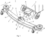
- the Fig. 1 . 2a and 2b show by way of example and not limitation, a first embodiment of the inventive stripper device 1 for a floor cleaning machine 2, in particular a scrubber-drier.
- the suction nozzle 4 is arranged in the direction of travel, ie in the forward movement direction X behind the scrub brushes (not shown) and mounted by means of a mounting plate designed as a mounting device 3 behind the machine and fixed to the floor cleaning machine 2 installed.
- the suction hose (not shown) is directly connected to the suction nozzle 12, which is located on the suction nozzle 4.
- the suction nozzle 4 may be mounted below the floor cleaning machine 2 and pivotally, for example via a suction nozzle arm ( 3 and 4 ) trained holding device 3, for example, on a brush housing (not shown) to be attached to the machine.
- the in the Fig. 1 . 2a and 2b illustrated first embodiment of the inventive scraper device 1 comprises a suction nozzle 4 which is transverse to the forward movement X of the floor cleaning machine 2 attached to the same and a rear scraper blade 9, a front scraper blade 10 and disposed between the rear and the front scraper blade 9, 10 open bottom suction channel 11 includes.
- the suction nozzle 4 further comprises an elongate frame 5 with a front side 6, a rear side 7, an upper side 13, a lower side 21 and a cavity 8 open at the bottom of the frame 5.
- a suction nozzle 12 is arranged on the frame 5, which - Scraper device 1 viewed in the vertical direction - is arranged on the upper side 13 of the frame 5 and opens into the suction channel 11.
- the scraper device 1 For releasable attachment of the suction nozzle 4 to the floor cleaning machine 2, the scraper device 1 comprises a holding device 3, which is fastened or fixed to the floor cleaning machine 2, and which comprises a first coupling part 14 which releasably engages with a second coupling part 15 arranged on the suction nozzle 4 can be brought.
- the first coupling part 14 comprises a first magnet 16, while the second coupling part 15 comprises a second magnet 17 or alternatively a ferromagnetic part, so that the first and second coupling part 14, 15 are pulled against each other in the assembled state of the scraper device 1.
- the first and second magnets 16, 17 each comprise a permanent magnet, which are arranged with respect to their polarity in the first, respectively second coupling part 14, 15 such that the suction nozzle 4 is pulled against the holding device 3 by the magnetic force.
- first and second magnets 16, 17 may comprise a permanent magnet or an electromagnet, and instead of the second magnet 17 may be a ferromagnetic part on the other coupling part 14, 15 be arranged, wherein in the case of an electromagnet, this is preferably arranged on the first coupling part 14, which is arranged in the present first embodiment of the holding device 3, so that the electromagnet can be supplied with electrical energy from the floor cleaning machine 2 and no separate source of energy is necessary ,
- the first and second magnets 16, 17 may each include a plurality of permanent magnets, for example 2 to 10 pieces.
- the first and second magnets 16, 17 may be formed as polyhedra (cubes, cuboids), for example with a quadrangular or rectangular cross-sectional area or as cylinders. Suitable magnetic materials are: neodymium magnets, hard ferrite magnets, AlNiCo magnets, SmCo magnets, plastic bonded magnets or steel.
- the breakaway force of the magnetic coupling formed by the first and second magnets 16, 17 is preferably between 1 N (Newton) to 1000 N (Newton).
- first coupling part 14 is formed as a female coupling structure 18 and the second coupling part 15 is formed as a complementary male coupling structure 19.
- the female and male coupling structures 18, 19 are releasably engageable with each other in the forward movement direction X and positively connectable with each other against the upper surface 13 of the suction nozzle 4 and transversely to the forward movement direction X.
- the coupling is stabilized in addition to the first and second magnets 16, 17 by positive locking, so that they only in a uncoupling rotational direction ( Fig. 4 ) is removable without great force. In all other directions, the coupling is more difficult to decouple.
- the elongated frame 5 of the suction nozzle 4 is divided by a median plane 20 in two each transverse to the direction of movement X extending halves.
- the arranged on the suction nozzle 4 male coupling structure 19 with the elevation 26 comprises a mounted on the top 13 of the frame 5 on the frame 5 plate 25, with a resting on the top 13 of the frame 5 bearing surface 24.
- the female coupling structure 18 arranged on the holding device 3 comprises a recess 27.
- the elevation 26 of the male coupling structure 19 projects perpendicularly to the front side 6 of the frame 5 via this In addition, so that the survey 26 perpendicular to the front side 6 of the frame 5 in the recess 27 can be inserted.
- the survey 26 is wedge-shaped, wherein the upper abutment surface 28 of the survey 26 against the resting on the top 13 of the frame 5 bearing surface 24 of the plate 25 and the first and second lateral abutment surface 29 a, 29 b of the survey 26 are bevelled against the median plane 20 , so that the elevation 26 tapers in the direction of the directed against the holding device 3 front 30 of the survey 26.
- the angle between the bevelled upper abutment surface and the upper side 13 of the frame 5 and between the first, respectively second lateral abutment surface 29a, 29b and the center plane 20 may be, for example and not restrictive, at least 5 °, preferably at least 15 °.
- the elevation 26 comprises, in the region of the bearing surface 24 of the plate 25, two shoulders 38a, 38b projecting laterally beyond the first and second side surfaces 29a, 29b.
- the depression 27 in the region of the underside 34 of the female coupling structure 18 comprises two lateral recesses 39a, 39b for receiving the shoulders 38a, 38b arranged on the elevation 26 in the coupled state of the suction nozzle 4.
- the recess 27 comprises an upper abutment surface 31 of the recess 27 bevelled against the underside 34 of the female coupling structure 18 and a first and second lateral abutment surface 32a, 32b of the recess 27, which are beveled against the median plane 20, so that against the recess 27 in the direction of directed against the suction nozzle 4 front 33 of the recess 27 expands. Furthermore, the underside 34 of the female coupling structure 18 merges with a rounding 40 into the rear side 41 of the recess 27 arranged away from the frame 5 of the suction nozzle 4.
- the rear side 41 of the recess 27 forms in the area of the underside 34 of the female coupling structure 18 for the flat front side 30 of the elevation 26 in the decoupling a transverse axis of rotation (line contact) to the central plane 20.
- the arrangement and design of the rounding 40 is selected such that by the position of the uncoupling rotation axis 48 (FIG. Fig. 4 ) In the first moment the smallest possible decoupling torque is needed. The further the suction nozzle 4 is turned off ( Fig. 4 ), the further shifts the decoupling axis of rotation 48 away from the magnets 16, 17 so as to create the largest possible gap between the two magnets 16, 17.
- the elevation 26 is held by means of frictional engagement in the recess 27, which is caused by the attraction of the first and second magnets 16, 17.
- the suction nozzle 4 is curved by way of example and not limitation in length between the first end 22 and the second end 23.
- front scraper blade 10 By arranged in the region of the front side 6 of the suction nozzle 4 front scraper blade 10 and arranged in the rear side 7 of the suction nozzle 4 rear scraper blade 9 is through the rear scraper blade 9, the front scraper blade 10 and the bottom 21 of the frame 5, the bottom open suction channel 11 formed.
- the frame 5 of the suction nozzle 4 may be formed in two parts by way of example and not by way of limitation ( 3 and 4 ), whereby a clamping of the rear and front scraper blades 9, 10 is made possible.
- the rear and front Abstreiferattention 9, 10 by means of screws or pins and / or bands outside the frame 5 or in the cavity 8 of the frame 5 may be attached.
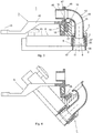
- the in the 3 and 4 illustrated second embodiment of the inventive stripper 1 allows example and not limiting attachment of the suction nozzle 4 below the floor cleaning machine 2 and in the Vornchmonyscardi X behind the scrub brush (not shown), wherein the holding device 3 comprises a one-piece with the first coupling member 14 arm 42, which can be attached to a brush housing (not shown) of the floor cleaning machine 2 pivotally about a vertical axis of rotation 43 during operation of the floor cleaning machine 2.
- This second embodiment ( 3 and 4 ) differs from the first embodiment only in that the suction nozzle 12 comprises a curved against the front side 6 of the frame 5 pipe bend 44 and the first coupling part 14 comprises an outlet opening of the pipe bend 44 arranged in alignment pipe socket 45.
- an elastic sealing lip 46 for example made of rubber with a projection, while arranged on the first coupling part 14 pipe socket 45 at its counter to the Suction nozzle 4 directed free end comprises a flange 47 which is pressed in a coupled to the holding device 3 state of the suction nozzle 4 by the attraction of the first and second magnets 16, 17 against the sealing lip 46, so that in operation of the scraper device 1, a seal between the pipe bend 44 and the pipe socket 45 is made.
- This second embodiment allows a coupling of the arranged at the suction nozzle 4 suction nozzle 12 with the arranged on the holding device 3 pipe socket 45, which in turn is connected to the suction hose (not shown) of the floor cleaning machine 2, by magnetic force. Simultaneously with the connection or disconnection of the suction nozzle 4 to the holding device 3 thus the suction nozzle 4 is connected to the attached to the floor cleaning machine 2 suction hose or separated ..
- the frame 5 of the suction nozzle by way of example and not limitation, formed in two parts and includes an upper member 37 and a lower member 35.
- the upper member 37 is bounded above by the top 13 of the frame 5 and has a against the bottom 21 of Frame 5 open cavity, in which the lower member 35 is partially or completely inserted. In this cavity remains between the upper and the lower member 37, 35 in the region of the front side 6 of the frame 5 and in the region of the back 7 each over the entire length of the lower member 35 extending intermediate space in which the front, respectively the rear Scraper blade 9, 10 are clamped.
- the lower member 35 includes two side surfaces in the forward movement direction X, which at the bottom 21 of the suction nozzle 4 orthogonal to the forward movement direction X have a distance to each other, this distance is reduced against the top 13 of the suction nozzle 4 and the cavity in the upper member 37 also tapers against the top 13 of the suction nozzle 4, so that the Wiper blades 9, 10 are firmly fixed to the suction nozzle by wedging or hanging.
Landscapes
- Nozzles For Electric Vacuum Cleaners (AREA)
Description
Die Erfindung bezieht sich auf eine Abstreifervorrichtung für eine Bodenreinigungsmaschine gemäss dem Oberbegriff des Anspruchs 1 und auf ein Verfahren zur Demontage der Saugdüse einer Bodenreinigungsmaschine gemäss dem Oberbegriff des Patentanspruchs 14.The invention relates to a scraper device for a floor cleaning machine according to the preamble of
Bei Bodenreinigungsmaschinen und insbesondere bei Scheuersaugmaschinen wird zur Reinigung von Böden ein Wasser-Reinigungsmittel-Gemisch für den Scheuervorgang auf den Boden aufgebracht. Dieses Wasser-Reinigungsmittel-Gemisch, welches durch den Scheuervorgang den Schmutz aufnimmt, muss dann zusammen mit dem Schmutz wieder vom Boden entfernt werden. Solche Scheuersaugmaschinen umfassen daher üblicherweise für die Reinigung von Bodenoberflächen eine Anzahl von Scheuervorrichtungen, z.B. Bürsten, die an einem vorderen Teil der Maschine angeordnet sind, und eine am hinteren Teil der Maschine angeordnete Saugdüse, mittels welcher das Schmutz beinhaltende Wasser-Reinigungsmittel-Gemisch vom Boden abgesaugt wird. An der Saugdüse sind Abstreiferblätter angeordnet, welche sich abnützen und daher häufig ausgewechselt werden müssen. Die Saugdüse ist im Normalfall so an der Scheuersaugmaschine befestigt, dass sie mit wenig Aufwand abgenommen und gereinigt oder gewartet werden kann. Das heisst, dass diese Kupplung zwischen Maschine und Saugdüse essentiell für die tägliche Handhabung für den Benutzer ist. Die Saugdüse wird mit Befestigungselementen, wie z.B. Schrauben, Klemmen oder Sterngriffen an der Bodenreinigungsmaschine lösbar befestigt, während die Abstreifer wiederum via unterschiedliche Klemmmethoden am Rahmen der Saugdüse lösbar befestigt werden.In floor cleaning machines and in particular in scrubbing machines, a water-cleaning agent mixture for the scrubbing process is applied to the floor for cleaning floors. This water-detergent mixture, which absorbs the dirt by the scrubbing process, must then be removed together with the dirt again from the ground. Such scrubber driers therefore typically include a number of scrubbers, e.g. Brushes, which are arranged on a front part of the machine, and arranged on the rear part of the machine suction nozzle, by means of which the dirt-containing water-detergent mixture is sucked from the ground. At the suction nozzle scraper blades are arranged, which wear out and therefore must be replaced frequently. The suction nozzle is usually attached to the scrubber, so that it can be removed and cleaned or maintained with little effort. This means that this coupling between the machine and the suction nozzle is essential for the daily handling of the user. The suction nozzle is provided with fasteners, e.g. Screws, clamps or star handles on the floor cleaning machine releasably secured while the scrapers are in turn releasably secured via different clamping methods on the frame of the suction nozzle.
Die Saugdüse ist in Fahrtrichtung hinter den Scheuerbürsten angeordnet und kann unterhalb oder hinter der Maschine angebracht sein. Sie ist üblicherweise schwenkbar via z.B. einen Saugdüsenarm an der Maschine befestigt, kann aber auch fix an der Scheuersaugmaschine installiert sein. Ein an einer Bodenreinigungsmaschine befestigter Saugschlauch wird direkt an den Stutzen angesteckt, welcher sich an der Saugdüse befindet.The suction nozzle is located in the direction of travel behind the scrub brushes and can be mounted below or behind the machine. It is usually pivotable via e.g. a Saugdüsenarm attached to the machine, but can also be installed fixed to the scrubber. An attached to a floor cleaning machine suction hose is connected directly to the nozzle, which is located on the suction nozzle.
Um die Saugdüse nun von der Maschine abkoppeln zu können, müssen zwei oder mehr Befestigungsschrauben gelöst und der Saugschlauch, welcher am Saugstutzen der Saugdüse angesteckt ist, abgezogen werden. Üblicherweise werden am Saugdüsenarm "offene" Langlöcher angebracht, in welchen die Befestigungsschrauben eingeschoben und angezogen werden können. Diese Langlöcher dienen zudem als mechanischer Schutz beim Einhaken der Saugdüse an Hindernissen, wie z.B. Türpfosten. Somit werden Beschädigungen an der Maschine während des Vorwärtsfahrens vermieden, welche dadurch entstehen können, dass die Saugdüse aus den Langlöchern herausgerissen wird.In order to be able to decouple the suction nozzle from the machine, two or more fixing screws must be loosened and the suction hose, which is located at the suction nozzle the suction nozzle is infected, are deducted. Usually, "open" slots are attached to the Saugdüsenarm in which the mounting screws can be inserted and tightened. These slots also serve as mechanical protection when hooking the suction nozzle to obstacles, such as door jambs. Thus, damage to the machine during forward travel can be avoided, which can be caused by the fact that the suction nozzle is torn out of the oblong holes.
Um eine einwandfreie Absaugleistung zu gewährleisten, muss die Saugdüse nach Gebrauch oder bei Streifenbildung von allfälligen, haftenden Verschmutzungen gereinigt werden können. Bei unzureichendem Absaugergebnis kann gegebenenfalls ein Wechsel der verschlissenen Abstreiferblätter nötig werden. Um dies zu bewerkstelligen, muss die Saugdüse mittels Lösen der zwei oder mehr Befestigungsschrauben und Abziehen des Saugschlauchs umständlich ausgebaut werden. Da dies aufgrund der eher schwierigen Zugänglichkeit und des Zeitfaktors oft nicht gemacht wird, ist der Benutzer mit dem Absaugergebnis unter Umständen nicht zufrieden.In order to ensure a perfect suction performance, the suction nozzle must be able to be cleaned after use or in the event of streaking of any adhering soiling. If the extraction result is insufficient, it may be necessary to replace the worn scraper blades. To accomplish this, the suction nozzle must be removed awkward by loosening the two or more fastening screws and removing the suction hose. Since this is often not done due to the rather difficult accessibility and the time factor, the user may not be satisfied with the suction result.
Eine Abstreifervorrichtung für Bodenreinigungs- und Trocknungsmaschinen ist aus dem Dokument
Hier will die Erfindung Abhilfe schaffen. Der Erfindung liegt die Aufgabe zugrunde, eine Abstreifervorrichtung für eine Bodenreinigungsmaschine bereitzustellen, deren Verbindung zwischen Saugdüse und Maschine derart ausgebildet ist, dass eine Montage, respektive Demontage einfach, schnell und ohne grossen Kraftaufwand ausführbar ist und gleichzeitig ein mechanischer Schutz der Maschine vor mechanischer Beschädigung beim Vorwärts- und Rückwärtsfahren und beim Abdrehen der Maschine gewährleistet wird.The invention aims to remedy this situation. The invention has for its object to provide a scraper device for a floor cleaning machine, the connection between the suction nozzle and machine is designed such that an assembly, respectively disassembly is easy, fast and without great effort executable and at the same time a mechanical protection of the machine from mechanical damage Forwards and backwards and guaranteed when turning off the machine.
Die Erfindung löst die gestellte Aufgabe mit einer Abstreifervorrichtung für eine Bodenreinigungsmaschine, welche die Merkmale des Anspruchs 1 aufweist, sowie mit einem Verfahren zur Demontage einer Saugdüse von einer Bodenreinigungsmaschine, welches die Merkmale des Anspruchs 14 aufweist.The invention solves the stated object with a scraper device for a floor cleaning machine, which has the features of
Die durch die Erfindung erreichten Vorteile sind im Wesentlichen darin zu sehen, dass dank der erfindungsgemässen Abstreifervorrichtung:
- der Benutzer mit nur einem Griff die Saugdüse schnell und komfortabel abnehmen kann. Der Benutzer muss zur Reinigung und Wartung der Saugdüse keine Schrauben mehr lösen, um die Saugdüse abzukoppeln, sondern es muss lediglich die gesamte Saugdüse um eine transversale Achse relativ zur Haltevorrichtung gedreht werden. Da die Saugdüse ausserhalb der Maschine gehalten werden kann, entfällt bei einer Bodenreinigungsmaschine mit unter der Maschine angeordneter Abstreifervorrichtung der Griff unter die Maschine;
- die beiden Magnete so ausgerichtet sind, dass sie sich anziehen. Durch das Anziehen der beiden Magnete wird die Saugdüse an die Haltevorrichtung angezogen und an die Maschine angekoppelt;
- die Kupplungsteile im Eingriff zusätzlich durch Formschluss stabilisiert sind, so dass die Saugdüse nur in Abkopplungs-Drehrichtung ohne grosse Kraft von der Haltevorrichtung abnehmbar ist. In allen anderen Richtungen ist die Saugdüse schwieriger abzukoppeln. Zusätzlich wird mit dem Formschlussrand beim Ankoppeln erreicht, dass Hände und Finger vor Verletzungen geschützt werden. Da der Abstand zwischen den Magneten noch genügend gross und somit die Magnetkraft klein ist, kann ein gefährliches Einklemmen vermieden werden;
- die Magnetkupplung ferner als zuverlässiger mechanischer Schutz der Maschine vor mechanischer Beschädigung dient. Beim Einhaken der Saugdüse an Hindernissen (z.B. Türpfosten) kann die Magnetkupplung bei genügend grosser Belastung in alle Richtungen abgerissen werden, ohne dass das mechanische System einen Schaden davonträgt. Das Abreissen funktioniert nicht nur beim Vorwärtsfahren, sondern auch beim Rückwärtsfahren und Abdrehen der Maschine; und
- ein automatisches Wiederankoppeln nach einem nicht vollständigen Abreissen der Saugdüse ermöglicht wird (auseinander gezogene Magnete können sich bei nicht vollständigem Abreissen oder bei kurzer Rückwärtsfahrt wieder selbst anziehen und somit die Saugdüse wieder an die Haltevorrichtung ankoppeln), da sich die Magneten durch ihre Anziehungskraft von selbst wieder finden.
- The user can remove the suction nozzle quickly and comfortably with just one handle. The user no longer needs to loosen screws for cleaning and maintaining the suction nozzle to decouple the suction nozzle, but it is only necessary to rotate the entire suction nozzle about a transverse axis relative to the holding device. Since the suction nozzle can be kept outside the machine, eliminates the grip in a floor cleaning machine with arranged under the machine scraper device under the machine;
- the two magnets are aligned so that they attract. By tightening the two magnets, the suction nozzle is attracted to the holding device and coupled to the machine;
- the coupling parts are additionally stabilized in engagement by positive locking, so that the suction nozzle is removable only in uncoupling rotational direction without great force from the holding device. In all other directions, the suction nozzle is more difficult to decouple. In addition, with the form-fitting edge when coupling is achieved that hands and fingers are protected from injury. Since the Distance between the magnets still big enough and thus the magnetic force is small, a dangerous pinching can be avoided;
- the magnetic coupling also serves as a reliable mechanical protection of the machine from mechanical damage. When hooking the suction nozzle to obstacles (eg door jambs), the magnetic coupling can be torn off in all directions if the load is high enough, without the mechanical system being damaged. The tearing off function not only when driving forwards, but also when reversing and turning off the machine; and
- an automatic Wiederankoppeln after an incomplete tearing off the suction nozzle is made possible (pulled apart magnets can not self-tearing or short reverse drive again, and thus the suction nozzle again coupled to the fixture), since the magnets by their attractive force by itself Find.
Weitere vorteilhafte Ausgestaltungen der Erfindung können wie folgt kommentiert werden:
In einer besonderen Ausführungsform ist die weibliche Kupplungsstruktur als Vertiefung ausgebildet und umfasst eine Rundung, welche von einer Unterseite der weiblichen Kupplungsstruktur in eine vom Rahmen der Saugdüse entfernte Rückseite der Vertiefung übergeht. Diese Ausgestaltung ermöglicht den Vorteil, dass aufgrund der Rundung die Rückseite der Vertiefung im Bereich der Unterseite der weiblichen Kupplungsstruktur für die ebene Vorderseite der Erhebung bei der Abkopplung eine zur Mittelebene transversale Drehachse (Linienkontakt) bildet.Further advantageous embodiments of the invention can be commented on as follows:
In a particular embodiment, the female coupling structure is formed as a recess and includes a rounding, which passes from a bottom of the female coupling structure in a remote from the frame of the suction nozzle back of the recess. This embodiment allows the advantage that due to the rounding, the rear side of the recess in the region of the underside of the female coupling structure for the flat front of the survey in the decoupling forms a transverse axis of rotation (line contact) to the central plane.
In einer anderen Ausführungsform umfasst der Saugstutzen einen gegen die Frontseite des Rahmens gekrümmten Rohrbogen und das erste Kupplungsteil umfasst einen zu einer Austrittsöffnung des Rohrbogens fluchtend angeordneten Rohrstutzen. Vorzugsweise ist an einem freien Ende des Rohrbogens eine elastische Dichtlippe mit einer Auskragung oder ein Flansch mit einer ringförmigen Dichtung angeordnet. Dadurch ist der Vorteil erreichbar, dass in einem an die Haltevorrichtung angekoppelten Zustand der Saugdüse der an der Haltevorrichtung angeordnete Rohrstutzen durch die Anziehungskraft der ersten und zweiten Magnete gegen die Dichtlippe gedrückt wird, so dass im Betrieb der Abstreifervorrichtung eine Abdichtung zwischen dem Rohrbogen und dem Rohrstutzen hergestellt wird.In another embodiment, the suction nozzle comprises a curved against the front side of the frame pipe bend and the first coupling part comprises an aligned to an outlet opening of the pipe bend pipe socket. Preferably, an elastic sealing lip with a projection or a flange with an annular seal is arranged at a free end of the pipe bend. Thereby, the advantage is achieved that is pressed in a coupled to the holding state of the suction nozzle of the holding device arranged pipe socket by the attraction of the first and second magnets against the sealing lip, so that in operation of the scraper seal between the pipe bend and the pipe socket will be produced.
In einer weiteren Ausführungsform umfasst die männliche Kupplungsstruktur bezüglich der Vorwärtsbewegungsrichtung X eine keilartige Erhebung und die weibliche Kupplungsstruktur umfasst eine komplementär ausgebildete Vertiefung. Damit ist ein einfaches Einführen der männlichen Kupplungsstruktur in die weibliche Kupplungsstruktur möglich. Zudem wird das Abreissen der Saugdüse von der Haltevorrichtung bei Kollisionen mit Hindernissen begünstigt.In a further embodiment, the male coupling structure comprises a wedge-like projection with respect to the forward movement direction X and the female coupling structure comprises a complementarily formed recess. For a simple insertion of the male coupling structure in the female coupling structure is possible. In addition, the tearing off of the suction nozzle by the holding device is favored in the event of collisions with obstacles.
In einer weiteren Ausführungsform umfasst die Erhebung eine obere Anlagefläche und eine erste und eine zweite seitliche Anlagefläche, wobei die obere Anlagefläche gegen die Oberseite des Rahmens abgeschrägt ist, und die erste und die zweite seitliche Anlagefläche gegen eine Mittelebene der Saugdüse abgeschrägt sind, so dass sich die Erhebung in einer Richtung gegen die Haltevorrichtung verjüngt.In a further embodiment, the elevation comprises an upper abutment surface and a first and a second lateral abutment surface, wherein the upper abutment surface is chamfered against the upper side of the frame, and the first and second lateral abutment surfaces are chamfered against a center plane of the suction nozzle, so that the elevation tapers in one direction against the holding device.
In wiederum einer weiteren Ausführungsform umfasst die Erhebung zwei seitlich über die erste und zweite Seitenfläche hinausragende Absätze und die Vertiefung umfasst zwei seitliche Ausnehmungen zur Aufnahme der an der Erhebung angeordneten Absätze im angekoppelten Zustand der Saugdüse.In yet another embodiment, the elevation comprises two shoulders projecting laterally beyond the first and second side surfaces, and the recess comprises two lateral recesses for receiving the shoulders arranged on the elevation in the coupled state of the suction nozzle.
In einer anderen Ausführungsform umfassen die ersten und zweiten Magnete je einen oder mehrere Permanentmagnete.In another embodiment, the first and second magnets each comprise one or more permanent magnets.
In einer anderen Ausführungsform umfasst einer der ersten und zweiten Magnete einen Elektromagneten.In another embodiment, one of the first and second magnets includes an electromagnet.
Vorzugsweise beträgt die Abreisskraft zwischen dem ersten und zweiten Magneten mindestens 0,5 N, vorzugsweise mindestens 1 N.Preferably, the tearing force between the first and second magnets is at least 0.5 N, preferably at least 1 N.
In einer anderen Ausführungsform beträgt die Abreisskraft zwischen dem ersten und zweiten Magneten höchstens 1'500 N, vorzugsweise höchstens 1'000 N.In another embodiment, the tearing force between the first and second magnets is at most 1,500 N, preferably at most 1,000 N.
In einer anderen Ausführungsform schliessen die abgeschrägte obere Anlagefläche mit der Oberseite des Rahmens und die erste und die zweite seitliche Anlagefläche mit der Mittelebene einen Winkel von mindestens 5°, vorzugsweise mindestens 15° ein. Dadurch sind die Vorteile erreichbar, dass das Einführen der männlichen Kupplungsstruktur in die weibliche Kupplungsstruktur und zugleich das Abreissen der Saugdüse von der Haltevorrichtung bei Kollisionen mit Hindernissen begünstigt werden.In another embodiment, the bevelled upper abutment surface with the top of the frame and the first and second lateral abutment surface with the median plane at an angle of at least 5 °, preferably at least 15 °. As a result, the advantages can be achieved that the introduction of the male coupling structure in the female coupling structure and at the same time the tearing of the suction nozzle of the holding device are favored in collisions with obstacles.
In wiederum einer anderen Ausführungsform umfasst die Saugdüse ein hinteres Abstreiferblatt, welches den Hohlraum im Bereich der Rückseite begrenzt, und ein vorderes Abstreiferblatt, welches den Hohlraum im Bereich der Frontseite begrenzt, so dass ein bodenseitig offener Saugkanal gebildet wird.In yet another embodiment, the suction nozzle comprises a rear scraper blade, which delimits the cavity in the region of the back, and a front scraper blade, which delimits the cavity in the region of the front side, so that a suction channel open at the bottom is formed.
In einer besonderen Ausführungsform umfasst das Verfahren den zusätzlichen Schritt: Trennen der Saugdüse von einem an einer Bodenreinigungsmaschine befestigten Saugschlauch.In a particular embodiment, the method comprises the additional step of separating the suction nozzle from a suction hose attached to a floor cleaning machine.
Die Erfindung und Weiterbildungen der Erfindung werden im Folgenden anhand der teilweise schematischen Darstellungen mehrerer Ausführungsbeispiele noch näher erläutert.The invention and further developments of the invention are explained in more detail below with reference to the partially schematic representations of several embodiments.
Es zeigen:
-
Fig. 1 eine perspektivische Darstellung einer ersten Ausführungsform der erfindungsgemässen Abstreifervorrichtung; -
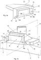
Fig. 2a eine perspektivische Darstellung des Details A inFig. 1 ; -
Fig. 2b eine perspektivische Darstellung des Details B inFig. 1 ; -
Fig. 3 eine Teilschnittdarstellung einer zweiten Ausführungsform der erfindungsgemässen Abstreifervorrichtung; und -
Fig. 4 eine Teilschnittdarstellung der inFig. 3 dargestellten Ausführungsform der erfindungsgemässen Abstreifervorrichtung mit abgedrehter Saugdüse.
-
Fig. 1 a perspective view of a first embodiment of the inventive scraper device; -
Fig. 2a a perspective view of the detail A inFig. 1 ; -
Fig. 2b a perspective view of the detail B inFig. 1 ; -
Fig. 3 a partial sectional view of a second embodiment of the inventive stripper device; and -
Fig. 4 a partial sectional view of inFig. 3 illustrated embodiment of the inventive stripper with abgerehter suction nozzle.
Die
Alternativ kann die Saugdüse 4 unterhalb der Bodenreinigungsmaschine 2 angebracht sein und schwenkbar z.B. via eine als Saugdüsenarm (
Die in den
Das erste Kupplungsteil 14 umfasst einen ersten Magneten 16, während das zweite Kupplungsteil 15 einen zweiten Magneten 17 oder alternativ ein ferromagnetisches Teil umfasst, so dass das erste und zweite Kupplungsteil 14, 15 im montierten Zustand der Abstreifervorrichtung 1 gegeneinander gezogen werden. Der erste und zweite Magnet 16, 17 umfassen beispielhaft je einen Permanentmagneten, welche bezüglich ihrer Polarität so im ersten, respektive zweiten Kupplungsteil 14, 15 angeordnet sind, dass die Saugdüse 4 durch die Magnetkraft gegen die Haltevorrichtung 3 gezogen wird. Alternativ kann auch nur einer der ersten und zweiten Magnete 16, 17 einen Permanentmagneten oder einen Elektromagneten umfassen und anstelle des zweiten Magneten 17 kann ein ferromagnetisches Teil am anderen Kupplungsteil 14, 15 angeordnet sein, wobei im Fall eines Elektromagneten, dieser vorzugsweise am ersten Kupplungsteil 14 angeordnet ist, welches im vorliegenden ersten Ausführungsbeispiel an der Haltevorrichtung 3 angeordnet ist, so dass der Elektromagnet mit elektrischer Energie von der Bodenreinigungsmaschine 2 versorgt werden kann und keine separate Energiequelle notwendig ist. In weiteren Ausführungsformen können die ersten und zweiten Magnete 16, 17 auch je mehrere Permanentmagnete, z.B. 2 bis 10 Stück umfassen. Die ersten und zweiten Magnete 16, 17 können als Polyeder (Würfel, Quader), z.B. mit einer viereckigen oder rechteckigen Querschnittsfläche oder auch als Zylinder ausgebildet sein. Geeignete Magnetmaterialien sind: Neodym-Magneten, Hartferrit-Magneten, AlNiCo-Magneten, SmCo-Magneten, Kunststoffgebundene Magneten oder Stahl. Die Abreisskraft der durch die ersten und zweiten Magnete 16, 17 gebildeten Magnetkupplung beträgt vorzugsweise zwischen 1 N (Newton) bis 1'000 N (Newton).The
Ferner ist das erste Kupplungsteil 14 als weibliche Kupplungsstruktur 18 ausgebildet und das zweite Kupplungsteil 15 ist als komplementäre männliche Kupplungsstruktur 19 ausgebildet. Die weiblichen und die männlichen Kupplungsstrukturen 18, 19 sind in der Vorwärtsbewegungsrichtung X miteinander lösbar in Eingriff bringbar und gegen die Oberseite 13 der Saugdüse 4 und transversal zur Vorwärtsbewegungsrichtung X formschlüssig miteinander verbindbar. Durch die weiblichen und männlichen Kupplungsstrukturen 18, 19 wird die Kupplung zusätzlich zu den ersten und zweiten Magneten 16, 17 durch Formschluss stabilisiert, so dass diese nur in einer Abkopplungs-Drehrichtung (
Wie in
Die Erhebung 26 ist keilförmig ausgebildet, wobei die obere Anlagefläche 28 der Erhebung 26 gegen die auf der Oberseite 13 des Rahmens 5 aufliegende Auflagefläche 24 der Platte 25 und die erste und die zweite seitliche Anlagefläche 29a, 29b der Erhebung 26 gegen die Mittelebene 20 abgeschrägt sind, so dass sich die Erhebung 26 in Richtung der gegen die Haltevorrichtung 3 gerichteten Vorderseite 30 der Erhebung 26 verjüngt. Die Winkel zwischen der abgeschrägten oberen Anlagefläche und der Oberseite 13 des Rahmens 5 und zwischen der ersten, respektive zweiten seitliche Anlagefläche 29a, 29b und der der Mittelebene 20 können beispielsweise und nicht einschränkend mindestens 5°, vorzugsweise mindestens 15° betragen.The
Die Erhebung 26 umfasst im Bereich der Auflagefläche 24 der Platte 25 zwei seitlich über die erste und zweite Seitenfläche 29a, 29b hinausragende Absätze 38a, 38b. Dazu passend umfasst die Vertiefung 27 im Bereich der Unterseite 34 der weiblichen Kupplungsstruktur 18 zwei seitliche Ausnehmungen 39a, 39b zur Aufnahme der an der Erhebung 26 angeordneten Absätze 38a, 38b im angekoppelten Zustand der Saugdüse 4.The
Komplementär zur Erhebung 26 umfasst die Vertiefung 27 eine gegen die Unterseite 34 der weiblichen Kupplungsstruktur 18 abgeschrägte obere Anlagefläche 31 der Vertiefung 27 und eine erste und zweite seitliche Anlagefläche 32a, 32b der Vertiefung 27, welche gegen die Mittelebene 20 abgeschrägt sind, so dass sich gegen die Vertiefung 27 in Richtung der gegen die Saugdüse 4 gerichteten Vorderseite 33 der Vertiefung 27 erweitert. Ferner geht die Unterseite 34 der weiblichen Kupplungsstruktur 18 mit einer Rundung 40 in die vom Rahmen 5 der Saugdüse 4 entfernt angeordnete Rückseite 41 der Vertiefung 27 über. Aufgrund der Rundung 40 bildet die Rückseite 41 der Vertiefung 27 im Bereich der Unterseite 34 der weiblichen Kupplungsstruktur 18 für die ebene Vorderseite 30 der Erhebung 26 bei der Abkopplung eine zur Mittelebene 20 transversale Drehachse (Linienkontakt). Die Anordnung und Ausbildung der Rundung 40 ist so gewählt, dass durch die Lage der Abkopplungs-Drehachse 48 (
Gegen die Unterseite 34 der weiblichen Kupplungsstruktur 18 wird die Erhebung 26 mittels Kraftschluss in der Vertiefung 27 gehalten, welcher durch die Anziehung der ersten und zweiten Magnete 16, 17 verursacht wird.Against the bottom 34 of the
Die Saugdüse 4 ist beispielhaft und nicht einschränkend auf ihrer Länge zwischen dem ersten Ende 22 und dem zweiten Ende 23 gekrümmt. Durch das im Bereich der Frontseite 6 der Saugdüse 4 angeordnete vordere Abstreiferblatt 10 und das im Bereich der Rückseite 7 der Saugdüse 4 angeordnete hintere Abstreiferblatt 9 wird durch das hintere Abstreiferblatt 9, das vordere Abstreiferblatt 10 und die Unterseite 21 des Rahmens 5 der bodenseitig offene Saugkanal 11 gebildet.The
Der Rahmen 5 der Saugdüse 4 kann, beispielhaft und nicht einschränkend, zweiteilig ausgebildet sein (
Die in den
Diese zweite Ausführungsform ermöglicht eine Kopplung des an der Saugdüse 4 angeordneten Saugstutzens 12 mit dem an der Haltevorrichtung 3 angeordneten Rohrstutzen 45, welcher seinerseits mit dem Saugschlauch (nicht gezeichnet) der Bodenreinigungsmaschine 2 verbunden ist, per Magnetkraft. Gleichzeitig mit dem An- bzw. Abkoppeln der Saugdüse 4 an die Haltevorrichtung 3 wird somit auch die Saugdüse 4 mit dem an der Bodenreinigungsmaschine 2 befestigten Saugschlauch verbunden bzw. getrennt..This second embodiment allows a coupling of the arranged at the
Ferner ist der Rahmen 5 der Saugdüse 4, beispielhaft und nicht einschränkend, zweiteilig ausgebildet und umfasst ein oberes Bauteil 37 und einen unteres Bauteil 35. Das obere Bauteil 37 wird oben durch die Oberseite 13 des Rahmens 5 begrenzt und weist einen gegen die Unterseite 21 des Rahmens 5 offenen Hohlraum auf, in welchen das untere Bauteil 35 teilweise oder ganz eingeführt ist. In diesem Hohlraum verbleibt zwischen dem oberen und dem unteren Bauteil 37, 35 im Bereich der Frontseite 6 des Rahmens 5 und im Bereich der Rückseite 7 je ein sich über die gesamte Länge des unteren Bauteils 35 erstreckender Zwischenraum, in welchen das vordere, respektive das hintere Abstreiferblatt 9, 10 eingeklemmt sind.Further, the
Durch das im Bereich der Frontseite 6 der Saugdüse 4 angeordnete vordere Abstreiferblatt 10 und das im Bereich der Rückseite 7 der Saugdüse 4 angeordnete hintere Abstreiferblatt 9 wird durch das hintere Abstreiferblatt 9, das vordere Abstreiferblatt 10 und die Unterseite 21 des Rahmens 5 ein bodenseitig offener Saugkanal 11 gebildet, welcher in die das untere Bauteil 35 des Rahmens 5 vertikal durchdringende Saugöffnung 36 der Saugdüse 4 mündet. An der gegen die Oberseite 13 des Rahmens 5 der Saugdüse 4 gerichteten Oberfläche des unteren Bauteils 35 ist der Saugstutzen 12 angeordnet, welcher durch eine vertikale Öffnung im oberen Bauteil 37 durchgeführt wird und welcher den Anschluss einer Absaugvorrichtung ermöglicht. Das untere Bauteil 35 umfasst in der Vorwärtsbewegungsrichtung X zwei Seitenflächen, welche an der Unterseite 21 der Saugdüse 4 orthogonal zur Vorwärtsbewegungsrichtung X einen Abstand zueinander aufweisen, wobei sich dieser Abstand gegen die Oberseite 13 der Saugdüse 4 verringert und der Hohlraum im oberen Bauteil 37 sich ebenfalls gegen die Oberseite 13 der Saugdüse 4 verjüngt, so dass die Abstreiferblätter 9, 10 durch Verkeilung oder Einhängen fest an der Saugdüse fixiert werden.By arranged in the
Die erfindungsgemässe Abstreifervorrichtung 1 ermöglicht ein einfaches und schnelles Abkoppeln der Saugdüse 4 von der Haltevorrichtung 3, wobei das erfindungsgemässe Verfahren zur Abkopplung der Saugdüse 4 von der Haltevorrichtung 3 die folgenden Schritte umfasst:
- A) Manuelles Ergreifen der Saugdüse 4 bei einer leicht abgekippten Bodenreinigungsmaschine 2;
- B)
Drehen der Saugdüse 4 um die durch die an der weiblichen Kupplungsstruktur 18angebrachte Rundung 40 und dieVorderseite 30der Erhebung 26 der männlichen Kupplungsstruktur 19 definierte Abkopplungs-Drehachse 48 (Fig. 4 ); - C) Bewegen der Saugdüse 4 gegen die
Unterseite 34 der weiblichen Kupplungsstruktur 18 bis die männliche und die weibliche Kupplungsstruktur 18, 19 ausser Eingriff sind; und - D)
Entfernen der Saugdüse 4von der Bodenreinigungsmaschine 2.
- A) Manual gripping of the
suction nozzle 4 in a slightly tiltedfloor cleaning machine 2; - B) rotating the
suction nozzle 4 about the by the attached to thefemale coupling structure 18 rounding 40 and thefront 30 of thecollection 26 of themale coupling structure 19 defineduncoupling rotation axis 48Fig. 4 ); - C) moving the
suction nozzle 4 against theunderside 34 of thefemale coupling structure 18 until the male andfemale coupling structures - D) removing the
suction nozzle 4 from thefloor cleaning machine 2.
Bei der ersten Ausführungsform der erfindungsgemässen Abstreifervorrichtung 1 gemäss den
Obwohl wie oben beschrieben verschiedene Ausführungsformen der vorliegenden Erfindung vorliegen, sind diese so zu verstehen, dass die verschiedenen Merkmale sowohl einzeln als auch in jeder beliebigen Kombination verwendet werden können. Die Erfindung ist daher nicht einfach auf die oben beschriebenen, besonders bevorzugten Ausführungsformen beschränkt.While various embodiments of the present invention are described above, it should be understood that the various features may be used both individually and in any combination. The invention is therefore not limited to the particularly preferred embodiments described above.
Claims (15)
- A stripping device (1) for a floor cleaning machine (2), wherein the stripping device (1) comprises:a holding device (3) which can be fastened to a floor cleaning machine (2);a suction nozzle (4) which can be detachably coupled to the holding device (3) andwhich comprises the following:i) an elongate frame (5) with a front side (6) arranged transversely to a forward movement direction (X) of a floor cleaning machine (2), a rear side (7), and a hollow space (8) open at the bottom on the frame (5); andii) a suction pipe (12) which - viewed in vertical direction during operation of the stripping device (1) - is arranged on an upper side (13) of the frame (5) and opens into the hollow space (8); whereinthe holding device (3) comprises a first coupling part (14) and the suction nozzle (4) comprises a second coupling part (15) which can be detachably engaged in the first coupling part (14),characterized in thatone of the first and second coupling parts (14, 15) comprises a first magnet (16) and the other one of the first and second coupling parts (14, 15) comprises a second magnet (17) or a ferromagnetic part, so that the first and second coupling parts (14, 15) are pulled toward one another viewed in the forward movement direction (X); and one of the first and second coupling parts (14, 15) is formed as a female coupling structure (18) and the other one of the first and second coupling parts (14, 15) is formed as a male coupling structure (19); whereinthe female and the male coupling structures (18, 19) can be detachably engaged in one another in the forward movement direction (X) and can be connected to one another by positive connection toward the upper side (13) of the suction nozzle (4) and transversely to the forward movement direction (X).
- The stripping device according to Claim 1, characterized in that the female coupling structure (18) is formed as recess (27) and comprises a rounding (40) which transitions from a lower side (34) of the female coupling structure (18) into a rear side (41) of the recess (27), which is distant from the frame (5) of the suction nozzle (4).
- The stripping device according to Claim 1 or 2, characterized in that the suction pipe (12) comprises a pipe bend (44) which is bent toward the front side (6) of the frame (5), and the first coupling part (14) comprises a pipe socket (45) arranged in alignment with an outlet opening of the pipe bend (44).
- The stripping device according to Claim 3, characterized in that, on a free end of the pipe bend (44), a resilient sealing lip (46) with a projection or a flange with an annular gasket is arranged.
- The stripping device according to any one of Claims 1 to 4, characterized in that the male coupling structure (19) comprises a wedge-shaped elevation (26) with respect to the forward movement direction (X), and the female coupling structure (18) comprises a deepening (27) of complementary form.
- The stripping device according to Claim 5, characterized in that the elevation (26) comprises an upper contact surface (28) and a first and second lateral contact surface (29a, 29b), wherein the upper contact surface (28) is beveled toward the upper side (13) of the frame (5), and the first and the second lateral contact surfaces (29a, 29b) are beveled toward a central plane (20) of the suction nozzle (4), so that the elevation (26) narrows in a direction toward the holding device 3.
- The stripping device according to Claim 6, characterized in that the elevation (26) comprises two ledges (38a, 38b) protruding laterally across the first and second side surfaces (29a, 29b), and the deepening (27) comprises two lateral recesses (39a, 39b) for accommodating the ledges (38a, 38b) arranged on the elevation (26) in the coupled state of the suction nozzle (4).
- The stripping device according to any one of Claims 1 to 7, characterized in that the first and second magnets (16, 17) each comprise one or more permanent magnets.
- The stripping device according to any one of Claims 1 to 7, characterized in that one of the first and second magnets (16, 17) comprises an electromagnet.
- The stripping device according to any one of Claims 1 to 9, characterized in that the pull-off force between the first and second magnets (16, 17) is at least 0.5 N, preferably at least 1 N.
- The stripping device according to any one of Claims 1 to 10, characterized in that the pull-off force between the first and second magnets (16, 17) is at most 1500 N, preferably at most 1000 N.
- The stripping device according to any one of Claims 6 to 11, characterized in that the beveled upper contact surface (28) with the upper side (13) of the frame (5) and the first and the second lateral contact surfaces (29a, 29b) with the central plane (20) enclose an angle of at least 5°, preferably at least 15°.
- The stripping device according to any one of Claims 1 to 12, characterized in that the suction nozzle (4) comprises a rear stripping sheet (9) which delimits the hollow space (8) in the region of the rear side (7) and a front stripping sheet (10) which delimits the hollow space (8) in the region of the front side (6), so that a suction channel (11) which is open on the bottom side is formed.
- A method for coupling a suction nozzle (4) of a holding device (3) of a stripping device according to any one of Claims 1 to 13, comprising the steps:a) turning the suction nozzle (4) about an uncoupling rotation axis 48 defined by the rounding (40) provided on the female coupling structure (18) and the front side (30) of the elevation (26) of the male coupling structure 19;b) moving the suction nozzle (4) against a lower side (34) of the female coupling structure (18) until the male and the female coupling structures (18, 19) are disengaged; andc) removing the suction nozzle (4) from the floor cleaning machine (2).
- The method according to Claim 14, characterized by the additional step:
separating the suction nozzle (4) from a suction tube fastened on a floor cleaning machine (2).
Priority Applications (4)
| Application Number | Priority Date | Filing Date | Title |
|---|---|---|---|
| DK17179773.1T DK3424397T3 (en) | 2017-07-05 | 2017-07-05 | Stripping device for a floor cleaner |
| EP17179773.1A EP3424397B1 (en) | 2017-07-05 | 2017-07-05 | Stripping device for a floor cleaning machine |
| PL17179773T PL3424397T3 (en) | 2017-07-05 | 2017-07-05 | Stripping device for a floor cleaning machine |
| CN201810732706.5A CN109199257A (en) | 2017-07-05 | 2018-07-05 | Scratch device for floor cleaner |
Applications Claiming Priority (1)
| Application Number | Priority Date | Filing Date | Title |
|---|---|---|---|
| EP17179773.1A EP3424397B1 (en) | 2017-07-05 | 2017-07-05 | Stripping device for a floor cleaning machine |
Publications (2)
| Publication Number | Publication Date |
|---|---|
| EP3424397A1 EP3424397A1 (en) | 2019-01-09 |
| EP3424397B1 true EP3424397B1 (en) | 2019-11-27 |
Family
ID=59294991
Family Applications (1)
| Application Number | Title | Priority Date | Filing Date |
|---|---|---|---|
| EP17179773.1A Active EP3424397B1 (en) | 2017-07-05 | 2017-07-05 | Stripping device for a floor cleaning machine |
Country Status (4)
| Country | Link |
|---|---|
| EP (1) | EP3424397B1 (en) |
| CN (1) | CN109199257A (en) |
| DK (1) | DK3424397T3 (en) |
| PL (1) | PL3424397T3 (en) |
Families Citing this family (3)
| Publication number | Priority date | Publication date | Assignee | Title |
|---|---|---|---|---|
| PL3754112T3 (en) * | 2019-06-18 | 2023-10-02 | Marcel Boschung Ag | Suction machine with a releasable suction inlet |
| WO2021113224A1 (en) * | 2019-12-02 | 2021-06-10 | Techtronic Cordless Gp | Floor cleaner having a removable nozzle |
| CN115379097B (en) * | 2022-08-24 | 2023-11-07 | 深圳禹航空间技术有限公司 | Windscreen wiper device based on permanent magnet non-directional synchronous motor and magnetic coupling transmission |
Family Cites Families (8)
| Publication number | Priority date | Publication date | Assignee | Title |
|---|---|---|---|---|
| ATE449557T1 (en) * | 2006-10-19 | 2009-12-15 | Hako Gmbh | FLOOR CLEANING MACHINE WITH A SWIVELING SQUEEGEE FOOT |
| EP2011427A1 (en) | 2007-07-04 | 2009-01-07 | Comac S.p.A. | Floor wiper for floor cleansing and drying machines |
| CN101292853B (en) * | 2008-05-09 | 2011-04-06 | 艾和金 | Drive type floor cleaning machine |
| IT1391610B1 (en) * | 2008-11-05 | 2012-01-11 | Ip Cleaning S P A | FLOOR WASHER |
| TWI460027B (en) * | 2012-07-06 | 2014-11-11 | Uni Ring Tech Co Ltd | Quick release self-propelled apparatus cleaning method of cleaning mechanism |
| TW201605396A (en) * | 2014-08-01 | 2016-02-16 | Uni Ring Tech Co Ltd | Cleaning member, cleaning device and cleaning method thereof |
| CN204813713U (en) * | 2015-07-01 | 2015-12-02 | 广东浩宇清洁环保设备有限公司 | Absorb water and take off improvement structure |
| CN105962860A (en) * | 2016-07-17 | 2016-09-28 | 刘祥发 | Multipurpose mop with floor sweeping and water wiping functions |
-
2017
- 2017-07-05 DK DK17179773.1T patent/DK3424397T3/en active
- 2017-07-05 EP EP17179773.1A patent/EP3424397B1/en active Active
- 2017-07-05 PL PL17179773T patent/PL3424397T3/en unknown
-
2018
- 2018-07-05 CN CN201810732706.5A patent/CN109199257A/en active Pending
Non-Patent Citations (1)
| Title |
|---|
| None * |
Also Published As
| Publication number | Publication date |
|---|---|
| PL3424397T3 (en) | 2020-05-18 |
| EP3424397A1 (en) | 2019-01-09 |
| CN109199257A (en) | 2019-01-15 |
| DK3424397T3 (en) | 2020-03-02 |
Similar Documents
| Publication | Publication Date | Title |
|---|---|---|
| EP3424397B1 (en) | Stripping device for a floor cleaning machine | |
| DE68917890T2 (en) | Hose coupling. | |
| DE602005004317T2 (en) | Fastening device for electrical connectors and use thereof | |
| DE2550790A1 (en) | STRIPPING DEVICE FOR SLIDES ON MACHINE TOOLS | |
| DE102018105461A1 (en) | cleaner | |
| EP3491988B1 (en) | Click nozzle | |
| DE102014117418A1 (en) | Floor nozzle for a floor care appliance and method for making a floor nozzle for a floor care appliance | |
| DE3136401C2 (en) | Multipurpose cleaning device | |
| EP2949253B1 (en) | Suction cup for a floor cleaning machine | |
| EP3393320B1 (en) | Suction nozzle for a hard surface cleaning device and hard surface cleaning device having a suction nozzle of this type | |
| WO2019219582A1 (en) | Wet cleaning device for wet cleaning a floor surface | |
| EP3449794B1 (en) | Cleaning device with a motor-driven oscillating plate | |
| DE102013204394A1 (en) | Floor cleaning machine with a coupling device for an attachment | |
| DE2553061C2 (en) | ||
| DE102018118642A1 (en) | Interface for battery pack | |
| DE3246887A1 (en) | Handle-fastening coupling, in particular for household and garden implements | |
| EP3006636B1 (en) | Wall drain with pump | |
| DE2701350A1 (en) | CONNECTOR DEVICE | |
| EP0019833B1 (en) | Releasable stick-mounting for brooms or scrubbers | |
| EP3274511A1 (en) | Sweeping machine | |
| DE202007007294U1 (en) | Motor propelled machine tool e.g. for machine tool, has movable pivotable tools which can be propelled with propelable tool shaft and at whose face mounting device is arranged | |
| EP3185743B1 (en) | Vacuum nozzle and vacuum cleaner for hard surfaces | |
| DE19956130C1 (en) | Clips for joining two components comprise lugs gripping behind edges, slide pieces, holder-lugs, catches and depression for tool | |
| DE102015109778B3 (en) | Scrub deck for a floor cleaning machine | |
| DE102016007196A1 (en) | Attachments for window wipers for receiving the dirty water and equipped with the attachments window wiper |
Legal Events
| Date | Code | Title | Description |
|---|---|---|---|
| PUAI | Public reference made under article 153(3) epc to a published international application that has entered the european phase |
Free format text: ORIGINAL CODE: 0009012 |
|
| STAA | Information on the status of an ep patent application or granted ep patent |
Free format text: STATUS: REQUEST FOR EXAMINATION WAS MADE |
|
| 17P | Request for examination filed |
Effective date: 20170705 |
|
| AK | Designated contracting states |
Kind code of ref document: A1 Designated state(s): AL AT BE BG CH CY CZ DE DK EE ES FI FR GB GR HR HU IE IS IT LI LT LU LV MC MK MT NL NO PL PT RO RS SE SI SK SM TR |
|
| AX | Request for extension of the european patent |
Extension state: BA ME |
|
| GRAP | Despatch of communication of intention to grant a patent |
Free format text: ORIGINAL CODE: EPIDOSNIGR1 |
|
| STAA | Information on the status of an ep patent application or granted ep patent |
Free format text: STATUS: GRANT OF PATENT IS INTENDED |
|
| RIC1 | Information provided on ipc code assigned before grant |
Ipc: A47L 13/11 20060101ALI20190627BHEP Ipc: A47L 11/30 20060101AFI20190627BHEP Ipc: A47L 11/40 20060101ALI20190627BHEP |
|
| INTG | Intention to grant announced |
Effective date: 20190723 |
|
| GRAS | Grant fee paid |
Free format text: ORIGINAL CODE: EPIDOSNIGR3 |
|
| GRAA | (expected) grant |
Free format text: ORIGINAL CODE: 0009210 |
|
| STAA | Information on the status of an ep patent application or granted ep patent |
Free format text: STATUS: THE PATENT HAS BEEN GRANTED |
|
| AK | Designated contracting states |
Kind code of ref document: B1 Designated state(s): AL AT BE BG CH CY CZ DE DK EE ES FI FR GB GR HR HU IE IS IT LI LT LU LV MC MK MT NL NO PL PT RO RS SE SI SK SM TR |
|
| REG | Reference to a national code |
Ref country code: GB Ref legal event code: FG4D Free format text: NOT ENGLISH |
|
| REG | Reference to a national code |
Ref country code: CH Ref legal event code: EP |
|
| REG | Reference to a national code |
Ref country code: AT Ref legal event code: REF Ref document number: 1205780 Country of ref document: AT Kind code of ref document: T Effective date: 20191215 |
|
| REG | Reference to a national code |
Ref country code: DE Ref legal event code: R096 Ref document number: 502017002974 Country of ref document: DE |
|
| REG | Reference to a national code |
Ref country code: IE Ref legal event code: FG4D Free format text: LANGUAGE OF EP DOCUMENT: GERMAN |
|
| REG | Reference to a national code |
Ref country code: CH Ref legal event code: NV Representative=s name: DR. LUSUARDI AG, CH |
|
| REG | Reference to a national code |
Ref country code: DK Ref legal event code: T3 Effective date: 20200226 |
|
| REG | Reference to a national code |
Ref country code: SE Ref legal event code: TRGR |
|
| REG | Reference to a national code |
Ref country code: LT Ref legal event code: MG4D |
|
| PG25 | Lapsed in a contracting state [announced via postgrant information from national office to epo] |
Ref country code: BG Free format text: LAPSE BECAUSE OF FAILURE TO SUBMIT A TRANSLATION OF THE DESCRIPTION OR TO PAY THE FEE WITHIN THE PRESCRIBED TIME-LIMIT Effective date: 20200227 Ref country code: FI Free format text: LAPSE BECAUSE OF FAILURE TO SUBMIT A TRANSLATION OF THE DESCRIPTION OR TO PAY THE FEE WITHIN THE PRESCRIBED TIME-LIMIT Effective date: 20191127 Ref country code: GR Free format text: LAPSE BECAUSE OF FAILURE TO SUBMIT A TRANSLATION OF THE DESCRIPTION OR TO PAY THE FEE WITHIN THE PRESCRIBED TIME-LIMIT Effective date: 20200228 Ref country code: NO Free format text: LAPSE BECAUSE OF FAILURE TO SUBMIT A TRANSLATION OF THE DESCRIPTION OR TO PAY THE FEE WITHIN THE PRESCRIBED TIME-LIMIT Effective date: 20200227 Ref country code: LT Free format text: LAPSE BECAUSE OF FAILURE TO SUBMIT A TRANSLATION OF THE DESCRIPTION OR TO PAY THE FEE WITHIN THE PRESCRIBED TIME-LIMIT Effective date: 20191127 Ref country code: LV Free format text: LAPSE BECAUSE OF FAILURE TO SUBMIT A TRANSLATION OF THE DESCRIPTION OR TO PAY THE FEE WITHIN THE PRESCRIBED TIME-LIMIT Effective date: 20191127 |
|
| REG | Reference to a national code |
Ref country code: NL Ref legal event code: FP |
|
| PG25 | Lapsed in a contracting state [announced via postgrant information from national office to epo] |
Ref country code: IS Free format text: LAPSE BECAUSE OF FAILURE TO SUBMIT A TRANSLATION OF THE DESCRIPTION OR TO PAY THE FEE WITHIN THE PRESCRIBED TIME-LIMIT Effective date: 20200327 Ref country code: RS Free format text: LAPSE BECAUSE OF FAILURE TO SUBMIT A TRANSLATION OF THE DESCRIPTION OR TO PAY THE FEE WITHIN THE PRESCRIBED TIME-LIMIT Effective date: 20191127 Ref country code: HR Free format text: LAPSE BECAUSE OF FAILURE TO SUBMIT A TRANSLATION OF THE DESCRIPTION OR TO PAY THE FEE WITHIN THE PRESCRIBED TIME-LIMIT Effective date: 20191127 |
|
| PG25 | Lapsed in a contracting state [announced via postgrant information from national office to epo] |
Ref country code: AL Free format text: LAPSE BECAUSE OF FAILURE TO SUBMIT A TRANSLATION OF THE DESCRIPTION OR TO PAY THE FEE WITHIN THE PRESCRIBED TIME-LIMIT Effective date: 20191127 |
|
| PG25 | Lapsed in a contracting state [announced via postgrant information from national office to epo] |
Ref country code: ES Free format text: LAPSE BECAUSE OF FAILURE TO SUBMIT A TRANSLATION OF THE DESCRIPTION OR TO PAY THE FEE WITHIN THE PRESCRIBED TIME-LIMIT Effective date: 20191127 Ref country code: PT Free format text: LAPSE BECAUSE OF FAILURE TO SUBMIT A TRANSLATION OF THE DESCRIPTION OR TO PAY THE FEE WITHIN THE PRESCRIBED TIME-LIMIT Effective date: 20200419 Ref country code: EE Free format text: LAPSE BECAUSE OF FAILURE TO SUBMIT A TRANSLATION OF THE DESCRIPTION OR TO PAY THE FEE WITHIN THE PRESCRIBED TIME-LIMIT Effective date: 20191127 Ref country code: CZ Free format text: LAPSE BECAUSE OF FAILURE TO SUBMIT A TRANSLATION OF THE DESCRIPTION OR TO PAY THE FEE WITHIN THE PRESCRIBED TIME-LIMIT Effective date: 20191127 Ref country code: RO Free format text: LAPSE BECAUSE OF FAILURE TO SUBMIT A TRANSLATION OF THE DESCRIPTION OR TO PAY THE FEE WITHIN THE PRESCRIBED TIME-LIMIT Effective date: 20191127 |
|
| REG | Reference to a national code |
Ref country code: DE Ref legal event code: R097 Ref document number: 502017002974 Country of ref document: DE |
|
| PG25 | Lapsed in a contracting state [announced via postgrant information from national office to epo] |
Ref country code: SM Free format text: LAPSE BECAUSE OF FAILURE TO SUBMIT A TRANSLATION OF THE DESCRIPTION OR TO PAY THE FEE WITHIN THE PRESCRIBED TIME-LIMIT Effective date: 20191127 Ref country code: SK Free format text: LAPSE BECAUSE OF FAILURE TO SUBMIT A TRANSLATION OF THE DESCRIPTION OR TO PAY THE FEE WITHIN THE PRESCRIBED TIME-LIMIT Effective date: 20191127 |
|
| PLBE | No opposition filed within time limit |
Free format text: ORIGINAL CODE: 0009261 |
|
| STAA | Information on the status of an ep patent application or granted ep patent |
Free format text: STATUS: NO OPPOSITION FILED WITHIN TIME LIMIT |
|
| 26N | No opposition filed |
Effective date: 20200828 |
|
| PG25 | Lapsed in a contracting state [announced via postgrant information from national office to epo] |
Ref country code: SI Free format text: LAPSE BECAUSE OF FAILURE TO SUBMIT A TRANSLATION OF THE DESCRIPTION OR TO PAY THE FEE WITHIN THE PRESCRIBED TIME-LIMIT Effective date: 20191127 |
|
| PG25 | Lapsed in a contracting state [announced via postgrant information from national office to epo] |
Ref country code: MC Free format text: LAPSE BECAUSE OF FAILURE TO SUBMIT A TRANSLATION OF THE DESCRIPTION OR TO PAY THE FEE WITHIN THE PRESCRIBED TIME-LIMIT Effective date: 20191127 |
|
| PG25 | Lapsed in a contracting state [announced via postgrant information from national office to epo] |
Ref country code: FR Free format text: LAPSE BECAUSE OF NON-PAYMENT OF DUE FEES Effective date: 20200731 Ref country code: IE Free format text: LAPSE BECAUSE OF NON-PAYMENT OF DUE FEES Effective date: 20200705 |
|
| GBPC | Gb: european patent ceased through non-payment of renewal fee |
Effective date: 20210705 |
|
| PG25 | Lapsed in a contracting state [announced via postgrant information from national office to epo] |
Ref country code: GB Free format text: LAPSE BECAUSE OF NON-PAYMENT OF DUE FEES Effective date: 20210705 |
|
| PG25 | Lapsed in a contracting state [announced via postgrant information from national office to epo] |
Ref country code: TR Free format text: LAPSE BECAUSE OF FAILURE TO SUBMIT A TRANSLATION OF THE DESCRIPTION OR TO PAY THE FEE WITHIN THE PRESCRIBED TIME-LIMIT Effective date: 20191127 Ref country code: MT Free format text: LAPSE BECAUSE OF FAILURE TO SUBMIT A TRANSLATION OF THE DESCRIPTION OR TO PAY THE FEE WITHIN THE PRESCRIBED TIME-LIMIT Effective date: 20191127 Ref country code: CY Free format text: LAPSE BECAUSE OF FAILURE TO SUBMIT A TRANSLATION OF THE DESCRIPTION OR TO PAY THE FEE WITHIN THE PRESCRIBED TIME-LIMIT Effective date: 20191127 |
|
| PG25 | Lapsed in a contracting state [announced via postgrant information from national office to epo] |
Ref country code: MK Free format text: LAPSE BECAUSE OF FAILURE TO SUBMIT A TRANSLATION OF THE DESCRIPTION OR TO PAY THE FEE WITHIN THE PRESCRIBED TIME-LIMIT Effective date: 20191127 |
|
| P01 | Opt-out of the competence of the unified patent court (upc) registered |
Effective date: 20230627 |
|
| PGFP | Annual fee paid to national office [announced via postgrant information from national office to epo] |
Ref country code: PL Payment date: 20240619 Year of fee payment: 8 |
|
| PGFP | Annual fee paid to national office [announced via postgrant information from national office to epo] |
Ref country code: LU Payment date: 20240719 Year of fee payment: 8 |
|
| PGFP | Annual fee paid to national office [announced via postgrant information from national office to epo] |
Ref country code: NL Payment date: 20240719 Year of fee payment: 8 |
|
| PGFP | Annual fee paid to national office [announced via postgrant information from national office to epo] |
Ref country code: DE Payment date: 20240719 Year of fee payment: 8 |
|
| PGFP | Annual fee paid to national office [announced via postgrant information from national office to epo] |
Ref country code: DK Payment date: 20240726 Year of fee payment: 8 |
|
| PGFP | Annual fee paid to national office [announced via postgrant information from national office to epo] |
Ref country code: BE Payment date: 20240719 Year of fee payment: 8 |
|
| PGFP | Annual fee paid to national office [announced via postgrant information from national office to epo] |
Ref country code: CH Payment date: 20240801 Year of fee payment: 8 |
|
| PGFP | Annual fee paid to national office [announced via postgrant information from national office to epo] |
Ref country code: AT Payment date: 20240722 Year of fee payment: 8 |
|
| PGFP | Annual fee paid to national office [announced via postgrant information from national office to epo] |
Ref country code: SE Payment date: 20240719 Year of fee payment: 8 Ref country code: IT Payment date: 20240725 Year of fee payment: 8 |