EP3416245A1 - Connecteur de type à contact à pression et son procédé de fabrication - Google Patents
Connecteur de type à contact à pression et son procédé de fabrication Download PDFInfo
- Publication number
- EP3416245A1 EP3416245A1 EP18185332.6A EP18185332A EP3416245A1 EP 3416245 A1 EP3416245 A1 EP 3416245A1 EP 18185332 A EP18185332 A EP 18185332A EP 3416245 A1 EP3416245 A1 EP 3416245A1
- Authority
- EP
- European Patent Office
- Prior art keywords
- flat plate
- plate portion
- spring
- contact type
- pressure contact
- Prior art date
- Legal status (The legal status is an assumption and is not a legal conclusion. Google has not performed a legal analysis and makes no representation as to the accuracy of the status listed.)
- Granted
Links
- 238000004519 manufacturing process Methods 0.000 title description 19
- 239000002184 metal Substances 0.000 claims description 38
- 230000007423 decrease Effects 0.000 claims description 25
- 238000005452 bending Methods 0.000 description 61
- 238000004080 punching Methods 0.000 description 24
- 238000004804 winding Methods 0.000 description 24
- 239000000758 substrate Substances 0.000 description 12
- 238000006073 displacement reaction Methods 0.000 description 7
- 230000009467 reduction Effects 0.000 description 5
- 230000000694 effects Effects 0.000 description 4
- 238000000034 method Methods 0.000 description 4
- 230000008569 process Effects 0.000 description 4
- 230000001681 protective effect Effects 0.000 description 4
- 238000004381 surface treatment Methods 0.000 description 4
- 230000004048 modification Effects 0.000 description 3
- 238000012986 modification Methods 0.000 description 3
- 238000005260 corrosion Methods 0.000 description 2
- 230000007797 corrosion Effects 0.000 description 2
- 239000000463 material Substances 0.000 description 2
- 238000007747 plating Methods 0.000 description 2
- 230000004075 alteration Effects 0.000 description 1
- 230000008901 benefit Effects 0.000 description 1
- 230000015572 biosynthetic process Effects 0.000 description 1
- 238000003825 pressing Methods 0.000 description 1
Images


Classifications
-
- H—ELECTRICITY
- H01—ELECTRIC ELEMENTS
- H01R—ELECTRICALLY-CONDUCTIVE CONNECTIONS; STRUCTURAL ASSOCIATIONS OF A PLURALITY OF MUTUALLY-INSULATED ELECTRICAL CONNECTING ELEMENTS; COUPLING DEVICES; CURRENT COLLECTORS
- H01R13/00—Details of coupling devices of the kinds covered by groups H01R12/70 or H01R24/00 - H01R33/00
- H01R13/02—Contact members
- H01R13/22—Contacts for co-operating by abutting
- H01R13/24—Contacts for co-operating by abutting resilient; resiliently-mounted
- H01R13/2407—Contacts for co-operating by abutting resilient; resiliently-mounted characterized by the resilient means
-
- H—ELECTRICITY
- H01—ELECTRIC ELEMENTS
- H01R—ELECTRICALLY-CONDUCTIVE CONNECTIONS; STRUCTURAL ASSOCIATIONS OF A PLURALITY OF MUTUALLY-INSULATED ELECTRICAL CONNECTING ELEMENTS; COUPLING DEVICES; CURRENT COLLECTORS
- H01R12/00—Structural associations of a plurality of mutually-insulated electrical connecting elements, specially adapted for printed circuits, e.g. printed circuit boards [PCB], flat or ribbon cables, or like generally planar structures, e.g. terminal strips, terminal blocks; Coupling devices specially adapted for printed circuits, flat or ribbon cables, or like generally planar structures; Terminals specially adapted for contact with, or insertion into, printed circuits, flat or ribbon cables, or like generally planar structures
- H01R12/70—Coupling devices
- H01R12/71—Coupling devices for rigid printing circuits or like structures
- H01R12/72—Coupling devices for rigid printing circuits or like structures coupling with the edge of the rigid printed circuits or like structures
- H01R12/73—Coupling devices for rigid printing circuits or like structures coupling with the edge of the rigid printed circuits or like structures connecting to other rigid printed circuits or like structures
-
- H—ELECTRICITY
- H01—ELECTRIC ELEMENTS
- H01R—ELECTRICALLY-CONDUCTIVE CONNECTIONS; STRUCTURAL ASSOCIATIONS OF A PLURALITY OF MUTUALLY-INSULATED ELECTRICAL CONNECTING ELEMENTS; COUPLING DEVICES; CURRENT COLLECTORS
- H01R13/00—Details of coupling devices of the kinds covered by groups H01R12/70 or H01R24/00 - H01R33/00
- H01R13/02—Contact members
- H01R13/22—Contacts for co-operating by abutting
- H01R13/24—Contacts for co-operating by abutting resilient; resiliently-mounted
- H01R13/2407—Contacts for co-operating by abutting resilient; resiliently-mounted characterized by the resilient means
- H01R13/2428—Contacts for co-operating by abutting resilient; resiliently-mounted characterized by the resilient means using meander springs
-
- H—ELECTRICITY
- H01—ELECTRIC ELEMENTS
- H01R—ELECTRICALLY-CONDUCTIVE CONNECTIONS; STRUCTURAL ASSOCIATIONS OF A PLURALITY OF MUTUALLY-INSULATED ELECTRICAL CONNECTING ELEMENTS; COUPLING DEVICES; CURRENT COLLECTORS
- H01R43/00—Apparatus or processes specially adapted for manufacturing, assembling, maintaining, or repairing of line connectors or current collectors or for joining electric conductors
- H01R43/16—Apparatus or processes specially adapted for manufacturing, assembling, maintaining, or repairing of line connectors or current collectors or for joining electric conductors for manufacturing contact members, e.g. by punching and by bending
-
- Y—GENERAL TAGGING OF NEW TECHNOLOGICAL DEVELOPMENTS; GENERAL TAGGING OF CROSS-SECTIONAL TECHNOLOGIES SPANNING OVER SEVERAL SECTIONS OF THE IPC; TECHNICAL SUBJECTS COVERED BY FORMER USPC CROSS-REFERENCE ART COLLECTIONS [XRACs] AND DIGESTS
- Y10—TECHNICAL SUBJECTS COVERED BY FORMER USPC
- Y10T—TECHNICAL SUBJECTS COVERED BY FORMER US CLASSIFICATION
- Y10T29/00—Metal working
- Y10T29/49—Method of mechanical manufacture
- Y10T29/49002—Electrical device making
- Y10T29/49117—Conductor or circuit manufacturing
- Y10T29/49204—Contact or terminal manufacturing
- Y10T29/49206—Contact or terminal manufacturing by powder metallurgy
Definitions
- the present invention relates to a pressure contact type connector, and particularly, to a pressure contact type connector in which a connection terminal is formed in a spiral shape.
- a pressure contact type connector including a connection terminal having elasticity is provided on one substrate, a contact portion is provided on the other substrate, and the substrates are disposed so that the contact portion and the pressure contact type connector come into pressure-contact with each other.
- the connection terminal is formed in a spiral shape so as to have elasticity.
- a pressure contact type connector disclosed in Japanese Unexamined Patent Application Publication No. 2010-118256 has been known.
- Figs. 13A and 13B are views showing a structure of a connection terminal 902 of a pressure contact type connector 900
- Fig. 13A is a plan view showing an outline of the connection terminal 902
- Fig. 13B is a sectional view showing a section taken along line Z-Z shown in Fig. 13A .
- the spiral contactor (connector terminal) 902 is spirally formed from the base 902b toward the center of the tip, and includes a tip 902a at the center of the spiral.
- the spiral contactor 902 includes a groove 902d formed along a longitudinal direction of the spiral contactor 902 at the center in the width direction of the spiral contactor 902, the center is formed in a planar shape or a convex shape, and the spiral contactor 902 includes a protrusion 902aa on the upper surface of the tip 902a.
- the present invention is to provide a pressure contact type connector capable of having a reduced mounting area and obtaining a large elastic force.
- a pressure contact type connector including: an upper flat plate portion which extends in a flat plate shape along a horizontal direction; a lower flat plate portion which extends in a flat plate shape along a horizontal direction and is disposed below the upper flat plate portion; a first spring portion which connects one end portion of the upper flat plate portion and one end portion of the lower flat plate portion and has elasticity in a vertical direction; and a second spring portion which is connected to at least one of the other end portion of the upper flat plate portion opposing the one end portion of the upper flat plate portion while interposing the upper flat plate portion and the other end portion of the lower flat plate portion opposing the one end portion of the lower flat plate portion while interposing the lower flat plate portion, extends toward the other ends of the upper flat plate portion and the lower flat plate portion, includes elasticity in the vertical direction, and is configured to apply a resilient force to the upper flat plate portion, in which the first spring portion and the second spring portion are wound in the same direction about the upper flat plate portion when
- the first spring portion and the second spring portion are formed so that a thickness direction of the first spring portion and a thickness direction of the second spring portion are the horizontal directions, and thus, a reduction in a size of the pressure contact type connector in the horizontal direction is achieved.
- a thickness direction of the first spring portion and a thickness direction of the second spring portion are the horizontal directions, and thus, a reduction in a size of the pressure contact type connector in the horizontal direction is achieved.
- the pressure contact type connector capable of having a reduced mounting area and obtaining a large elastic force.
- the upper flat plate portion may be formed by bending an upper plate portion of a metal plate having an L-shaped portion, which includes the upper plate portion extending along the vertical direction and an intermediate plate portion connected to the lower side of the upper plate portion and extending in one direction in the horizontal direction, so as to extend along the other direction which is a direction in the horizontal direction and is orthogonal to the one direction, and the first spring portion or the second spring portion may be formed by bending the intermediate plate portion so as to be wound around a virtual center line which is set along the vertical direction.
- the metal plate having the L-shaped portion extending along the one direction in the horizontal direction is formed so as to be bent and to extend along the other direction in the horizontal direction, and thus, it is possible to easily configure the upper flat plate portion by bending it once.
- the lower flat plate portion may be formed by bending a lower plate portion of a metal plate having an L-shaped portion, which includes the lower plate portion extending along the vertical direction and an intermediate plate portion connected to the upper side of the lower plate portion and extending in one direction in the horizontal direction, so as to extend along the other direction which is a direction in the horizontal direction and is orthogonal to the one direction, and the first spring portion or the second spring portion may be formed by bending the intermediate plate portion so as to be wound around a virtual center line which is set along the vertical direction.
- the metal plate having the L-shaped portion extending along the one direction in the horizontal direction is formed so as to be bent to extend along the other direction in the horizontal direction, and thus, it is possible to easily configure the lower flat plate portion by bending it once.
- the first spring portion may protrude upward from the one end portion of the lower flat plate portion and may be bent so as to be wound at the upper side of the lower flat plate portion
- the second spring portion may protrude from one of the other end portion of the upper flat plate portion and the other end portion of the lower flat plate portion toward the other, and may be bent so as to be wound at the upper side of the lower flat plate portion.
- the lower flat plate portion does not protrude from the first spring portion and the second spring portion in at least the one end portion of the lower flat plate portion and the other end portion of the lower flat plate portion, it is possible to decrease the mounting area.
- a stopper portion which is formed to protrude upward at a location of noninterference with the first spring portion and the second spring portion, may be connected to the lower flat plate portion, and a height dimension of the stopper portion may be equal to or more than a height dimension of a base portion of each of the first spring portion and the second spring portion connected to the lower flat plate portion, and may be equal to or more than a width dimension in the vertical direction of each of the first spring portion and the second spring portion.
- the stopper portion may be provided outside the first spring portion and the second spring portion.
- the stopper portion is provided outside the first spring portion and the second spring portion, it is possible to prevent a finger or the like from coming into contact with the spring portions from the side, and thus, it is possible to prevent the first spring portion and the second spring portion from being damaged.
- the stopper can function as a guide.
- the width dimensions in the vertical direction of the first spring portion and the second spring portion may decrease from the lower side toward the upper side in the entirety thereof.
- the width dimensions in the vertical direction of the first spring portion and the second spring portion decrease from the lower side toward the upper side, it is possible to obtain the elastic force required for a stable electrical connection, and it is possible to lengthen the strokes of the first spring portion and the second spring portion.
- the width dimensions may decrease from the lower side toward the upper side in the entirety thereof, and the widths may partially increase.
- the second spring portion may be connected to the other end portion of the lower flat plate portion, and an auxiliary upper flat plate portion extending from the second spring portion may be provided on the lower side of the upper flat plate portion.
- the upper flat plate portion is configured to be disposed to overlap the auxiliary upper flat plate portion, and thus, a pressing force applied to the upper flat plate portion is equally applied to the first spring portion and the second spring portion. Therefore, when the first spring portion and the second spring portion are pressed, the first spring portion and the second spring portion are not easily inclined, a predetermined elastic force can be obtained, and disadvantages such as deformation due to the inclination do not easily occur.
- the upper flat plate portion and the auxiliary upper flat plate portion may be disposed so as to be separated from each other in the vertical direction in a contactable manner.
- the upper flat plate portion and the auxiliary upper flat plate portion are disposed so as to be separated from each other, when a surface treatment such as plating is performed after the shape of the pressure contact type connector is formed, the surface treatment is also performed on the lower surface of the upper flat plate portion and the upper surface of the auxiliary upper flat plate portion, and thus, it is possible to prevent corrosion.
- a manufacturing method of a pressure contact type connector including: a punching step of forming a punched body, which includes a lower flat plate portion, a first spring portion extending from one end portion of the lower flat plate portion, an upper flat plate portion extending from the first spring portion, and a second spring portion extending from the other end portion of the lower flat plate portion opposing the one end portion of the lower flat plate portion while interposing the lower flat plate portion, in an integral flat plate shape from one metal plate; a first winding step of bendingly forming the first spring portion so as to be wound after the punching step; a second winding step of bendingly forming the second spring portion so as to be wound after the punching step; a second bending step of bending the second spring portion so as to stand upright with respect to the lower flat plate portion after the second winding step; and a first bending step of bending the first spring portion so as to stand upright with respect to the lower flat plate portion so that the first spring portion
- a pressure contact type connector including: an upper flat plate portion which extends in a flat plate shape along a horizontal direction; a lower flat plate portion which extends in a flat plate shape along a horizontal direction and is disposed below the upper flat plate portion; and a spring portion which connects one end portion of the upper flat plate portion and one end portion of the lower flat plate portion and has elasticity in a vertical direction, in which the spring portion is formed so as to be bent with respect to the upper flat plate portion and the lower flat plate portion so that a width dimension in the vertical direction is larger than a thickness dimension in the horizontal direction.
- the spring portion is formed so that a thickness direction of the spring portion is the horizontal direction, and thus, a reduction in a size of the pressure contact type connector in the horizontal direction is achieved.
- a thickness direction of the spring portion is the horizontal direction, and thus, a reduction in a size of the pressure contact type connector in the horizontal direction is achieved.
- the pressure contact type connector capable of having a reduced mounting area and obtaining a large elastic force.
- the upper flat plate portion may be formed by bending an upper plate portion of a metal plate having an L-shaped portion, which includes the upper plate portion extending along the vertical direction and an intermediate plate portion connected to the lower side of the upper plate portion and extending in one direction in the horizontal direction, to extend along the other direction which is a horizontal direction and is orthogonal to the one direction, and the spring portion may be formed by bending the intermediate plate portion so as to be wound around a virtual center line which is set along the vertical direction.
- the metal plate having the L-shaped portion extending along the one direction in the horizontal direction is formed so as to be bent to extend along the other direction in the horizontal direction, and thus, it is possible to easily configure the upper flat plate portion by bending it once.
- the lower flat plate portion may be formed by bending a lower plate portion of a metal plate having an L-shaped portion, which includes the lower plate portion extending along the vertical direction and an intermediate plate portion connected to the upper side of the lower plate portion and extending in one direction in the horizontal direction, so as to extend along the other direction which is the horizontal direction and is orthogonal to the one direction, and the spring portion may be formed by bending the intermediate plate portion so as to be wound around a virtual center line which is set along the vertical direction.
- the metal plate having the L-shaped portion extending along the one direction in the horizontal direction is formed so as to be bent to extend along the other direction in the horizontal direction, and thus, it is possible to easily configure the lower flat plate portion by bending it once.
- a stopper portion which is formed to protrude upward at a location of noninterference with the spring portion, may be connected to the lower flat plate portion.
- the stopper portion is connected to the lower flat plate portion, it is possible to limit a displacement amount in the vertical direction, and it possible to prevent the first spring portion and the second spring portion from being damaged.
- a height dimension of the stopper portion may be equal to or more than a height dimension of a base portion of the spring portion connected to the lower flat plate portion, and may be equal to or more than a width dimension in the vertical direction of the spring portion.
- the height dimension of the stopper portion is equal to or more than the height dimension of the base portion and is equal to or more than the width dimension in the vertical direction of the spring portion, it is possible to limit the displacement amount in the vertical direction within a range in which the spring portion is elastically deformed, and it is possible to securely prevent the spring portion from being damaged.
- the stopper portion may be provided outside the spring portion.
- the stopper portion is provided outside the spring portion, it is possible to prevent a finger or the like from coming into contact with the spring portions from the side and to prevent the spring portion being damaged.
- the stopper portion can function as a guide.
- the width dimension in the vertical direction of the spring portion may decrease from the lower side toward the upper side in the entirety thereof.
- the width dimension in the vertical direction of the spring portion decreases from the lower side toward the upper side, it is possible to obtain an elastic force required for a stable electrical connection, and it is possible to lengthen a stroke of the spring portion.
- the width dimension may decrease from the lower side toward the upper side in the entirety thereof, and the width may partially increase.
- a manufacturing method of a pressure contact type connector including: a punching step of forming a crank-shaped punched portion, which includes an intermediate plate portion extending in a horizontal direction, an upper plate portion connected upward to one end portion of the intermediate plate portion, and a lower plate portion connected downward to the other end portion of the intermediate plate portion, in an integral flat plate shape from one metal plate; an upper flat plate portion forming step of forming an upper flat plate portion by bending the upper plate portion after the punching step; a lower flat plate portion forming step of forming a lower flat plate portion by bending the lower plate portion after the punching step; and a spring portion forming step of forming a spring portion by bending the intermediate plate portion so as to be wound after the punching step.
- a pressure contact type connector including: an upper flat plate portion which extends in a flat plate shape along a horizontal direction; a lower flat plate portion which extends in a flat plate shape along a horizontal direction and is disposed below the upper flat plate portion; a first spring portion which connects the upper flat plate portion and the lower flat plate portion and has elasticity in a vertical direction; and a second spring portion which is connected to at least one of the upper flat plate portion and the lower flat plate portion, extends toward the other ends of the upper flat plate portion and the lower flat plate portion, includes elasticity in the vertical direction, and is configured to apply a resilient force to the upper flat plate portion, in which the first spring portion and the second spring portion extend so as to be wound in the same direction about the upper flat plate portion when viewed from above in a plan view, the first spring portion is formed so as to be bent with respect to the upper flat plate portion and the lower flat plate portion so that a width dimension in the vertical direction is larger than a thickness dimension in the horizontal direction
- the first spring portion and the second spring portion are formed so that the thickness direction of the first spring portion and the thickness direction of the second spring portion are the horizontal directions, and thus, a reduction in the size of the pressure contact type connector in the horizontal direction is achieved.
- the pressure contact type connector capable of having a reduced mounting area and obtaining a large elastic force.
- the first spring portion and the second spring portion may be provided so that the spring portions are wound in the same direction in a state where the plate surfaces of the spring portions at least partially oppose each other.
- the pressure contact type connector capable of having a reduced mounting area and obtaining a large elastic force.
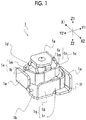
- Fig. 1 is a perspective view showing an outline of the pressure contact type connector 1 according to the first embodiment.
- Figs. 2A and 2B are views showing the pressure contact type connector 1 according to the first embodiment,
- Fig. 2A is a plan view showing the pressure contact type connector 1 when viewed from a Z1 direction side shown in Fig. 1
- Fig. 2B is a side view showing the pressure contact type connector 1 when viewed from a Y2 direction side shown in Fig. 1 .
- Figs. 3A and 3B are views showing the pressure contact type connector 1 according to the first embodiment,
- Fig. 3A is a sectional view showing a section taken along line A-A shown in Fig. 2A
- Fig. 3B is a sectional view showing a section taken along line B-B shown in Fig. 2A .
- the pressure contact type connector 1 is formed of a metal plate, which includes an L-shaped portion 1n which includes an upper plate portion 1k extending along a vertical direction (Z1-Z1 direction) and having a bent tip and an intermediate plate portion 1m connected to the lower side of the upper plate portion 1k and extending along a first direction (X1-X2 direction and one direction with respect to the upper plate portion 1k), and an L-shaped portion 1q which includes a lower plate portion 1p extending along the vertical direction and having a bent tip and an intermediate plate portion 1r connected to the upper side of the lower plate portion 1p and extending along a second direction (Y1-Y2 direction and one direction with respect to the lower plate portion 1p) in a horizontal direction.
- L-shaped portion 1n which includes an upper plate portion 1k extending along a vertical direction (Z1-Z1 direction) and having a bent tip and an intermediate plate portion 1m connected to the lower side of the upper plate portion 1k and extending along a first direction (X1-X2 direction and one
- the pressure contact type connector 1 includes an upper flat plate portion 1a which is formed by bending the upper plate portion 1k so as to extend along the other direction (second direction) which is the horizontal direction and is orthogonal to the first direction (one direction with respect to the upper plate portion 1k), and a lower flat plate portion 1b which is formed by bending the lower plate portion 1p so as to extend along the other direction (first direction) which is the horizontal direction and is orthogonal to the second direction (one direction with respect to the lower plate portion 1p).
- the pressure contact type connector 1 includes the upper flat plate portion 1a which extends in a flat plate shape along the horizontal direction including the X1-X2 direction and the Y1-Y2 direction, and the lower flat plate portion 1b which extends in a flat plate shape along the horizontal direction and is disposed below the upper flat plate portion 1a.
- the upper flat plate portion 1a and the lower flat plate portion 1b are disposed so that the upper flat plate portion 1a overlaps with the lower flat plate portion 1b in the vicinity of the center portion of the lower flat plate portion 1b when the pressure contact type connector 1 is viewed from above (Z1 direction side) in a plan view.
- a first spring portion 1c or a second spring portion 1d is formed by bending the intermediate plate portions 1m and 1r of a metal plate having the L-shaped portions 1n and 1q so as to be wound around a virtual center line which is set along the vertical direction, and the intermediate plate portion 1m extending from the upper plate portion 1k and the intermediate plate portion 1r from the lower plate portion 1p are integrally formed so as to be connected to each other.
- the intermediate plate portion 1m extending from the upper plate portion 1k and the intermediate plate portion 1r extending from the lower plate portion 1p are formed so as to be bent and wound around the virtual center line set along the vertical direction, and are connected to each other so as to be integrally formed.
- the pressure contact type connector 1 includes the first spring portion 1c which connects one end portion (Y1 direction side end portion) of the upper flat plate portion 1a and one end portion (X1 direction side end portion) of the lower flat plate portion 1b and has elasticity in the vertical direction, and the second spring portion 1d which extends from the other end portion (X2 direction side end) of the lower flat plate portion 1b toward the upper flat plate portion 1a, has elasticity in the vertical direction, and applies a resilient force to the upper flat plate portion 1a.
- the second spring portion 1d extends upward from the other end portion of the lower flat plate portion 1b and is not connected to the upper flat plate portion 1a.
- the second spring portion 1d may be formed so that the second spring portion 1d extends downward toward the lower flat plate portion 1b from the other end portion (Y2 direction side end portion) of the upper flat plate portion 1a and is not connected to the lower flat plate portion 1b, or may be formed so that the second spring portion 1d is connected to the lower flat plate portion 1b.
- the first spring portion 1c and the second spring portion 1d are wound in the same direction about the upper flat plate portion 1a, and extends so that the spring portions 1c and 1d do not interfere with each other when being compressed and extended in the vertical direction.
- the first spring portion 1c and the second spring portion 1d may come into slide-contact with each other when being compressed and extended in the vertical direction, and may be positioned so that the operations in the vertical direction are not hindered.
- an auxiliary upper flat plate portion 1h is disposed below the upper flat plate portion 1a, the upper flat plate portion 1a extends from the first spring portion 1c, the auxiliary upper flat plate portion 1h extends from the second spring portion 1d, and the upper flat plate portion 1a is disposed above the auxiliary upper flat plate portion 1h.
- the upper flat plate portion 1a and the auxiliary upper flat plate portion 1h are disposed so as to be separated from each other in the vertical direction in a contactable manner.
- the end portion of the upper side (Z1 direction side) of the second spring portion 1d is connected to the other end portion (Y2 direction side end portion) of the auxiliary upper flat plate portion 1h.
- the first spring portion 1c is formed so as to be bent with respect to the upper flat plate portion 1a and the lower flat plate portion 1b, and the first spring portion 1c protrudes upward from the one end portion (a position near the Y1 direction on the X1 direction side) of the lower flat plate portion 1b and is bent so as to be wound at the upper side of the lower flat plate portion 1b.
- the second spring portion 1d may be formed so as to be bent with respect to at least one of the upper flat plate portion 1a and the lower flat plate portion 1b, and in the first embodiment, the second spring portion 1d is formed so as to be bent with respect to the upper flat plate portion 1a and the lower flat plate portion 1b, protrudes from one (a position near the Y2 direction on the X2 direction side) of the other end portion of the auxiliary upper flat plate portion 1h and the other end portion of the lower flat plate portion 1b toward the other, and is bent so as to be wound at the upper side of the lower flat plate portion 1b.
- the first spring portion 1c and the second spring portion 1d are formed so that a width dimension W of a material in the vertical direction is larger than a thickness dimension T in the horizontal direction, and the width dimension W in the vertical direction of each of the first spring portion 1c and the second spring portion 1d decreases from the lower side toward the upper side in the entirety thereof.
- the width dimensions W in the vertical direction of the first spring portion 1c are different from one another according to the location.
- W11, W12, W13, and W14 are arranged in a location order close to the lower side (lower flat plate portion 1b), W11, W12, W13, and W14 are positioned in this order, and a magnitude relationship of W11 W12 W13 W14 is satisfied.
- the width dimensions W in the vertical direction are different from one another according to the location.
- stopper portions 1e which are formed to protrude upward are connected to the lower flat plate portion 1b at locations of noninterference with the first spring portion 1c and the second spring portion 1d.
- the stopper portion 1e is provided outside the first spring portion 1c and the second spring portion 1d, and in Figs. 2A and 2B , the stopper portions 1e are provided at the position near the X2 direction at the Y1 direction side end portion of the lower flat plate portion 1b, and at the position near the X1 direction at the Y2 direction side end portion.
- a height dimension H of each of the stopper portions 1e is the same as a height dimension h of each of the base portions 1f of the first spring portion 1c and the second spring portion 1d on the lower flat plate portion 1b.
- the height dimension H is the same as the height dimension h.
- the height dimension H may be equal to or more than the height dimension h, or may be equal to or more than the width dimension in the vertical direction.
- FIGS. 4A and 4B are schematic views for explaining the operation of the pressure contact type connector 1 according to the first embodiment
- Fig. 4A is a schematic sectional view showing an initial state of the pressure contact type connector 1
- Fig. 4B is a schematic sectional view showing the operation state of the pressure contact type connector 1.
- the pressure contact type connector 1 When the pressure contact type connector 1 is actually used, as shown in Figs. 4A and 4B , the pressure contact type connector 1 is used for connection between a wiring pattern PT1 on a circuit substrate of a mounted electric device and a wiring pattern PT2 of a different circuit substrate, or the like.
- a case where the pressure contact type connector 1 is disposed on the wiring pattern PT1 and the wiring pattern PT2 is disposed so as to overlap the pressure contact type connector 1 is described.
- the present invention is not limited to this.
- the pressure contact type connector 1 disposed on the wiring pattern PT1 is disposed so that the lower flat plate portion 1b comes into contact with the wiring pattern PT1, and the pressure contact type connector 1 and the wiring pattern PT1 are electrically connected to each other.
- the upper flat plate portion 1a of the pressure contact type connector 1 protrudes upward by elastic forces of the first spring portion 1c and the second spring portion 1d.
- the upper flat plate portion 1a and the auxiliary upper flat plate portion 1h are separated from each other.
- the upper flat plate portion 1a and the auxiliary upper flat plate portion 1h come into contact with each other, and in a state where the second spring portion 1d assists the first spring portion 1c, the first spring portion 1c and the second spring portion 1d are bent downward (to the Z2 direction).
- the pressure contact type connector 1 and the wiring pattern PT2 come into pressure-contact with each other, and thus, the pressure contact type connector 1 and the wiring pattern PT2 are electrically and stably connected to each other. That is, the wiring substrate including the wiring pattern PT1 and the wiring substrate including the wiring pattern PT2 are electrically connected to each other via the pressure contact type connector 1.
- the pressure contact type connector 1 of the first embodiment includes: the upper flat plate portion 1a which extends in a flat plate shape along the horizontal direction; the lower flat plate portion 1b which extends in a flat plate shape along the horizontal direction and is disposed below the upper flat plate portion 1a; the first spring portion 1c which connects the one end portion of the upper flat plate portion 1a and the one end portion of the lower flat plate portion 1b and has elasticity in the vertical direction; and a second spring portion 1d which extends from the other end portion of the lower flat plate portion 1b toward the upper flat plate portion 1a, includes elasticity in the vertical direction, and is configured to apply a resilient force to the upper flat plate portion 1a, in which the first spring portion 1c and the second spring portion 1d are wound in the same direction about the upper flat plate portion 1a when viewed from above in a plan view, and extend so that the first spring portion and the second spring portion do not interfere with each other when the spring portions are compressed and extended in the vertical direction, the first spring portion 1c is formed so as to be bent with
- the first spring portion 1c and the second spring portion 1d are formed so that the thickness direction of the first spring portion 1c and the thickness direction of the second spring portion 1d are the horizontal directions, and thus, a reduction in the size of the pressure contact type connector in the horizontal direction is achieved.
- the pressure contact type connector capable of having a reduced mounting area and obtaining a large elastic force.
- the upper flat plate portion 1a may be formed by bending the upper plate portion 1k of a metal plate having the L-shaped portion 1n, which includes the upper plate portion 1k extending along the vertical direction and the intermediate plate portion 1m connected to the lower side of the upper plate portion 1k and extending in one direction in the horizontal direction, so as to extend along the other direction which is the horizontal direction and is orthogonal to the one direction, and the first spring portion 1c or the second spring portion 1d may be formed by bending the intermediate plate portion 1m of a metal plate having the L-shaped portion 1n so as to be wound around a virtual center line which is set along the vertical direction.
- the upper plate portion 1k of a metal plate having the L-shaped portion 1n extending along the one direction in the horizontal direction is formed so as to be bent to extend along the other direction in the horizontal direction, and thus, it is possible to easily configure the upper flat plate portion 1a by bending it once.
- the lower flat plate portion 1b may be formed by bending the lower plate portion 1p of a metal plate having the L-shaped portion 1q, which includes the lower plate portion 1p extending along the vertical direction and the intermediate plate portion 1r connected to the upper side of the lower plate portion 1p and extending in one direction in the horizontal direction, so as to extend along the other direction which is the horizontal direction and is orthogonal to the one direction, and the first spring portion 1c or the second spring portion 1d may be formed by bending the intermediate plate portion 1r of a metal plate having the L-shaped portion 1q so as to be wound around a virtual center line which is set along the vertical direction.
- the lower plate portion 1p of a metal plate having the L-shaped portion 1q extending along the one direction in the horizontal direction is formed so as to be bent to extend along the other direction in the horizontal direction, and thus, it is possible to easily configure the lower flat plate portion 1b by bending it once.
- the first spring portion 1c may protrude upward from the one end portion of the lower flat plate portion 1b and may be bent so as to be wound at the upper side of the lower flat plate portion 1b
- the second spring portion 1d may protrude from the other end portion of the lower flat plate portion 1b toward the upper flat plate portion 1a, and may be bent so as to be wound at the upper side of the lower flat plate portion 1b.
- the lower flat plate portion 1b does not protrude from the first spring portion 1c and the second spring portion 1d in at least the one end portion (X1 direction side end portion) of the lower flat plate portion 1b and the other end portion (X2 direction side end portion) of the lower flat plate portion 1b, it is possible to decrease the mounting area.
- the first embodiment also in the Y1 direction side end portion and the Y2 direction side end portion of the lower flat plate portion 1b, since the lower flat plate portion 1b does not protrude outside from the first spring portion 1c and the second spring portion 1d, it is possible to further decrease the mounting area.
- the stopper portion 1e which is formed to protrude upward at a location of noninterference with the first spring portion 1c and the second spring portion 1d, may be connected to the lower flat plate portion 1b, and the height dimension H of the stopper portion 1e may be the same as the height dimension h of the base portion 1f of each of the first spring portion 1c and the second spring portion 1d on the lower flat plate portion 1b.
- the height dimension H of the stopper portion 1e is the same as the height dimension h of the base portion 1f of each of the first spring portion 1c and the second spring portion 1d on the lower flat plate portion 1b, it is possible to more securely prevent the first spring portion 1c and the second spring portion 1d from being plastically deformed.
- the stopper portion 1e may be provided outside the first spring portion 1c and the second spring portion 1d.
- the stopper portion 1e is provided outside the first spring portion 1c and the second spring portion 1d, it is possible to prevent a finger or the like from coming into direct-contact with the first spring portion 1c and the second spring portion 1d from the side. Therefore, it is possible to prevent the first spring portion 1c and the second spring portion 1d from being damaged. Moreover, when the first spring portion 1c and the second spring portion 1d extend and contract in the vertical direction, the stopper can function as a guide.
- the width dimension in the vertical direction of each of the first spring portion 1c and the second spring portion 1d may decrease from the lower side toward the upper side in the entirety thereof.
- the width dimension W in the vertical direction of each of the first spring portion 1c and the second spring portion 1d decreases from the lower side toward the upper side, it is possible to obtain an elastic force required for a stable electrical connection, and it is possible to lengthen strokes of (to easily bent) the first spring portion 1c and the second spring portion 1d.
- the width dimension may decrease from the lower side toward the upper side in the entirety thereof, and the width may partially increase.
- the second spring portion 1d may be connected to the other end portion of the lower flat plate portion 1b, and the auxiliary upper flat plate portion 1h extending from the second spring portion 1d may be provided on the lower side of the upper flat plate portion 1a.
- the upper flat plate portion 1a is configured to be disposed to overlap the auxiliary upper flat plate portion 1h, and thus, the pressure applied to the upper flat plate portion 1a is equally applied to the first spring portion 1c and the second spring portion 1d. Therefore, when the first spring portion 1c and the second spring portion 1d are pressed, the first spring portion 1c and the second spring portion 1d are not easily inclined, a predetermined elastic force can be obtained, and disadvantages such as deformation due to inclination do not easily occur.
- the upper flat plate portion 1a and the auxiliary upper flat plate portion 1h may be disposed so as to be separated from each other in the vertical direction in a contactable manner.
- the upper flat plate portion 1a and the auxiliary upper flat plate portion 1h are disposed so as to be separated from each other, when a surface treatment such as plating is performed after the shape of the pressure contact type connector 1 is formed, the surface treatment is also performed on the lower surface of the upper flat plate portion 1a and the upper surface of the auxiliary upper flat plate portion 1h, and thus, it is possible to prevent corrosion.
- the upper flat plate portion 1a is not easily inclined when being pressed and can easily move along the vertical direction.
- Fig. 5 is a flow chart showing a process of the manufacturing method MP of the pressure contact type connector 1 according to the first embodiment.
- the manufacturing method MP includes a punching step MP1, a first winding step MP2, a second winding step MP3, a third bending step MP4, a second bending step MP5, and a first bending step MP6. As shown in Fig. 5 , first, the punching step MP1 is performed.
- a punched body 5 (not shown), which includes the lower flat plate portion 1b, the first spring portion 1c extending from the one end portion of the lower flat plate portion 1b integrally with the upper flat plate portion 1a, and the second spring portion 1d extending from the other end portion of the lower flat plate portion 1b, is formed in an integral flat plate shape from one metal plate.
- the first winding step MP2 is performed.
- the punched body 5 is formed so as to be bent and wound the first spring portion 1c.
- the second winding step MP3 is performed.
- the punched body 5 is formed so as to be bent to wind the second spring portion 1d.
- the second winding step MP3 may be performed after the punching step MP1, and thereafter, the first winding step MP2 may be performed.
- the third bending step MP4 is performed.
- the punched body 5 is formed so as to be bent to extend the stopper portion 1e upward.
- the second bending step MP5 is performed.
- the second spring portion 1d is bent so as to stand upright with respect to the lower flat plate portion 1b.
- the first bending step MP6 is performed.
- the first spring portion 1c stands upright with respect to the lower flat plate portion 1b so that the first spring portion 1c does not interfere with the second spring portion 1d.
- the pressure contact type connector 1 is completed.
- the manufacturing process is described in which the third bending step MP4 is performed after the first winding step MP2 and the second winding step MP3.
- the second bending step MP5 and the first bending step MP6 may be performed after the first winding step MP2 and the second winding step MP3, and thereafter, the third bending step MP4 may be performed.
- the upper flat plate portion 1a is formed at the first winding step MP2, and the auxiliary upper flat plate portion 1h is formed at the second winding step MP3.
- the manufacturing method MP of the pressure contact type connector 1 of the first embodiment includes: the punching step MP1 of forming the punched body 5, which includes the lower flat plate portion 1b, the first spring portion 1c extending from one end portion of the lower flat plate portion 1b integrally with the upper flat plate portion 1a, and the second spring portion 1d extending from the other end portion of the lower flat plate portion 1b opposing the one end portion of the lower flat plate portion 1b while interposing the lower flat plate portion 1b, in an integral flat plate shape from one metal plate; the first winding step MP2 of bendingly forming the first spring portion 1c so as to be wound after the punching step MP1; the second winding step MP3 of bendingly forming the second spring portion 1d so as to be wound after the punching step MP1; the second bending step MP5 of bending the second spring portion 1d so as to stand upright with respect to the lower flat plate portion 1b after the second winding step MP3; and the first bending step MP6 of bending the first spring portion 1c so as
- the integrated intermediate portions 1m and 1r are bent three times by approximately 90 , and are formed within a range of approximately 270 in a plan view.
- the intermediate portions may be formed in a spiral shape in which arcs are formed, and the formation range may be 90 or more, and preferably, may be 180 or more.
- Figs. 6A and 6B are views showing the pressure contact type connector 2 according to the second embodiment
- Fig. 6A is a perspective view showing an outline of the pressure contact type connector 2
- Fig. 6B is a perspective view showing the pressure contact type connector 2 when viewed from the X1 direction side shown in Fig. 6A
- Figs. 7A and 7B are views showing the pressure contact type connector 2 according to the second embodiment
- Fig. 7A is a plan view showing the pressure contact type connector 2 when viewed from the Z1 direction side shown in Figs. 6A and 6B
- FIG. 7B is a side view showing the pressure contact type connector 2 when viewed from the Y2 direction side shown in Figs. 6A and 6B .
- Fig. 8 is a sectional view showing a section of the pressure contact type connector 2 according to the second embodiment taken along line C-C shown in Figs. 7A and 7B .
- the pressure contact type connector 2 includes: an upper flat plate portion 2a which extends along the horizontal direction including the X1-X2 direction and the Y1-Y2 direction and has a flat plate shape; a lower flat plate portion 2b which extends along the horizontal direction, has a flat plate shape and is disposed below the upper flat plate portion 2a; and a spring portion 2c which connects one end portion (end portion of the X2 direction side) of the upper flat plate portion 2a and one end portion (end portion of the X1 direction side) of the lower flat plate portion 2b and has elasticity in the vertical direction (Z1-Z2 direction).
- the pressure contact type connector 2 is formed of a metal plate, which includes an L-shaped portion 2f which includes an upper plate portion 2d extending along the vertical direction and having a bent tip and an intermediate plate portion 2e connected to the lower side (Z2 direction side) of the upper plate portion 2d and extending along one direction (Y1-Y2 direction) in the horizontal direction, and an L-shaped portion 2m which includes a lower plate portion 2g extending along the vertical direction and an intermediate plate portion 2n connected to the upper side (Z1 direction side) of the lower plate portion 2g and extending along one direction in the horizontal direction.
- the upper flat plate portion 2a is formed by bending the upper plate portion 2d so as to extend along the other direction (X1-X2 direction) which is the horizontal direction and is orthogonal to the one direction
- the lower flat plate portion 2b is formed by bending the lower plate portion 2g so as to extend along the other direction which is the horizontal direction and is orthogonal to the one direction.
- the spring portion 2c is formed so as to be bent with respect to the upper flat plate portion 2a and the lower flat plate portion 2b, and is formed by bending the intermediate plate portions 2e and 2n of a metal plate having the L-shaped portions 2f and 2m so as to be wound around the virtual center line set along the vertical direction and by connecting the intermediate plate portion 2e extending downward from the upper plate portion 2d and the intermediate plate portion 2n extending upward from the lower plate portion 2g.
- the width dimension W of a material in the vertical direction of the spring portion 2c is larger than the thickness dimension T in the horizontal direction.
- the width dimension W in the vertical direction of the spring portion 2c decreases from the lower side toward the upper side in the entirety thereof.
- the width dimensions W in the vertical direction of the spring portion 2c are different from one another according to the location.
- stopper portions 2h which are formed to protrude upward are connected to the lower flat plate portion 2b at locations of noninterference with the spring portion 2c.
- the stopper portions 2h are provided outside the spring portions 2c when viewed from above in a plan view.
- the stopper portions 2h are formed so as to protrude upward from the end portions of the X2 direction side, the Y1 direction side, and the Y2 directions side of the lower flat plate portion 2b.
- a height dimension h of each of the stopper portions 2h is the same as a height dimension H of a base portion 2k of each of the spring portions 2c connected to the lower flat plate portion 2b.
- the height dimension h is the same as the height dimension H.
- the height dimension h of the stopper portion 2h is equal to or more than the height dimension H of the base portion 2k or equal to or more than the width dimension in the vertical direction of the spring portion 2c.
- Figs. 9A and 9B are schematic views for explaining the operation of the pressure contact type connector 2 according to the second embodiment
- Fig. 9A is a schematic sectional view showing an initial state of the pressure contact type connector 2
- Fig. 9B is a schematic sectional view showing the operation state of the pressure contact type connector 1.
- the pressure contact type connector 1 is used for connection between the wiring pattern PT1 on a circuit substrate of the mounted electric device and the wiring pattern PT2 of a different circuit substrate, or the like.
- the pressure contact type connector 2 is disposed on the wiring pattern PT1 and the wiring pattern PT2 is disposed so as to overlap the pressure contact type connector 2 is described.
- the present invention is not limited to this.
- the pressure contact type connector 2 disposed on the wiring pattern PT1 is disposed so that the lower flat plate portion 2b comes into contact with the wiring pattern PT1, and the pressure contact type connector 2 and the wiring pattern PT2 are electrically connected to each other.
- the upper flat plate portion 2a of the pressure contact type connector 1 protrudes upward by the elastic force of the spring portion 2c.
- the pressure contact type connector 2 When the wiring pattern PT2 is disposed on the pressure contact type connector 2, as shown in Fig. 9B , the pressure contact type connector 2 is bent downward (Z2 direction). In this case, the pressure contact type connector 2 and the wiring pattern PT2 come into pressure-contact with each other, and thus, the pressure contact type connector 2 and the wiring pattern PT2 are electrically and stably connected to each other. That is, the wiring substrate including the wiring pattern PT1 and the wiring substrate including the wiring pattern PT2 are electrically connected to each other via the pressure contact type connector 2.
- the pressure contact type connector 2 of the second embodiment includes: the upper flat plate portion 2a which extends in a flat plate shape along the horizontal direction; the lower flat plate portion 2b which extends in a flat plate shape along the horizontal direction and is disposed below the upper flat plate portion 2a; and the spring portion 2c which connects one end portion of the upper flat plate portion 2a and one end portion of the lower flat plate portion 2b and has elasticity in the vertical direction, in which the spring portion 2c is formed so as to be bent with respect to the upper flat plate portion 2a and the lower flat plate portion 2b so that the width dimension in the vertical direction is larger than the thickness dimension in the horizontal direction.
- the spring portion 2c is formed so that the thickness direction of the spring portion 2c is the horizontal direction, and thus, a reduction in the size of the pressure contact type connector in the horizontal direction is achieved.
- the spring portion 2c when viewed from the side, since it is possible to increase the width dimension of the spring portion 2c with respect to the directions in which the spring portion 2c are wound, it is possible to obtain a large elastic force. Accordingly, it is possible to provide the pressure contact type connector capable of having a reduced mounting area and obtaining a large elastic force.
- the upper flat plate portion 2a may be formed by bending the upper plate portion 2d of a metal plate having the L-shaped portion 2f, which includes the upper plate portion 2d extending along the vertical direction and an intermediate plate portion 2e connected to the lower side of the upper plate portion 2d and extending in one direction in the horizontal direction, to extend along the other direction which is the horizontal direction and is orthogonal to the one direction, and the spring portion 2c may be formed by bending the intermediate plate portion 2e of a metal plate having the L-shaped portion 2f so as to be wound around a virtual center line which is set along the vertical direction.
- the upper plate portion 2d of a metal plate having the L-shaped portion 2f extending along the one direction in the horizontal direction is formed so as to be bent to extend along the other direction in the horizontal direction, and thus, it is possible to easily configure the upper flat plate portion 2a by bending it once.
- the lower flat plate portion 2b may be formed by bending the lower plate portion 2g of a metal plate having the L-shaped portion 2m, which includes the lower plate portion 2g extending along the vertical direction and the intermediate plate portion 2n connected to the upper side of the lower plate portion 2g and extending in one direction in the horizontal direction, so as to extend along the other direction which is the horizontal direction and is orthogonal to the one direction, and the spring portion 2c may be formed by bending the intermediate plate portion 2n of a metal plate having the L-shaped portion 2m so as to be wound around a virtual center line which is set along the vertical direction.
- the lower plate portion 2g of a metal plate having the L-shaped portion 2m extending along the one direction in the horizontal direction is formed so as to be bent to extend along the other direction in the horizontal direction, and thus, it is possible to easily configure the lower flat plate portion 2b by bending it once.
- the stopper portion 2h which is formed to protrude upward at a location of noninterference with the spring portion 2c, may be connected to the lower flat plate portion 2b.
- the stopper portion 2h is connected to the lower flat plate portion 2b, it is possible to limit a displacement amount in the vertical direction, and it possible to prevent the spring portion 2c from being damaged.
- the height dimension of the stopper portion 2h may be equal to or more than the height dimension of the base portion 2k of the spring portion 2c connected to the lower flat plate portion 2b.
- the height dimension of the stopper portion 2h is equal to or more than the height dimension of the base portion 2k, it is possible to limit the displacement amount in the vertical direction within a range in which the spring portion 2c is elastically deformed, and it is possible to securely prevent the spring portion 2c from being damaged.
- the stopper portion 2h may be provided outside the spring portion 2c.
- the stopper portion 2h is provided outside the spring portion 2c, it is possible to prevent a finger or the like from coming into contact with the spring portions from the side and to prevent the spring portion 2c being damaged.
- the stopper portion 2h can function as a guide.
- the width dimension in the vertical direction of the spring portion 2c may decrease from the lower side toward the upper side in the entirety thereof.
- the width dimension in the vertical direction of the spring portion 2c decreases from the lower side toward the upper side, it is possible to obtain an elastic force required for a stable electrical connection, and it is possible to lengthen the stroke of the spring portion 2c.
- the width dimension may decrease from the lower side toward the upper side in the entirety thereof, and the width may partially increase.
- Fig. 10 is a flow chart showing a process of the manufacturing method mp of the pressure contact type connector 2 according to the second embodiment.
- the manufacturing method mp includes a punching step mp1, an upper flat plate portion forming step mp2, a lower flat plate portion forming step mp3, and a spring portion forming step mp4. As shown in Fig. 10 , first, the punching step mp1 is performed.
- a crank-shaped punched portion 6 (not shown), which includes the intermediate plate portion 2e extending in the horizontal direction, the upper plate portion 2d connected upward to the one end portion of the intermediate plate portion 2e, and the lower plate portion 2g connected downward to the other end portion of the intermediate plate portion 2e, is formed in an integral flat plate shape from one metal plate.
- the upper flat plate portion forming step mp2 is performed.
- the upper plate portion 2d of the crank-shaped punched portion 6 is bent to form the upper flat plate portion 2a.
- the lower flat plate portion forming step mp3 is performed.
- the lower plate portion 2g of the crank-shaped punched portion 6 is bent to form the lower flat plate portion 2b.
- the lower flat plate portion forming step mp3 may be performed after the punching step mp1, and thereafter, the upper flat plate portion forming step mp2 may be performed.
- the spring portion forming step mp4 is performed.
- the intermediate plate portion 2e of the crank-shaped punched portion 6 is bent so as to be wound to form the spring portion 2c. According to the manufacturing processes, the pressure contact type connector 2 is completed.
- the manufacturing method mp of the pressure contact type connector 2 of the second embodiment includes: the punching step mp1 of forming the crank-shaped punched portion 6, which includes the integral intermediate plate portions 2e and 2m extending in the horizontal direction, the upper plate portion 2d connected upward to the one end portion of the intermediate plate portions 2e and 2m, and the lower plate portion 2g connected downward to the other end portion of the intermediate plate portion 2e, in an integral flat plate shape from one metal plate; the upper flat plate portion forming step mp2 of forming the upper flat plate portion 2a by bending the upper plate portion 2d after the punching step mp1; the lower flat plate portion forming step mp3 of forming the lower flat plate portion 2b by bending the lower plate portion 2g after the punching step mp1; and the spring portion forming step mp4 of forming the spring portion 2c by bending the intermediate plate portions 2e and 2m so as to be wound after the punching step mp1.
- FIG. 11A and 11B used for the explanations are views showing the pressure contact type connector 1 according to a fourth embodiment
- Fig. 11A is a plan view showing an outline of the pressure contact type connector 1
- Fig. 11B is a sectional view showing a section taken along line D-D shown in Fig. 11A
- Figs. 12A and 12B are views showing the pressure contact type connector 1 according to a fifth embodiment
- Fig. 12A is a perspective view showing an outline of the pressure contact type connector 1
- Fig. 12B is an exploded perspective view showing a configuration of the pressure contact type connector 1.
- the upper flat plate portion 1a includes the upper flat plate portion 1a and the auxiliary upper flat plate portion 1h.
- the upper flat plate portion 1a may be configured to include only the upper flat plate portion 1a according to the first embodiment, and the lower surface of the upper flat plate portion 1a may be held by the tip portion of the upper side of the second spring portion 1d.
- the stopper portion 1e is provided outside the first spring portion 1c and the second spring portion 1d.
- the stopper portion 1e may be provided inside the first spring portion 1c and the second spring portion 1d and below the upper flat plate portion 1a.
- the pressure contact type connector 1 is a single body.
- the periphery of the pressure contact type connector 1 is covered by a protective cover 7. Since the protective cover 7 is provided, when a finger unintentionally comes into contact with the pressure contact type connector, the force in the horizontal direction is not easily transmitted to the first spring portion 1c and the second spring portion 1d, and it is possible to prevent the pressure contact type connector 1 from being damaged.
- the protective cover 7 since the protective cover 7 is guided along the outline of the pressure contact type connector 1, the protective cover is not easily inclined and easily moves in the vertical direction.
Applications Claiming Priority (3)
| Application Number | Priority Date | Filing Date | Title |
|---|---|---|---|
| JP2014107561 | 2014-05-23 | ||
| JP2014173577A JP6224551B2 (ja) | 2014-05-23 | 2014-08-28 | 圧接コネクタとその製造方法 |
| EP15168662.3A EP2947721B1 (fr) | 2014-05-23 | 2015-05-21 | Connecteur de type à contact à pression et son procédé de fabrication |
Related Parent Applications (2)
| Application Number | Title | Priority Date | Filing Date |
|---|---|---|---|
| EP15168662.3A Division EP2947721B1 (fr) | 2014-05-23 | 2015-05-21 | Connecteur de type à contact à pression et son procédé de fabrication |
| EP15168662.3A Division-Into EP2947721B1 (fr) | 2014-05-23 | 2015-05-21 | Connecteur de type à contact à pression et son procédé de fabrication |
Publications (2)
| Publication Number | Publication Date |
|---|---|
| EP3416245A1 true EP3416245A1 (fr) | 2018-12-19 |
| EP3416245B1 EP3416245B1 (fr) | 2021-08-25 |
Family
ID=53188966
Family Applications (2)
| Application Number | Title | Priority Date | Filing Date |
|---|---|---|---|
| EP15168662.3A Active EP2947721B1 (fr) | 2014-05-23 | 2015-05-21 | Connecteur de type à contact à pression et son procédé de fabrication |
| EP18185332.6A Active EP3416245B1 (fr) | 2014-05-23 | 2015-05-21 | Connecteur de type à contact à pression et son procédé de fabrication |
Family Applications Before (1)
| Application Number | Title | Priority Date | Filing Date |
|---|---|---|---|
| EP15168662.3A Active EP2947721B1 (fr) | 2014-05-23 | 2015-05-21 | Connecteur de type à contact à pression et son procédé de fabrication |
Country Status (6)
| Country | Link |
|---|---|
| US (4) | US9912090B2 (fr) |
| EP (2) | EP2947721B1 (fr) |
| JP (1) | JP6224551B2 (fr) |
| KR (4) | KR101737552B1 (fr) |
| CN (6) | CN108418023B (fr) |
| DE (2) | DE202015009612U1 (fr) |
Families Citing this family (25)
| Publication number | Priority date | Publication date | Assignee | Title |
|---|---|---|---|---|
| JP6224551B2 (ja) * | 2014-05-23 | 2017-11-01 | アルプス電気株式会社 | 圧接コネクタとその製造方法 |
| KR101644123B1 (ko) * | 2014-10-07 | 2016-07-29 | 조인셋 주식회사 | 탄성 전기접촉단자 |
| JP6214053B2 (ja) * | 2014-12-15 | 2017-10-18 | アルプス電気株式会社 | 圧接コネクタ |
| JP6500258B2 (ja) * | 2015-06-12 | 2019-04-17 | 北川工業株式会社 | 接触部材 |
| JP6584926B2 (ja) * | 2015-11-13 | 2019-10-02 | アルプスアルパイン株式会社 | 圧接コネクタ |
| JP2017091894A (ja) * | 2015-11-13 | 2017-05-25 | アルプス電気株式会社 | 圧接コネクタ |
| JP6483008B2 (ja) * | 2015-11-26 | 2019-03-13 | アルプスアルパイン株式会社 | 圧接コネクタ |
| JP6406645B2 (ja) * | 2015-12-10 | 2018-10-17 | アルプス電気株式会社 | 圧接コネクタ |
| JP2019096378A (ja) * | 2016-04-11 | 2019-06-20 | アルプスアルパイン株式会社 | 圧接コンタクト |
| JP6603170B2 (ja) * | 2016-04-25 | 2019-11-06 | ヒロセ電機株式会社 | 電気コネクタ |
| CN105938949B (zh) * | 2016-05-31 | 2020-04-21 | 深圳市信维通信股份有限公司 | 一种矩形抗冲击弹片连接器 |
| TWI649923B (zh) * | 2016-06-17 | 2019-02-01 | 日商阿爾普士電氣股份有限公司 | Crimp type joint and manufacturing method thereof |
| TWD183595S (zh) * | 2016-09-29 | 2017-06-11 | 進聯工業股份有限公司 | 導線連接器之座體 |
| JP6778596B2 (ja) | 2016-11-30 | 2020-11-04 | アルプスアルパイン株式会社 | 圧接コネクタおよびその製造方法 |
| CN108232524A (zh) * | 2016-12-14 | 2018-06-29 | 上海徕木电子股份有限公司 | 一种超微型塔形短路弹片 |
| AU2017386174B2 (en) * | 2016-12-26 | 2019-12-19 | Huawei Technologies Co., Ltd. | Elastic piece and terminal |
| JP6873424B2 (ja) * | 2017-01-11 | 2021-05-19 | 日本圧着端子製造株式会社 | 基板対基板コネクタ |
| JP6732954B2 (ja) * | 2017-01-13 | 2020-07-29 | アルプスアルパイン株式会社 | 圧接コネクタ |
| JP6829082B2 (ja) * | 2017-01-13 | 2021-02-10 | アルプスアルパイン株式会社 | 圧接コネクタ |
| JP2018147724A (ja) * | 2017-03-06 | 2018-09-20 | アルプス電気株式会社 | 圧接コネクタ |
| KR102318009B1 (ko) | 2017-06-09 | 2021-10-28 | 삼성전자주식회사 | 접촉 장치 및 이를 포함하는 전자 장치 |
| AT520449B1 (de) | 2017-09-27 | 2019-04-15 | Nrg X Charging Systems Gmbh | Komponente für eine Ladeeinrichtung und Ladeeinrichtung hiermit |
| JP6903331B2 (ja) * | 2018-03-29 | 2021-07-14 | 北川工業株式会社 | コンタクト及びその製造方法 |
| CN110350347B (zh) * | 2018-04-03 | 2022-08-19 | 富士康(昆山)电脑接插件有限公司 | 压接连接器 |
| JP7240901B2 (ja) * | 2019-02-28 | 2023-03-16 | アルプスアルパイン株式会社 | 圧接コネクタ |
Citations (5)
| Publication number | Priority date | Publication date | Assignee | Title |
|---|---|---|---|---|
| JP2010118256A (ja) | 2008-11-13 | 2010-05-27 | Advanced Systems Japan Inc | スパイラルコンタクタ、及びその製造方法 |
| WO2010122612A1 (fr) * | 2009-04-24 | 2010-10-28 | 株式会社アドバンストシステムズジャパン | Contacteur spiral et son procédé de fabrication |
| JP2011009142A (ja) * | 2009-06-29 | 2011-01-13 | Advanced Systems Japan Inc | スパイラルコンタクタおよびその製造方法 |
| EP2403070A1 (fr) * | 2010-07-03 | 2012-01-04 | Amphenol-Tuchel Electronics GmbH | Contact à ressort |
| EP2557634A1 (fr) * | 2011-08-09 | 2013-02-13 | Yokowo Co., Ltd | Connecteur |
Family Cites Families (31)
| Publication number | Priority date | Publication date | Assignee | Title |
|---|---|---|---|---|
| US4652075A (en) * | 1985-01-30 | 1987-03-24 | Billette De Villemeur Philippe | Resilient removable electrical terminal-connector |
| FR2658365B1 (fr) | 1990-02-14 | 1992-04-24 | Alcatel Radiotelephone | Ressort du type conique pour contact electrique. |
| US5184962A (en) * | 1991-12-05 | 1993-02-09 | Burndy Corporation | Electrical spring contact |
| US5655913A (en) * | 1995-09-26 | 1997-08-12 | Motorola, Inc. | Electrical interconnect contact |
| JP2001267016A (ja) * | 2000-03-21 | 2001-09-28 | Tyco Electronics Amp Kk | カードコネクタ用カバー及びそれを用いたカードコネクタ組立体 |
| TW488116B (en) * | 2000-03-31 | 2002-05-21 | Matsushita Electric Works Ltd | Receptacle for coaxial plug connector |
| JP3440243B2 (ja) * | 2000-09-26 | 2003-08-25 | 株式会社アドバンストシステムズジャパン | スパイラルコンタクタ |
| US20050245142A1 (en) * | 2004-05-03 | 2005-11-03 | January Kister | Sheet metal coil spring testing connector |
| KR100662339B1 (ko) | 2004-07-02 | 2007-01-02 | 엘지전자 주식회사 | 휴대용 전기 기기의 접속 단자 |
| JP4354889B2 (ja) * | 2004-09-02 | 2009-10-28 | アルプス電気株式会社 | コネクタ用基板 |
| US7393214B2 (en) | 2006-02-17 | 2008-07-01 | Centipede Systems, Inc. | High performance electrical connector |
| JP4936874B2 (ja) * | 2006-12-19 | 2012-05-23 | モレックス インコーポレイテド | コネクタ端子及びコネクタ |
| JP2008281519A (ja) | 2007-05-14 | 2008-11-20 | Alps Electric Co Ltd | プローブカードおよびその製造方法 |
| JP2010056048A (ja) * | 2008-08-29 | 2010-03-11 | Advanced Systems Japan Inc | スパイラルコンタクタ、及びその製造方法 |
| CN201289923Y (zh) * | 2008-09-28 | 2009-08-12 | Fci连接器新加坡有限公司 | 接触端子和电连接器 |
| JP2010257757A (ja) * | 2009-04-24 | 2010-11-11 | Advanced Systems Japan Inc | スパイラルコンタクタ |
| JP2011060694A (ja) * | 2009-09-14 | 2011-03-24 | Tyco Electronics Japan Kk | 電気コンタクト |
| JP5540718B2 (ja) * | 2010-01-15 | 2014-07-02 | オムロン株式会社 | 電気コネクタ、電子機器および導電接触方法 |
| EP2375500A1 (fr) * | 2010-03-04 | 2011-10-12 | Tyco Electronics Nederland B.V. | Élément de contact extensible pour connecteurs électriques |
| CN102195151A (zh) * | 2010-03-12 | 2011-09-21 | 鸿富锦精密工业(深圳)有限公司 | 弹片 |
| US8562359B2 (en) * | 2011-01-18 | 2013-10-22 | Tyco Electronics Corporation | Electrical contact for interconnect member |
| CN202308540U (zh) * | 2011-11-03 | 2012-07-04 | 蔡添庆 | 新型usb连接器 |
| JP2014071964A (ja) * | 2012-09-27 | 2014-04-21 | Fujitsu Component Ltd | コンタクト部材 |
| KR101473811B1 (ko) | 2012-11-23 | 2014-12-17 | 일진엘이디(주) | 와이어 본딩 장치용 세정 키트, 이를 포함하는 와이어 본딩 장치 및 이를 이용한 캐필러리 세정 방법 |
| JP2014173577A (ja) | 2013-03-13 | 2014-09-22 | Suzuki Motor Corp | 内燃機関の燃料噴射制御装置 |
| JP6005575B2 (ja) * | 2013-04-11 | 2016-10-12 | 日本航空電子工業株式会社 | コネクタ |
| CN203406443U (zh) * | 2013-07-24 | 2014-01-22 | 北大青鸟环宇消防设备股份有限公司 | 弹性压接供电结构 |
| DE202013103444U1 (de) * | 2013-07-31 | 2014-11-04 | Weidmüller Interface GmbH & Co. KG | Kontaktelement für eine Steckanordnung eines insbesondere außen geführten Bussystems |
| JP6108462B2 (ja) * | 2013-10-18 | 2017-04-05 | 日本航空電子工業株式会社 | コネクタ |
| JP6224551B2 (ja) * | 2014-05-23 | 2017-11-01 | アルプス電気株式会社 | 圧接コネクタとその製造方法 |
| WO2016056783A1 (fr) * | 2014-10-07 | 2016-04-14 | 조인셋 주식회사 | Borne de contact électrique élastique du type à montage en surface |
-
2014
- 2014-08-28 JP JP2014173577A patent/JP6224551B2/ja active Active
-
2015
- 2015-05-19 CN CN201810034409.3A patent/CN108418023B/zh active Active
- 2015-05-19 CN CN201810034410.6A patent/CN108054527B/zh active Active
- 2015-05-19 CN CN201510257309.3A patent/CN105098432B/zh active Active
- 2015-05-19 CN CN201810034315.6A patent/CN108054544A/zh active Pending
- 2015-05-19 CN CN201520325323.8U patent/CN204732575U/zh not_active Withdrawn - After Issue
- 2015-05-19 CN CN201810033378.XA patent/CN108054526B/zh active Active
- 2015-05-21 DE DE202015009612.3U patent/DE202015009612U1/de active Active
- 2015-05-21 KR KR1020150070841A patent/KR101737552B1/ko active IP Right Grant
- 2015-05-21 EP EP15168662.3A patent/EP2947721B1/fr active Active
- 2015-05-21 EP EP18185332.6A patent/EP3416245B1/fr active Active
- 2015-05-21 DE DE202015009642.5U patent/DE202015009642U1/de active Active
- 2015-05-22 US US14/719,986 patent/US9912090B2/en active Active
-
2017
- 2017-05-12 KR KR1020170059106A patent/KR101771880B1/ko active IP Right Grant
- 2017-05-12 KR KR1020170059109A patent/KR101849493B1/ko active IP Right Grant
- 2017-05-12 KR KR1020170059108A patent/KR101778493B1/ko active IP Right Grant
- 2017-08-17 US US15/679,490 patent/US10008801B2/en active Active
- 2017-08-17 US US15/679,647 patent/US9997855B2/en active Active
- 2017-08-17 US US15/679,535 patent/US10003147B2/en active Active
Patent Citations (5)
| Publication number | Priority date | Publication date | Assignee | Title |
|---|---|---|---|---|
| JP2010118256A (ja) | 2008-11-13 | 2010-05-27 | Advanced Systems Japan Inc | スパイラルコンタクタ、及びその製造方法 |
| WO2010122612A1 (fr) * | 2009-04-24 | 2010-10-28 | 株式会社アドバンストシステムズジャパン | Contacteur spiral et son procédé de fabrication |
| JP2011009142A (ja) * | 2009-06-29 | 2011-01-13 | Advanced Systems Japan Inc | スパイラルコンタクタおよびその製造方法 |
| EP2403070A1 (fr) * | 2010-07-03 | 2012-01-04 | Amphenol-Tuchel Electronics GmbH | Contact à ressort |
| EP2557634A1 (fr) * | 2011-08-09 | 2013-02-13 | Yokowo Co., Ltd | Connecteur |
Also Published As
Similar Documents
| Publication | Publication Date | Title |
|---|---|---|
| EP3416245A1 (fr) | Connecteur de type à contact à pression et son procédé de fabrication | |
| US9887480B2 (en) | Contact including deformation preventer for preventing deformation of connector support | |
| TWI686018B (zh) | 導電性元件、導電性元件用的板狀構件及導電性元件的製造方法 | |
| US9865939B2 (en) | Connecting element with a spring tab | |
| US20160120024A1 (en) | Linear Conductor Connection Terminal | |
| JP6379268B2 (ja) | 圧接コネクタ | |
| US20150269397A1 (en) | Card contact-making apparatus | |
| US20150278559A1 (en) | Card contact-making apparatus | |
| JP7240901B2 (ja) | 圧接コネクタ | |
| TWI615866B (zh) | 開關裝置及彈性接點之製造方法 |
Legal Events
| Date | Code | Title | Description |
|---|---|---|---|
| PUAI | Public reference made under article 153(3) epc to a published international application that has entered the european phase |
Free format text: ORIGINAL CODE: 0009012 |
|
| STAA | Information on the status of an ep patent application or granted ep patent |
Free format text: STATUS: THE APPLICATION HAS BEEN PUBLISHED |
|
| AC | Divisional application: reference to earlier application |
Ref document number: 2947721 Country of ref document: EP Kind code of ref document: P |
|
| AK | Designated contracting states |
Kind code of ref document: A1 Designated state(s): AL AT BE BG CH CY CZ DE DK EE ES FI FR GB GR HR HU IE IS IT LI LT LU LV MC MK MT NL NO PL PT RO RS SE SI SK SM TR |
|
| AX | Request for extension of the european patent |
Extension state: BA ME |
|
| RAP1 | Party data changed (applicant data changed or rights of an application transferred) |
Owner name: ALPS ALPINE CO., LTD. |
|
| STAA | Information on the status of an ep patent application or granted ep patent |
Free format text: STATUS: REQUEST FOR EXAMINATION WAS MADE |
|
| 17P | Request for examination filed |
Effective date: 20190618 |
|
| RBV | Designated contracting states (corrected) |
Designated state(s): AL AT BE BG CH CY CZ DE DK EE ES FI FR GB GR HR HU IE IS IT LI LT LU LV MC MK MT NL NO PL PT RO RS SE SI SK SM TR |
|
| STAA | Information on the status of an ep patent application or granted ep patent |
Free format text: STATUS: EXAMINATION IS IN PROGRESS |
|
| STAA | Information on the status of an ep patent application or granted ep patent |
Free format text: STATUS: EXAMINATION IS IN PROGRESS |
|
| 17Q | First examination report despatched |
Effective date: 20201103 |
|
| GRAP | Despatch of communication of intention to grant a patent |
Free format text: ORIGINAL CODE: EPIDOSNIGR1 |
|
| STAA | Information on the status of an ep patent application or granted ep patent |
Free format text: STATUS: GRANT OF PATENT IS INTENDED |
|
| INTG | Intention to grant announced |
Effective date: 20210408 |
|
| GRAS | Grant fee paid |
Free format text: ORIGINAL CODE: EPIDOSNIGR3 |
|
| GRAA | (expected) grant |
Free format text: ORIGINAL CODE: 0009210 |
|
| STAA | Information on the status of an ep patent application or granted ep patent |
Free format text: STATUS: THE PATENT HAS BEEN GRANTED |
|
| AC | Divisional application: reference to earlier application |
Ref document number: 2947721 Country of ref document: EP Kind code of ref document: P |
|
| AK | Designated contracting states |
Kind code of ref document: B1 Designated state(s): AL AT BE BG CH CY CZ DE DK EE ES FI FR GB GR HR HU IE IS IT LI LT LU LV MC MK MT NL NO PL PT RO RS SE SI SK SM TR |
|
| REG | Reference to a national code |
Ref country code: CH Ref legal event code: EP |
|
| REG | Reference to a national code |
Ref country code: IE Ref legal event code: FG4D Ref country code: AT Ref legal event code: REF Ref document number: 1424753 Country of ref document: AT Kind code of ref document: T Effective date: 20210915 |
|
| REG | Reference to a national code |
Ref country code: DE Ref legal event code: R096 Ref document number: 602015072778 Country of ref document: DE |
|
| REG | Reference to a national code |
Ref country code: LT Ref legal event code: MG9D |
|
| REG | Reference to a national code |
Ref country code: NL Ref legal event code: MP Effective date: 20210825 |
|
| REG | Reference to a national code |
Ref country code: AT Ref legal event code: MK05 Ref document number: 1424753 Country of ref document: AT Kind code of ref document: T Effective date: 20210825 |
|
| PG25 | Lapsed in a contracting state [announced via postgrant information from national office to epo] |
Ref country code: NO Free format text: LAPSE BECAUSE OF FAILURE TO SUBMIT A TRANSLATION OF THE DESCRIPTION OR TO PAY THE FEE WITHIN THE PRESCRIBED TIME-LIMIT Effective date: 20211125 Ref country code: PT Free format text: LAPSE BECAUSE OF FAILURE TO SUBMIT A TRANSLATION OF THE DESCRIPTION OR TO PAY THE FEE WITHIN THE PRESCRIBED TIME-LIMIT Effective date: 20211227 Ref country code: BG Free format text: LAPSE BECAUSE OF FAILURE TO SUBMIT A TRANSLATION OF THE DESCRIPTION OR TO PAY THE FEE WITHIN THE PRESCRIBED TIME-LIMIT Effective date: 20211125 Ref country code: AT Free format text: LAPSE BECAUSE OF FAILURE TO SUBMIT A TRANSLATION OF THE DESCRIPTION OR TO PAY THE FEE WITHIN THE PRESCRIBED TIME-LIMIT Effective date: 20210825 Ref country code: LT Free format text: LAPSE BECAUSE OF FAILURE TO SUBMIT A TRANSLATION OF THE DESCRIPTION OR TO PAY THE FEE WITHIN THE PRESCRIBED TIME-LIMIT Effective date: 20210825 Ref country code: RS Free format text: LAPSE BECAUSE OF FAILURE TO SUBMIT A TRANSLATION OF THE DESCRIPTION OR TO PAY THE FEE WITHIN THE PRESCRIBED TIME-LIMIT Effective date: 20210825 Ref country code: SE Free format text: LAPSE BECAUSE OF FAILURE TO SUBMIT A TRANSLATION OF THE DESCRIPTION OR TO PAY THE FEE WITHIN THE PRESCRIBED TIME-LIMIT Effective date: 20210825 Ref country code: HR Free format text: LAPSE BECAUSE OF FAILURE TO SUBMIT A TRANSLATION OF THE DESCRIPTION OR TO PAY THE FEE WITHIN THE PRESCRIBED TIME-LIMIT Effective date: 20210825 Ref country code: ES Free format text: LAPSE BECAUSE OF FAILURE TO SUBMIT A TRANSLATION OF THE DESCRIPTION OR TO PAY THE FEE WITHIN THE PRESCRIBED TIME-LIMIT Effective date: 20210825 Ref country code: FI Free format text: LAPSE BECAUSE OF FAILURE TO SUBMIT A TRANSLATION OF THE DESCRIPTION OR TO PAY THE FEE WITHIN THE PRESCRIBED TIME-LIMIT Effective date: 20210825 |
|
| PG25 | Lapsed in a contracting state [announced via postgrant information from national office to epo] |
Ref country code: PL Free format text: LAPSE BECAUSE OF FAILURE TO SUBMIT A TRANSLATION OF THE DESCRIPTION OR TO PAY THE FEE WITHIN THE PRESCRIBED TIME-LIMIT Effective date: 20210825 Ref country code: LV Free format text: LAPSE BECAUSE OF FAILURE TO SUBMIT A TRANSLATION OF THE DESCRIPTION OR TO PAY THE FEE WITHIN THE PRESCRIBED TIME-LIMIT Effective date: 20210825 Ref country code: GR Free format text: LAPSE BECAUSE OF FAILURE TO SUBMIT A TRANSLATION OF THE DESCRIPTION OR TO PAY THE FEE WITHIN THE PRESCRIBED TIME-LIMIT Effective date: 20211126 |
|
| PG25 | Lapsed in a contracting state [announced via postgrant information from national office to epo] |
Ref country code: NL Free format text: LAPSE BECAUSE OF FAILURE TO SUBMIT A TRANSLATION OF THE DESCRIPTION OR TO PAY THE FEE WITHIN THE PRESCRIBED TIME-LIMIT Effective date: 20210825 |
|
| PG25 | Lapsed in a contracting state [announced via postgrant information from national office to epo] |
Ref country code: DK Free format text: LAPSE BECAUSE OF FAILURE TO SUBMIT A TRANSLATION OF THE DESCRIPTION OR TO PAY THE FEE WITHIN THE PRESCRIBED TIME-LIMIT Effective date: 20210825 |
|
| REG | Reference to a national code |
Ref country code: DE Ref legal event code: R097 Ref document number: 602015072778 Country of ref document: DE |
|
| PG25 | Lapsed in a contracting state [announced via postgrant information from national office to epo] |
Ref country code: SM Free format text: LAPSE BECAUSE OF FAILURE TO SUBMIT A TRANSLATION OF THE DESCRIPTION OR TO PAY THE FEE WITHIN THE PRESCRIBED TIME-LIMIT Effective date: 20210825 Ref country code: SK Free format text: LAPSE BECAUSE OF FAILURE TO SUBMIT A TRANSLATION OF THE DESCRIPTION OR TO PAY THE FEE WITHIN THE PRESCRIBED TIME-LIMIT Effective date: 20210825 Ref country code: RO Free format text: LAPSE BECAUSE OF FAILURE TO SUBMIT A TRANSLATION OF THE DESCRIPTION OR TO PAY THE FEE WITHIN THE PRESCRIBED TIME-LIMIT Effective date: 20210825 Ref country code: EE Free format text: LAPSE BECAUSE OF FAILURE TO SUBMIT A TRANSLATION OF THE DESCRIPTION OR TO PAY THE FEE WITHIN THE PRESCRIBED TIME-LIMIT Effective date: 20210825 Ref country code: CZ Free format text: LAPSE BECAUSE OF FAILURE TO SUBMIT A TRANSLATION OF THE DESCRIPTION OR TO PAY THE FEE WITHIN THE PRESCRIBED TIME-LIMIT Effective date: 20210825 Ref country code: AL Free format text: LAPSE BECAUSE OF FAILURE TO SUBMIT A TRANSLATION OF THE DESCRIPTION OR TO PAY THE FEE WITHIN THE PRESCRIBED TIME-LIMIT Effective date: 20210825 |
|
| PLBE | No opposition filed within time limit |
Free format text: ORIGINAL CODE: 0009261 |
|
| STAA | Information on the status of an ep patent application or granted ep patent |
Free format text: STATUS: NO OPPOSITION FILED WITHIN TIME LIMIT |
|
| PG25 | Lapsed in a contracting state [announced via postgrant information from national office to epo] |
Ref country code: IT Free format text: LAPSE BECAUSE OF FAILURE TO SUBMIT A TRANSLATION OF THE DESCRIPTION OR TO PAY THE FEE WITHIN THE PRESCRIBED TIME-LIMIT Effective date: 20210825 |
|
| 26N | No opposition filed |
Effective date: 20220527 |
|
| PG25 | Lapsed in a contracting state [announced via postgrant information from national office to epo] |
Ref country code: SI Free format text: LAPSE BECAUSE OF FAILURE TO SUBMIT A TRANSLATION OF THE DESCRIPTION OR TO PAY THE FEE WITHIN THE PRESCRIBED TIME-LIMIT Effective date: 20210825 |
|
| REG | Reference to a national code |
Ref country code: CH Ref legal event code: PL |
|
| REG | Reference to a national code |
Ref country code: BE Ref legal event code: MM Effective date: 20220531 |
|
| GBPC | Gb: european patent ceased through non-payment of renewal fee |
Effective date: 20220521 |
|
| PG25 | Lapsed in a contracting state [announced via postgrant information from national office to epo] |
Ref country code: MC Free format text: LAPSE BECAUSE OF FAILURE TO SUBMIT A TRANSLATION OF THE DESCRIPTION OR TO PAY THE FEE WITHIN THE PRESCRIBED TIME-LIMIT Effective date: 20210825 Ref country code: LU Free format text: LAPSE BECAUSE OF NON-PAYMENT OF DUE FEES Effective date: 20220521 Ref country code: LI Free format text: LAPSE BECAUSE OF NON-PAYMENT OF DUE FEES Effective date: 20220531 Ref country code: CH Free format text: LAPSE BECAUSE OF NON-PAYMENT OF DUE FEES Effective date: 20220531 |
|
| PG25 | Lapsed in a contracting state [announced via postgrant information from national office to epo] |
Ref country code: IE Free format text: LAPSE BECAUSE OF NON-PAYMENT OF DUE FEES Effective date: 20220521 Ref country code: FR Free format text: LAPSE BECAUSE OF NON-PAYMENT OF DUE FEES Effective date: 20220531 |
|
| PG25 | Lapsed in a contracting state [announced via postgrant information from national office to epo] |
Ref country code: GB Free format text: LAPSE BECAUSE OF NON-PAYMENT OF DUE FEES Effective date: 20220521 Ref country code: BE Free format text: LAPSE BECAUSE OF NON-PAYMENT OF DUE FEES Effective date: 20220531 |
|
| PGFP | Annual fee paid to national office [announced via postgrant information from national office to epo] |
Ref country code: DE Payment date: 20230519 Year of fee payment: 9 |
|
| PG25 | Lapsed in a contracting state [announced via postgrant information from national office to epo] |
Ref country code: HU Free format text: LAPSE BECAUSE OF FAILURE TO SUBMIT A TRANSLATION OF THE DESCRIPTION OR TO PAY THE FEE WITHIN THE PRESCRIBED TIME-LIMIT; INVALID AB INITIO Effective date: 20150521 |
|
| PG25 | Lapsed in a contracting state [announced via postgrant information from national office to epo] |
Ref country code: MK Free format text: LAPSE BECAUSE OF FAILURE TO SUBMIT A TRANSLATION OF THE DESCRIPTION OR TO PAY THE FEE WITHIN THE PRESCRIBED TIME-LIMIT Effective date: 20210825 Ref country code: CY Free format text: LAPSE BECAUSE OF FAILURE TO SUBMIT A TRANSLATION OF THE DESCRIPTION OR TO PAY THE FEE WITHIN THE PRESCRIBED TIME-LIMIT Effective date: 20210825 |