EP3406574B1 - Composition de verre sans plomb, matériau composite en verre, pâte de verre, structure d'étanchéité, composant électrique/électronique et composant revêtu - Google Patents
Composition de verre sans plomb, matériau composite en verre, pâte de verre, structure d'étanchéité, composant électrique/électronique et composant revêtu Download PDFInfo
- Publication number
- EP3406574B1 EP3406574B1 EP17741258.2A EP17741258A EP3406574B1 EP 3406574 B1 EP3406574 B1 EP 3406574B1 EP 17741258 A EP17741258 A EP 17741258A EP 3406574 B1 EP3406574 B1 EP 3406574B1
- Authority
- EP
- European Patent Office
- Prior art keywords
- glass
- lead
- composite material
- accepted
- glass composition
- Prior art date
- Legal status (The legal status is an assumption and is not a legal conclusion. Google has not performed a legal analysis and makes no representation as to the accuracy of the status listed.)
- Active
Links
- 239000011521 glass Substances 0.000 title claims description 734
- 239000000203 mixture Substances 0.000 title claims description 352
- 239000002131 composite material Substances 0.000 title claims description 163
- 238000007789 sealing Methods 0.000 title claims description 111
- 239000002245 particle Substances 0.000 claims description 252
- 239000000463 material Substances 0.000 claims description 154
- 239000000919 ceramic Substances 0.000 claims description 136
- 229920005989 resin Polymers 0.000 claims description 95
- 239000011347 resin Substances 0.000 claims description 95
- 229910052782 aluminium Inorganic materials 0.000 claims description 92
- 239000002923 metal particle Substances 0.000 claims description 65
- 239000010949 copper Substances 0.000 claims description 60
- MRELNEQAGSRDBK-UHFFFAOYSA-N lanthanum(3+);oxygen(2-) Chemical compound [O-2].[O-2].[O-2].[La+3].[La+3] MRELNEQAGSRDBK-UHFFFAOYSA-N 0.000 claims description 57
- PNEYBMLMFCGWSK-UHFFFAOYSA-N aluminium oxide Inorganic materials [O-2].[O-2].[O-2].[Al+3].[Al+3] PNEYBMLMFCGWSK-UHFFFAOYSA-N 0.000 claims description 54
- 229910052751 metal Inorganic materials 0.000 claims description 48
- 239000002184 metal Substances 0.000 claims description 48
- 239000013078 crystal Substances 0.000 claims description 47
- GNTDGMZSJNCJKK-UHFFFAOYSA-N divanadium pentaoxide Chemical compound O=[V](=O)O[V](=O)=O GNTDGMZSJNCJKK-UHFFFAOYSA-N 0.000 claims description 40
- 239000011248 coating agent Substances 0.000 claims description 39
- 238000000576 coating method Methods 0.000 claims description 39
- 229910052802 copper Inorganic materials 0.000 claims description 37
- 239000002904 solvent Substances 0.000 claims description 37
- 229910052593 corundum Inorganic materials 0.000 claims description 35
- 229910052709 silver Inorganic materials 0.000 claims description 35
- 229910001845 yogo sapphire Inorganic materials 0.000 claims description 35
- 229910000108 silver(I,III) oxide Inorganic materials 0.000 claims description 34
- BQCADISMDOOEFD-UHFFFAOYSA-N Silver Chemical compound [Ag] BQCADISMDOOEFD-UHFFFAOYSA-N 0.000 claims description 31
- 239000004332 silver Substances 0.000 claims description 31
- 229910003069 TeO2 Inorganic materials 0.000 claims description 29
- XAGFODPZIPBFFR-UHFFFAOYSA-N aluminium Chemical compound [Al] XAGFODPZIPBFFR-UHFFFAOYSA-N 0.000 claims description 29
- LAJZODKXOMJMPK-UHFFFAOYSA-N tellurium dioxide Chemical compound O=[Te]=O LAJZODKXOMJMPK-UHFFFAOYSA-N 0.000 claims description 25
- VYPSYNLAJGMNEJ-UHFFFAOYSA-N Silicium dioxide Chemical compound O=[Si]=O VYPSYNLAJGMNEJ-UHFFFAOYSA-N 0.000 claims description 18
- 239000005011 phenolic resin Substances 0.000 claims description 18
- 229910052718 tin Inorganic materials 0.000 claims description 17
- 230000017525 heat dissipation Effects 0.000 claims description 16
- WUOACPNHFRMFPN-SECBINFHSA-N (S)-(-)-alpha-terpineol Chemical group CC1=CC[C@@H](C(C)(C)O)CC1 WUOACPNHFRMFPN-SECBINFHSA-N 0.000 claims description 15
- RYGMFSIKBFXOCR-UHFFFAOYSA-N Copper Chemical compound [Cu] RYGMFSIKBFXOCR-UHFFFAOYSA-N 0.000 claims description 15
- ATJFFYVFTNAWJD-UHFFFAOYSA-N Tin Chemical compound [Sn] ATJFFYVFTNAWJD-UHFFFAOYSA-N 0.000 claims description 15
- OVKDFILSBMEKLT-UHFFFAOYSA-N alpha-Terpineol Natural products CC(=C)C1(O)CCC(C)=CC1 OVKDFILSBMEKLT-UHFFFAOYSA-N 0.000 claims description 15
- 229940088601 alpha-terpineol Drugs 0.000 claims description 15
- 238000004455 differential thermal analysis Methods 0.000 claims description 15
- PBYZMCDFOULPGH-UHFFFAOYSA-N tungstate Chemical compound [O-][W]([O-])(=O)=O PBYZMCDFOULPGH-UHFFFAOYSA-N 0.000 claims description 15
- 229910000166 zirconium phosphate Inorganic materials 0.000 claims description 14
- LEHFSLREWWMLPU-UHFFFAOYSA-B zirconium(4+);tetraphosphate Chemical compound [Zr+4].[Zr+4].[Zr+4].[O-]P([O-])([O-])=O.[O-]P([O-])([O-])=O.[O-]P([O-])([O-])=O.[O-]P([O-])([O-])=O LEHFSLREWWMLPU-UHFFFAOYSA-B 0.000 claims description 14
- NDVLTYZPCACLMA-UHFFFAOYSA-N silver oxide Chemical compound [O-2].[Ag+].[Ag+] NDVLTYZPCACLMA-UHFFFAOYSA-N 0.000 claims description 12
- 229910052714 tellurium Inorganic materials 0.000 claims description 11
- VQCBHWLJZDBHOS-UHFFFAOYSA-N erbium(iii) oxide Chemical compound O=[Er]O[Er]=O VQCBHWLJZDBHOS-UHFFFAOYSA-N 0.000 claims description 10
- 239000013034 phenoxy resin Substances 0.000 claims description 10
- 229920006287 phenoxy resin Polymers 0.000 claims description 10
- 239000004065 semiconductor Substances 0.000 claims description 9
- PORWMNRCUJJQNO-UHFFFAOYSA-N tellurium atom Chemical compound [Te] PORWMNRCUJJQNO-UHFFFAOYSA-N 0.000 claims description 9
- 229910019142 PO4 Inorganic materials 0.000 claims description 8
- 239000003822 epoxy resin Substances 0.000 claims description 8
- 229920000647 polyepoxide Polymers 0.000 claims description 8
- 239000004925 Acrylic resin Substances 0.000 claims description 7
- 229920000178 Acrylic resin Polymers 0.000 claims description 7
- 229910052746 lanthanum Inorganic materials 0.000 claims description 7
- 229920002803 thermoplastic polyurethane Polymers 0.000 claims description 7
- 229910052727 yttrium Inorganic materials 0.000 claims description 7
- VXQBJTKSVGFQOL-UHFFFAOYSA-N 2-(2-butoxyethoxy)ethyl acetate Chemical compound CCCCOCCOCCOC(C)=O VXQBJTKSVGFQOL-UHFFFAOYSA-N 0.000 claims description 6
- UQSXHKLRYXJYBZ-UHFFFAOYSA-N Iron oxide Chemical compound [Fe]=O UQSXHKLRYXJYBZ-UHFFFAOYSA-N 0.000 claims description 6
- XHCLAFWTIXFWPH-UHFFFAOYSA-N [O-2].[O-2].[O-2].[O-2].[O-2].[V+5].[V+5] Chemical compound [O-2].[O-2].[O-2].[O-2].[O-2].[V+5].[V+5] XHCLAFWTIXFWPH-UHFFFAOYSA-N 0.000 claims description 6
- 239000003990 capacitor Substances 0.000 claims description 6
- PJXISJQVUVHSOJ-UHFFFAOYSA-N indium(iii) oxide Chemical compound [O-2].[O-2].[O-2].[In+3].[In+3] PJXISJQVUVHSOJ-UHFFFAOYSA-N 0.000 claims description 6
- URLJKFSTXLNXLG-UHFFFAOYSA-N niobium(5+);oxygen(2-) Chemical compound [O-2].[O-2].[O-2].[O-2].[O-2].[Nb+5].[Nb+5] URLJKFSTXLNXLG-UHFFFAOYSA-N 0.000 claims description 6
- 229910001923 silver oxide Inorganic materials 0.000 claims description 6
- 229910001935 vanadium oxide Inorganic materials 0.000 claims description 6
- 150000001875 compounds Chemical class 0.000 claims description 5
- KZHJGOXRZJKJNY-UHFFFAOYSA-N dioxosilane;oxo(oxoalumanyloxy)alumane Chemical compound O=[Si]=O.O=[Si]=O.O=[Al]O[Al]=O.O=[Al]O[Al]=O.O=[Al]O[Al]=O KZHJGOXRZJKJNY-UHFFFAOYSA-N 0.000 claims description 5
- 229910052863 mullite Inorganic materials 0.000 claims description 5
- TWNQGVIAIRXVLR-UHFFFAOYSA-N oxo(oxoalumanyloxy)alumane Chemical compound O=[Al]O[Al]=O TWNQGVIAIRXVLR-UHFFFAOYSA-N 0.000 claims description 5
- SIWVEOZUMHYXCS-UHFFFAOYSA-N oxo(oxoyttriooxy)yttrium Chemical compound O=[Y]O[Y]=O SIWVEOZUMHYXCS-UHFFFAOYSA-N 0.000 claims description 5
- GFQYVLUOOAAOGM-UHFFFAOYSA-N zirconium(iv) silicate Chemical compound [Zr+4].[O-][Si]([O-])([O-])[O-] GFQYVLUOOAAOGM-UHFFFAOYSA-N 0.000 claims description 5
- 229910052681 coesite Inorganic materials 0.000 claims description 4
- 229910052906 cristobalite Inorganic materials 0.000 claims description 4
- 239000010931 gold Substances 0.000 claims description 4
- 239000000377 silicon dioxide Substances 0.000 claims description 4
- 229910052682 stishovite Inorganic materials 0.000 claims description 4
- 229910052905 tridymite Inorganic materials 0.000 claims description 4
- 229910001316 Ag alloy Inorganic materials 0.000 claims description 3
- 229910000420 cerium oxide Inorganic materials 0.000 claims description 3
- AJNVQOSZGJRYEI-UHFFFAOYSA-N digallium;oxygen(2-) Chemical compound [O-2].[O-2].[O-2].[Ga+3].[Ga+3] AJNVQOSZGJRYEI-UHFFFAOYSA-N 0.000 claims description 3
- 229910001195 gallium oxide Inorganic materials 0.000 claims description 3
- 229910003437 indium oxide Inorganic materials 0.000 claims description 3
- 229910000476 molybdenum oxide Inorganic materials 0.000 claims description 3
- QGLKJKCYBOYXKC-UHFFFAOYSA-N nonaoxidotritungsten Chemical compound O=[W]1(=O)O[W](=O)(=O)O[W](=O)(=O)O1 QGLKJKCYBOYXKC-UHFFFAOYSA-N 0.000 claims description 3
- BMMGVYCKOGBVEV-UHFFFAOYSA-N oxo(oxoceriooxy)cerium Chemical compound [Ce]=O.O=[Ce]=O BMMGVYCKOGBVEV-UHFFFAOYSA-N 0.000 claims description 3
- PQQKPALAQIIWST-UHFFFAOYSA-N oxomolybdenum Chemical compound [Mo]=O PQQKPALAQIIWST-UHFFFAOYSA-N 0.000 claims description 3
- UZLYXNNZYFBAQO-UHFFFAOYSA-N oxygen(2-);ytterbium(3+) Chemical compound [O-2].[O-2].[O-2].[Yb+3].[Yb+3] UZLYXNNZYFBAQO-UHFFFAOYSA-N 0.000 claims description 3
- 229910001930 tungsten oxide Inorganic materials 0.000 claims description 3
- 229910003454 ytterbium oxide Inorganic materials 0.000 claims description 3
- 229940075624 ytterbium oxide Drugs 0.000 claims description 3
- 229910052845 zircon Inorganic materials 0.000 claims description 3
- 229910000838 Al alloy Inorganic materials 0.000 claims description 2
- 229910000881 Cu alloy Inorganic materials 0.000 claims description 2
- 229910001128 Sn alloy Inorganic materials 0.000 claims description 2
- PCHJSUWPFVWCPO-UHFFFAOYSA-N gold Chemical compound [Au] PCHJSUWPFVWCPO-UHFFFAOYSA-N 0.000 claims description 2
- 229910052737 gold Inorganic materials 0.000 claims description 2
- 238000005192 partition Methods 0.000 claims description 2
- 238000005406 washing Methods 0.000 claims description 2
- 239000000758 substrate Substances 0.000 description 155
- 239000000306 component Substances 0.000 description 71
- 238000011156 evaluation Methods 0.000 description 57
- 238000004519 manufacturing process Methods 0.000 description 55
- 239000005361 soda-lime glass Substances 0.000 description 49
- KTUFCUMIWABKDW-UHFFFAOYSA-N oxo(oxolanthaniooxy)lanthanum Chemical compound O=[La]O[La]=O KTUFCUMIWABKDW-UHFFFAOYSA-N 0.000 description 46
- ZNOKGRXACCSDPY-UHFFFAOYSA-N tungsten(VI) oxide Inorganic materials O=[W](=O)=O ZNOKGRXACCSDPY-UHFFFAOYSA-N 0.000 description 45
- 238000013329 compounding Methods 0.000 description 41
- 238000012360 testing method Methods 0.000 description 41
- 239000012298 atmosphere Substances 0.000 description 39
- PXHVJJICTQNCMI-UHFFFAOYSA-N Nickel Chemical compound [Ni] PXHVJJICTQNCMI-UHFFFAOYSA-N 0.000 description 37
- 238000010586 diagram Methods 0.000 description 37
- 238000002425 crystallisation Methods 0.000 description 35
- 230000008025 crystallization Effects 0.000 description 35
- XEEYBQQBJWHFJM-UHFFFAOYSA-N Iron Chemical compound [Fe] XEEYBQQBJWHFJM-UHFFFAOYSA-N 0.000 description 31
- 238000002844 melting Methods 0.000 description 30
- 239000005388 borosilicate glass Substances 0.000 description 29
- 238000009413 insulation Methods 0.000 description 29
- 239000000126 substance Substances 0.000 description 27
- 238000010304 firing Methods 0.000 description 24
- 238000010438 heat treatment Methods 0.000 description 24
- 230000000630 rising effect Effects 0.000 description 23
- 230000015572 biosynthetic process Effects 0.000 description 22
- 238000000034 method Methods 0.000 description 21
- 229910000679 solder Inorganic materials 0.000 description 21
- CPLXHLVBOLITMK-UHFFFAOYSA-N Magnesium oxide Chemical compound [Mg]=O CPLXHLVBOLITMK-UHFFFAOYSA-N 0.000 description 20
- 230000035882 stress Effects 0.000 description 20
- 229910052759 nickel Inorganic materials 0.000 description 19
- 230000001070 adhesive effect Effects 0.000 description 18
- 230000002093 peripheral effect Effects 0.000 description 17
- 229910052742 iron Inorganic materials 0.000 description 15
- 239000000843 powder Substances 0.000 description 15
- 238000004017 vitrification Methods 0.000 description 15
- JKQOBWVOAYFWKG-UHFFFAOYSA-N molybdenum trioxide Chemical compound O=[Mo](=O)=O JKQOBWVOAYFWKG-UHFFFAOYSA-N 0.000 description 14
- 125000006850 spacer group Chemical group 0.000 description 14
- 230000000052 comparative effect Effects 0.000 description 13
- 230000009467 reduction Effects 0.000 description 13
- RUDFQVOCFDJEEF-UHFFFAOYSA-N yttrium(III) oxide Inorganic materials [O-2].[O-2].[O-2].[Y+3].[Y+3] RUDFQVOCFDJEEF-UHFFFAOYSA-N 0.000 description 13
- -1 i.e. Substances 0.000 description 12
- 239000007787 solid Substances 0.000 description 12
- 238000002156 mixing Methods 0.000 description 11
- 239000004034 viscosity adjusting agent Substances 0.000 description 11
- 239000002253 acid Substances 0.000 description 10
- 239000011324 bead Substances 0.000 description 10
- 230000006872 improvement Effects 0.000 description 10
- 239000011261 inert gas Substances 0.000 description 10
- HPXRVTGHNJAIIH-UHFFFAOYSA-N cyclohexanol Chemical compound OC1CCCCC1 HPXRVTGHNJAIIH-UHFFFAOYSA-N 0.000 description 9
- 239000010410 layer Substances 0.000 description 9
- 239000000395 magnesium oxide Substances 0.000 description 9
- 239000000853 adhesive Substances 0.000 description 8
- 238000007650 screen-printing Methods 0.000 description 8
- DLYUQMMRRRQYAE-UHFFFAOYSA-N tetraphosphorus decaoxide Chemical compound O1P(O2)(=O)OP3(=O)OP1(=O)OP2(=O)O3 DLYUQMMRRRQYAE-UHFFFAOYSA-N 0.000 description 8
- 230000007704 transition Effects 0.000 description 8
- 238000011161 development Methods 0.000 description 7
- 230000007613 environmental effect Effects 0.000 description 7
- JEIPFZHSYJVQDO-UHFFFAOYSA-N iron(III) oxide Inorganic materials O=[Fe]O[Fe]=O JEIPFZHSYJVQDO-UHFFFAOYSA-N 0.000 description 7
- 230000008018 melting Effects 0.000 description 7
- IJGRMHOSHXDMSA-UHFFFAOYSA-N Atomic nitrogen Chemical compound N#N IJGRMHOSHXDMSA-UHFFFAOYSA-N 0.000 description 6
- 239000004020 conductor Substances 0.000 description 6
- 239000005357 flat glass Substances 0.000 description 6
- 239000000075 oxide glass Substances 0.000 description 6
- 238000001556 precipitation Methods 0.000 description 6
- 239000004642 Polyimide Substances 0.000 description 5
- XUIMIQQOPSSXEZ-UHFFFAOYSA-N Silicon Chemical compound [Si] XUIMIQQOPSSXEZ-UHFFFAOYSA-N 0.000 description 5
- 229910052793 cadmium Inorganic materials 0.000 description 5
- BDOSMKKIYDKNTQ-UHFFFAOYSA-N cadmium atom Chemical compound [Cd] BDOSMKKIYDKNTQ-UHFFFAOYSA-N 0.000 description 5
- 238000001816 cooling Methods 0.000 description 5
- 229920001971 elastomer Polymers 0.000 description 5
- 230000003647 oxidation Effects 0.000 description 5
- 238000007254 oxidation reaction Methods 0.000 description 5
- 229920001721 polyimide Polymers 0.000 description 5
- 239000005060 rubber Substances 0.000 description 5
- 229910052710 silicon Inorganic materials 0.000 description 5
- 239000010703 silicon Substances 0.000 description 5
- 229910000859 α-Fe Inorganic materials 0.000 description 5
- XKRFYHLGVUSROY-UHFFFAOYSA-N Argon Chemical compound [Ar] XKRFYHLGVUSROY-UHFFFAOYSA-N 0.000 description 4
- 230000003667 anti-reflective effect Effects 0.000 description 4
- 230000015556 catabolic process Effects 0.000 description 4
- 238000006243 chemical reaction Methods 0.000 description 4
- 239000006063 cullet Substances 0.000 description 4
- 238000006731 degradation reaction Methods 0.000 description 4
- 230000000694 effects Effects 0.000 description 4
- QZQVBEXLDFYHSR-UHFFFAOYSA-N gallium(III) oxide Inorganic materials O=[Ga]O[Ga]=O QZQVBEXLDFYHSR-UHFFFAOYSA-N 0.000 description 4
- FZLIPJUXYLNCLC-UHFFFAOYSA-N lanthanum atom Chemical compound [La] FZLIPJUXYLNCLC-UHFFFAOYSA-N 0.000 description 4
- 150000002736 metal compounds Chemical class 0.000 description 4
- 150000002739 metals Chemical class 0.000 description 4
- 238000010248 power generation Methods 0.000 description 4
- 239000000243 solution Substances 0.000 description 4
- 230000003685 thermal hair damage Effects 0.000 description 4
- XLYOFNOQVPJJNP-UHFFFAOYSA-N water Substances O XLYOFNOQVPJJNP-UHFFFAOYSA-N 0.000 description 4
- FIXNOXLJNSSSLJ-UHFFFAOYSA-N ytterbium(III) oxide Inorganic materials O=[Yb]O[Yb]=O FIXNOXLJNSSSLJ-UHFFFAOYSA-N 0.000 description 4
- VWQVUPCCIRVNHF-UHFFFAOYSA-N yttrium atom Chemical compound [Y] VWQVUPCCIRVNHF-UHFFFAOYSA-N 0.000 description 4
- KXGFMDJXCMQABM-UHFFFAOYSA-N 2-methoxy-6-methylphenol Chemical compound [CH]OC1=CC=CC([CH])=C1O KXGFMDJXCMQABM-UHFFFAOYSA-N 0.000 description 3
- 241000167854 Bourreria succulenta Species 0.000 description 3
- 229910052684 Cerium Inorganic materials 0.000 description 3
- 229910052691 Erbium Inorganic materials 0.000 description 3
- GYHNNYVSQQEPJS-UHFFFAOYSA-N Gallium Chemical compound [Ga] GYHNNYVSQQEPJS-UHFFFAOYSA-N 0.000 description 3
- ZOKXTWBITQBERF-UHFFFAOYSA-N Molybdenum Chemical compound [Mo] ZOKXTWBITQBERF-UHFFFAOYSA-N 0.000 description 3
- 229910052769 Ytterbium Inorganic materials 0.000 description 3
- CETPSERCERDGAM-UHFFFAOYSA-N ceric oxide Chemical compound O=[Ce]=O CETPSERCERDGAM-UHFFFAOYSA-N 0.000 description 3
- GWXLDORMOJMVQZ-UHFFFAOYSA-N cerium Chemical compound [Ce] GWXLDORMOJMVQZ-UHFFFAOYSA-N 0.000 description 3
- 229910000422 cerium(IV) oxide Inorganic materials 0.000 description 3
- 230000008859 change Effects 0.000 description 3
- SSWAPIFTNSBXIS-UHFFFAOYSA-N dioxido(dioxo)tungsten;iron(2+) Chemical compound [Fe+2].[O-][W]([O-])(=O)=O SSWAPIFTNSBXIS-UHFFFAOYSA-N 0.000 description 3
- 238000001035 drying Methods 0.000 description 3
- UYAHIZSMUZPPFV-UHFFFAOYSA-N erbium Chemical compound [Er] UYAHIZSMUZPPFV-UHFFFAOYSA-N 0.000 description 3
- 229910052733 gallium Inorganic materials 0.000 description 3
- 239000001307 helium Substances 0.000 description 3
- 229910052734 helium Inorganic materials 0.000 description 3
- SWQJXJOGLNCZEY-UHFFFAOYSA-N helium atom Chemical compound [He] SWQJXJOGLNCZEY-UHFFFAOYSA-N 0.000 description 3
- 229910052738 indium Inorganic materials 0.000 description 3
- APFVFJFRJDLVQX-UHFFFAOYSA-N indium atom Chemical compound [In] APFVFJFRJDLVQX-UHFFFAOYSA-N 0.000 description 3
- 238000005259 measurement Methods 0.000 description 3
- 229910052750 molybdenum Inorganic materials 0.000 description 3
- 239000011733 molybdenum Substances 0.000 description 3
- 229910000484 niobium oxide Inorganic materials 0.000 description 3
- 229910052757 nitrogen Inorganic materials 0.000 description 3
- 229920001568 phenolic resin Polymers 0.000 description 3
- 238000012545 processing Methods 0.000 description 3
- 229910052703 rhodium Inorganic materials 0.000 description 3
- 239000007858 starting material Substances 0.000 description 3
- 238000005496 tempering Methods 0.000 description 3
- WFKWXMTUELFFGS-UHFFFAOYSA-N tungsten Chemical compound [W] WFKWXMTUELFFGS-UHFFFAOYSA-N 0.000 description 3
- 229910052721 tungsten Inorganic materials 0.000 description 3
- 239000010937 tungsten Substances 0.000 description 3
- LEONUFNNVUYDNQ-UHFFFAOYSA-N vanadium atom Chemical compound [V] LEONUFNNVUYDNQ-UHFFFAOYSA-N 0.000 description 3
- NAWDYIZEMPQZHO-UHFFFAOYSA-N ytterbium Chemical compound [Yb] NAWDYIZEMPQZHO-UHFFFAOYSA-N 0.000 description 3
- 239000001856 Ethyl cellulose Substances 0.000 description 2
- ZZSNKZQZMQGXPY-UHFFFAOYSA-N Ethyl cellulose Chemical compound CCOCC1OC(OC)C(OCC)C(OCC)C1OC1C(O)C(O)C(OC)C(CO)O1 ZZSNKZQZMQGXPY-UHFFFAOYSA-N 0.000 description 2
- 229910005507 FeWO4 Inorganic materials 0.000 description 2
- VEXZGXHMUGYJMC-UHFFFAOYSA-N Hydrochloric acid Chemical compound Cl VEXZGXHMUGYJMC-UHFFFAOYSA-N 0.000 description 2
- 229910052581 Si3N4 Inorganic materials 0.000 description 2
- XLOMVQKBTHCTTD-UHFFFAOYSA-N Zinc monoxide Chemical compound [Zn]=O XLOMVQKBTHCTTD-UHFFFAOYSA-N 0.000 description 2
- 229910045601 alloy Inorganic materials 0.000 description 2
- 239000000956 alloy Substances 0.000 description 2
- 229910052786 argon Inorganic materials 0.000 description 2
- QVGXLLKOCUKJST-UHFFFAOYSA-N atomic oxygen Chemical compound [O] QVGXLLKOCUKJST-UHFFFAOYSA-N 0.000 description 2
- AYJRCSIUFZENHW-UHFFFAOYSA-L barium carbonate Chemical compound [Ba+2].[O-]C([O-])=O AYJRCSIUFZENHW-UHFFFAOYSA-L 0.000 description 2
- 239000011230 binding agent Substances 0.000 description 2
- 239000004566 building material Substances 0.000 description 2
- 230000007797 corrosion Effects 0.000 description 2
- 238000005260 corrosion Methods 0.000 description 2
- 238000004031 devitrification Methods 0.000 description 2
- 235000019325 ethyl cellulose Nutrition 0.000 description 2
- 229920001249 ethyl cellulose Polymers 0.000 description 2
- 230000020169 heat generation Effects 0.000 description 2
- HTUMBQDCCIXGCV-UHFFFAOYSA-N lead oxide Chemical compound [O-2].[Pb+2] HTUMBQDCCIXGCV-UHFFFAOYSA-N 0.000 description 2
- NUJOXMJBOLGQSY-UHFFFAOYSA-N manganese dioxide Chemical compound O=[Mn]=O NUJOXMJBOLGQSY-UHFFFAOYSA-N 0.000 description 2
- 239000001301 oxygen Substances 0.000 description 2
- 229910052760 oxygen Inorganic materials 0.000 description 2
- 230000008569 process Effects 0.000 description 2
- 229910052594 sapphire Inorganic materials 0.000 description 2
- 229920006395 saturated elastomer Polymers 0.000 description 2
- HQVNEWCFYHHQES-UHFFFAOYSA-N silicon nitride Chemical compound N12[Si]34N5[Si]62N3[Si]51N64 HQVNEWCFYHHQES-UHFFFAOYSA-N 0.000 description 2
- 238000010301 surface-oxidation reaction Methods 0.000 description 2
- 238000003466 welding Methods 0.000 description 2
- OAYXUHPQHDHDDZ-UHFFFAOYSA-N 2-(2-butoxyethoxy)ethanol Chemical compound CCCCOCCOCCO OAYXUHPQHDHDDZ-UHFFFAOYSA-N 0.000 description 1
- 108010017443 B 43 Proteins 0.000 description 1
- YCKRFDGAMUMZLT-UHFFFAOYSA-N Fluorine atom Chemical compound [F] YCKRFDGAMUMZLT-UHFFFAOYSA-N 0.000 description 1
- 229910000756 V alloy Inorganic materials 0.000 description 1
- 238000002441 X-ray diffraction Methods 0.000 description 1
- 238000010521 absorption reaction Methods 0.000 description 1
- GHPGOEFPKIHBNM-UHFFFAOYSA-N antimony(3+);oxygen(2-) Chemical compound [O-2].[O-2].[O-2].[Sb+3].[Sb+3] GHPGOEFPKIHBNM-UHFFFAOYSA-N 0.000 description 1
- 239000007864 aqueous solution Substances 0.000 description 1
- 230000033228 biological regulation Effects 0.000 description 1
- JOPOVCBBYLSVDA-UHFFFAOYSA-N chromium(6+) Chemical compound [Cr+6] JOPOVCBBYLSVDA-UHFFFAOYSA-N 0.000 description 1
- 230000006835 compression Effects 0.000 description 1
- 238000007906 compression Methods 0.000 description 1
- 238000000354 decomposition reaction Methods 0.000 description 1
- 230000003247 decreasing effect Effects 0.000 description 1
- 238000013461 design Methods 0.000 description 1
- 230000004069 differentiation Effects 0.000 description 1
- ZUOUZKKEUPVFJK-UHFFFAOYSA-N diphenyl Chemical group C1=CC=CC=C1C1=CC=CC=C1 ZUOUZKKEUPVFJK-UHFFFAOYSA-N 0.000 description 1
- USIUVYZYUHIAEV-UHFFFAOYSA-N diphenyl ether Chemical class C=1C=CC=CC=1OC1=CC=CC=C1 USIUVYZYUHIAEV-UHFFFAOYSA-N 0.000 description 1
- 238000001914 filtration Methods 0.000 description 1
- 238000005243 fluidization Methods 0.000 description 1
- 239000011737 fluorine Substances 0.000 description 1
- 229910052731 fluorine Inorganic materials 0.000 description 1
- 239000003365 glass fiber Substances 0.000 description 1
- 231100001261 hazardous Toxicity 0.000 description 1
- 239000000383 hazardous chemical Substances 0.000 description 1
- 230000008595 infiltration Effects 0.000 description 1
- 238000001764 infiltration Methods 0.000 description 1
- 238000007689 inspection Methods 0.000 description 1
- 238000009434 installation Methods 0.000 description 1
- 239000011229 interlayer Substances 0.000 description 1
- 150000002500 ions Chemical class 0.000 description 1
- 229910000464 lead oxide Inorganic materials 0.000 description 1
- 239000000155 melt Substances 0.000 description 1
- QSHDDOUJBYECFT-UHFFFAOYSA-N mercury Chemical compound [Hg] QSHDDOUJBYECFT-UHFFFAOYSA-N 0.000 description 1
- 229910052753 mercury Inorganic materials 0.000 description 1
- 230000000116 mitigating effect Effects 0.000 description 1
- 238000013086 organic photovoltaic Methods 0.000 description 1
- 229910052698 phosphorus Inorganic materials 0.000 description 1
- 238000007747 plating Methods 0.000 description 1
- 230000002265 prevention Effects 0.000 description 1
- 238000010298 pulverizing process Methods 0.000 description 1
- 239000005394 sealing glass Substances 0.000 description 1
- 239000010944 silver (metal) Substances 0.000 description 1
- 230000001629 suppression Effects 0.000 description 1
- 230000008646 thermal stress Effects 0.000 description 1
- 229910001456 vanadium ion Inorganic materials 0.000 description 1
- 238000007740 vapor deposition Methods 0.000 description 1
- 238000005303 weighing Methods 0.000 description 1
- 239000000080 wetting agent Substances 0.000 description 1
Images


Classifications
-
- C—CHEMISTRY; METALLURGY
- C03—GLASS; MINERAL OR SLAG WOOL
- C03C—CHEMICAL COMPOSITION OF GLASSES, GLAZES OR VITREOUS ENAMELS; SURFACE TREATMENT OF GLASS; SURFACE TREATMENT OF FIBRES OR FILAMENTS MADE FROM GLASS, MINERALS OR SLAGS; JOINING GLASS TO GLASS OR OTHER MATERIALS
- C03C8/00—Enamels; Glazes; Fusion seal compositions being frit compositions having non-frit additions
- C03C8/24—Fusion seal compositions being frit compositions having non-frit additions, i.e. for use as seals between dissimilar materials, e.g. glass and metal; Glass solders
-
- C—CHEMISTRY; METALLURGY
- C03—GLASS; MINERAL OR SLAG WOOL
- C03C—CHEMICAL COMPOSITION OF GLASSES, GLAZES OR VITREOUS ENAMELS; SURFACE TREATMENT OF GLASS; SURFACE TREATMENT OF FIBRES OR FILAMENTS MADE FROM GLASS, MINERALS OR SLAGS; JOINING GLASS TO GLASS OR OTHER MATERIALS
- C03C14/00—Glass compositions containing a non-glass component, e.g. compositions containing fibres, filaments, whiskers, platelets, or the like, dispersed in a glass matrix
- C03C14/004—Glass compositions containing a non-glass component, e.g. compositions containing fibres, filaments, whiskers, platelets, or the like, dispersed in a glass matrix the non-glass component being in the form of particles or flakes
-
- C—CHEMISTRY; METALLURGY
- C03—GLASS; MINERAL OR SLAG WOOL
- C03C—CHEMICAL COMPOSITION OF GLASSES, GLAZES OR VITREOUS ENAMELS; SURFACE TREATMENT OF GLASS; SURFACE TREATMENT OF FIBRES OR FILAMENTS MADE FROM GLASS, MINERALS OR SLAGS; JOINING GLASS TO GLASS OR OTHER MATERIALS
- C03C17/00—Surface treatment of glass, not in the form of fibres or filaments, by coating
- C03C17/006—Surface treatment of glass, not in the form of fibres or filaments, by coating with materials of composite character
- C03C17/007—Surface treatment of glass, not in the form of fibres or filaments, by coating with materials of composite character containing a dispersed phase, e.g. particles, fibres or flakes, in a continuous phase
-
- C—CHEMISTRY; METALLURGY
- C03—GLASS; MINERAL OR SLAG WOOL
- C03C—CHEMICAL COMPOSITION OF GLASSES, GLAZES OR VITREOUS ENAMELS; SURFACE TREATMENT OF GLASS; SURFACE TREATMENT OF FIBRES OR FILAMENTS MADE FROM GLASS, MINERALS OR SLAGS; JOINING GLASS TO GLASS OR OTHER MATERIALS
- C03C17/00—Surface treatment of glass, not in the form of fibres or filaments, by coating
- C03C17/02—Surface treatment of glass, not in the form of fibres or filaments, by coating with glass
- C03C17/04—Surface treatment of glass, not in the form of fibres or filaments, by coating with glass by fritting glass powder
-
- C—CHEMISTRY; METALLURGY
- C03—GLASS; MINERAL OR SLAG WOOL
- C03C—CHEMICAL COMPOSITION OF GLASSES, GLAZES OR VITREOUS ENAMELS; SURFACE TREATMENT OF GLASS; SURFACE TREATMENT OF FIBRES OR FILAMENTS MADE FROM GLASS, MINERALS OR SLAGS; JOINING GLASS TO GLASS OR OTHER MATERIALS
- C03C27/00—Joining pieces of glass to pieces of other inorganic material; Joining glass to glass other than by fusing
- C03C27/06—Joining glass to glass by processes other than fusing
-
- C—CHEMISTRY; METALLURGY
- C03—GLASS; MINERAL OR SLAG WOOL
- C03C—CHEMICAL COMPOSITION OF GLASSES, GLAZES OR VITREOUS ENAMELS; SURFACE TREATMENT OF GLASS; SURFACE TREATMENT OF FIBRES OR FILAMENTS MADE FROM GLASS, MINERALS OR SLAGS; JOINING GLASS TO GLASS OR OTHER MATERIALS
- C03C3/00—Glass compositions
- C03C3/12—Silica-free oxide glass compositions
- C03C3/122—Silica-free oxide glass compositions containing oxides of As, Sb, Bi, Mo, W, V, Te as glass formers
-
- C—CHEMISTRY; METALLURGY
- C03—GLASS; MINERAL OR SLAG WOOL
- C03C—CHEMICAL COMPOSITION OF GLASSES, GLAZES OR VITREOUS ENAMELS; SURFACE TREATMENT OF GLASS; SURFACE TREATMENT OF FIBRES OR FILAMENTS MADE FROM GLASS, MINERALS OR SLAGS; JOINING GLASS TO GLASS OR OTHER MATERIALS
- C03C3/00—Glass compositions
- C03C3/12—Silica-free oxide glass compositions
- C03C3/125—Silica-free oxide glass compositions containing aluminium as glass former
-
- C—CHEMISTRY; METALLURGY
- C03—GLASS; MINERAL OR SLAG WOOL
- C03C—CHEMICAL COMPOSITION OF GLASSES, GLAZES OR VITREOUS ENAMELS; SURFACE TREATMENT OF GLASS; SURFACE TREATMENT OF FIBRES OR FILAMENTS MADE FROM GLASS, MINERALS OR SLAGS; JOINING GLASS TO GLASS OR OTHER MATERIALS
- C03C3/00—Glass compositions
- C03C3/12—Silica-free oxide glass compositions
- C03C3/16—Silica-free oxide glass compositions containing phosphorus
- C03C3/21—Silica-free oxide glass compositions containing phosphorus containing titanium, zirconium, vanadium, tungsten or molybdenum
-
- C—CHEMISTRY; METALLURGY
- C03—GLASS; MINERAL OR SLAG WOOL
- C03C—CHEMICAL COMPOSITION OF GLASSES, GLAZES OR VITREOUS ENAMELS; SURFACE TREATMENT OF GLASS; SURFACE TREATMENT OF FIBRES OR FILAMENTS MADE FROM GLASS, MINERALS OR SLAGS; JOINING GLASS TO GLASS OR OTHER MATERIALS
- C03C8/00—Enamels; Glazes; Fusion seal compositions being frit compositions having non-frit additions
- C03C8/02—Frit compositions, i.e. in a powdered or comminuted form
-
- C—CHEMISTRY; METALLURGY
- C03—GLASS; MINERAL OR SLAG WOOL
- C03C—CHEMICAL COMPOSITION OF GLASSES, GLAZES OR VITREOUS ENAMELS; SURFACE TREATMENT OF GLASS; SURFACE TREATMENT OF FIBRES OR FILAMENTS MADE FROM GLASS, MINERALS OR SLAGS; JOINING GLASS TO GLASS OR OTHER MATERIALS
- C03C8/00—Enamels; Glazes; Fusion seal compositions being frit compositions having non-frit additions
- C03C8/14—Glass frit mixtures having non-frit additions, e.g. opacifiers, colorants, mill-additions
- C03C8/16—Glass frit mixtures having non-frit additions, e.g. opacifiers, colorants, mill-additions with vehicle or suspending agents, e.g. slip
-
- C—CHEMISTRY; METALLURGY
- C03—GLASS; MINERAL OR SLAG WOOL
- C03C—CHEMICAL COMPOSITION OF GLASSES, GLAZES OR VITREOUS ENAMELS; SURFACE TREATMENT OF GLASS; SURFACE TREATMENT OF FIBRES OR FILAMENTS MADE FROM GLASS, MINERALS OR SLAGS; JOINING GLASS TO GLASS OR OTHER MATERIALS
- C03C8/00—Enamels; Glazes; Fusion seal compositions being frit compositions having non-frit additions
- C03C8/14—Glass frit mixtures having non-frit additions, e.g. opacifiers, colorants, mill-additions
- C03C8/18—Glass frit mixtures having non-frit additions, e.g. opacifiers, colorants, mill-additions containing free metals
-
- C—CHEMISTRY; METALLURGY
- C03—GLASS; MINERAL OR SLAG WOOL
- C03C—CHEMICAL COMPOSITION OF GLASSES, GLAZES OR VITREOUS ENAMELS; SURFACE TREATMENT OF GLASS; SURFACE TREATMENT OF FIBRES OR FILAMENTS MADE FROM GLASS, MINERALS OR SLAGS; JOINING GLASS TO GLASS OR OTHER MATERIALS
- C03C8/00—Enamels; Glazes; Fusion seal compositions being frit compositions having non-frit additions
- C03C8/14—Glass frit mixtures having non-frit additions, e.g. opacifiers, colorants, mill-additions
- C03C8/20—Glass frit mixtures having non-frit additions, e.g. opacifiers, colorants, mill-additions containing titanium compounds; containing zirconium compounds
-
- H—ELECTRICITY
- H01—ELECTRIC ELEMENTS
- H01B—CABLES; CONDUCTORS; INSULATORS; SELECTION OF MATERIALS FOR THEIR CONDUCTIVE, INSULATING OR DIELECTRIC PROPERTIES
- H01B1/00—Conductors or conductive bodies characterised by the conductive materials; Selection of materials as conductors
- H01B1/14—Conductive material dispersed in non-conductive inorganic material
- H01B1/16—Conductive material dispersed in non-conductive inorganic material the conductive material comprising metals or alloys
-
- H—ELECTRICITY
- H01—ELECTRIC ELEMENTS
- H01J—ELECTRIC DISCHARGE TUBES OR DISCHARGE LAMPS
- H01J11/00—Gas-filled discharge tubes with alternating current induction of the discharge, e.g. alternating current plasma display panels [AC-PDP]; Gas-filled discharge tubes without any main electrode inside the vessel; Gas-filled discharge tubes with at least one main electrode outside the vessel
- H01J11/20—Constructional details
- H01J11/22—Electrodes, e.g. special shape, material or configuration
-
- H—ELECTRICITY
- H01—ELECTRIC ELEMENTS
- H01J—ELECTRIC DISCHARGE TUBES OR DISCHARGE LAMPS
- H01J11/00—Gas-filled discharge tubes with alternating current induction of the discharge, e.g. alternating current plasma display panels [AC-PDP]; Gas-filled discharge tubes without any main electrode inside the vessel; Gas-filled discharge tubes with at least one main electrode outside the vessel
- H01J11/20—Constructional details
- H01J11/48—Sealing, e.g. seals specially adapted for leading-in conductors
-
- H—ELECTRICITY
- H01—ELECTRIC ELEMENTS
- H01J—ELECTRIC DISCHARGE TUBES OR DISCHARGE LAMPS
- H01J9/00—Apparatus or processes specially adapted for the manufacture, installation, removal, maintenance of electric discharge tubes, discharge lamps, or parts thereof; Recovery of material from discharge tubes or lamps
- H01J9/02—Manufacture of electrodes or electrode systems
-
- H—ELECTRICITY
- H01—ELECTRIC ELEMENTS
- H01J—ELECTRIC DISCHARGE TUBES OR DISCHARGE LAMPS
- H01J9/00—Apparatus or processes specially adapted for the manufacture, installation, removal, maintenance of electric discharge tubes, discharge lamps, or parts thereof; Recovery of material from discharge tubes or lamps
- H01J9/24—Manufacture or joining of vessels, leading-in conductors or bases
-
- H—ELECTRICITY
- H01—ELECTRIC ELEMENTS
- H01L—SEMICONDUCTOR DEVICES NOT COVERED BY CLASS H10
- H01L23/00—Details of semiconductor or other solid state devices
- H01L23/02—Containers; Seals
-
- H—ELECTRICITY
- H01—ELECTRIC ELEMENTS
- H01L—SEMICONDUCTOR DEVICES NOT COVERED BY CLASS H10
- H01L23/00—Details of semiconductor or other solid state devices
- H01L23/02—Containers; Seals
- H01L23/10—Containers; Seals characterised by the material or arrangement of seals between parts, e.g. between cap and base of the container or between leads and walls of the container
-
- H—ELECTRICITY
- H01—ELECTRIC ELEMENTS
- H01L—SEMICONDUCTOR DEVICES NOT COVERED BY CLASS H10
- H01L31/00—Semiconductor devices sensitive to infrared radiation, light, electromagnetic radiation of shorter wavelength or corpuscular radiation and specially adapted either for the conversion of the energy of such radiation into electrical energy or for the control of electrical energy by such radiation; Processes or apparatus specially adapted for the manufacture or treatment thereof or of parts thereof; Details thereof
- H01L31/02—Details
- H01L31/0224—Electrodes
- H01L31/022408—Electrodes for devices characterised by at least one potential jump barrier or surface barrier
- H01L31/022425—Electrodes for devices characterised by at least one potential jump barrier or surface barrier for solar cells
-
- H—ELECTRICITY
- H05—ELECTRIC TECHNIQUES NOT OTHERWISE PROVIDED FOR
- H05B—ELECTRIC HEATING; ELECTRIC LIGHT SOURCES NOT OTHERWISE PROVIDED FOR; CIRCUIT ARRANGEMENTS FOR ELECTRIC LIGHT SOURCES, IN GENERAL
- H05B33/00—Electroluminescent light sources
- H05B33/02—Details
- H05B33/04—Sealing arrangements, e.g. against humidity
-
- H—ELECTRICITY
- H05—ELECTRIC TECHNIQUES NOT OTHERWISE PROVIDED FOR
- H05B—ELECTRIC HEATING; ELECTRIC LIGHT SOURCES NOT OTHERWISE PROVIDED FOR; CIRCUIT ARRANGEMENTS FOR ELECTRIC LIGHT SOURCES, IN GENERAL
- H05B33/00—Electroluminescent light sources
- H05B33/12—Light sources with substantially two-dimensional radiating surfaces
- H05B33/26—Light sources with substantially two-dimensional radiating surfaces characterised by the composition or arrangement of the conductive material used as an electrode
-
- H—ELECTRICITY
- H10—SEMICONDUCTOR DEVICES; ELECTRIC SOLID-STATE DEVICES NOT OTHERWISE PROVIDED FOR
- H10K—ORGANIC ELECTRIC SOLID-STATE DEVICES
- H10K50/00—Organic light-emitting devices
-
- C—CHEMISTRY; METALLURGY
- C03—GLASS; MINERAL OR SLAG WOOL
- C03C—CHEMICAL COMPOSITION OF GLASSES, GLAZES OR VITREOUS ENAMELS; SURFACE TREATMENT OF GLASS; SURFACE TREATMENT OF FIBRES OR FILAMENTS MADE FROM GLASS, MINERALS OR SLAGS; JOINING GLASS TO GLASS OR OTHER MATERIALS
- C03C2205/00—Compositions applicable for the manufacture of vitreous enamels or glazes
-
- C—CHEMISTRY; METALLURGY
- C03—GLASS; MINERAL OR SLAG WOOL
- C03C—CHEMICAL COMPOSITION OF GLASSES, GLAZES OR VITREOUS ENAMELS; SURFACE TREATMENT OF GLASS; SURFACE TREATMENT OF FIBRES OR FILAMENTS MADE FROM GLASS, MINERALS OR SLAGS; JOINING GLASS TO GLASS OR OTHER MATERIALS
- C03C2214/00—Nature of the non-vitreous component
- C03C2214/20—Glass-ceramics matrix
-
- C—CHEMISTRY; METALLURGY
- C03—GLASS; MINERAL OR SLAG WOOL
- C03C—CHEMICAL COMPOSITION OF GLASSES, GLAZES OR VITREOUS ENAMELS; SURFACE TREATMENT OF GLASS; SURFACE TREATMENT OF FIBRES OR FILAMENTS MADE FROM GLASS, MINERALS OR SLAGS; JOINING GLASS TO GLASS OR OTHER MATERIALS
- C03C2218/00—Methods for coating glass
- C03C2218/10—Deposition methods
- C03C2218/11—Deposition methods from solutions or suspensions
-
- H—ELECTRICITY
- H01—ELECTRIC ELEMENTS
- H01J—ELECTRIC DISCHARGE TUBES OR DISCHARGE LAMPS
- H01J9/00—Apparatus or processes specially adapted for the manufacture, installation, removal, maintenance of electric discharge tubes, discharge lamps, or parts thereof; Recovery of material from discharge tubes or lamps
- H01J9/24—Manufacture or joining of vessels, leading-in conductors or bases
- H01J9/241—Manufacture or joining of vessels, leading-in conductors or bases the vessel being for a flat panel display
-
- H—ELECTRICITY
- H01—ELECTRIC ELEMENTS
- H01L—SEMICONDUCTOR DEVICES NOT COVERED BY CLASS H10
- H01L2224/00—Indexing scheme for arrangements for connecting or disconnecting semiconductor or solid-state bodies and methods related thereto as covered by H01L24/00
- H01L2224/01—Means for bonding being attached to, or being formed on, the surface to be connected, e.g. chip-to-package, die-attach, "first-level" interconnects; Manufacturing methods related thereto
- H01L2224/10—Bump connectors; Manufacturing methods related thereto
- H01L2224/15—Structure, shape, material or disposition of the bump connectors after the connecting process
- H01L2224/16—Structure, shape, material or disposition of the bump connectors after the connecting process of an individual bump connector
- H01L2224/161—Disposition
- H01L2224/16151—Disposition the bump connector connecting between a semiconductor or solid-state body and an item not being a semiconductor or solid-state body, e.g. chip-to-substrate, chip-to-passive
- H01L2224/16221—Disposition the bump connector connecting between a semiconductor or solid-state body and an item not being a semiconductor or solid-state body, e.g. chip-to-substrate, chip-to-passive the body and the item being stacked
- H01L2224/16225—Disposition the bump connector connecting between a semiconductor or solid-state body and an item not being a semiconductor or solid-state body, e.g. chip-to-substrate, chip-to-passive the body and the item being stacked the item being non-metallic, e.g. insulating substrate with or without metallisation
-
- H—ELECTRICITY
- H01—ELECTRIC ELEMENTS
- H01L—SEMICONDUCTOR DEVICES NOT COVERED BY CLASS H10
- H01L2924/00—Indexing scheme for arrangements or methods for connecting or disconnecting semiconductor or solid-state bodies as covered by H01L24/00
- H01L2924/15—Details of package parts other than the semiconductor or other solid state devices to be connected
- H01L2924/161—Cap
- H01L2924/1615—Shape
- H01L2924/16152—Cap comprising a cavity for hosting the device, e.g. U-shaped cap
-
- H—ELECTRICITY
- H03—ELECTRONIC CIRCUITRY
- H03H—IMPEDANCE NETWORKS, e.g. RESONANT CIRCUITS; RESONATORS
- H03H9/00—Networks comprising electromechanical or electro-acoustic devices; Electromechanical resonators
- H03H9/02—Details
- H03H9/05—Holders; Supports
- H03H9/10—Mounting in enclosures
-
- H—ELECTRICITY
- H10—SEMICONDUCTOR DEVICES; ELECTRIC SOLID-STATE DEVICES NOT OTHERWISE PROVIDED FOR
- H10K—ORGANIC ELECTRIC SOLID-STATE DEVICES
- H10K50/00—Organic light-emitting devices
- H10K50/80—Constructional details
- H10K50/84—Passivation; Containers; Encapsulations
- H10K50/842—Containers
- H10K50/8426—Peripheral sealing arrangements, e.g. adhesives, sealants
-
- H—ELECTRICITY
- H10—SEMICONDUCTOR DEVICES; ELECTRIC SOLID-STATE DEVICES NOT OTHERWISE PROVIDED FOR
- H10K—ORGANIC ELECTRIC SOLID-STATE DEVICES
- H10K59/00—Integrated devices, or assemblies of multiple devices, comprising at least one organic light-emitting element covered by group H10K50/00
- H10K59/80—Constructional details
- H10K59/87—Passivation; Containers; Encapsulations
- H10K59/871—Self-supporting sealing arrangements
- H10K59/8722—Peripheral sealing arrangements, e.g. adhesives, sealants
Definitions
- the present invention relates to a lead-free glass composition, a glass composite material, glass paste, a sealing structure, an electrical/electronic component, and a coated component.
- a display panel such as a plasma display panel, an organic EL display panel, and a fluorescent display tube
- an electrical/electronic component such as a crystal oscillator, an IC ceramic package, and a semiconductor sensor
- sealing, bonding and the like are performed with a glass composite material containing a low-melting glass composition and ceramic particles.
- the glass composite material is applied in the form of glass paste.
- the glass paste is applied to a base material by the screen printing method, the dispenser method or the like. After drying, firing is performed, thus development into sealing, bonding and the like is achieved.
- the glass composite material or glass paste is tightly bonded to a sealed member, a bonded member or the like, by softening and flowing of the low-melting glass composition contained in the glass composite material or the glass paste.
- electrodes and wirings are formed with a glass composite material containing a low-melting glass composition and metal particles.
- the glass composite material is also used as a conductive junction for electrical conduction or a heat dissipation junction for thermal conduction.
- the metal particles are also fired or tightly bonded to the substrate by softening and flowing of the low-melting glass composition contained in the glass composite material or the glass paste.
- the low-melting glass composition contained in the above-described glass composite material and its glass paste a PbO-B 2 O 3 system low-melting glass composition, containing a large quantity of lead oxide, was widely used.
- the PbO-B 2 O 3 system low-melting glass composition has a low softening point of 350 to 400 C°. It shows good softening liquidity at 400 to 450 C°. Further, it has comparatively high chemical stability.
- RoHS directive Restrictions on the use of specific hazardous substances in electrical/electronic components from European Union (EU) was enforced on July 1, 2006.
- RoHS directive six substances, i.e., lead, mercury, cadmium, hexavalent chromium, polybrominated biphenyl, and polybrominated diphenyl ether, were designated as banned substances.
- Patent Literature 1 Japanese Unexamined Patent Application Publication No. 2013-32255 discloses a lead-free glass composition which contains, when the component is expressed as an oxide, 10 to 60 mass % Ag 2 O, 5 to 65 mass % V 2 O 5 , and 15 to 50 mass % TeO 2 .
- the total content of Ag 2 O, V 2 O 5 and TeO 2 is equal to or greater than 75 mass % and less than 100 mass %.
- the rest is 0 mass % and equal to or less than 25 mass % of one or more of P 2 O 5 , BaO, K 2 O, WO 3 , Fe 2 O 3 , MnO 2 , Sb 2 O 3 , and ZnO.
- the softening point obtained from the second endothermic peak temperature in differential thermal analysis (DTA) stands within a temperature range of 268 to 320 °C.
- the glass composition is softened and fluidized at a lower temperature than that at which the conventional PbO-B 2 O 3 system low-melting glass composition is softened and fluidized. Further, it is considered that the glass composition has good chemical stability. When it is applied to a sealing structure or an electrical/electronic component, it is fired at a higher temperature than the softening point by 30 to 50 °C.
- the patent literature proposes a glass composite material containing the Ag 2 O - V 2 O 5 - TeO 2 system lead-free glass composition and its glass paste, and an electrical/electronic component utilizing them.
- Patent Literature 2 shows a bonded structure comprising two base materials at least one of which is a resin, wherein an oxide, which contains either P or Ag, V, and Te and soften on the tow base materials, bonds the two base materials.
- Patent Literature 3 shows a process for treating a composite material.
- a composite material comprising a resin or a rubber and an oxide glass
- the resin or the rubber is dispersed in the oxide glass, or the oxide glass is dispersed in the resin or the rubber, and the oxide glass is softened and fluidized by heating at a temperature equal to or lower than a heat decomposition temperature of the resin or the rubber.
- Patent Literature 4 shows a laminate comprising a substrate containing resin or rubber and oxide glass formed at least on one surface of the substrate, in which the oxide glass softens and fluidizes at a temperature equal to or lower than the softening temperature of the substrate and adheres to the substrate.
- Patent Literature 5 shows an Ag 2 O-V 2 O 5 -TeO 2 lead-free low-melting glass composition that is prevented or restrained from crystallization by heating so as to soften and flow more at a low temperature which contains a principal component which includes a vanadium oxide, a tellurium oxide and a silver oxide.
- the softening point is extremely lower than that of the conventional PbO-B 2 O 3 system low-melting glass composition.
- it is difficult to further lower the softening point since there is a fear of crystallization upon heat-firing. Further, the crystallization more prominently occurs due to compounding of ceramic particles and metal particles and use of these particles in the form of paste. Accordingly, it is difficult to achieve development into the glass composite material and its glass paste, further to achieve application to a sealing structure and an electrical/electronic component utilizing them.
- the present invention provides a lead-free glass composition with reduced crystallization tendency of the Ag 2 O-TeO 2 -V 2 O 5 system lead-free glass composition, which is softened and fluidized at a use temperature equal to or lower than that of tin solder not containing lead or cadmium, i.e., lower than the melting point of the tin (231.9 °C) .
- the lead-free glass composition according to the present invention contains silver oxide, tellurium oxide, and vanadium oxide, further, containing at least any of yttrium oxide, lanthanum oxide, cerium oxide, erbium oxide, ytterbium oxide, aluminum oxide, gallium oxide, indium oxide, iron oxide, tungsten oxide, and molybdenum oxide.
- the lower the characteristic temperatures of the glass such as a transition point, a yield point, and a softening point are, the better the softening liquidity is at a lower temperature.
- the characteristic temperatures are too low, the crystallization tendency is increased, and the crystallization frequently occurs upon heat-firing. Accordingly, the softening liquidity at a low temperature is deteriorated.
- the lower the characteristic temperatures of the glass are, the lower the chemical stability such as humidity resistance and acid resistance is. Further, the influence on environmental load tends to increase.
- the inventors earnestly studied about a glass composition, which is a substantially lead-free low-melting glass composition having good softening liquidity at a lower temperature than that of the conventional PbO-B 2 O 3 system low-melting glass composition, and further having good chemical stability. As a result, the inventors found that it is possible to simultaneously satisfy the above-described requirements in a novel low-melting glass composition, and completed the present invention.
- the lead-free glass composition according to the present invention contains silver oxide, tellurium oxide and vanadium oxide as main components, and further contains at least one of yttrium oxide, lanthanum oxide, cerium oxide, erbium oxide, ytterbium oxide, aluminum oxide, gallium oxide, indium oxide, iron oxide, tungsten oxide and molybdenum oxide as an additional component.
- “lead-free” means that the banned substances in the above-described RoHS directive (enforced on July 1, 2006) may be contained within a range equal to or less than the designated value. In the case of lead (Pb), the content is 1000 ppm or less.
- the contents (mol %) of the main components have, when calculated in terms of the oxides as shown below, the relationship of Ag 2 O > TeO 2 ⁇ V 2 O 5 , and Ag 2 O ⁇ 2V 2 O 5 , and the content of TeO 2 is 25 mol % to 37 mol %.
- the lead-free glass composition containing the oxides of silver (Ag), tellurium (Te), and vanadium (V) as main components, further contains one or more of the oxides of yttrium (Y), lanthanum (La), cerium (Ce), erbium (Er), ytterbium (Yb), aluminum (Al), gallium (Ga), indium (In), iron (Fe), tungsten (W), and molybdenum (Mo), as additional component (s), it is possible to reduce the crystallization tendency.
- the lead-free glass composition according to the present invention has a low softening point, the chemical stability such as humidity resistance, acid resistance and the like is high. In addition, it is the lead-free glass composition in conformity with the RoHS directive.
- the glass structure formed with Ag 2 O, TeO 2 , and V 2 O 5 has a layered structure of V 2 O 5 and TeO 2 , and Ag 2 O exists in the form of Ag + ion between the layers.
- the glass structure contains Ag 2 O to lower the characteristic temperatures such as the transition point, the yield point, and the softening point, and improve the chemical stability. It is considered that the characteristic temperatures are lowered when the Ag + ions enter between the layers of the layered structure of V 2 O 5 and TeO 2 , and the interlayer force is weakened.
- the glass structure contains V 2 O 5 to prevent reduction of Ag 2 O and precipitation of the metal Ag upon manufacturing of the glass.
- V 2 O 5 to prevent reduction of Ag 2 O and precipitation of the metal Ag upon manufacturing of the glass.
- TeO 2 is a vitrification component for vitrification upon manufacturing of the glass. Accordingly, when TeO 2 is not contained, the glass is not formed. Further, when the content of TeO 2 is small, it is difficult to reduce the crystallization tendency. On the other hand, when the content is large, it is possible to reduce the crystallization tendency but it is difficult to lower the characteristic temperature.
- Te 4+ ion When the both of reduction of the crystallization tendency and the lowering of the characteristic temperature are taken into consideration, it is preferable that with respect to one four-valence tellurium ion (Te 4+ ion), one or two V 5+ ions are contained. As a particular content of TeO 2 , 25 mol % to 37 mol % is effective.
- the content of Ag 2 O is equal to or greater than 40 mol % and less than 50 mol % and the content of V 2 O 5 is equal to or greater than 20 mol % and less than 30 mol %.
- the lead-free glass composition containing Ag 2 O, TeO 2 , and V 2 O 5 as main components to reduce the crystallization tendency, it is effective to contain one or more of the oxides of yttrium (Y), lanthanum (La), cerium (Ce), erbium (Er), ytterbium (Yb), aluminum (Al), gallium (Ga), indium (In), iron (Fe), tungsten (W), and molybdenum (Mo), as additional components. It is preferable that the contents are 0.1 mol % to 3.5 mol % when calculated in terms of the oxides as shown below.
- the contents of the additional components are equal to or greater than 0.1 mol %, it is possible to sufficiently obtain the effect of reduction of the crystallization tendency. Further, when the contents of the additional components are equal to or less than 3.5 mol %, it is possible to suppress the raise of the characteristic temperature and the crystallization.
- any of the oxides of yttrium (Y), lanthanum (La), and aluminum (Al) is contained. It is possible to remarkably reduce the crystallization tendency when any of Y 2 O 3 , La 2 O 3 , and Al 2 O 3 is contained.
- the content (mol %) satisfies the relationship, when calculated in terms of the oxides as shown below, Ag 2 O + Ln 2 O 3 ⁇ 2V 2 O 5 (Ln: Y, La, Al).
- the metal Ag is precipitated upon manufacturing of the glass since the additional components, Y 2 O 3 , La 2 O 3 , and Al 2 O 3 are preferentially taken between the layers of the layered structure of the glass rather than the main component Ag 2 O, and the Ag 2 O that is not entered the structure is precipitated as metal Ag. Further, it is particularly preferable that the content of the above-described additional component is 0.3 mol % to 1.5 mol %.
- the softening point is lowered, the chemical stability such as the humidity resistance and the acid resistance is high. Further, it is conformable to the RoHS directive.
- the lead-free glass composition and the glass composite material containing ceramic particles, metal particles or resin, and its glass paste formed by pasting the glass composite material, into a sealing structure, an electrical/electronic component, and a coated component it is preferable to use a glass composition in which the crystallization tendency is low and the softening point is lower. That is, by using a glass composition with a low crystallization tendency and a lower softening point, the softening liquidity at a low temperature is good in the glass composite material or the glass paste.
- the lowering of the softening point is often accompanied by lowering of crystallization start temperature.
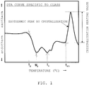
- the characteristic temperature was measured by the differential thermal analysis (DTA) .
- Fig. 1 shows an example of a typical DTA curve peculiar to glass.
- DTA of glass is measured by using glass particles having a particle diameter of about tens of ⁇ meters, and further using high purity aluminum ( ⁇ -Al 2 O 3 ) particles as standard samples, at a temperature rising rate of 5 °C/min in the atmosphere. As shown in Fig.
- the starting temperature of the first endothermic peak is a transition point T g
- its endothermic peak temperature is a yield point M g
- the second endothermic peak temperature is a softening point T s
- the starting temperature of exothermic peak by crystallization is a crystallization starting temperature T cry .
- the respective characteristic temperatures are obtained by tangential line method.
- the characteristic temperatures T g , M g , and T s are defined by glass viscosity.
- the temperature T g corresponds to 10 14.3 Pa ⁇ s (10 13.3 poise) Mg, to 10 12.0 Pa ⁇ s (10 11.0 poise) and T s ,10 8.65 Pa ⁇ s (10 7.65 poise).
- the crystallization tendency is determined from the crystallization starting temperature T cry , the size of the exothermic peak by crystallization, i.e., its heating value. It can be said that it is glass with suppressed crystallization by increase of the temperature T cry , i.e., increase of temperature difference between the temperature T s and the temperature T cry and reduction of the crystallization heating value.
- the firing temperature upon sealing or bonding of various parts and formation of electrode/wiring or conductive/heat dissipation junction by using the conventional low-melting glass composition is influenced by type, content and particle diameter of the contained ceramic particles or metal particles, and further, by firing conditions and the like such as temperature rising rate, atmosphere, and pressure.
- the firing temperature is set to be higher than the softening point T s by about 30 to 50 °C in many cases.
- the low-melting glass composition has good softening liquidity without crystallization.
- the characteristic temperatures such as the transition point T g , the yield point M g and the softening point T s are remarkably lower than conventional.
- the respective temperature differences are small, i.e., the viscosity gradients are large, it is possible to obtain good softening liquidity by holding even a firing temperature around the softening point T s . Further, even when the holding time is short, sufficient softening liquidity is obtained at a temperature higher than the softening point T s by barely about 20 °C.
- the softening point T s of the lead-free glass composition according to the present invention is low, i.e., it is equal to or lower than 200 °C.
- tin solder not containing lead or cadmium it is possible to perform firing at a use temperature equal to or lower than that of tin solder not containing lead or cadmium, more particularly, lower than the melting point of tin (231.9 °C), or preferably equal to or lower than 200 °C.
- the glass composite material contains the lead-free glass composition according to the present invention, and one or more of ceramic particles, metal particles, and resin.
- the glass composite material containing the ceramic particles contains a lead-free glass composition equal to or greater than 40 volume % and less than 100 volume %, and the ceramic particles greater than 0 volume % and less than 60 volume %.
- the lead-free glass composition is equal to or greater than 40 volume %, or that of the ceramic particles is equal to or less than 60 volume %, it is possible to obtain good softening liquidity.
- the ceramic particles may preferably be at least any of zirconium phosphate tungstate (Zr 2 (WO 4 )(PO 4 ) 2 ), quartz glass (SiO 2 ), zirconium silicate (ZrSiO 4 ), alumina (Al 2 O 3 ), mullite (3Al 2 O 3 ⁇ 2SiO 2 ), and niobium oxide (Nb 2 O 5 ).
- the ceramic particle effectively used for low-temperature expansion of the glass composite material is a compound mainly of zirconium phosphate tungstate (Zr 2 (WO 4 )(PO 4 ) 2 ) or zirconium phosphate tungstate (Zr 2 (WO 4 )(PO 4 ) 2 ), and a preferable content of which is 30 volume % to 50 volume %.
- the glass composite material containing the metal particles contains the lead-free glass composition equal to or greater than 5 volume % and less than 100 volume %, and the metal particles greater than 0 volume % and equal to or less than 95 volume %.
- the lead-free glass composition is equal to or greater than 5 volume % or the metal particles is equal to or less than 95 volume %, it is possible to improve firing among the metal particles and bonding property to the base material.
- the metal particles may preferably be at least any of gold (Au), silver (Ag), a silver alloy, copper (Cu), a copper alloy, aluminum (Al), an aluminum alloy, tin (Sn), and a tin alloy.
- the metal particle effectively used for improvement of conductivity and heat dissipation of the glass composite material is silver (Ag) or aluminum (Al), and a preferable content of which is equal to or greater than 10 volume % and less than 90 volume %.
- the lead-free glass composition according to an embodiment of the present invention promotes firing of silver (Ag) particles, and further, eliminates a surface oxide film of aluminum (Al) particles.
- the glass composite material containing resin contains the lead-free glass composition equal to or greater than 5 volume % and less than 100 volume %, and the resin greater than 0 volume % and equal to or less than 95 volume %.
- the lead-free glass composition is equal to or greater than 5 volume % or the resin is equal to or less than 95 volume %, it is possible to effectively compound the lead-free glass composition and the resin.
- the resin may preferably be at least any of epoxy resin, phenoxy resin, phenol resin, acrylic resin, urethane resin, and fluororesin. It is possible to obtain good softening liquidity in the resin of the lead-free glass composition by using these resins.
- the glass paste contains the glass composite material containing the lead-free glass composition and a solvent.
- a solvent it is preferable to use ⁇ -terpineol or butylcarbitol. These solvents are hardly crystallized in the lead-free glass composition. Further, it is possible to add a viscosity modifier, a wetting Agent or the like in accordance with necessity to adjust stability and coating property of the glass paste.
- the glass composite material or the glass paste When sealing and/or bonding is performed in the sealing structure using the glass composite material containing the ceramic particles and its glass paste, it is preferable to provide or apply the glass composite material or the glass paste in the sealing position of the sealed member or the bonding position of the bonded member, and fire the position within a temperature range from a neighboring temperature of the softening point T s of the contained lead-free glass composition to a temperature higher than the softening point T s by about 20 °C.
- the lead-free glass composition having a reduced crystallization tendency and a low-temperature softening point is used in the glass composite material or the glass paste, it is possible to improve the softening liquidity at a low temperature and lower the firing temperature.
- the lead-free glass composition according to another embodiment of the present invention has good chemical stability, it is possible to ensure the reliability of the sealing structure.
- the glass composite material containing the metal particles and its glass paste is used for formation of electrodes/wirings and conductive junctions in an electrical/electronic component, it is preferable to provide or apply the glass composite material or the glass paste in a predetermined position of the base material or the like, and fire the position within a temperature range from a neighboring temperature of the softening point T s of the contained lead-free glass composition to a temperature higher than the softening point T s by about 20 °C.
- the used metal particle is susceptible to oxidation, to prevent oxidation of the metal particle, it is desirable to prepare inert gas or vacuum environment as firing atmosphere.
- the lead-free glass composition having a reduced crystallization tendency and a low-temperature softening point is used in the glass composite material or the glass paste, it is possible to improve the softening liquidity at a low temperature and lower the firing temperature. As a result, it is possible to lower the forming temperature of the electrodes/wirings and conductivity/heat dissipation junction, i.e., the firing temperature. With this configuration, it is possible to reduce the influence on the environmental load, and to attain reduction of thermal damage to the electrical/electronic component (high functionality) and improvement of productivity (takt reduction). Further, the lead-free glass composition according to another embodiment of the present invention has good chemical stability, accordingly, it is possible to ensure the reliability of the electrical/electronic component.
- the glass composite material containing resin and its glass paste is used for formation of a coating film in a coated component
- metals, ceramics or glass is effective as the base material.
- the glass composite material or the glass paste is provided or applied in a predetermined position of the base material, and the position is fired within a temperature range from a neighboring temperature of the softening point T s of the contained lead-free glass composition to a temperature higher than the softening point T s by about 20 °C.
- the lead-free glass composition having a reduced crystallization tendency and a low-temperature softening point is used in the glass composite material or the glass paste, it is possible to improve the softening liquidity at a low temperature and lower the firing temperature. With this configuration, it is possible to reduce the influence on the environmental load, and further, to improve the reliability in the coated component such as coating film adhesive property, thermal resistance, chemical stability and the like.
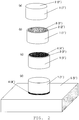
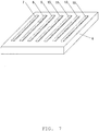
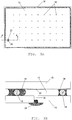
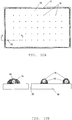
- the glass composite material or the glass paste according to another embodiment of the present invention is preferably used for sealing in a vacuum insulation multilayer glass panel used as window glass or the like, a display panel such as a plasma display panel, an organic EL display panel, a fluorescent display tube or the like, and a package device such as a crystal oscillator, an IC package, a MEMS and the like.
- the sealing structure using the glass composite material or the glass paste is formed with inner space and glass composite material, and has a sealing part to partition at least a part of the border between the inner space and the outside. It is preferable that the content of the lead-free glass composition contained in the glass composite material forming the sealing part is equal to or greater than 50 volume %. Further, it is effective that the glass composite material contains ceramic particles.
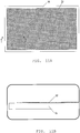
- the glass composite material or the glass paste according to another embodiment of the present invention is preferably used for formation of electrodes, wirings, a conductive junction and a heat dissipation junction in an electrical/electronic component such as a photovoltaic cell, an image display device, a multilayer capacitor, an inductor, a crystal oscillator, a resin wiring board, a light emitting diode (LED), a multilayer circuit board, or a semiconductor module.
- the electrical/electronic component formed with the glass composite material or the glass paste has electrodes, wirings, a conductive junction or a heat dissipation junction of the glass composite material. It is preferable that the content of the metal particles contained in the glass composite material forming the electrodes, the wirings, the conductive junction or the heat dissipation junction is equal to or greater than 50 volume %.
- the glass composite material and the glass paste according to another embodiment of the present invention may be used as a coating material.
- the coated component formed with the glass composite material or the glass paste has members, and the coating film formed on the members.
- the member is a base material of metal, ceramic or glass, and the coating film contains the glass composite material according to the present invention.
- the glass composite material forming the coating film contains resin, and the content of the resin is equal to or greater than 50 volume %.
- the coated component an electric cable, a vehicle body, an airframe, a washing machine tub, a toilet stool, a bathtub tile and the like are given. Examples
- a lead-free glass composition containing oxides of silver (Ag), tellurium (Te), and vanadium (V) as main components, and further containing one or more oxides of yttrium (Y), lanthanum (La), cerium (Ce), erbium (Er), ytterbium (Yb), aluminum (Al), gallium (Ga), indium (In), iron (Fe), tungsten (W), and molybdenum (Mo), as additional components, is manufactured.
- the influence of the glass composition on glass properties was examined. Note that as the glass properties, a vitrification state, characteristic temperatures, softening liquidity, and chemical stability of the manufactured lead-free glass composition were evaluated.
- Lead-free glass compositions A-01 to A-41 (examples) shown in Table 1 to be described later, and lead-free glass compositions B-01 to B-48 (comparative examples) shown in Table 2 were manufactured.
- the compositions shown in Table 1 and Table 2 are compound compositions upon manufacturing of glass.
- powders of V 2 O 5 by Shinko Chemical Co. , Ltd. TeO 2 by Kojundo Chemical Laboratory Co., Ltd., and Ag 2 O by FUJIFILM Wako Pure Chemical Corporation were used.
- powders of Y 2 O 3 , La 2 O 3 , CeO 2 , Er 2 O 3 , Yb 2 O 3 , Al 2 O 3 , Ga 2 O 3 , In 2 O 3 , Fe 2 O 3 , WO 3 , MoO 3 , BaCO 3 , and P 2 O 5 all by Kojundo Chemical Laboratory Co., Ltd. were used.
- the powder of the respective starting materials were subjected to weighing, compounding, and mixing such that the total amount was about 200 g, and the powders were fed to a quartz glass crucible.
- the quartz glass crucible in which the mixed material powders were fed was set in a glass melting furnace, and heated at a temperature rising rate of about 10 °C/min up to 700 to 750 °C.
- the quartz glass crucible was held for 1 hour while the composition was being stirred with an alumina bar. Thereafter, the quartz glass crucible was taken out from the glass melting furnace.
- the melt was poured into a stainless mold previously heated to about 100 °C, thus the lead-free glass compositions A-01 to A-41 as the examples and the lead-free glass compositions B-01 to B-48 as the comparative examples were respectively manufactured.
- the manufactured lead-free glass compositions were pulverized to a size under 45 ⁇ m.
- the vitrification state of the manufactured lead-free glass compositions A-01 to A-41 and B-01 to B-48 was evaluated by using the glass powder. The evaluation was made as to whether or not the crystals were precipitated by X-ray diffraction. When the precipitation of the crystals was not observed, it was determined that the vitrification state was good, and evaluated as "accepted”. On the other hand, when the precipitation of the crystals was observed, it was determined that the vitrification state was not uniform noncrystal state, and evaluated as "rejected".
- the characteristic temperatures of the manufactured lead-free glass compositions A-01 to A-41 and B-01 to B-48 were evaluated by using the glass powder, by differential thermal analysis (DTA) .
- DTA differential thermal analysis
- a macrocell type cell was used. About 500 mg glass powder was fed in the macrocell, and heated at a temperature rising rate of about 5 °C/min in the atmosphere from a room temperature up to 300 °C, and a DAT curve as shown in Fig. 1 was obtained.
- the transition point T g , the yield point M g and the softening point T s were measured from the obtained DAT curve. Note that upon evaluation of the characteristic temperatures, regarding the lead-free glass composition with the "rejected" vitrification state, the DTA was not performed.
- the softening liquidity of the manufactured lead-free glass compositions A-01 to A-41 and B-01 to B-48 was evaluated by using the glass powder, by a button flow test of the manufactured molded powder compact.
- the molded powder compact was molded by using a metal mold and a hand press, on the condition of 1 ton/cm 2 , to have a columnar shape with a diameter of about 10 mm and a height of about 5 mm.
- the molded powder compact set on an alumina ceramics substrate was introduced in an electric furnace. It was heated at a temperature rising rate of about 10 °C/min in the atmosphere from a room temperature up to, 180 °C, 190 °C, 200 °C, 210 °C, and 220 °C, respectively.
- the chemical stability of the manufactured lead-free glass compositions A-01 to A-41 and B-01 to B-48 was evaluated by a humidity resistance test and an acid resistance test.
- a humidity resistance test As a glass test piece, an about 10 to 20 mm cullet before pulverization was used.
- the humidity resistance test the cullet was left for 10 days on the conditions of 80 °C temperature and 90% humidity.
- the acid resistance test the cullet was immersed in a 1N hydrochloric acid aqueous solution at room temperature for 3 days. After the both tests, the outer appearance of the cullet was visually observed. When there was no change in the outer appearance, it was determined as "accepted” . On the other hand, when a change was found, it was determined as "rejected".
- Table 1 and Table 2 show the result of evaluation of the vitrification state, the characteristic temperatures, the softening liquidity, and the chemical stability of the lead-free glass compositions A-01 to A-41 according to the example and the lead-free glass compositions B-01 to B-48 as the comparative examples.
- the unit of the main component and subcomponent values is mol %.
- the vitrification state of the glass compositions B-01 to B-03 and B-06 as the comparative examples was "rejected” since the metal Ag and the like were precipitated.
- the vitrification state of other glass compositions (examples A-01 to A-41, and the comparative examples B-4, B-5 and B-7 to B-48) than the glass compositions B-01 to B-03 and B-06 was good and "accepted”.
- these lead-free glass compositions as the examples and the comparative examples have both "accepted” humidity resistance and acid resistance i.e. have excellent chemical stability.
- the softening point T s of the lead-free glass compositions B-4, B-5 and B-7 to B-48 was higher than 200 °C.
- the glass composition B-04 is an easily-crystallized glass composition. Accordingly, the softening liquidity of the glass compositions B-4, B-5 and B-7 to B-48 within a temperature range of 180 to 220 °C was not “fluidized” but “softened” at best. Further, none of these lead-free glass composition as comparative examples was "softened” at or lower than 200 °C.
- all the lead-free glass compositions A-01 to A-41 as the examples have low softening point T s equal to or lower than 200 °C, and good softening liquidity was obtained at or lower than 220 °C.
- the softening liquidity at 180 to 200 °C was "fluidized", however, at higher temperatures of 210 °C and 220 °C, surface devitrification due to crystallization which inhabits "fluidized” was observed. It is considered that this occurred since the content of La 2 O 3 as the additional component was small. In the other examples A-02 to A-41, this surface devitrification was not observed.
- an effective glass composition contains Ag 2 O, TeO 2 , and V 2 O 5 as main components, and further, contains at least one of Y 2 O 3 , La 2 O 3 , CeO 2 , Er 2 O 3 , Yb 2 O 3 , Al 2 O 3 , Ga 2 O 3 , In 2 O 3 , Fe 2 O 3 , WO 3 and MoO 3 by a small amount, as an additional component, and the contents of the main components are, represented by mol %, Ag 2 O > TeO 2 ⁇ V 2 O 5 and Ag 2 O ⁇ 2V 2 O 5 , and the content of TeO 2 is 25 mol % to 37 mol %.
- the content of Ag 2 O was equal to or greater than 40 mol % and less than 50 mol % and the content of V 2 O 5 was equal to or greater than 20 mol % and less than 30 mol %.
- the content of the above-described additional component was, when calculated in terms of the oxides as shown below, 0.1 mol % to 3.5 mol %.
- one or more of Y 2 O 3 , La 2 O 3 , and Al 2 O 3 are preferable, and it was effective that the content was, represented by mol %, Ag 2 O + Ln 2 O 3 ⁇ 2V 2 O 5 (Ln: Y, La, Al).
- an especially preferable content of additional component was, when calculated in terms of the oxides as described above, 0.3 mol % to 1.5 mol %.
- the softening point T s as the second endothermic peak temperature by the differential thermal analysis was equal to or lower than 200 °C.
- the same type metal base materials, glass base materials, and ceramic base materials were bonded, using the glass composite material containing the lead-free glass composition and the ceramic particles, and the bonded states, represented as shear stress, were evaluated.
- the lead-free glass composition the two types of compositions, A-05 and A-22 shown in Table 1, and as the ceramic particles, seven types of ceramic particles shown in Table 3 (CF-01 to CF-07) were used. Note that Table 3 also shows densities and thermal expansion coefficients of these ceramic particles. With respect to these values, the density of the lead-free glass composition shown in Table 1 was about 6g/cm 3 , and the thermal expansion coefficient was within a range of about 180 ⁇ 10 -7 to 200 ⁇ 10 -7 /°C.
- metal base materials aluminum (Al), silver (Ag), copper (Cu), nickel (Ni), and iron (Fe) were used, and as the glass base material, soda lime glass was used, and further, as the ceramic substrate, alumina (Al 2 O 3 ) was used.
- glass paste containing the lead-free glass composition particles, the ceramic particles, and a solvent was manufactured. The paste was applied to the respective base materials, and the base materials were subjected to drying and temporary firing. Then the base materials were attached to each other and heated, thus the base materials were bonded. [Table 3] No.
- the glass paste was manufactured by compounding and mixing the lead-free glass composition particles, the ceramic particles, and the solvent.
- the lead-free glass composition particles the glass compositions A-05 and A-22 having a particle diameter of about 10 ⁇ m were used, and as the ceramic particles, zirconium phosphate tungstate (CF-01) having a particle diameter of about 10 to 30 ⁇ m, zirconium phosphate tungstate microcontaining iron tungstate (CF-02), quartz glass (CF-03), zirconium silicate (CF-04), alumina (CF-05), mullite (CF-06), and niobium oxide (CF-07) were used.
- ⁇ -terpineol was used as the solvent, and isobonyl cyclohexanol was added as a viscosity modifier. Further, upon firing in the atmosphere, butylcarbitol acetate was used as the solvent, and ethylcellulose was used as a resin binder.
- the respective glass pastes were manufactured, at eight compounding ratios between the lead-free glass composition particles and the ceramic particles, represented by volume %, 100:0, 90:10, 80:20, 70:30, 60:40, 50:50, 40:60, and 30:70. Further, the content of solid in the glass paste (sum of the lead-free glass composition particles and the ceramic particles) was about 75 to 80 mass %.
- Fig. 2 shows a manufacturing method of the evaluation sample.
- a columnar base material 1 with a bonded surface 2, having a diameter of 5 mm and a thickness of 2 mm was prepared (a).
- glass paste 3 was applied to the bonded surface 2 of the columnar base material 1 by the dispenser method (b).
- the base material 1 was dried for 30 minutes at 150 °C in the atmosphere. Then, by setting the base material 1 in the electric furnace, heating it at a temperature rising rate of 10 °C/min in the inert gas (in nitrogen) or in the atmosphere up to 200 °C, and holding it for 15 minutes, the glass composite material 4 was formed on the bonded surface 2 of the columnar base material 1 (c).
- the bonded body was manufactured by setting the base material 1 on the same type of plate base material 5 having a thickness of 1 to 3 mm, holding it with a thermal resistant clip, heating it at a temperature rising rate of 10 °C/min in the inert gas (in nitrogen) or in the atmosphere up to 190 °C, and holding it for 30 minutes (d) .
- the shear stress was measured with this bonded body. Note that when copper (Cu) and iron (Fe) were used as the base materials, the heating atmosphere was the inert gas (in nitrogen), and in other cases, the heating was performed in the atmosphere. Further, in consideration of the thermal expansion coefficient of the base material, the compounding ratio between the lead-free glass composition particles and the ceramic particles in the glass paste and the type of the ceramic particles were selected. The thermal expansion coefficients of the used base materials were as follows.
- the expansion coefficient of aluminum (Al) was 224 ⁇ 10 -7 /°C; silver (Ag), 197 ⁇ 10 -7 /°C; copper (Cu), 164 ⁇ 10 -7 /°C; nickel (Ni), 133 ⁇ 10 -7 /°C; iron (Fe), 127 ⁇ 10 -7 /°C; soda lime glass, 88 ⁇ 10 -7 /°C; and alumina (Al 2 O 3 ), 81 ⁇ 10 -7 /°C.
- the shear stress was evaluated in the bonded bodies manufactured by using the respective types of glass pastes.
- the evaluation of shear stress was determined as "excellent” when it was equal to or higher than 30 MPa; "good” when it was 20 to 30 MPa; “normal” when it was 10 to 20 MPa; and “rejected” when it was lower than 10 Mpa.
- Tables 4 to 10 show the results of the evaluation of the shear stress of the bonded bodies in the respective base materials.
- Table 4 shows the evaluation results of the bonded body using the aluminum (Al) base materials; Table 5, the evaluation results of the bonded body using the silver (Ag) base materials; Table 6, the evaluation results of the bonded body using the copper (Cu) base materials; Table 7, the evaluation results of the bonded body using the nickel (Ni) base materials; Table 8, the evaluation results of the bonded body using the iron (Fe) base materials; Table 9, the evaluation results of the soda lime glass base materials; and Table 10, the evaluation results of the bonded body using the alumina (Al 2 O 3 ) base materials.
- the ceramic particles CF-04 to CF-05 in Table 3 were used as the ceramic particles, and the contents (compounded amounts) were 0 to 20 volume % (equal to or greater than 0 volume % and equal to or less than 20 volume %), and the contents of the lead-free glass compositions A-05 and A-22 were within a range of 80 to 100 volume %. Excellent results were obtained on all the conditions. It was found that bonding force and adhesive force to aluminum (Al) are very high in both of the A-05 and A-22 glass compositions.
- the ceramic particles CF-04, CF-05 and CF-06 in Table 3 were used as the ceramic particles, and the contents (compounded amounts) were 20 to 40 volume %, and the contents of the lead-free glass compositions A-05 and A-22 were within a range of 60 to 80 volume %. "Good” or higher results were obtained on all the conditions, and similar results were obtained in both of the glass compositions A-05 and A-22.
- the contents (compounded amounts) were increased in correspondence with combination with the ceramic particles CF-04 or CF-06, the bonding force and the adhesive force to copper (Cu) were improved since matching between the copper (Cu) and the thermal expansion coefficient was promoted.
- the ceramic particles CF-07 the results were opposite, since thermal expansion coefficient of the ceramic particles CF-07 is very low in comparison with that of the ceramic particles CF-04 and CF-06.
- the ceramic particles CF-03, CF-06 and CF-07 in Table 3 were used as the ceramic particles.
- the contents (compounded amounts) were 30 to 50 volume %, and the contents of the lead-free glass compositions A-05 and A-22 were within a range of 50 to 70 volume %. "Good” or higher results were obtained on all the conditions, and similar results were obtained in both of the glass compositions A-05 and A-22. It was found that in the ceramic particles CF-03, when the content (compounded amount) is 40 volume %, the shear stress is the highest, and the bonding force and the adhesive force to the nickel (Ni) base material are very high.
- the ceramic particles CF-01 to CF-03 in Table 3 were used as the ceramic particles, and the contents (compounded amounts) were 30 to 50 volume %, and the contents of the lead-free glass compositions A-05 and A-22 were within a range of 50 to 70 volume %. "Good” or higher results were obtained on all the conditions, and similar results were obtained in both of the glass compositions A-05 and A-22. It was found that in the ceramic particles CF-01 and CF-02, high shear stress is obtained regardless of content (compounded amount), and the bonding force and the adhesive force to iron (Fe) are very high.
- the thermal expansion coefficients of the ceramic particles CF-01 and CF-02 are the smallest in Table 3, and further, wettability and bonding with respect to the glass compositions A-05 and A-22 are good, the thermal expansion coefficient as the glass composite material is effectively and greatly reduced, and is easily matched to the thermal expansion coefficient with respect to the iron (Fe) substrate, which obtains the good and higher results.
- the results were not so high as these results, and it was found that the shear stress is increased in accordance with increment of the content (compounded amount), and the bonding force and the adhesive force to the iron (Fe) base material are improved. This result is also attained by matching between the thermal expansion coefficient and iron (Fe).
- the ceramic particles CF-01 and CF-02 in Table 3 were used as the low-thermal expansion ceramic particles, the contents (compounded amounts) were 40 to 70 volume %, and the contents of the lead-free glass compositions A-05 and A-22 were within a range of 30 to 60 volume %.
- the shear stress almost no difference was observed between the ceramic particles CF-01 and CF-02, and between the glass compositions A-05 and A-22.
- the content (compounded amount) of the lead-free glass composition according to the present invention is equal to or greater than 40 volume %, and the content (compounded amounts) of the ceramic particles is equal to or less than 60 volume %.
- the content (compounded amounts) of the ceramic particles is equal to or less than 60 volume %.
- the glass composite material containing 40 to 100 volume % lead-free glass composition and 0 to 60 volume % ceramic particles it is possible to realize low-temperature sealing and low-temperature adhesion of various base materials in air-tight manner.
- the glass compositions A-05 and A-22 have been described as representative lead-free glass, however, regarding the lead-free glass compositions A-01 to A-41, it is possible to exhibit equivalent performance.
- zirconium phosphate tungstate Zr 2 (WO 4 ) (PO 4 ) 2
- quartz glass SiO 2
- zirconium silicate ZrSiO 4
- alumina Al 2 O 3
- mullite 3Al 2 O 3 • 2SiO 2
- niobium oxide Nb 2 O 5
- the same type of and different types of metal base materials are bonded using the glass composite material containing the lead-free glass composition and the metal particles, and the bonded states were evaluated by using electric resistance (connection resistance) between the metal base materials.
- the lead-free glass composition the glass composition A-18 shown in Table 1 was used, and as the metal particles, three types of metal particles of silver (Ag), copper (Cu), aluminum (Al), and tin (Sn) were used.
- the metal base materials aluminum (Al), copper (Cu), nickel (Ni), and iron (Fe) were used.
- the glass paste containing the lead-free glass composition particles, the metal particles, and a solvent was manufactured. The paste was applied to the aluminum (Al) base material.
- the base material was dried, then temporarily fired, and attached to the same type or different type of metal base material, and bonded by resistance welding, as an evaluation sample.
- the glass paste was manufactured by compounding and mixing the lead-free glass composition particles, the metal particles, and the solvent.
- the lead-free glass composition particles the particles of glass composition A-18 having a particle diameter of about 3 ⁇ m were used, and as the metal particles, spherical silver (Ag) particles having an average particle diameter of about 2 ⁇ m, spherical copper (Cu) particles having an average particle diameter of about 15 ⁇ m, spherical aluminum (Al) particles having an average particle diameter of about 3 ⁇ m, and tin (Sn) particles having an average particle diameter of about 30 ⁇ m, were used.
- the respective glass pastes were manufactured, at seven types of compounding ratios between the lead-free glass composition particles and the metal particles, represented by volume %, 100:0, 80:20, 60:40, 40:60, 30:70, 20:80, and 10:90. Further, the content of solid in the glass paste (sum of the lead-free glass composition particles and the metal particles) was about 75 to 80 mass %.
- an evaluation sample and the manufacturing method similar to those in the example 2 were used. That is, in the present example, the evaluation sample and the manufacturing method were in accordance with those shown in Fig. 2 .
- glass paste 3' was applied to the bonded surface 2' of the columnar base material 1' by the dispenser method (b).
- the base material was dried at 150 °C in the atmosphere . Then by setting the base material in the electric furnace, heating it at a temperature rising rate of 10 °C/min in the atmosphere up to 200 °C, and holding it for 15 minutes, a glass composite material 4' was formed on the bonded surface 2' of the aluminum (Al) columnar base material 1' (c).
- the base material was set on a plate metal base material 5' of aluminum (Al), copper (Cu), nickel (Ni), and iron (Fe), having a thickness of about 1 mm.
- connection resistance between the metal base materials was measured.
- connection resistance electrical resistance between the metal base materials was measured by the four-terminal method. Further, as a comparison, bonding was performed using lead-free tin solder in inert gas (in argon) at 250 °C-10 min.
- the connection resistance by solder was, in the Al and Al solder bonded body, 3.2 ⁇ 10 -3 ⁇ /mm 2 ; in the Al and Cu solder bonded body, 1.5 ⁇ 10 -3 ⁇ /mm 2 ; in the Al and Ni solder bonded body, 1.7 ⁇ 10 -3 ⁇ /mm 2 ; and in the Al and Fe bonded body, 1.9 ⁇ 10 -3 ⁇ /mm 2 .
- connection resistance in the Cu and Cu solder bonded body was 5.0 ⁇ 10 -6 ⁇ /mm 2 , these connection resistances were about thrice higher. It is considered that a natural oxidation film having high electric resistance, formed on the surface of the Al base material, caused this high connection resistance.
- Fig. 3 shows the relationship between the connection resistance when Al and Al, Al and Cu, Al and Ni, and Al and Fe were bonded with the glass composite material containing the lead-free glass composition A-18 and the metal particles Ag, and the content ratio between the glass composition A-18 and the Ag particles in the glass composite material.
- connection resistance of 10 -6 ⁇ /mm 2 level was attained in a wide range regardless of compounding ratio between the content of the glass composition A-18 and the content of the Ag particles.
- the connection resistance was stable and lower when the content of the glass composition A-18 was 40 to 20 volume % and the content of the Ag particles was 60 to 80 volume % in the glass composite material.
- connection resistances had good values lower than those in the Al solder bonded bodies by about 3 digits and equal to or lower than those in the Cu and Cu solder bonded bodies. It is considered that the electric resistance in the boundary surface was lowered, since the glass composition A-18 in the glass composite material was softened and fluidized, and reacted with the Al base material, then the natural oxidation film formed on the surface of the Al base material was eliminated, an Al-V alloy such as Al 3 V was generated in the boundary surface, and V was excluded from the glass composition A-18 and the metal Ag precipitated. Further, with the force current of the resistance welding, the metal Ag precipitated on the boundary surface was precipitated and grew in the current application direction.
- connection resistance of 10 -6 ⁇ /mm 2 level was attained in the respective bonded bodies.
- the Ag particles were not contained, spark occurred between the electrodes of the resistance welder. As this shortens the life of the electrodes of the resistance welder, attention should be paid.
- the glass composition material contained the Ag particles, necking was performed among the Ag particles with the metal Ag precipitated from the glass composition A-18 and resistance was further lowered.
- an appropriate content of the glass composition A-18 is 40 to 20 volume %, and an appropriate content of the Ag particles is 60 to 80 volume %.
- Fig. 4 shows the relationship between the connection resistance when Al and Al, Al and Cu, Al and Ni, and Al and Fe were bonded with the glass composite material containing the lead-free glass composition A-18 and the metal particles cu, and the content ratio between the glass composition A-18 and Cu particles in the glass composite material.
- connection resistance of the second-half of 10 -6 ⁇ /mm 2 level to the first-half of 10 -5 ⁇ /mm 2 level was attained in a wide range regardless of compounding ratio between the content of the glass composition A-18 and the content of the Cu particles.
- connection resistance was lower when the content of the glass composition A-18 was 80 to 40 volume % and the content of the Cu particles was 20 to 60 volume % in the glass composite material.
- the connection resistance is high. It is considered that the surface oxidation of the Cu particles in the glass composite material was the cause of this high connection resistance.
- Fig. 5 shows the relationship between the connection resistance when Al and Al, Al and Cu, Al and Ni, and Al and Fe were bonded with the glass composite material containing the lead-free glass composition A-18 and the metal particles Al, and the content ratio between the glass composition A-18 and the Al particles in the glass composite material.
- connection resistance of 10 -6 ⁇ /mm 2 level was attained in a wide range regardless of compounding ratio between the content of the glass composition A-18 and the content of the Al particles.
- the connection resistance was lower when the content of the glass composition A-18 was 40 to 20 volume % and the content of the Al particles was 60 to 80 volume % in the glass composite material.
- Fig. 5 shows the relationship between the connection resistance when Al and Al, Al and Cu, Al and Ni, and Al and Fe were bonded with the glass composite material containing the lead-free glass composition A-18 and the metal particles Al, and the content ratio between the glass composition A-18 and the Al particles in the glass composite material.
- connection resistance was slightly high. It was considered that since the Al particles are very cheaper than the Ag particles, it is advantageous to use both of the Al particles and the Ag particles as the metal particles for reduction of the resistance and cost reduction in the glass composite material and its glass paste. Accordingly, Al and Cu bonded bodies were respectively manufactured by using the glass composite material, such that the content of the glass composition A-18 in the glass composite material was constantly 30 volume % and the compounding ratio between the Al particles and the Ag particles by volume % was 30:40, and 40:30, as in the case of the above-described manufacturing, and the connection resistances were evaluated. As a result, connection resistance equal to that not containing Al particles but containing 70 volume % Ag particles was obtained. It was clarified that it is effective to use both of the Al particles and the Ag particles.
- Fig. 6 shows the relationship between the connection resistance when Al and Al, Al and Cu, Al and Ni, and Al and Fe were bonded with the conductive material containing the lead-free glass compositionA-18 and the metal particles Sn, and the content ratio between the glass composition A-18 and the Sn particles in the glass composite material.
- connection resistance of the second-half of 10 -6 ⁇ /mm 2 level to the first-half of 10 -5 ⁇ /mm 2 level was attained in a wide range regardless of compounding ratio between the content of the glass composition A-18 and the content of the Sn particles.
- connection resistance was lower when the content of the glass composition A-18 was 80 to 40 volume % and the content of the Cu particles was 20 to 60 volume % in the glass composite material. This shows a similar tendency to that in Fig. 4 using the Cu particles .
- connection resistance is high. It is considered that the surface oxidation of the Sn particles in the glass composite material was the cause of this high connection resistance.
- the lead-free glass composition according to the present invention into glass composite material and its glass paste to form a conductive junction for conduction between metal base materials at a low temperature, by compounding the lead-free glass composition with metal particles.
- conductivity and heat dissipation have some degree of correlation, it goes without saying that it is possible to develop the lead-free glass composition to glass composite material and its glass paste to form not only the conductive junction but also glass composite material and its glass paste to form a heat dissipation junction.
- the glass composition A-18 has been described as representative lead-free glass, however, regarding the lead-free glass compositions A-1 to A-41, similar performance is exhibited.
- the glass composite material and its glass paste contains metal particles, Ag, Cu, Al, and Sn have been described; however, the metal particles are not limited to these materials, but similar performance is exhibited in alloys of these materials.
- the solder In formation of the conductive junction or the heat dissipation junction between the metal base materials, the solder is frequently used. In consideration of differentiation from the solder, Ag particles and Al particles are effective as the metal particles contained in the glass composite and the glass paste. Further, it is difficult with the solder to satisfactorily perform conductive bonding and heat dissipation bonding in the case of the metal base material in which a natural oxidation film is formed on the surface as in the case of Al. In the glass composite material and its glass paste according to the embodiment of the present invention, it is possible to perform conductive bonding and heat dissipation bonding even in the case of such metal base material or the like, with the operation of the contained lead-free glass composition.
- glass composite material and the glass paste containing the metal particles when conductivity is allowed in the junction and sealing part, as glass material and its glass paste as described in the example 2.
- matching as in the case of the example 2 is not performed between the bonded member or the sealed member and the thermal expansion coefficient, but stress mitigation is performed in accordance with size or amount of contained metal particles, and low-temperature bonding or low-temperature sealing is performed.
- the glass composite material containing the lead-free glass composition and the metal particles electrodes/wirings were formed on various types of substrates, and electric resistance (wiring resistance) of the electrodes/wirings and adhesive property to the various types of substrates was evaluated.
- the lead-free glass composition the glass composition A-20 shown in Table 1 was used, and as the metal particles, silver (Ag), was used.
- the substrates an alumina (Al 2 O 3 ) substrate, a borosilicate glass substrate, a silicon (Si) substrate, a ferrite substrate, and a polyimide substrate were used.
- the electrodes/wirings were formed by manufacturing the glass paste containing the lead-free glass composition particles, the metal particles, and the solvent, applying the glass paste to the various types of substrates, drying and temporarily firing the substrates. They were used as the evaluation samples.
- the glass paste was manufactured by compounding and mixing the lead-free glass composition particles, the metal particles, and the solvent.
- the lead-free glass composition particles particles of the glass composition A-20 having a particle diameter of about 1 ⁇ m were used, and as the metal particles, spherical silver (Ag) particles having an average particle diameter of about 1.5 ⁇ m, were used. Further, ⁇ -terpineol was used as the solvent, and isobonyl cyclohexanol was added as a viscosity modifier.
- Table 11 shows compounding ratios between the lead-free glass composition A-20 particles and the metal particles Ag. At the compounding ratios shown in Table 11, seven types of glass pastes were manufactured. Note that the content of solid in the glass paste (sum of the lead-free glass composition particles and the metal particles) was about 75 to 80 mass %.
- the respective electrodes/wirings were formed in a wiring pattern shown in Fig. 7 using the seven types of glass pastes DH-01 to DH-07 shown in Table 11.
- As the substrates 6 in Fig. 7 an alumina (Al 2 O 3 ) substrate, a borosilicate glass substrate, a silicon (Si) substrate, a ferrite substrate, and a polyimide substrate were used.
- Wirings 7 to 13 correspond to the glass pastes DH-01 to 07 in Table 11.
- a 2 mm ⁇ 40 mm pattern was respectively applied by the screen printing method on the respective substrates, and the substrates were dried at 150 °C in the atmosphere. The film thickness at that time was 30 to 40 ⁇ m. They were set in an electric furnace, and heated at a temperature rising rate of 10 °C/min in the atmosphere up to 200 °C, and held for 30 minutes, thus the respective wirings 7 to 13 were formed on the substrates 6.
- the wiring resistance values of the wirings 7 to 13 formed on the respective substrates at the compounding ratios for the seven types of glass pastes DH-01 to 07 shown in Table 11 were measured by the four-terminal methods.
- the adhesive properties of the wirings 7 to 13 to the respective substrates were evaluated by a peeling test.
- a peeling tape was attached to the wirings formed on the respective substrates. When the tape was tore off, the wiring not peeled off from the substrate and not broken was evaluated as "accepted” . On the other hand, the wiring peeled off and/or broken was evaluated as "rejected".
- Fig. 8 shows the relationship between the wiring resistance of the wirings, formed with the glass composite material containing lead-free glass composition A-20 and the metal particles Ag on the respective substrates, and the content ratio between the glass composition A-20 and Ag in the conductive material.
- the substrates five types of substrates, the A 2 O 3 substrate, the borosilicate glass substrate, the Si substrate, the ferrite substrate, and the polyimide substrate, were examined. Almost no difference of wiring resistance by substrate was observed. In accordance with increment of Ag content and decrement of glass composition A-20 content, the wiring resistance was decreased. When the Ag content was 70 to 95 volume % and the glass composition A-20 content was within a range of 30 to 5 volume %, wiring resistance of 10 -6 ⁇ cm level was attained.
- the minimum value of the wiring resistance was obtained.
- the glass composite material according to Fig. 8 it is possible to promote necking of the Ag particles by obtaining good softening liquidity upon formation of the wirings. Accordingly, it is possible to form the electrodes/wirings with remarkably low wiring resistance at this low temperature, i.e. in the present example, at a low temperature of 200 °C.
- the five types of substrates the A 2 O 3 substrate, the borosilicate glass substrate, the Si substrate, the ferrite substrate, and the polyimide substrate were examined; however, it is easily guessed that the invention is applicable to other substrates than these substrates. Especially, development to resin substrates is greatly expected.
- Table 12 shows the results of the peeling test performed on the respective wirings formed on the respective substrates.
- the evaluation was "accepted", and good adhesive property was obtained with respect to any of the substrates .
- the glass composition A-20 content was 5 volume % and the Ag content was 95 volume %, the wiring was peeled off and the evaluation was "rejected", with respect to any of the substrates. The adhesive property was not sufficient. It is considered that this evaluation was resulted from the small content of the lead-free glass composition in the glass composite material.
- the preferable content of the lead-free glass composition is equal to or greater than 10 volume %.
- the content of the lead-free glass composition is 5 volume %, there is a good possibility of acquisition of good adhesive property if pressurization or the like is performed upon wiring formation.
- the glass composition A-20 has been described as representative lead-free glass, however, it goes without saying that regarding the lead-free glass compositions A-1 to A-41, similar performance is exhibited.
- Ag has been described as the metal particles contained in the glass composite material and its glass paste, however, the metal particles are not limited to this metal. It goes without saying that there is a possibility that the invention is applicable to an Ag alloy, Cu, Al, and Sn, or alloys of these metals. It was found that it is possible to effectively develop the glass composite material according to the embodiment of the present invention and its glass paste into formation of electrodes/wirings in various types of electronic components at a low temperature.
- the glass composite material containing the lead-free glass composition and resin adhesion strengths of metals, ceramic, and glass to the base material were evaluated.
- the lead-free glass composition the glass composition A-07 shown in Table 1 was used, and as the resin, six types of resins, epoxy resin, phenoxy resin, phenol resin, acrylic resin, urethane resin, and fluororesin, were used.
- the metal base materials aluminum (Al), copper (Cu), and iron (Fe) were used
- the ceramic base materials alumina (Al 2 O 3 ) and magnesia (MgO) were used, and as the glass base materials, soda lime glass and borosilicate glass, were used.
- the evaluation samples were formed by applying the glass paste, containing the lead-free glass composition particles, the resin, and the solvent, as a coating material, to the various types of base materials, and firing the base materials, to form coating films.
- the glass paste was manufactured by compounding and mixing the lead-free glass composition particles, the resin, and the solvent.
- the lead-free glass composition particles particles of the glass composition A-07 having a particle diameter of about 1 ⁇ m were used, and as the solvent, butylcarbitol acetate were used.
- the epoxy resin, the phenoxy resin, the phenol resin, the acrylic resin, the urethane resin, and the fluororesin were respectively dissolved in the solvent.
- the lead-free glass composition particles were introduced into the solutions, and the solutions were stirred well, thus the glass pastes were manufactured.
- the compounding ratios between the lead-free glass composition and the resins were, by volume %, 0:100 and 10:90.
- the content of solid in the glass paste (sum of the lead-free glass composition particles and the resin) was 75 to 80 mass %.
- the manufactured glass pastes were applied to the Al, Cu, and Fe metal base materials, the Al 2 O 3 and MgO ceramic base materials, and the glass base materials of the soda lime glass and borosilicate glass, respectively.
- the coating films were formed on the respective base materials by heating the base materials at a temperature rising rate of 10 °C/min in the atmosphere up to 150°C, then holding them for 15 minutes, thereafter, heating them at a temperature rising rate of 5 °C/min up to 190 °C, then holding them for 10 minutes.
- the adhesion strengths of the coating films formed on the respective base materials were evaluated by a scratch test (peeling strength).
- peel strength the adhesion strength of the coating film in which the compounding ratio between the lead-free glass composition and the resin was 0:100, i.e. the adhesion of a coating film not containing lead-free glass composition as "1”
- the adhesion strengths of the coating films containing the lead-free glass composition were relatively compared. That is, when the strength was above "1", the adhesion strength was improved. On the other hand, when the strength was below "1", the adhesion strength was reduced.
- Table 13 shows the results of the evaluation of relative adhesion strengths to the respective base materials when the content of the lead-free glass composition A-07 was 10 volume %.
- the adhesion strength was improved to twice or higher. It is considered that upon formation of coating film, the glass composition A-07 was softened and fluidized, and strongly bonded to the respective base materials, which caused the improvement of the adhesion strength.
- the adhesion strength was further improved.
- the adhesion strength differs in accordance with contained resin, especially, the adhesion strength was increased when the phenoxy resin and the phenol resin were contained. It is guessed that the softening liquidity of the glass composition A-07 was different in accordance with resin, and in the phenoxy resin and the phenol resin, the glass composition had good softening liquidity.
- the lead-free glass composition according to the embodiment of the present invention and the resin are compounded, it is possible to improve the adhesion strengths of the coating film to the metal, ceramic, and glass base materials.
- the glass composition A-07 has been described as a representative lead-free glass composition, however, regarding the lead-free glass compositions A-01 to A-41, equivalent performance is exhibited.
- general resin i.e. the epoxy resin, the phenoxy resin, the phenol resin, the acrylic resin, the urethane resin and the fluororesin were examined, however, the resin was not limited to these resins.
- the metal base materials to form the coating film the Al, Cu, and Fe metal base materials were used, as the ceramic base material, Al 2 O 3 and MgO were used, and as the glass base materials, soda lime glass and borosilicate glass were used, however, the base materials were not limited to these base materials.
- the influence of the compounding ratio between the lead-free glass composition and the resin on the adhesion strengths to the metal, ceramic and glass base materials was evaluated.
- the lead-free glass composition the glass composition A-07 shown in Table 1 was used, and as the resin, phenolic resin was used.
- the metal base materials aluminum (Al), copper (Cu), and iron (Fe) were used, as the ceramic base materials, alumina (Al 2 O 3 ) and magnesia (MgO) were used, and as the glass base materials, soda lime glass and borosilicate glass were used.
- the glass pastes containing the lead-free glass composition particles, the resin, and the solvent, as coating materials, were applied to the various types of base materials, and the base materials were fired, thus the coating films were formed, as evaluation samples.
- the glass paste was manufactured by compounding and mixing the lead-free glass composition particles, the resin, and the solvent.
- the lead-free glass composition particles particles of the glass composition A-07 having a particle diameter of about 1 ⁇ m were used, and as the solvent, butylcarbitol acetate was used.
- the lead-free glass composition particles were introduced into the butylcarbitol acetate in which the phenol resin was dissolved, and the solutions were well stirred, thus the glass pastes were manufactured.
- the compounding ratios between the lead-free glass composition and the resin were, by volume %, five types of ratios, 5:95, 10:90, 30:70, 50:50, and 70:30. Further, the content of solid in the glass paste (sum of the lead-free glass composition and the resin) was about 75 to 80 mass %.
- the coating films were formed on the respective base materials by applying the manufactured glass pastes to the Al, Cu, and Fe metal base materials, the Al 2 O 3 and MgO ceramic base materials, and the base materials of soda lime glass and borosilicate glass, heating the base materials at a temperature rising rate of 10 °C/min in the atmosphere up to 150 °C, holding the base materials for 15 minutes, then heating the base materials at a temperature rising rate of 5 °C/min up to 190 °C, and holding the base materials for 10 minutes.
- the adhesion strengths of the coating films formed on the respective base materials were evaluated by the scratch test (peeling strength).
- peel test peel strength
- the adhesion strength of a coating film not containing the lead-free glass composition was relatively compared. That is, when it was above "1", the adhesion strength was improved. On the other hand, when it was below “1", the adhesion strength was reduced.
- Table 14 shows the results of evaluation of the adhesion strengths relative to the respective base materials when the phenol resin was used.
- any of the base materials of Al, Cu, Fe, Al 2 O 3 , MgO, soda lime glass, and borosilicate glass a tendency that the adhesion strength of the coating film was increased in accordance with increment of the content of the lead-free glass composition A-07 then reduced was observed. Further, the maximum adhesion strength was not based on the type of base material. It was within a range that the content of the glass composition A-07 was 5 to 30 volume % and the content of the phenol resin was 70 to 95 volume %.
- the evaluation was above "1" , and the improvement of the adhesion strength was observed.
- the evaluation was below "1" when the content of the glass composition A-07 was above 50 volume % and the content of the phenol resin was less than 50 volume %, in most base materials, the evaluation was below "1", and the adhesion strength of the coating film was degraded.
- the adhesion strengths of the coating films to the metal, ceramic, and glass base materials are improved, and it is possible to effectively develop into the coating material to the metal, ceramic, and glass base materials.
- the coating film has an excellent adhesion strength, and it is very effective as a coating material to metal, ceramic and glass base materials.
- the lead-free glass composition according to the present invention it was found that in the lead-free glass composition according to the present invention, it is possible to realize, in addition to compounding with the ceramic particles and the metal particles described in the above examples 2 to 4, compounding with resin with lower thermal resistance than that of the above particles, and new development to coating materials and the like was found. Especially, upon development into the coating materials, when the base materials forming the coating films are metal, ceramic, and glass, the coating film can be strongly bonded. Accordingly, the invention is applicable to various coated components.
- a vacuum insulation multilayer glass panel was manufactured as one of representative examples of glass sealing parts, to substantiate applicability of the glass composite material.
- the glass paste was used as the glass composite material.
- Fig. 9A is a schematic plane diagram of the manufactured vacuum insulation multilayer glass panel. Further, Fig. 9B is an enlarged view of an A-A cross-section around a sealing part.
- the vacuum insulation multilayer glass panel has a sealing part 14 at peripheral edges of a soda lime glass substrate 15 and a soda lime glass substrate (numeral 16 in Fig. 9B ) stacked on the soda lime glass substrate 15 with a gap between them.
- Plural spacers 18 are two-dimensionally arrayed at equal intervals between these substrates (15, 16).
- An exhaust hole 20 is formed in the soda lime glass substrate (16). Exhaustion in the gap between the two substrates (15, 16) is performed by using a vacuum pump (not shown) from the exhaust hole 20.
- a cap 21 is attached to the exhaust hole 20.
- space 17 (the above-described gap) exists between the pair of soda lime glass substrates 15 and 16 having the sealing part 14 at the peripheral part (peripheral edges), and the space 17 is in vacuum state.
- the glass composite material according to the embodiment of the present invention is used. It is possible to develop the vacuum insulation multilayer glass panel into building material window glass, vehicle window glass, business-use refrigerators and refrigerator doors, and the like.
- the glass composite material used in the sealing part 14 contains, in addition to the lead-free glass composition according to the present invention, ceramic particles having a small thermal expansion coefficient for matching with respect to the thermal expansion coefficient of the soda lime glass substrates 15 and 16.
- the thermal resistance of the soda lime glass substrates 15 and 16 is about 500 °C, accordingly, it is necessary to form the sealing part 14 at a temperature equal to or lower than that temperature. Further, since the soda lime glass substrates 15 and 16 are easily damaged due to rapid heating or rapid cooling, it is necessary to gradually perform heating and cooling upon sealing. To improve the productivity of the vacuum insulation multilayer glass panel, sealing at temperature as low as possible is required. Further, the soda lime glass substrates 15 and 16 are frequently subjected to cooling and tempering for crime prevention and safety. The cooling and tempering is performed to form a compression reinforced layer on the surfaces of the soda lime glass substrates 15 and 16. The reinforced layer is gradually reduced by heating at a temperature equal to or higher than 300 °C, and disappears by heating at a temperature equal to or higher than 400 °C. From this fact, sealing at a lower temperature is strongly required.
- the plural spacers 18 are provided in the space 17 between the soda lime glass substrates 15 and 16. Further, to obtain the space 17 having an appropriate thickness, it is effective to introduce spherical beads 19 or the like having a uniformed particle diameter in the spacers 18 and the sealing part 14. Further, to fix the spacers 18, it is possible to utilize the glass composite material according to the embodiment of the present invention as in the case of the sealing part 14.
- the exhaust hole 20 is previously formed in the soda lime glass substrate 16, and exhaustion of the space 17 is performed by using the vacuum pump from the exhaust hole 20. After the exhaustion, the cap 21 is attached so as to maintain the vacuum degree in the space 17.
- the panel When the panel is applied to building material window glass, vehicle window glass or the like, it may be configured such that a heat-ray reflective film 22 is previously formed by the vapor deposition method or the like on the inner surface of the soda lime glass substrate 15.
- the soda lime glass substrates 15 and 16 having a size of 900 ⁇ 600 ⁇ 3 mm were used. Note that as the heat-ray reflective film 22 was formed on the soda lime glass substrate 15, and the exhaust hole 20 was formed in the soda lime glass substrate 16. To obtain the gap between the soda lime glass substrates 15 and 16, i.e. , the space 17 having a thickness of about 200 ⁇ m, the sealing part 14 and the spacers 18 contain the spherical beads 19 having a diameter slightly smaller than 200 ⁇ m. As the spherical beads 19, the soda lime glass was used. As the sealing part 14, the glass composite material of the lead-free glass composition A-08 shown in Table 1 and the ceramic particles CF-01 shown in Table 3 was used.
- the compounding ratio between the glass composition A-08 and the ceramic particles CF-01 was, by volume %, 65:35. Further, the sealing part 14 contained the spherical beads 19 by 1 volume % with respect to the glass composite material, and the spacers 18 contained the spherical beads by 20 volume % with respect to the glass composite material.
- the glass paste was manufactured by compounding and mixing the lead-free glass composition particles according to the embodiment of the present invention, the ceramic particles, and the solvent.
- the lead-free glass composition particles the glass composition A-08 having a particle diameter of about 15 ⁇ m was used, and as the ceramic particles, the ceramic particles CF-01 (zirconium phosphate tungstate) having a particle diameter of about 30 ⁇ m was used.
- the solvent ⁇ -terpineol was used, and isobonyl cyclohexanol was added as a viscosity modifier.
- the glass paste was manufactured such that the compounding ratio between the lead-free glass composition A-08 particles and the ceramic particles CF-01 was, by volume %, 65:35, and the content of solid (sum of the glass composition A-08 and the ceramic particles CF-01) was about 75 to 80 mass %. Further, the glass paste contained spherical beads of soda lime glass having a particle diameter of about 180 to 200 ⁇ m. The content of the beads with respect to the solid was 1 volume % for low-temperature sealing, and 20 volume % for the spacer.
- FIG. 10A A manufacturing method of the vacuum insulation multilayer glass panel according to the present example will be described by using Figs. 10A to 12 .
- Fig. 10A shows the soda lime glass substrate 16, forming the vacuum insulation multilayer glass panel shown in Figs. 9A and 9B , in which the sealing part 14 and the spacers 18 were formed.
- the above-described manufactured glass paste was applied to an outer peripheral part (sealing part 14) and the inside (spacers 18) of the soda lime glass substrate 16 respectively by the dispenser method, and the glass substrate was dried at 150 °C in the atmosphere.
- the substrate was heated at a temperature rising rate of 5 °C/min in the atmosphere up to 200 °C, then held for 30 minutes, such that the sealing part 14 and the spacers 18 were bonded to the soda lime glass substrate 16.
- Fig. 10B which is an A-A cross-sectional diagram shown in Fig. 10A
- the sealing part 14 and the spacers 18 contain the spherical beads 19.
- Fig. 11A shows the soda lime glass substrate 15 forming the vacuum insulation multilayer glass panel shown in Fig. 9B .
- Fig. 11B is an A-A cross-sectional diagram of Fig. 11A .
- the heat-ray reflective film 22 is formed on one surface of the soda lime glass substrate 15.
- Fig. 12 shows the last process of the manufacturing method of the vacuum insulation multilayer glass panel shown in Figs. 9A and 9B .
- the soda lime glass substrates 15 and 16 are faced each other, positioned with each other, and fixed with plural thermal resistance clips. The substrates were sealed by thermal processing while being vacuum exhausted.
- Fig. 13 shows a sealing temperature profile in the thermal processing.
- the sealing was performed by heating at a temperature rising rate of 5 °C/min in the atmosphere up to around the yield point M g of the employed lead-free glass composition, i.e. 153 °C as the yield point M g of the glass composition A-08 here, and holding for 30 minutes, then heating at a temperature rising rate of 5 °C/min up to around the softening point T s of the employed lead-free glass composition, i.e., 182 °C as the softening point T s of the glass composition A-08 here, while exhausting the inside of the panel with the vacuum pump from the exhaust hole 20, then holding for 30 minutes.
- the sealing part 14 and the spacers 18 were crushed, and bonded to the two soda lime glass substrates 15 and 16. Thereafter, the cap 21 was attached to the exhaust hole 20, thus the vacuum insulation multilayer glass panel was manufactured. Note that in the present example, ten vacuum insulation multilayer glass panels were manufactured.
- the glass composite material according to the embodiment of the present invention and by using the glass composite material, it is possible to remarkably lower the sealing temperature, which greatly contributes to improvement of productivity of the vacuum insulation multilayer glass panel and application of the soda lime glass substrate subjected to cooling and tempering.
- the application to the vacuum insulation multilayer glass panel using the glass composite material containing the lead-free glass composition according to the present invention and its glass paste has been described. It was confirmed that it is possible to effectively apply the glass composite material containing the lead-free glass composition according to the present invention and its glass paste to a sealing part of a sealing structure, and to provide a sealing structure having both excellent reliability and productivity. It goes without saying that it is also possible to effectively develop them into other sealing structures than the vacuum insulation multilayer glass panel.
- a display including a large number of organic light emitting diodes (OLED) between two borosilicate glass substrates was manufactured, to substantiate applicability of the glass composite material according to the present invention.
- OLED organic light emitting diodes
- Fig. 14A is a schematic plane diagram showing an example of the OLED display.
- Fig. 14B is an A-A cross-sectional diagram of Fig. 14A .
- the OLED display has the sealing part 14 as the glass composite material according to the embodiment of the present invention, at an outer peripheral part of a borosilicate glass substrate 23 and a borosilicate glass substrate (numeral 24 in Fig. 14B ) stacked on the above substrate with a gap between them.
- OLEDs 25 are incorporated between the borosilicate glass substrates (23 and 24).
- the glass composite material used in the sealing part 14 contains, in addition to the lead-free glass composition according to the present invention, ceramic particles having a small thermal expansion coefficient for matching with respect to the thermal expansion coefficient of the borosilicate glass substrates 23 and 24 as much as possible.
- the glass composite material of the lead-free glass composition A-19 shown in Table 1 and the ceramic particles CF-02 shown in Table 3 was used as the sealing part 14.
- the contents of the glass compositions A-19 and the ceramic particles CF-02 were 60:40 volume %. Further, in the present example, as the glass composite material, its glass paste was used, and as the solvent, high-viscosity ⁇ -terpineol was used.
- the glass paste was manufactured by compounding and mixing the lead-free glass composition particles, the ceramic particles, and the solvent.
- the lead-free glass composition particles the glass composition A-19 having an average particle diameter of about 1 ⁇ m
- the ceramic particles the ceramic particles CF-02 (a chemical compound mainly containing zirconium phosphate tungstate) having an average particle diameter of about 3 ⁇ m was used.
- the solvent ⁇ -terpineol was used, and isobonyl cyclohexanol was added as a viscosity modifier.
- iron tungstate FeWO 4
- the low-temperature sealing glass paste was manufactured such that compounding ratio between the lead-free glass composition A-19 particles and the ceramic particles CF-02 was, by volume %, 60:40, and the content of the solid (sum of A-19 and CF-02) was about 80 mass %.
- Figs. 15A to 17 show a manufacturing method of the OLED display according to the present example.
- Fig. 15A shows one substrate of the OLED display.
- Fig. 15B is an A-A cross-sectional diagram of Fig. 15A .
- the manufactured above-described glass paste was applied to an outer peripheral part of the borosilicate glass substrate 23 by the screen printing method, and the substrate was dried at 150 °C in the atmosphere.
- the substrate was heated at a temperature rising rate of 5 °C/min in the atmosphere up to 200 °C, and held for 30 minutes.
- the sealing part 14 was formed at the outer peripheral part of the borosilicate glass substrate 23.
- the sealing part 14 formed at the outer peripheral part of the borosilicate glass substrate 23 had a line width of about 2 mm, and a fired film thickness of about 15 ⁇ m.
- Fig. 16A shows the other substrate of the OLED display.
- Fig. 16B is an A-A cross-sectional diagram of Fig. 16A .
- the large number of OLEDs 25 corresponding to the number of pixels were formed on the borosilicate glass substrate 24.
- the borosilicate glass substrate 24 on which the OLEDs 25 were formed and the borosilicate glass substrate 23 on which the sealing part 14 was formed were faced each other as shown in Fig. 17 , and laser 26 was irradiated from the direction of the borosilicate glass substrate 23 toward the sealing part 14 in low-vacuum state.
- red semiconductor laser having a wavelength of 805 nm was used for effective absorption of the laser wavelength in the lead-free glass composition and the low-thermal expansion ceramic particles in the glass composite material, to cause heat generation, and promote softening and fluidization of the lead-free glass composition.
- the laser 26 was moved at the outer peripheral part at a speed of 10 mm/sec, and the outer peripheral parts of the borosilicate glass substrates 23 and 24 were bonded with the sealing part 14, thus the OLED display was manufactured.
- the OLED display was subjected to a high-temperature high-humidity test (saturated pressure cooker test) for 1 day, 3 days, and 7 days on the condition of 120 °C -100 % Rh -202 kPa, and the lighting test was similarly performed.
- the OLED display sealed only with resin was subjected to the test. Note that the line width of the resin sealing was about 5 mm, and the thickness was about 15 ⁇ m.
- the sealing structure As described above, in the present example, as one of representative examples of the sealing structure, the application to the organic light emitting diode (OLED) display using the glass composite material containing the lead-free glass composition according to the present invention and its glass paste has been described. It was confirmed that it is possible to effectively apply the glass composite material containing the lead-free glass composition according to the present invention and its glass paste to the sealing part of the sealing structure, and to provide a sealing structure in which both of high functionality including reliability and productivity are excellent. Further, from the result of the present example, it goes without saying that it is possible to effectively develop them to sealing structures which are thermal-damage susceptible such as OLED-mounted lighting equipment, an organic photovoltaic cell, an organic device-mounted MEMS sensor and the like.
- thermal-damage susceptible such as OLED-mounted lighting equipment, an organic photovoltaic cell, an organic device-mounted MEMS sensor and the like.
- a photovoltaic cell using a silicon (Si) substrate having a pn junction was manufactured, and it was examined and evaluated as to whether or not the glass composite material according to the present invention is applicable to the electrodes/wirings of the photovoltaic cell. Note that in the present example, as the glass composite material, its glass paste was used.
- Fig. 18A is a schematic diagram of a light receiving surface of the manufactured photovoltaic cell.
- Fig. 18B is a schematic diagram of the rear surface.
- Fig. 18C is an A-A cross-sectional diagram of Fig. 18A .
- Fig. 18A light receiving surface electrodes/wirings 28 and an antireflective film 31 are formed on the light receiving surface of the Si substrate 27 (silicon substrate) of the photovoltaic cell.
- collector electrodes/wirings 29 and output electrodes/wirings 30 are formed on the rear surface of the photovoltaic cell.
- the photovoltaic cell has a pn junction 31 on the light receiving surface side of the Si substrate 27.
- the glass composite material according to the embodiment of the present invention is used.
- lead-containing glass paste containing silver (Ag) particles and lead-containing low-melting glass composition particles was used, and for formation of the collector electrodes/wirings 29, lead-containing glass paste containing aluminum (Al) particles and lead-containing low-melting glass composition particles was used.
- the Si substrate 27 having the pn junction a monocrystal Si substrate for 150 ⁇ 150 ⁇ 0.2 mm photovoltaic cell was used. Further, as the light receiving surface of the Si substrate 27, the antireflective film 31 of silicon nitride (SiN) was formed by about 100 nm. As the light receiving surface electrodes/wirings 28 and the output electrodes/wirings 30, the glass composite material containing the lead-free glass composition A-35 shown in Table 1 and the spherical silver (Ag) particles having an average particle diameter of about 1.5 ⁇ m was used. The contents of the glass composition A-35 and the Ag particles were, by volume %, 20:80.
- a conductive material containing the lead-free glass composition A-38 shown in Table 1 and the spherical aluminum (Al) particles having an average particle diameter of about 3 ⁇ m was used as the collector electrodes/wirings 29 .
- the contents of the glass composition A-38 and the Al particles were 15:85 volume %.
- the glass paste was manufactured by compounding and mixing the lead-free glass composition A-35 or A-38 particles, the silver (Ag) or aluminum (Al) metal particles, and the solvent.
- the glass paste used in the light receiving surface electrodes/wirings 28 and the output electrodes/wirings 30 the glass composition A-35 particles having an average particle diameter of about 1 ⁇ m and the spherical Ag particles having the average particle diameter of about 1.5 ⁇ m were used, and the compounding ratio was, by volume %, 20:80.
- As the solvent ⁇ -terpineol was used, and isobonyl cyclohexanol was added as a viscosity modifier.
- the glass paste used in the collector electrodes/wirings 29 the glass composition A-38 particles having an average particle diameter of about 1 ⁇ m and the spherical Al particles having the average particle diameter of about 3 ⁇ m were used, and the compounding ratio was, by volume %, 15:85.
- the solvent ⁇ -terpineol was used, and isobonyl cyclohexanol was added as a viscosity modifier.
- the content of the solid (sum of the lead-free glass composition particles and the metal particles) in the paste was about 80 mass %.
- the glass paste manufactured as described above containing the glass composition A-35 particles and the Ag particles was applied to the light receiving surface side of the Si substrate 27 (150 ⁇ 150 ⁇ 0.2 mm), in which the antireflective film 31 was formed on the light receiving surface, by the screen printing method, and dried at about 150 °C.
- the substrate was heated at a temperature rising rate of about 20 °C/min up to 200 °C in a tunnel furnace, and was held for 30 minutes, thus the light receiving surface electrodes/wirings 28 were formed on the light receiving surface of the Si substrate 27.
- the glass paste containing the glass composition A-35 particles and the Ag particles the same as above was applied to the rear surface of the Si substrate 27, by the screen printing method, and dried at about 150 °C.
- the glass paste manufactured as described above containing the glass composition A-38 particles and the Al particles was applied by the screen printing method, and dried at about 150 °C.
- the substrate was fired on the same heating condition as that of the light receiving surface electrodes/wirings 28, thus the collector electrodes/wirings 29 and the output electrodes/wirings 30 were formed on the rear surface of the Si substrate 27.
- the twice heating history was added to the light receiving surface electrodes/wirings 28, with which electrical connection from the light receiving surface electrodes/wirings 28 to the Si substrate 27 became good. In this manner, the light receiving surface electrodes/wirings 28, the collector electrodes/wirings 29, and the output electrodes/wirings 30 were formed, thus the photovoltaic cell according to the present example was manufactured. Note that in the present example, ten photovoltaic cells were manufactured.
- this high-reliability photovoltaic cell is obtained by the characteristic reaction between the lead-free glass composition according to the present invention and Ag or Al.
- the present example as one of representative examples of the electrical/electronic component, an application to the photovoltaic cell having the electrodes/wirings formed by using the glass composite material containing the lead-free glass composition according to the example of the present invention and its glass paste has been described.
- the glass composite material containing the lead-free glass composition according to the present invention and its glass paste are not limited to the photovoltaic cell, but are effectively applicable to electrodes/wirings of various electrical/electronic components. It is possible to provide an electrical/electronic component in which high functionality including reliability, productivity, and yield improvement are excellent.
- a crystal oscillator package was manufactured, to examine whether or not the glass composite material according to the present invention is applicable to a conductive junction and a sealing part of the package. Note that in the present example, as the glass composite material, its glass paste was used.
- Figs. 19A to 19F show a manufacturing method of the crystal oscillator package.
- Fig. 19G is a cross-sectional schematic diagram of the manufactured crystal oscillator package.
- the crystal oscillator package shown in Fig. 19G has a crystal oscillator 32 provided via a conductive junction 35 on the surface of a ceramic substrate 33 having wirings 34.
- the wirings 34 and the conductive junction 35 are electrically connected.
- the crystal oscillator 32 is electrically connected to the outside.
- a ceramic cap 36 is used for protection of the crystal oscillator 32.
- the ceramic cap is airtightly bonded with a sealing part 37 to an outer peripheral part of the ceramic substrate 33.
- the conductive junction 35 the glass composite material containing the lead-free glass composition according to the present invention and the metal particles is used
- the sealing part 37 the glass composite material containing the lead-free glass composition according to the present invention and the ceramic particles is used.
- the manufacturing method of the crystal oscillator package is as follows.
- the ceramic substrate 33 on which the wirings 34 shown in Fig. 19A are formed is manufactured.
- the glass paste containing the metal particles is applied on the wirings 34, then dried, and heated in the atmosphere, such that the lead-free glass composition in the glass composite material is softened and fluidized, thus the conductive junction 35 is formed.
- the crystal oscillator 32 is provided on the conductive junction 35, and heated in inert gas or in vacuum environment, to again soften and fluidize the lead-free glass composition in the conductive junction 35 and establish electrical connection.
- the ceramic cap 36 shown in Fig. 19D is prepared. Then as shown in Fig. 19E , the glass paste containing the ceramic particles is applied to the outer peripheral part of the ceramic cap 36, then dried, and heated in the atmosphere, such that the lead-free glass composition in the glass composite material is softened and fluidized, thus the sealing part 37 is formed.
- the ceramic substrate 33 having the crystal oscillator 32 and the conductive junction 35 shown in Fig. 19C and the ceramic cap 36 having the sealing part 37 shown in Fig. 19E are attached as shown in Fig. 19F , heated in inert gas or in vacuum environment and subjected to slight load 38, such that the lead-free glass composition in the sealing part 37 is again softened and fluidized. With this configuration, the crystal oscillator package shown in Fig. 19G is obtained.
- the glass composition A-37 shown in Table 1 having the softening point T s at 200 °C was used, and as the lead-free glass composition in the glass paste used for formation of the sealing part 37, the glass composition A-03 shown in Table 1 having the softening point T s at 177 °C was used.
- a temperature difference of the softening point T s between the glass compositions A-37 and A-03 is 23 °C, it seems possible to perform sealing without problem of peel-off or the like of the conductive junction 35. That is, it is possible to simultaneously obtain good conductive junction 35 and sealing part 37.
- the glass paste for formation of the conductive junction 35 was manufactured by compounding and mixing the lead-free glass composition particles, the metal particles, and the solvent.
- the lead-free glass composition particles particles of the glass composition A-37 having an average particle diameter of about 3 ⁇ m were used, as the metal particles, spherical silver (Ag) particles having an average particle diameter of about 1.5 ⁇ m were used.
- the solvent ⁇ -terpineol was used, and isobonyl cyclohexanol was added as a viscosity modifier.
- the compounding ratio between the glass composition A-37 particles and the Ag particles was, by volume %, 30:70.
- the glass paste for formation of the conductive junction 35 was manufactured such that the content of the solid (sum of the glass composition A-37 and the Ag particles) was about 80 mass %.
- the glass paste for formation of the sealing part 37 was manufactured by compounding and mixing the lead-free glass composition particles, the ceramic particles, and solvent.
- the lead-free glass composition particles particles of the glass composition A-03 having an average particle diameter of about 3 ⁇ m were used, as the ceramic particles, the ceramic particles CF-01 (zirconium phosphate tungstate) shown in Table 3 having an average particle diameter of about 10 ⁇ m were used.
- the solvent ⁇ -terpineol was used, and isobonyl cyclohexanol was added as a viscosity modifier.
- the glass paste for formation of the sealing part 37 was manufactured such that the compounding ratio between the glass composition A-03 particles and the ceramic particles CF-01 was, by volume %, 70:30, and the content of the solid (sum of the glass composition A-03 and the ceramic particles CF-01) was about 80 mass %.
- the manufacturing method of the crystal oscillator package according to the present example will be more particularly described.
- the ceramic substrate 33 and the ceramic cap 36 alumina ( ⁇ -Al 2 O 3 ) substrate and alumina cap were used.
- the glass paste for formation of the above-described conductive junction 35 was applied on the wirings 34 formed on the ceramic substrate 33, by the dispenser method, and dried at about 150 °C in the atmosphere.
- the substrate was heated at a temperature rising rate of 10 °C/min in the atmosphere up to 200 °C and held for 30 minutes, thus the conductive junction 35 was formed on the wirings 34 on the ceramic substrate 33.
- the crystal oscillator 32 was provided on the conductive junction 35, and heated at a temperature rising rate of 20 °C/min in inert gas (in argon) up to 210 °C, then held for 10 minutes, thus the crystal oscillator 32 was connected to the conductive junction 35.
- inert gas in argon
- the glass paste for formation of the above-described sealing part 37 was applied to the outer peripheral part of ceramic cap 36, by the screen printing method, and dried at about 150 °C in the atmosphere.
- the cap was heated at a temperature rising rate of 10 °C/min in the atmosphere up to 190 °C, and held for 30 minutes, thus the sealing part 37 was formed at the outer peripheral part of the ceramic cap 36.
- the ceramic cap 36 in which the sealing part 37 was formed was attached to the ceramic substrate 33 connected to the crystal oscillator 32, then provided on a specialized fixing jig, and subjected to load. They were heated at a temperature rising rate of 10 °C/min in the atmosphere up to 180 °C and held for 15 minutes, to seal the ceramic cap 36 and the ceramic substrate 33, thus the crystal oscillator package shown in Fig. 19G was manufactured. Note that in the present example, twenty-four crystal oscillator packages were manufactured.
- the conductive junction 35 inside the sealed ceramic cap 36 was electrically connected to the crystal oscillator 32 and the wirings 34, it was checked by a conduction test from the wirings 34 on the rear of the ceramic substrate 33 that the crystal oscillator operated in all the manufactured crystal oscillator packages. Further, in five of the manufactured crystal oscillator packages, it was checked by performing the helium leak test that the inside of the package was in vacuum state, and the outer peripheral part was airtightly sealed with the sealing part 37.
- the sealing part 37 To check the reliability of the sealing part 37, five of the manufactured crystal oscillator packages were subjected to a high-temperature high-humidity test (saturated pressure cooker test) for 3 days on the condition of 120 °C -100 % Rh -202 kPa. Thereafter, the helium leak test was performed, and it was confirmed in all the crystal oscillator packages subjected to the high-temperature high-humidity test that the airtightness and bonding properties of the sealing part 37 were maintained.
- saturated pressure cooker test saturated pressure cooker test
- the glass composite material containing the lead-free glass composition according to the present invention and the metal particles or the ceramic particles, and its glass paste, to the conductive junction or the sealing part, it is possible, with consideration of influence on environmental load, to obtain high-reliability crystal oscillator package.
- the present example as one of representative examples of the electrical/electronic component and the sealing structure, an application to the crystal oscillator package has been described.
- the glass composite material according to the present invention and its glass paste are not limited to the crystal oscillator package, but effectively developable to many conductive junctions and sealing parts, further, to electrical/electronic components and sealing structures having a heat dissipation junction.
- the possibility of development to a resin wiring board was examined.
- devices such as a capacitor, an inductor and the like are mounted and integrated.
- Wirings on the resin wiring board are formed by plating or the like on the resin substrate, and the devices are electrically connected to the wirings .
- the resin substrate generally, epoxy or phenoxy resin containing glass fiber is used since such resin is cheap.
- the thermal resistance of this resin substrate is low and is about 200 °C. Accordingly, conventionally, to electrically connect the wirings on the resin substrate to the devices, lead solder having a melting point equal to or lower than 200 °C was applied.
- the lead solder cannot be used.
- lead-free tin solder may be used, however, it is difficult to heat the solder in the atmosphere. Further, since it is necessary to raise the connection temperature to near 250 °C, there is a problem that the temperature exceeds the thermal resistance of the resin wiring board. Accordingly, lead-free resin silver paste began to be used in the device connection part of the resin wiring board. The connection of the devices with the resin silver paste to the resin wiring board is possible at around 150 °C in the atmosphere, and the connection part is formed with silver particles and resin. However, to set the resin, it was necessary to hold it for several hours at about 150 °C in the atmosphere.
- the devices such as a capacitor and an inductor were connected to the resin wiring board by using the conductive glass paste of the glass composite material containing the lead-free glass composition and the metal particles.
- the lead-free glass composition the glass composition A-03 shown in Table 1 having the softening point T s at 177 °C was used, and its average particle diameter was 2 ⁇ m.
- the metal particles spherical silver (Ag) having an average particle diameter of about 1.5 ⁇ m was used.
- the solvent for manufacturing the conductive glass paste ⁇ -terpineol was used.
- the conductive glass paste was manufactured such that the compounding ratio between the glass composition A-03 particles and the Ag particles was, by volume %, 25:75, and the content of the solid (sum of the glass composition A-03 and Ag) was about 80 mass %.
- the plural devices were connected, by using the manufactured conductive glass paste, on predetermined wirings on the resin wiring board.
- the method of device connection first, the conductive glass paste was applied to the predetermined wirings, then the plural devices were placed on the wirings, and dried at about 150 °C in the atmosphere. Thereafter, the wiring board was heated at a temperature rising rate of 10 °C/min in the atmosphere up to 190 °C and was held for 10 minutes, thus the plural devices were electrically connected to the resin wiring board.
- the conductive glass paste according to the present example it is possible to connect the devices to the resin wiring board in time remarkably shorter than that in the resin silver paste used in the comparative example, and to improve the productivity. Further, it was found that the connection resistance was within a range of 10 -6 to 10 -5 ⁇ cm, as estimated from Fig. 8 , lower than that when the resin silver paste of the comparative example is used by one or more digits, and the conductivity is very high. As the necking of the silver particles occurs in the lead-free glass composition according to the present invention, the conductivity is very high.
- sealing structures and the electrical/electronic components the vacuum insulation multilayer glass panel, the OLED display, the photovoltaic cell, the crystal oscillator package, and the resin wiring board have been described as representative examples, however, the present invention is not limited to them, but apparently applicable to many sealing structures and electrical/electronic components such as various display panels, a package device, an image display device, a multilayer capacitor, an inductor, a light emitting diode, a multilayer circuit board, a semiconductor module, a semiconductor sensor, a semiconductor sensor and the like.
Landscapes
- Chemical & Material Sciences (AREA)
- Engineering & Computer Science (AREA)
- Materials Engineering (AREA)
- Life Sciences & Earth Sciences (AREA)
- Chemical Kinetics & Catalysis (AREA)
- General Chemical & Material Sciences (AREA)
- Geochemistry & Mineralogy (AREA)
- Organic Chemistry (AREA)
- Physics & Mathematics (AREA)
- Microelectronics & Electronic Packaging (AREA)
- Condensed Matter Physics & Semiconductors (AREA)
- Power Engineering (AREA)
- Computer Hardware Design (AREA)
- General Physics & Mathematics (AREA)
- Dispersion Chemistry (AREA)
- Ceramic Engineering (AREA)
- Plasma & Fusion (AREA)
- Manufacturing & Machinery (AREA)
- Electromagnetism (AREA)
- Composite Materials (AREA)
- Sustainable Energy (AREA)
- Sustainable Development (AREA)
- Inorganic Chemistry (AREA)
- Optics & Photonics (AREA)
- Glass Compositions (AREA)
- Electroluminescent Light Sources (AREA)
- Photovoltaic Devices (AREA)
Claims (25)
- Composition de verre sans plomb, contenant de l'oxyde d'argent, de l'oxyde de tellure et de l'oxyde de vanadium,comprenant en outre, à titre de composants additionnels, au moins un oxyde parmi le groupe constitué de : oxyde d'yttrium, oxyde de lanthane, oxyde de cérium, oxyde d'erbium, oxyde d'ytterbium, oxyde d'aluminium, oxyde de gallium, oxyde d'indium, oxyde de fer, oxyde de tungstène, et oxyde de molybdène,dans laquelle les teneurs (% mol) en oxyde d'argent, en oxyde de tellure, et en oxyde de vanadium, quand elles sont calculées en termes d'oxydes tels qu'indiqués ci-après, satisfont la relation Ag2O > TeO2 ≥ V2O5, et Ag2O ≤ 2V205, etdans laquelle la teneur en TeO2 est de 25 % mol à 37 % mol,caractérisée en ce que,quand elle est calculée en termes d'oxydes, la teneur en Ag2O est égale ou supérieure à 40 % mol et inférieure à 50 % mol, et la teneur en V2O5 est égale ou supérieure à 20 % mol et inférieure à 30 % mol.
- Composition de verre sans plomb selon la revendication 1,
dans laquelle la teneur en composant additionnel est, quand elle est calculée en termes d'oxydes, de 0,1 % mol à 3,5 % mol. - Composition de verre sans plomb selon l'une quelconque des revendications 1 à 2,dans laquelle le composant additionnel est au moins un oxyde parmi le groupe constitué de : oxyde d'yttrium, oxyde de lanthane, et oxyde d'aluminium, etdans lequel la teneur (% mol) en composant additionnel est, quand elle est calculée en termes d'oxydes tels qu'indiqués ci-après, Ag2O + Ln203 ≤ 2V2O5 (Ln : Y, La, Al).
- Composition de verre sans plomb selon la revendication 3,
dans laquelle la teneur en composant additionnel est, quand elle est calculée en termes d'oxydes, de 0,3 % mol à 1,5 % mol. - Composition de verre sans plomb selon l'une quelconque des revendications 1 à 4,
dans laquelle la seconde température de pointe endothermique dans une analyse thermique différentielle est égale ou inférieure à 200 °C. - Matériau composite en verre contenant la composition de verre sans plomb selon l'une quelconque des revendications 1 à 5, et au moins un élément parmi des particules céramiques, des particules métalliques, et une résine.
- Matériau composite en verre selon la revendication 6,
dans lequel la teneur en composition de verre sans plomb est égale ou supérieure à 40 % en volume et inférieure à 100 % en volume, et la teneur en particules céramiques est supérieure à 0 % en volume et égale ou inférieure à 60 % en volume. - Matériau composite en verre selon la revendication 6 ou 7,
dans lequel les particules céramiques contiennent un élément quelconque parmi le groupe constitué de : tungstène de phosphate de zirconium (Zr2(WO4)(PO4)2), verre de quartz (SiO2), silicate de zirconium (ZrSiO4), alumine (Al2O3), mullite (3Al2O3·2SiO2), et oxyde de niobium (Nb2O5). - Matériau composite en verre selon l'une quelconque des revendications 6 à 8,dans lequel les particules céramiques sont un composé chimique contenant principalement du tungstène de phosphate de zirconium (Zr2(WO4)(PO4)2), etdans lequel la teneur en particules céramiques est de 30 % en volume à 50 % en volume.
- Matériau composite en verre selon l'une quelconque des revendications 6 à 9,dans lequel la teneur en composition de verre sans plomb est de 10 % en volume à 80 % en volume, etdans lequel la teneur en particules métalliques est de 20 % en volume à 90 % en volume.
- Matériau composite en verre selon l'une quelconque des revendications 6 à 10,
dans lequel les particules métalliques contiennent au moins un élément parmi le groupe constitué de : or (Au), argent (Ag), un alliage d'argent, cuivre (Cu), un alliage de cuivre, aluminium (Al), un alliage d'aluminium, étain (Sn), et un alliage d'étain. - Matériau composite en verre selon la revendication 10,
dans lequel les particules métalliques contiennent de l'argent (Ag) ou de l'aluminium (Al), et la teneur en particules métalliques est de 10 % en volume à 90 % en volume. - Matériau composite en verre selon la revendication 6,dans lequel la teneur en composition de verre sans plomb est égale ou supérieure à 5 % en volume et inférieure à 100 % en volume, etdans lequel la teneur en résine est supérieure à 0 % en volume et égale ou inférieure à 95 % en volume.
- Matériau composite en verre selon l'une quelconque des revendications 6 à 13,
dans lequel la résine contient une résine époxy, une résine phénoxy, une résine phénolique, une résine acrylique, une résine uréthane, ou une fluorésine. - Pâte de verre contenant le matériau composite en verre selon l'une quelconque des revendications 6 à 14, et un solvant.
- Pâte de verre selon la revendication 15,
dans laquelle le solvant est un α-terpinéol ou un acétate de butylcarbitol. - Structure d'étanchéité comprenant :un espace intérieur ; etune partie d'étanchéité constituée du matériau composite en verre selon l'une quelconque des revendications 6 à 14 qui cloisonne au moins une partie d'une frontière entre l'espace intérieur et l'extérieur.
- Structure d'étanchéité selon la revendication 17,
dans laquelle la teneur en composition de verre sans plomb contenue dans le matériau composite en verre est égale ou supérieure à 50 % en volume. - Structure d'étanchéité selon la revendication 17 ou 18,
dans laquelle la structure d'étanchéité est un verre multicouche, un panneau d'affichage, ou un dispositif d'emballage. - Composant électrique/électronique comprenant une électrode, un câblage, une jonction conductrice, ou une jonction de dissipation thermique, constitué du matériau composite en verre selon l'une quelconque des revendications 10 à 12.
- Composant électrique/électronique selon la revendication 20,
dans lequel la teneur en particules métalliques contenues dans le matériau composite en verre est égale ou supérieure à 50 % volume. - Composant électrique/électronique selon la revendication 20 ou 21, dans lequel le composant électrique/électronique est une cellule photovoltaïque, un dispositif d'affichage d'image, un condensateur multicouche, une inductance, un oscillateur à cristaux, un panneau de câblage en résine, une diode électroluminescente, une carte à circuit multicouche, ou un module semi-conducteur.
- Composant revêtu comprenant un élément, et un film de revêtement formé sur l'élément,dans lequel l'élément est un matériau de base constitué de métal, de céramique ou de verre, etdans lequel le film de revêtement contient le matériau composite en verre selon l'une quelconque des revendications 6 à 14.
- Composant revêtu selon la revendication 23,
dans lequel la teneur en résine contenue dans le matériau composite en verre est égale ou supérieure à 50 % en volume. - Composant revêtu selon la revendication 23 ou 24,
dans lequel le composant revêtu est un câble électrique, un corps de véhicule, une cellule aéronautique, une cuve de machine à laver, un tabouret de toilette, ou un carrelage de baignoire.
Applications Claiming Priority (2)
| Application Number | Priority Date | Filing Date | Title |
|---|---|---|---|
| JP2016006759 | 2016-01-18 | ||
| PCT/JP2017/000571 WO2017126378A1 (fr) | 2016-01-18 | 2017-01-11 | Composition de verre sans plomb, matériau composite en verre, pâte de verre, structure d'étanchéité, composant électrique/électronique et composant revêtu |
Publications (3)
| Publication Number | Publication Date |
|---|---|
| EP3406574A1 EP3406574A1 (fr) | 2018-11-28 |
| EP3406574A4 EP3406574A4 (fr) | 2019-10-09 |
| EP3406574B1 true EP3406574B1 (fr) | 2021-11-03 |
Family
ID=59361927
Family Applications (1)
| Application Number | Title | Priority Date | Filing Date |
|---|---|---|---|
| EP17741258.2A Active EP3406574B1 (fr) | 2016-01-18 | 2017-01-11 | Composition de verre sans plomb, matériau composite en verre, pâte de verre, structure d'étanchéité, composant électrique/électronique et composant revêtu |
Country Status (6)
| Country | Link |
|---|---|
| US (1) | US10913680B2 (fr) |
| EP (1) | EP3406574B1 (fr) |
| JP (1) | JP6681413B2 (fr) |
| CN (1) | CN108463440B (fr) |
| TW (1) | TWI632122B (fr) |
| WO (1) | WO2017126378A1 (fr) |
Families Citing this family (10)
| Publication number | Priority date | Publication date | Assignee | Title |
|---|---|---|---|---|
| JP6972969B2 (ja) * | 2017-11-28 | 2021-11-24 | 昭和電工マテリアルズ株式会社 | 封止材料及びこれを用いた複層ガラスパネル |
| JP2019123637A (ja) * | 2018-01-16 | 2019-07-25 | 日立化成株式会社 | 接合材 |
| JP6927154B2 (ja) * | 2018-05-30 | 2021-08-25 | 昭和電工マテリアルズ株式会社 | 無鉛ガラス組成物ならびにそれを含むガラス複合材料、ガラスペーストおよび封止構造体 |
| CN109049300B (zh) * | 2018-10-09 | 2020-09-15 | 肇庆乐华陶瓷洁具有限公司 | 一种负离子精雕砖及其制备方法 |
| JP6885433B2 (ja) * | 2019-08-30 | 2021-06-16 | 昭和電工マテリアルズ株式会社 | 無鉛低融点ガラス組成物並びにこれを含む低融点ガラス複合材料及び低融点ガラスペースト並びにこれらを用いた封止構造体、電気電子部品及び塗装部品 |
| JP6958600B2 (ja) * | 2019-08-30 | 2021-11-02 | 昭和電工マテリアルズ株式会社 | 真空断熱複層ガラスパネル |
| JP7028226B2 (ja) * | 2019-08-30 | 2022-03-02 | 昭和電工マテリアルズ株式会社 | 無鉛低融点ガラス組成物、低融点ガラス複合材料、ガラスペースト及び応用製品 |
| CN114667162A (zh) | 2019-09-16 | 2022-06-24 | Abk生物医学公司 | 放射性微粒和非放射性微粒的组合物 |
| CN111847889A (zh) * | 2020-08-26 | 2020-10-30 | 南通天盛新能源股份有限公司 | 一种玻璃粉及含该玻璃粉的银浆 |
| CN114031298A (zh) * | 2021-11-30 | 2022-02-11 | 深圳市绚图新材科技有限公司 | 一种导电浆料用的低熔点无铅玻璃粉及其制备方法 |
Family Cites Families (11)
| Publication number | Priority date | Publication date | Assignee | Title |
|---|---|---|---|---|
| US5334558A (en) * | 1992-10-19 | 1994-08-02 | Diemat, Inc. | Low temperature glass with improved thermal stress properties and method of use |
| KR101626840B1 (ko) * | 2010-03-05 | 2016-06-02 | 야마토 덴시 가부시키가이샤 | 유기 el 봉착용 무연 유리재와 이것을 사용한 유기 el 디스플레이 |
| JP5673316B2 (ja) * | 2011-04-11 | 2015-02-18 | 日立化成株式会社 | 電子部品、それに適用されるアルミニウム電極用導電性ペースト、及びアルミニウム電極用ガラス組成物 |
| JP5726698B2 (ja) | 2011-07-04 | 2015-06-03 | 株式会社日立製作所 | ガラス組成物、それを含むガラスフリット、それを含むガラスペースト、およびそれを利用した電気電子部品 |
| JP5712123B2 (ja) * | 2011-12-26 | 2015-05-07 | 株式会社日立製作所 | 複合材料 |
| JP5732381B2 (ja) * | 2011-12-26 | 2015-06-10 | 株式会社日立製作所 | 積層体及びこれを用いた有機el素子、窓、太陽電池モジュール |
| WO2014073086A1 (fr) * | 2012-11-09 | 2014-05-15 | 株式会社 日立製作所 | Structure liée et procédé de production associé |
| JP2015063445A (ja) * | 2013-08-29 | 2015-04-09 | セントラル硝子株式会社 | 無鉛ガラス及び封着材料 |
| JP6350127B2 (ja) * | 2014-08-29 | 2018-07-04 | 日立化成株式会社 | 無鉛低融点ガラス組成物並びにこれを含む低温封止用ガラスフリット、低温封止用ガラスペースト、導電性材料及び導電性ガラスペースト並びにこれらを利用したガラス封止部品及び電気電子部品 |
| JP6350126B2 (ja) * | 2014-08-29 | 2018-07-04 | 日立化成株式会社 | 無鉛低融点ガラス組成物並びにこれを含む低温封止用ガラスフリット、低温封止用ガラスペースト、導電性材料及び導電性ガラスペースト並びにこれらを利用したガラス封止部品及び電気電子部品 |
| TWI505294B (zh) * | 2014-12-08 | 2015-10-21 | Giga Solar Materials Corp | 一種含無鉛玻璃熔塊之導電漿(六) |
-
2017
- 2017-01-11 JP JP2017562526A patent/JP6681413B2/ja active Active
- 2017-01-11 EP EP17741258.2A patent/EP3406574B1/fr active Active
- 2017-01-11 US US16/068,759 patent/US10913680B2/en active Active
- 2017-01-11 CN CN201780006111.5A patent/CN108463440B/zh active Active
- 2017-01-11 WO PCT/JP2017/000571 patent/WO2017126378A1/fr active Application Filing
- 2017-01-18 TW TW106101700A patent/TWI632122B/zh active
Also Published As
| Publication number | Publication date |
|---|---|
| US20180354843A1 (en) | 2018-12-13 |
| EP3406574A4 (fr) | 2019-10-09 |
| WO2017126378A1 (fr) | 2017-07-27 |
| TW201733948A (zh) | 2017-10-01 |
| US10913680B2 (en) | 2021-02-09 |
| CN108463440A (zh) | 2018-08-28 |
| JPWO2017126378A1 (ja) | 2018-09-06 |
| JP6681413B2 (ja) | 2020-04-15 |
| CN108463440B (zh) | 2021-09-21 |
| EP3406574A1 (fr) | 2018-11-28 |
| TWI632122B (zh) | 2018-08-11 |
Similar Documents
| Publication | Publication Date | Title |
|---|---|---|
| EP3406574B1 (fr) | Composition de verre sans plomb, matériau composite en verre, pâte de verre, structure d'étanchéité, composant électrique/électronique et composant revêtu | |
| JP6350127B2 (ja) | 無鉛低融点ガラス組成物並びにこれを含む低温封止用ガラスフリット、低温封止用ガラスペースト、導電性材料及び導電性ガラスペースト並びにこれらを利用したガラス封止部品及び電気電子部品 | |
| US9556061B2 (en) | Lead-free low-melting glass composition, low-temperature sealing glass frit, low-temperature sealing glass paste, conductive material, and conductive glass paste containing glass composition, and glass-sealed component and electric/electronic component prepared using the same | |
| TWI477474B (zh) | A glass composition, a glass frit containing it, a glass paste containing it, and an electrical and electronic component | |
| JP6927154B2 (ja) | 無鉛ガラス組成物ならびにそれを含むガラス複合材料、ガラスペーストおよび封止構造体 | |
| JP2008171811A (ja) | ガラスフリット、シーリング材形成用の組成物及び発光装置 | |
| TW201249771A (en) | Electronic component, aluminum electrode conductive paste for application in same, and aluminum electrode glass composition | |
| KR20120007497A (ko) | 유리 조성물 및 그것을 사용한 피복 부재와 봉착 부재 | |
| US9824900B2 (en) | Bonded structure and production method therefor | |
| EP3425660A1 (fr) | Dispositif à semi-conducteur | |
| EP3203514B1 (fr) | Substrat pour module de puissance à sous-couche d'argent et module de puissance | |
| EP4023616A1 (fr) | Composition de verre à bas point de fusion sans plomb et matériau composite de verre à bas point de fusion et pâte de verre à bas point de fusion contenant une composition de verre à bas point de fusion sans plomb, et une structure d'étanchéité, une pièce électrique/électronique et une partie revêtue l'utilisant | |
| JP7028226B2 (ja) | 無鉛低融点ガラス組成物、低融点ガラス複合材料、ガラスペースト及び応用製品 | |
| JP6927258B2 (ja) | 無鉛低融点ガラス組成物並びにこれを含む無鉛ガラス複合材料、無鉛ガラスペースト及び封止構造体 |
Legal Events
| Date | Code | Title | Description |
|---|---|---|---|
| STAA | Information on the status of an ep patent application or granted ep patent |
Free format text: STATUS: THE INTERNATIONAL PUBLICATION HAS BEEN MADE |
|
| PUAI | Public reference made under article 153(3) epc to a published international application that has entered the european phase |
Free format text: ORIGINAL CODE: 0009012 |
|
| STAA | Information on the status of an ep patent application or granted ep patent |
Free format text: STATUS: REQUEST FOR EXAMINATION WAS MADE |
|
| 17P | Request for examination filed |
Effective date: 20180820 |
|
| AK | Designated contracting states |
Kind code of ref document: A1 Designated state(s): AL AT BE BG CH CY CZ DE DK EE ES FI FR GB GR HR HU IE IS IT LI LT LU LV MC MK MT NL NO PL PT RO RS SE SI SK SM TR |
|
| AX | Request for extension of the european patent |
Extension state: BA ME |
|
| STAA | Information on the status of an ep patent application or granted ep patent |
Free format text: STATUS: REQUEST FOR EXAMINATION WAS MADE |
|
| DAV | Request for validation of the european patent (deleted) | ||
| DAX | Request for extension of the european patent (deleted) | ||
| A4 | Supplementary search report drawn up and despatched |
Effective date: 20190911 |
|
| RIC1 | Information provided on ipc code assigned before grant |
Ipc: C03C 27/06 20060101ALI20190905BHEP Ipc: H01L 23/02 20060101ALI20190905BHEP Ipc: C03C 3/12 20060101AFI20190905BHEP Ipc: H01J 11/22 20120101ALI20190905BHEP Ipc: H01J 9/02 20060101ALI20190905BHEP Ipc: C03C 8/02 20060101ALI20190905BHEP Ipc: H01J 9/24 20060101ALI20190905BHEP Ipc: H01L 23/10 20060101ALI20190905BHEP Ipc: H05B 33/26 20060101ALI20190905BHEP Ipc: H01J 11/48 20120101ALI20190905BHEP Ipc: H01L 51/50 20060101ALI20190905BHEP Ipc: C03C 8/16 20060101ALI20190905BHEP Ipc: C03C 8/18 20060101ALI20190905BHEP Ipc: C03C 8/20 20060101ALI20190905BHEP Ipc: H01L 31/0224 20060101ALI20190905BHEP Ipc: H05B 33/04 20060101ALI20190905BHEP Ipc: C03C 8/24 20060101ALI20190905BHEP |
|
| GRAP | Despatch of communication of intention to grant a patent |
Free format text: ORIGINAL CODE: EPIDOSNIGR1 |
|
| STAA | Information on the status of an ep patent application or granted ep patent |
Free format text: STATUS: GRANT OF PATENT IS INTENDED |
|
| INTG | Intention to grant announced |
Effective date: 20210625 |
|
| GRAS | Grant fee paid |
Free format text: ORIGINAL CODE: EPIDOSNIGR3 |
|
| GRAA | (expected) grant |
Free format text: ORIGINAL CODE: 0009210 |
|
| STAA | Information on the status of an ep patent application or granted ep patent |
Free format text: STATUS: THE PATENT HAS BEEN GRANTED |
|
| AK | Designated contracting states |
Kind code of ref document: B1 Designated state(s): AL AT BE BG CH CY CZ DE DK EE ES FI FR GB GR HR HU IE IS IT LI LT LU LV MC MK MT NL NO PL PT RO RS SE SI SK SM TR |
|
| REG | Reference to a national code |
Ref country code: GB Ref legal event code: FG4D |
|
| REG | Reference to a national code |
Ref country code: AT Ref legal event code: REF Ref document number: 1443824 Country of ref document: AT Kind code of ref document: T Effective date: 20211115 Ref country code: CH Ref legal event code: EP |
|
| REG | Reference to a national code |
Ref country code: IE Ref legal event code: FG4D |
|
| REG | Reference to a national code |
Ref country code: DE Ref legal event code: R096 Ref document number: 602017048708 Country of ref document: DE |
|
| REG | Reference to a national code |
Ref country code: LT Ref legal event code: MG9D |
|
| REG | Reference to a national code |
Ref country code: NL Ref legal event code: MP Effective date: 20211103 |
|
| REG | Reference to a national code |
Ref country code: AT Ref legal event code: MK05 Ref document number: 1443824 Country of ref document: AT Kind code of ref document: T Effective date: 20211103 |
|
| PG25 | Lapsed in a contracting state [announced via postgrant information from national office to epo] |
Ref country code: RS Free format text: LAPSE BECAUSE OF FAILURE TO SUBMIT A TRANSLATION OF THE DESCRIPTION OR TO PAY THE FEE WITHIN THE PRESCRIBED TIME-LIMIT Effective date: 20211103 Ref country code: LT Free format text: LAPSE BECAUSE OF FAILURE TO SUBMIT A TRANSLATION OF THE DESCRIPTION OR TO PAY THE FEE WITHIN THE PRESCRIBED TIME-LIMIT Effective date: 20211103 Ref country code: FI Free format text: LAPSE BECAUSE OF FAILURE TO SUBMIT A TRANSLATION OF THE DESCRIPTION OR TO PAY THE FEE WITHIN THE PRESCRIBED TIME-LIMIT Effective date: 20211103 Ref country code: BG Free format text: LAPSE BECAUSE OF FAILURE TO SUBMIT A TRANSLATION OF THE DESCRIPTION OR TO PAY THE FEE WITHIN THE PRESCRIBED TIME-LIMIT Effective date: 20220203 Ref country code: AT Free format text: LAPSE BECAUSE OF FAILURE TO SUBMIT A TRANSLATION OF THE DESCRIPTION OR TO PAY THE FEE WITHIN THE PRESCRIBED TIME-LIMIT Effective date: 20211103 |
|
| PG25 | Lapsed in a contracting state [announced via postgrant information from national office to epo] |
Ref country code: IS Free format text: LAPSE BECAUSE OF FAILURE TO SUBMIT A TRANSLATION OF THE DESCRIPTION OR TO PAY THE FEE WITHIN THE PRESCRIBED TIME-LIMIT Effective date: 20220303 Ref country code: SE Free format text: LAPSE BECAUSE OF FAILURE TO SUBMIT A TRANSLATION OF THE DESCRIPTION OR TO PAY THE FEE WITHIN THE PRESCRIBED TIME-LIMIT Effective date: 20211103 Ref country code: PT Free format text: LAPSE BECAUSE OF FAILURE TO SUBMIT A TRANSLATION OF THE DESCRIPTION OR TO PAY THE FEE WITHIN THE PRESCRIBED TIME-LIMIT Effective date: 20220303 Ref country code: PL Free format text: LAPSE BECAUSE OF FAILURE TO SUBMIT A TRANSLATION OF THE DESCRIPTION OR TO PAY THE FEE WITHIN THE PRESCRIBED TIME-LIMIT Effective date: 20211103 Ref country code: NO Free format text: LAPSE BECAUSE OF FAILURE TO SUBMIT A TRANSLATION OF THE DESCRIPTION OR TO PAY THE FEE WITHIN THE PRESCRIBED TIME-LIMIT Effective date: 20220203 Ref country code: NL Free format text: LAPSE BECAUSE OF FAILURE TO SUBMIT A TRANSLATION OF THE DESCRIPTION OR TO PAY THE FEE WITHIN THE PRESCRIBED TIME-LIMIT Effective date: 20211103 Ref country code: LV Free format text: LAPSE BECAUSE OF FAILURE TO SUBMIT A TRANSLATION OF THE DESCRIPTION OR TO PAY THE FEE WITHIN THE PRESCRIBED TIME-LIMIT Effective date: 20211103 Ref country code: HR Free format text: LAPSE BECAUSE OF FAILURE TO SUBMIT A TRANSLATION OF THE DESCRIPTION OR TO PAY THE FEE WITHIN THE PRESCRIBED TIME-LIMIT Effective date: 20211103 Ref country code: GR Free format text: LAPSE BECAUSE OF FAILURE TO SUBMIT A TRANSLATION OF THE DESCRIPTION OR TO PAY THE FEE WITHIN THE PRESCRIBED TIME-LIMIT Effective date: 20220204 Ref country code: ES Free format text: LAPSE BECAUSE OF FAILURE TO SUBMIT A TRANSLATION OF THE DESCRIPTION OR TO PAY THE FEE WITHIN THE PRESCRIBED TIME-LIMIT Effective date: 20211103 |
|
| PG25 | Lapsed in a contracting state [announced via postgrant information from national office to epo] |
Ref country code: SM Free format text: LAPSE BECAUSE OF FAILURE TO SUBMIT A TRANSLATION OF THE DESCRIPTION OR TO PAY THE FEE WITHIN THE PRESCRIBED TIME-LIMIT Effective date: 20211103 Ref country code: SK Free format text: LAPSE BECAUSE OF FAILURE TO SUBMIT A TRANSLATION OF THE DESCRIPTION OR TO PAY THE FEE WITHIN THE PRESCRIBED TIME-LIMIT Effective date: 20211103 Ref country code: RO Free format text: LAPSE BECAUSE OF FAILURE TO SUBMIT A TRANSLATION OF THE DESCRIPTION OR TO PAY THE FEE WITHIN THE PRESCRIBED TIME-LIMIT Effective date: 20211103 Ref country code: EE Free format text: LAPSE BECAUSE OF FAILURE TO SUBMIT A TRANSLATION OF THE DESCRIPTION OR TO PAY THE FEE WITHIN THE PRESCRIBED TIME-LIMIT Effective date: 20211103 Ref country code: DK Free format text: LAPSE BECAUSE OF FAILURE TO SUBMIT A TRANSLATION OF THE DESCRIPTION OR TO PAY THE FEE WITHIN THE PRESCRIBED TIME-LIMIT Effective date: 20211103 Ref country code: CZ Free format text: LAPSE BECAUSE OF FAILURE TO SUBMIT A TRANSLATION OF THE DESCRIPTION OR TO PAY THE FEE WITHIN THE PRESCRIBED TIME-LIMIT Effective date: 20211103 |
|
| REG | Reference to a national code |
Ref country code: DE Ref legal event code: R097 Ref document number: 602017048708 Country of ref document: DE |
|
| PG25 | Lapsed in a contracting state [announced via postgrant information from national office to epo] |
Ref country code: MC Free format text: LAPSE BECAUSE OF FAILURE TO SUBMIT A TRANSLATION OF THE DESCRIPTION OR TO PAY THE FEE WITHIN THE PRESCRIBED TIME-LIMIT Effective date: 20211103 |
|
| REG | Reference to a national code |
Ref country code: CH Ref legal event code: PL |
|
| PLBE | No opposition filed within time limit |
Free format text: ORIGINAL CODE: 0009261 |
|
| STAA | Information on the status of an ep patent application or granted ep patent |
Free format text: STATUS: NO OPPOSITION FILED WITHIN TIME LIMIT |
|
| REG | Reference to a national code |
Ref country code: BE Ref legal event code: MM Effective date: 20220131 |
|
| 26N | No opposition filed |
Effective date: 20220804 |
|
| GBPC | Gb: european patent ceased through non-payment of renewal fee |
Effective date: 20220203 |
|
| PG25 | Lapsed in a contracting state [announced via postgrant information from national office to epo] |
Ref country code: LU Free format text: LAPSE BECAUSE OF NON-PAYMENT OF DUE FEES Effective date: 20220111 Ref country code: AL Free format text: LAPSE BECAUSE OF FAILURE TO SUBMIT A TRANSLATION OF THE DESCRIPTION OR TO PAY THE FEE WITHIN THE PRESCRIBED TIME-LIMIT Effective date: 20211103 |
|
| PG25 | Lapsed in a contracting state [announced via postgrant information from national office to epo] |
Ref country code: SI Free format text: LAPSE BECAUSE OF FAILURE TO SUBMIT A TRANSLATION OF THE DESCRIPTION OR TO PAY THE FEE WITHIN THE PRESCRIBED TIME-LIMIT Effective date: 20211103 Ref country code: FR Free format text: LAPSE BECAUSE OF NON-PAYMENT OF DUE FEES Effective date: 20220131 Ref country code: BE Free format text: LAPSE BECAUSE OF NON-PAYMENT OF DUE FEES Effective date: 20220131 |
|
| PG25 | Lapsed in a contracting state [announced via postgrant information from national office to epo] |
Ref country code: LI Free format text: LAPSE BECAUSE OF NON-PAYMENT OF DUE FEES Effective date: 20220131 Ref country code: CH Free format text: LAPSE BECAUSE OF NON-PAYMENT OF DUE FEES Effective date: 20220131 |
|
| PG25 | Lapsed in a contracting state [announced via postgrant information from national office to epo] |
Ref country code: IE Free format text: LAPSE BECAUSE OF NON-PAYMENT OF DUE FEES Effective date: 20220111 Ref country code: GB Free format text: LAPSE BECAUSE OF NON-PAYMENT OF DUE FEES Effective date: 20220203 |
|
| PG25 | Lapsed in a contracting state [announced via postgrant information from national office to epo] |
Ref country code: IT Free format text: LAPSE BECAUSE OF FAILURE TO SUBMIT A TRANSLATION OF THE DESCRIPTION OR TO PAY THE FEE WITHIN THE PRESCRIBED TIME-LIMIT Effective date: 20211103 |
|
| PG25 | Lapsed in a contracting state [announced via postgrant information from national office to epo] |
Ref country code: HU Free format text: LAPSE BECAUSE OF FAILURE TO SUBMIT A TRANSLATION OF THE DESCRIPTION OR TO PAY THE FEE WITHIN THE PRESCRIBED TIME-LIMIT; INVALID AB INITIO Effective date: 20170111 |
|
| PG25 | Lapsed in a contracting state [announced via postgrant information from national office to epo] |
Ref country code: MK Free format text: LAPSE BECAUSE OF FAILURE TO SUBMIT A TRANSLATION OF THE DESCRIPTION OR TO PAY THE FEE WITHIN THE PRESCRIBED TIME-LIMIT Effective date: 20211103 Ref country code: CY Free format text: LAPSE BECAUSE OF FAILURE TO SUBMIT A TRANSLATION OF THE DESCRIPTION OR TO PAY THE FEE WITHIN THE PRESCRIBED TIME-LIMIT Effective date: 20211103 |
|
| PGFP | Annual fee paid to national office [announced via postgrant information from national office to epo] |
Ref country code: DE Payment date: 20231128 Year of fee payment: 8 |