EP3406009B1 - Bougie d'allumage et procédé de fabrication d'une bougie d'allumage - Google Patents
Bougie d'allumage et procédé de fabrication d'une bougie d'allumage Download PDFInfo
- Publication number
- EP3406009B1 EP3406009B1 EP17832910.8A EP17832910A EP3406009B1 EP 3406009 B1 EP3406009 B1 EP 3406009B1 EP 17832910 A EP17832910 A EP 17832910A EP 3406009 B1 EP3406009 B1 EP 3406009B1
- Authority
- EP
- European Patent Office
- Prior art keywords
- housing portion
- housing
- spark plug
- insulator
- plug according
- Prior art date
- Legal status (The legal status is an assumption and is not a legal conclusion. Google has not performed a legal analysis and makes no representation as to the accuracy of the status listed.)
- Active
Links
- 238000004519 manufacturing process Methods 0.000 title claims description 8
- 239000012212 insulator Substances 0.000 claims description 37
- 238000002485 combustion reaction Methods 0.000 claims description 20
- 238000000034 method Methods 0.000 claims description 16
- 238000003466 welding Methods 0.000 claims description 12
- 238000009423 ventilation Methods 0.000 claims description 7
- 239000007787 solid Substances 0.000 claims description 6
- 238000010438 heat treatment Methods 0.000 claims description 5
- 239000000463 material Substances 0.000 claims description 4
- 239000011261 inert gas Substances 0.000 claims description 3
- 230000001939 inductive effect Effects 0.000 claims description 2
- WFKWXMTUELFFGS-UHFFFAOYSA-N tungsten Chemical compound [W] WFKWXMTUELFFGS-UHFFFAOYSA-N 0.000 claims description 2
- 229910052721 tungsten Inorganic materials 0.000 claims description 2
- 239000010937 tungsten Substances 0.000 claims description 2
- 238000007789 sealing Methods 0.000 description 9
- 239000012777 electrically insulating material Substances 0.000 description 4
- 239000000203 mixture Substances 0.000 description 3
- RYGMFSIKBFXOCR-UHFFFAOYSA-N Copper Chemical compound [Cu] RYGMFSIKBFXOCR-UHFFFAOYSA-N 0.000 description 2
- PXHVJJICTQNCMI-UHFFFAOYSA-N Nickel Chemical compound [Ni] PXHVJJICTQNCMI-UHFFFAOYSA-N 0.000 description 2
- 229910000831 Steel Inorganic materials 0.000 description 2
- 239000000956 alloy Substances 0.000 description 2
- 229910045601 alloy Inorganic materials 0.000 description 2
- 229910052802 copper Inorganic materials 0.000 description 2
- 239000010949 copper Substances 0.000 description 2
- 239000007789 gas Substances 0.000 description 2
- 229920001296 polysiloxane Polymers 0.000 description 2
- 230000036316 preload Effects 0.000 description 2
- 238000003825 pressing Methods 0.000 description 2
- 239000010959 steel Substances 0.000 description 2
- 239000000919 ceramic Substances 0.000 description 1
- 238000010276 construction Methods 0.000 description 1
- 238000001816 cooling Methods 0.000 description 1
- 238000011161 development Methods 0.000 description 1
- 230000018109 developmental process Effects 0.000 description 1
- 238000009826 distribution Methods 0.000 description 1
- 229910052759 nickel Inorganic materials 0.000 description 1
Images

Classifications
-
- H—ELECTRICITY
- H01—ELECTRIC ELEMENTS
- H01T—SPARK GAPS; OVERVOLTAGE ARRESTERS USING SPARK GAPS; SPARKING PLUGS; CORONA DEVICES; GENERATING IONS TO BE INTRODUCED INTO NON-ENCLOSED GASES
- H01T13/00—Sparking plugs
- H01T13/20—Sparking plugs characterised by features of the electrodes or insulation
- H01T13/36—Sparking plugs characterised by features of the electrodes or insulation characterised by the joint between insulation and body, e.g. using cement
-
- H—ELECTRICITY
- H01—ELECTRIC ELEMENTS
- H01T—SPARK GAPS; OVERVOLTAGE ARRESTERS USING SPARK GAPS; SPARKING PLUGS; CORONA DEVICES; GENERATING IONS TO BE INTRODUCED INTO NON-ENCLOSED GASES
- H01T13/00—Sparking plugs
- H01T13/54—Sparking plugs having electrodes arranged in a partly-enclosed ignition chamber
-
- H—ELECTRICITY
- H01—ELECTRIC ELEMENTS
- H01T—SPARK GAPS; OVERVOLTAGE ARRESTERS USING SPARK GAPS; SPARKING PLUGS; CORONA DEVICES; GENERATING IONS TO BE INTRODUCED INTO NON-ENCLOSED GASES
- H01T21/00—Apparatus or processes specially adapted for the manufacture or maintenance of spark gaps or sparking plugs
- H01T21/02—Apparatus or processes specially adapted for the manufacture or maintenance of spark gaps or sparking plugs of sparking plugs
Definitions
- the present invention relates to a spark plug, in particular a prechamber spark plug, with a housing, a center electrode and a ground electrode.
- the present invention also relates to a method for producing a spark plug.
- Pre-chamber spark plugs are also known which are used in particular for internal combustion engines that operate on the principle of lean burn.
- Pre-chamber spark plugs have a pre-chamber which interacts with the combustion chamber of an internal combustion engine through transfer openings.
- the fuel-air mixture is ignited by means of ignition sparks in the antechamber, after which the combustion continues in the form of ignition torches through the transfer openings into the combustion chamber of the internal combustion engine, where the lean mixture, which tends to ignite, ignites.
- a prechamber spark plug is, for example, from WO 03/071644 A1 previously known.
- the known prechamber spark plug comprises a housing, an insulator with an internal central electrode, a prechamber in the front housing area with at least one overflow duct to the combustion chamber of an internal combustion engine, and a device for forming a spark gap.
- the insulator is clamped in a two-part housing, the housing parts being welded to one another at the periphery.
- the insulator is held in the housing by means of the preload that is generated by the internal stress or the shrinking process after welding.
- a spark plug comprising a housing and an insulator with an internal central electrode is known.
- the housing is made in one piece.
- the insulator is inserted into the housing and the upper edge of the housing is flanged. Furthermore, a deformation area is formed on the housing.
- the problem with this spark plug is that the flanging of the upper edge of the one-piece housing means that the housing cannot be designed in a solid manner in this area. As a result, sufficient compressive strength of the housing against the insulator cannot be achieved and there is a risk of the insulator being pushed out of the housing in the event of a particularly high pressure load.
- the document US2863080 discloses a spark plug according to the preamble of claim 1.
- the present invention is therefore based on the object of designing and developing a spark plug in such a way that a stable and gas-tight spark plug is implemented with structurally simple means. Furthermore, a production method for a spark plug is to be specified.
- a spark plug in particular a prechamber spark plug, with a housing, a center electrode and a ground electrode is specified, the center electrode being able to be subjected to electrical voltage via a supply line running at least partially in an insulator, and the housing consisting of a first housing part and a second housing part and accommodates at least part of the insulator and wherein the first housing part and / or the second housing part have a deformation area for bracing the insulator within the first housing part and the second housing part.
- the housing is designed in two parts and has a deformation area which is used to brace the housing parts with the insulator. Due to the two-part design of the housing, it is possible that the combustion chamber facing away Design the housing part to be particularly solid, so that the risk of the insulator being pushed out in the event of high pressure loads is significantly reduced.
- the deformation area it can be heated and the two housing parts can be pressed against each other, so that the deformation of the deformation area and after the deformation area has cooled, the insulator is braced in the housing. This ensures that there is constant preload around the circumference of the housing.
- the deformation area can advantageously have a reduced cross-sectional area. This constructive measure makes it possible to process the deformation area extremely easily, namely to press the housing parts together in the heated state.
- the insulator can be made from a ceramic, for example.
- the first housing part and the second housing part can consist of different materials.
- the materials can be steel, a nickel-based alloy, a copper-based alloy, etc., for example.
- a matching of the expansion coefficients of the insulator and the housing as well as a targeted increase in the thermal conductivity can be achieved by selecting the appropriate material.
- At least one ventilation opening can be formed on the first housing part and / or on the second housing part.
- the vent opening has the further advantage that if the sealing function fails, the pressure can be relieved via the vent opening before the insulator is pushed out of the housing.
- the first housing part and the second housing part can be connected to one another via a weld seam.
- the weld seam can be produced, for example, via tungsten inert gas welding and / or a plasma welding process and / or a laser welding process.
- an, in particular tubular, housing extension can be arranged on the housing.
- the housing extension can be fixed to the housing, in particular the second housing part, via a welded connection.
- the housing extension has a bushing for an ignition line and / or that an electrically insulating material is arranged between the housing extension and the ignition line, in particular with a dielectric strength of more than 5 kV / mm.
- the electrically insulating material can be, for example, a gel, in particular a silicone gel. It can preferably be a pourable two-component mixture.
- At least one ventilation opening can be formed on the housing extension. This also serves as a safety element, since in the event of a failure of the sealing function of the spark plug, pressure can escape through the ventilation opening before the insulator is pushed out of the housing.
- an engagement part in particular a hexagon, for an assembly tool can be formed on the first housing part or on the housing extension.
- a particularly robust and gas-tight spark plug can be produced by combining a two-part housing and a deformation area.
- the deformation area is specifically heated, preferably to a temperature of over 600 ° C., and the housing parts are then pressed together.
- the heated deformation area is deformed and, after the deformation area has cooled, the insulator is braced in the housing.
- the deformation area can lie directly or indirectly against the insulator after pressing.
- the housing parts can advantageously be welded to one another, for example by means of a tungsten-inert gas welding method or a plasma welding method or a laser welding method.
- the deformation area is heated by means of inductive heating. This has the advantage that the deformation area can be heated in a targeted, annular and homogeneous manner.
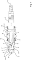
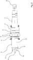
- a first embodiment of a spark plug according to the invention is shown.
- the spark plug is designed as a prechamber spark plug, it being expressly pointed out that the spark plug according to the invention does not necessarily have to be designed as a prechamber spark plug.
- the spark plug comprises a housing 1 which encloses part of an insulator 2.
- the housing 1 has a first housing part 3 and a second housing part 4.
- the housing parts 3, 4 are connected to one another via a weld 5.
- a supply line, not shown, runs inside the insulator 2, via which the central electrode 6 can be subjected to electrical voltage.
- the center electrode 6 is implemented in the form of two strips, each with ends curved in an arc. The ends of the strips each act as an ignition surface.
- the first housing part 3 serves as a ground electrode 7.
- the antechamber 8 is closed by a cap 9, with passage openings 10 in the cap 9 are formed through which the ignition torches can extend into the combustion chamber.
- the cap 9 is connected to the first housing part 3 via a weld 5 ′.
- a deformation area 11 is provided on the second housing part 4. To generate the deformation area 11, this area of the second housing part 4 is heated in an annular, homogeneous manner after the first housing part 3 and the second housing part 4 have been welded to one another. As soon as the deformation area 11 has a corresponding temperature - preferably above 600 ° C. - the housing parts 3, 4 are pressed against one another with a force F, preferably along the arrows shown in the figures. As a result of the cooling, the deformation region 11 shrinks, so that the insulator 2 is braced in the housing 3, 4, as is shown in the figures. In particular, it is conceivable that the deformation area 11 rests directly or indirectly on the insulator 2. It is expressly pointed out that the deformation area 11 can also be realized exclusively on the first housing part 3 or that at least one deformation area 11 can be formed on each of the two housing parts 3, 4.
- the end of the second housing part 4 facing away from the combustion chamber is particularly solid and robust, which significantly minimizes the risk of the insulator 2 being pushed out of the housing 1, in particular in comparison to a one-piece housing that is contained therein Area is beaded.
- a connection means 12 for connecting the supply line to an ignition system is formed.
- a ventilation opening 13 and an engagement means 14 are also formed.
- the attack means 14 is implemented as a hexagon.
- a sealing ring 15, for example made of steel or copper, is provided between the first housing part 3 and the insulator 2.
- a thread 16 and a further sealing ring 17, which seals with the combustion chamber cover are formed on the outer wall of the first housing part 3.
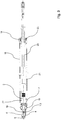
- FIG. 3 and 4th another embodiment of a spark plug according to the invention is shown.
- This corresponds essentially to the exemplary embodiment according to FIG Fig. 1 and 2 , with a housing extension 18 being connected to the first housing part 3 via a weld 19.
- An ignition line 20 runs inside the housing extension 18.
- the area between the ignition line 20 and the tubular housing extension 18 is filled with an electrically insulating material 21, for example a silicone gel, and sealed with a sealing ring 22.
- a passage 23 for the ignition line 20 is formed at the end of the housing extension 18 facing away from the combustion chamber.
- an engagement means 14 for a tool and a ventilation opening 13 are formed on the housing extension 18.
- the engagement means 14 can be a hexagon, for example, so that the spark plug can be screwed into the ignition chamber with a tool that is suitable for it.
Landscapes
- Engineering & Computer Science (AREA)
- Manufacturing & Machinery (AREA)
- Spark Plugs (AREA)
Claims (13)
- Bougie d'allumage, plus particulièrement bougie d'allumage de pré-chambre, avec un boîtier (1), une électrode centrale (6) et une électrode de masse (7), dans laquelle l'électrode centrale (6) peut être alimentée en tension électrique par l'intermédiaire d'une conduite d'alimentation s'étendant au moins partiellement dans un isolateur (2) et dans laquelle le boîtier (1) est constitué d'une première partie de boîtier (3) et d'une deuxième partie de boîtier (4) et loge en lui au moins une partie de l'isolateur (2) et dans laquelle la deuxième partie de boîtier (4), opposée à une chambre de combustion, comprend une zone de déformation (11) afin de serrer l'isolateur (2) à l'intérieur de la première partie de boîtier (3) et de la deuxième partie de boîtier (4), dans laquelle la zone de déformation (11) est générée par chauffage et compression de la première partie de boîtier (3) et de la deuxième partie de boîtier (4) le long de la direction axiale,
caractérisée en ce que l'extrémité de la deuxième partie de boîtier (4), opposée à la chambre de combustion, est réalisée de manière massive et en ce que la deuxième partie de boîtier s'accroche à l'arrière de l'isolateur (2) avec son extrémité opposée à la chambre de combustion. - Bougie d'allumage selon la revendication 1, caractérisée en ce que la zone de déformation (11) présente, contrairement à l'extrémité de la deuxième partie de boîtier (4), opposée à la chambre de combustion et réalisée de manière passive, une surface de section transversale réduite.
- Bougie d'allumage selon la revendication 1 ou 2, caractérisée en ce que la première partie de boîtier (3) et la deuxième partie de boîtier (4) sont constituées de matériaux différents.
- Bougie d'allumage selon l'une des revendications 1 à 3, caractérisée en ce que, sur la première partie de boîtier (3) et/ou sur la deuxième partie de boîtier (4), est réalisée au moins une ouverture de ventilation (13).
- Bougie d'allumage selon l'une des revendications 1 à 4, caractérisée en ce que la première partie de boîtier (3) et/ou la deuxième partie de boîtier (4) sont reliées entre elles par l'intermédiaire d'un cordon de soudure (5).
- Bougie d'allumage selon l'une des revendications 1 à 5, caractérisée en ce que, sur le boîtier (3, 4) est disposé un prolongement de boîtier tubulaire (18).
- Bougie d'allumage selon la revendication 6, caractérisée en ce que le prolongement de boîtier (18) est soudé avec le boîtier (3, 4).
- Bougie d'allumage selon la revendication 6 ou 7, caractérisée en ce que le prolongement de boîtier (18) comprend un passage (23) pour une conduite d'allumage (20).
- Bougie d'allumage selon l'une des revendications 6 à 8, caractérisée en ce que, sur le prolongement de boîtier (18) est réalisée au moins une ouverture de ventilation (13).
- Bougie d'allumage selon l'une des revendications 1 à 9, caractérisée en ce que, sur la première partie de boîtier (3) ou sur le prolongement de boîtier (18) est réalisé un moyen d'engagement (14), plus particulièrement un six-pans, pour un outil de montage.
- Procédé de fabrication d'une bougie d'allumage, plus particulièrement d'une bougie d'allumage de pré-chambre, de préférence selon l'une des revendications 1 à 10, avec les étapes suivantes :- disposition d'au moins une zone d'un isolateur (2) dans une première partie de boîtier (3) et une deuxième partie de boîtier (4), de façon à ce que l'extrémité de la deuxième partie de boîtier (4), opposée à la chambre de combustion et réalisée de manière massive, s'accroche à l'arrière de l'isolateur (2),- liaison de la première partie de boîtier (3) avec la deuxième partie de boîtier (4),- chauffage d'une zone de déformation (11) de la première partie de boîtier (3) et/ou de la deuxième partie de boîtier (4), de préférence à plus de 600°C et compression de la première partie de boîtier (3) et de la deuxième partie de boîtier (4) l'une contre l'autre le long de la direction axiale, de façon à ce que l'isolateur (2) soit serré à l'intérieur de la première partie de boîtier (3) et de la deuxième partie de boîtier (4).
- Procédé selon la revendication 11, caractérisé en ce que les parties de boîtier (3, 4) sont soudées entre elles, par exemple au moyen d'un procédé de soudure à électrode de tungstène et à gaz inerte ou d'un procédé de soudure au plasma ou d'un procédé de soudure au laser.
- Procédé selon la revendication 11 ou 12, caractérisé en ce que la zone de déformation (11) est chauffée au moyen d'un chauffage inductif.
Priority Applications (1)
| Application Number | Priority Date | Filing Date | Title |
|---|---|---|---|
| EP20198706.2A EP3771049B1 (fr) | 2017-02-13 | 2017-12-08 | Bougie d'allumage et procédé de fabrication d'une bougie d'allumage |
Applications Claiming Priority (2)
| Application Number | Priority Date | Filing Date | Title |
|---|---|---|---|
| DE102017202238.8A DE102017202238B3 (de) | 2017-02-13 | 2017-02-13 | Zündkerze und ein Verfahren zur Herstellung einer Zündkerze |
| PCT/DE2017/200132 WO2018145679A1 (fr) | 2017-02-13 | 2017-12-08 | Bougie d'allumage et procédé de fabrication d'une bougie d'allumage |
Related Child Applications (1)
| Application Number | Title | Priority Date | Filing Date |
|---|---|---|---|
| EP20198706.2A Division EP3771049B1 (fr) | 2017-02-13 | 2017-12-08 | Bougie d'allumage et procédé de fabrication d'une bougie d'allumage |
Publications (2)
| Publication Number | Publication Date |
|---|---|
| EP3406009A1 EP3406009A1 (fr) | 2018-11-28 |
| EP3406009B1 true EP3406009B1 (fr) | 2020-10-28 |
Family
ID=60996744
Family Applications (2)
| Application Number | Title | Priority Date | Filing Date |
|---|---|---|---|
| EP20198706.2A Active EP3771049B1 (fr) | 2017-02-13 | 2017-12-08 | Bougie d'allumage et procédé de fabrication d'une bougie d'allumage |
| EP17832910.8A Active EP3406009B1 (fr) | 2017-02-13 | 2017-12-08 | Bougie d'allumage et procédé de fabrication d'une bougie d'allumage |
Family Applications Before (1)
| Application Number | Title | Priority Date | Filing Date |
|---|---|---|---|
| EP20198706.2A Active EP3771049B1 (fr) | 2017-02-13 | 2017-12-08 | Bougie d'allumage et procédé de fabrication d'une bougie d'allumage |
Country Status (3)
| Country | Link |
|---|---|
| EP (2) | EP3771049B1 (fr) |
| DE (1) | DE102017202238B3 (fr) |
| WO (1) | WO2018145679A1 (fr) |
Families Citing this family (5)
| Publication number | Priority date | Publication date | Assignee | Title |
|---|---|---|---|---|
| DE102018206784A1 (de) * | 2018-05-03 | 2019-11-07 | Robert Bosch Gmbh | Vorkammer-Zündkerze |
| WO2022019022A1 (fr) | 2020-07-22 | 2022-01-27 | 株式会社デンソー | Bougie d'allumage pour moteur à combustion interne et son procédé de production |
| JP7468257B2 (ja) | 2020-09-02 | 2024-04-16 | 株式会社デンソー | 内燃機関用のスパークプラグ及びこれを備えた内燃機関 |
| DE102021203101A1 (de) | 2021-03-29 | 2022-09-29 | Dkt Verwaltungs-Gmbh | Zündkerze und ein Verfahren zur Herstellung einer Zündkerze |
| US11569640B2 (en) | 2021-06-23 | 2023-01-31 | Caterpillar Inc. | Spark plug |
Family Cites Families (8)
| Publication number | Priority date | Publication date | Assignee | Title |
|---|---|---|---|---|
| DE889386C (de) * | 1948-12-04 | 1953-09-10 | Gen Motors Corp | Zuendkerze fuer Verbrennungskraftmaschinen |
| US2863080A (en) * | 1955-04-15 | 1958-12-02 | Gen Motors Corp | Spark plug and method for making same |
| DE50303823D1 (de) * | 2002-02-22 | 2006-07-27 | Kuhnert Dieter | Vorkammerzündkerze und verfahren zur herstellung derselben |
| ES2235130T3 (es) * | 2002-07-22 | 2005-07-01 | Jenbacher Aktiengesellschaft | Bujia de encendido. |
| BRPI0714695A2 (pt) * | 2006-08-03 | 2013-05-14 | Federal Mogul Corp | vela de igniÇço |
| DE102006043593B3 (de) * | 2006-09-16 | 2008-04-10 | Multitorch Gmbh | Zündkerze |
| US8030831B1 (en) * | 2010-04-01 | 2011-10-04 | Fram Group Ip Llc | High thread spark plug with undercut insulator |
| JP2017004882A (ja) * | 2015-06-15 | 2017-01-05 | 富士重工業株式会社 | 点火プラグ |
-
2017
- 2017-02-13 DE DE102017202238.8A patent/DE102017202238B3/de active Active
- 2017-12-08 WO PCT/DE2017/200132 patent/WO2018145679A1/fr active Application Filing
- 2017-12-08 EP EP20198706.2A patent/EP3771049B1/fr active Active
- 2017-12-08 EP EP17832910.8A patent/EP3406009B1/fr active Active
Non-Patent Citations (1)
| Title |
|---|
| None * |
Also Published As
| Publication number | Publication date |
|---|---|
| DE102017202238B3 (de) | 2018-02-08 |
| EP3771049A1 (fr) | 2021-01-27 |
| WO2018145679A1 (fr) | 2018-08-16 |
| EP3406009A1 (fr) | 2018-11-28 |
| EP3771049B1 (fr) | 2022-06-22 |
Similar Documents
| Publication | Publication Date | Title |
|---|---|---|
| EP3406009B1 (fr) | Bougie d'allumage et procédé de fabrication d'une bougie d'allumage | |
| EP3281263B1 (fr) | Bougie d'allumage | |
| DE102015114453B4 (de) | Zündkerze für eine Brennkraftmaschine und Verfahren zur Herstellung einer Zündkerze | |
| DE102011012528B3 (de) | Vorkammerzündkerze | |
| EP2517323A1 (fr) | Bougie d'allumage munie d'un trou pour le réglage | |
| DE102017117452B4 (de) | Zündkerze und Verfahren zu ihrer Herstellung | |
| DE102004055218A1 (de) | Glühkerze und Verfahren zu ihrer Herstellung | |
| EP3281264B1 (fr) | Bougie d'allumage | |
| DE102010011739B4 (de) | Zündkerze und Verfahren zur Herstellung einer Zündkerze | |
| EP2608337B1 (fr) | Dispositif de manchon de raccordement de câble | |
| DE2809694A1 (de) | Verfahren zum herstellen einer zuendkerze | |
| DE102012100716B4 (de) | Herstellungsverfahren und Herstellungsvorrichtung für eine Zündkerze | |
| DE102012101168B4 (de) | Zündkerze | |
| EP4068536A1 (fr) | Bougie d'allumage de chambre de précombustion et procédé de fabrication d'une bougie d'allumage de chambre de précombustion | |
| DE112016005813T5 (de) | Zündkerze | |
| DE102018221917A1 (de) | Vorkammerzündkerze | |
| EP3127199B1 (fr) | Parafoudre | |
| DE102018222468A1 (de) | Zündkerze mit verrundetem Isolatorfuß-Abschnitt und verrundetem Gehäuse-Abschnitt | |
| EP2080253B1 (fr) | Eclateur a haute puissance, encapsule, resistant a la pression, etanche mais non hermetique et a symetrie de rotation | |
| EP1456922B1 (fr) | Dispositif et procede d'etanchement | |
| DE102004046895A1 (de) | Zündkerze und Verfahren zu deren Herstellung | |
| DE102020211352A1 (de) | Vorkammerzündkerze mit verbesserter Masseelektrode | |
| DE102015115550A1 (de) | Überspannungsableiter | |
| DE102023133962A1 (de) | Zündkerze für eine Brennkraftmaschine | |
| DE102021214623A1 (de) | Zündkerze mit dichtender Masseelektrode |
Legal Events
| Date | Code | Title | Description |
|---|---|---|---|
| STAA | Information on the status of an ep patent application or granted ep patent |
Free format text: STATUS: UNKNOWN |
|
| STAA | Information on the status of an ep patent application or granted ep patent |
Free format text: STATUS: THE INTERNATIONAL PUBLICATION HAS BEEN MADE |
|
| PUAI | Public reference made under article 153(3) epc to a published international application that has entered the european phase |
Free format text: ORIGINAL CODE: 0009012 |
|
| STAA | Information on the status of an ep patent application or granted ep patent |
Free format text: STATUS: REQUEST FOR EXAMINATION WAS MADE |
|
| 17P | Request for examination filed |
Effective date: 20180822 |
|
| AK | Designated contracting states |
Kind code of ref document: A1 Designated state(s): AL AT BE BG CH CY CZ DE DK EE ES FI FR GB GR HR HU IE IS IT LI LT LU LV MC MK MT NL NO PL PT RO RS SE SI SK SM TR |
|
| AX | Request for extension of the european patent |
Extension state: BA ME |
|
| DAV | Request for validation of the european patent (deleted) | ||
| DAX | Request for extension of the european patent (deleted) | ||
| GRAP | Despatch of communication of intention to grant a patent |
Free format text: ORIGINAL CODE: EPIDOSNIGR1 |
|
| STAA | Information on the status of an ep patent application or granted ep patent |
Free format text: STATUS: GRANT OF PATENT IS INTENDED |
|
| INTG | Intention to grant announced |
Effective date: 20200728 |
|
| GRAS | Grant fee paid |
Free format text: ORIGINAL CODE: EPIDOSNIGR3 |
|
| GRAA | (expected) grant |
Free format text: ORIGINAL CODE: 0009210 |
|
| STAA | Information on the status of an ep patent application or granted ep patent |
Free format text: STATUS: THE PATENT HAS BEEN GRANTED |
|
| AK | Designated contracting states |
Kind code of ref document: B1 Designated state(s): AL AT BE BG CH CY CZ DE DK EE ES FI FR GB GR HR HU IE IS IT LI LT LU LV MC MK MT NL NO PL PT RO RS SE SI SK SM TR |
|
| REG | Reference to a national code |
Ref country code: GB Ref legal event code: FG4D Free format text: NOT ENGLISH |
|
| REG | Reference to a national code |
Ref country code: CH Ref legal event code: EP |
|
| REG | Reference to a national code |
Ref country code: DE Ref legal event code: R096 Ref document number: 502017007977 Country of ref document: DE |
|
| REG | Reference to a national code |
Ref country code: AT Ref legal event code: REF Ref document number: 1329184 Country of ref document: AT Kind code of ref document: T Effective date: 20201115 |
|
| REG | Reference to a national code |
Ref country code: IE Ref legal event code: FG4D Free format text: LANGUAGE OF EP DOCUMENT: GERMAN |
|
| REG | Reference to a national code |
Ref country code: DE Ref legal event code: R082 Ref document number: 502017007977 Country of ref document: DE Representative=s name: PATENT- UND RECHTSANWAELTE ULLRICH & NAUMANN P, DE Ref country code: DE Ref legal event code: R081 Ref document number: 502017007977 Country of ref document: DE Owner name: DKT VERWALTUNGS-GMBH, DE Free format text: FORMER OWNER: DKT VERWALTUNGS-GMBH, 74889 SINSHEIM, DE |
|
| REG | Reference to a national code |
Ref country code: NL Ref legal event code: MP Effective date: 20201028 |
|
| RAP4 | Party data changed (patent owner data changed or rights of a patent transferred) |
Owner name: DKT VERWALTUNGS-GMBH |
|
| PG25 | Lapsed in a contracting state [announced via postgrant information from national office to epo] |
Ref country code: GR Free format text: LAPSE BECAUSE OF FAILURE TO SUBMIT A TRANSLATION OF THE DESCRIPTION OR TO PAY THE FEE WITHIN THE PRESCRIBED TIME-LIMIT Effective date: 20210129 Ref country code: NO Free format text: LAPSE BECAUSE OF FAILURE TO SUBMIT A TRANSLATION OF THE DESCRIPTION OR TO PAY THE FEE WITHIN THE PRESCRIBED TIME-LIMIT Effective date: 20210128 Ref country code: PT Free format text: LAPSE BECAUSE OF FAILURE TO SUBMIT A TRANSLATION OF THE DESCRIPTION OR TO PAY THE FEE WITHIN THE PRESCRIBED TIME-LIMIT Effective date: 20210301 Ref country code: RS Free format text: LAPSE BECAUSE OF FAILURE TO SUBMIT A TRANSLATION OF THE DESCRIPTION OR TO PAY THE FEE WITHIN THE PRESCRIBED TIME-LIMIT Effective date: 20201028 Ref country code: FI Free format text: LAPSE BECAUSE OF FAILURE TO SUBMIT A TRANSLATION OF THE DESCRIPTION OR TO PAY THE FEE WITHIN THE PRESCRIBED TIME-LIMIT Effective date: 20201028 |
|
| REG | Reference to a national code |
Ref country code: LT Ref legal event code: MG4D |
|
| PG25 | Lapsed in a contracting state [announced via postgrant information from national office to epo] |
Ref country code: ES Free format text: LAPSE BECAUSE OF FAILURE TO SUBMIT A TRANSLATION OF THE DESCRIPTION OR TO PAY THE FEE WITHIN THE PRESCRIBED TIME-LIMIT Effective date: 20201028 Ref country code: SE Free format text: LAPSE BECAUSE OF FAILURE TO SUBMIT A TRANSLATION OF THE DESCRIPTION OR TO PAY THE FEE WITHIN THE PRESCRIBED TIME-LIMIT Effective date: 20201028 Ref country code: PL Free format text: LAPSE BECAUSE OF FAILURE TO SUBMIT A TRANSLATION OF THE DESCRIPTION OR TO PAY THE FEE WITHIN THE PRESCRIBED TIME-LIMIT Effective date: 20201028 Ref country code: IS Free format text: LAPSE BECAUSE OF FAILURE TO SUBMIT A TRANSLATION OF THE DESCRIPTION OR TO PAY THE FEE WITHIN THE PRESCRIBED TIME-LIMIT Effective date: 20210228 Ref country code: LV Free format text: LAPSE BECAUSE OF FAILURE TO SUBMIT A TRANSLATION OF THE DESCRIPTION OR TO PAY THE FEE WITHIN THE PRESCRIBED TIME-LIMIT Effective date: 20201028 Ref country code: BG Free format text: LAPSE BECAUSE OF FAILURE TO SUBMIT A TRANSLATION OF THE DESCRIPTION OR TO PAY THE FEE WITHIN THE PRESCRIBED TIME-LIMIT Effective date: 20210128 |
|
| PG25 | Lapsed in a contracting state [announced via postgrant information from national office to epo] |
Ref country code: HR Free format text: LAPSE BECAUSE OF FAILURE TO SUBMIT A TRANSLATION OF THE DESCRIPTION OR TO PAY THE FEE WITHIN THE PRESCRIBED TIME-LIMIT Effective date: 20201028 Ref country code: NL Free format text: LAPSE BECAUSE OF FAILURE TO SUBMIT A TRANSLATION OF THE DESCRIPTION OR TO PAY THE FEE WITHIN THE PRESCRIBED TIME-LIMIT Effective date: 20201028 |
|
| REG | Reference to a national code |
Ref country code: DE Ref legal event code: R097 Ref document number: 502017007977 Country of ref document: DE |
|
| PG25 | Lapsed in a contracting state [announced via postgrant information from national office to epo] |
Ref country code: SM Free format text: LAPSE BECAUSE OF FAILURE TO SUBMIT A TRANSLATION OF THE DESCRIPTION OR TO PAY THE FEE WITHIN THE PRESCRIBED TIME-LIMIT Effective date: 20201028 Ref country code: LT Free format text: LAPSE BECAUSE OF FAILURE TO SUBMIT A TRANSLATION OF THE DESCRIPTION OR TO PAY THE FEE WITHIN THE PRESCRIBED TIME-LIMIT Effective date: 20201028 Ref country code: CZ Free format text: LAPSE BECAUSE OF FAILURE TO SUBMIT A TRANSLATION OF THE DESCRIPTION OR TO PAY THE FEE WITHIN THE PRESCRIBED TIME-LIMIT Effective date: 20201028 Ref country code: EE Free format text: LAPSE BECAUSE OF FAILURE TO SUBMIT A TRANSLATION OF THE DESCRIPTION OR TO PAY THE FEE WITHIN THE PRESCRIBED TIME-LIMIT Effective date: 20201028 Ref country code: RO Free format text: LAPSE BECAUSE OF FAILURE TO SUBMIT A TRANSLATION OF THE DESCRIPTION OR TO PAY THE FEE WITHIN THE PRESCRIBED TIME-LIMIT Effective date: 20201028 Ref country code: SK Free format text: LAPSE BECAUSE OF FAILURE TO SUBMIT A TRANSLATION OF THE DESCRIPTION OR TO PAY THE FEE WITHIN THE PRESCRIBED TIME-LIMIT Effective date: 20201028 |
|
| REG | Reference to a national code |
Ref country code: CH Ref legal event code: PL |
|
| PG25 | Lapsed in a contracting state [announced via postgrant information from national office to epo] |
Ref country code: DK Free format text: LAPSE BECAUSE OF FAILURE TO SUBMIT A TRANSLATION OF THE DESCRIPTION OR TO PAY THE FEE WITHIN THE PRESCRIBED TIME-LIMIT Effective date: 20201028 Ref country code: MC Free format text: LAPSE BECAUSE OF FAILURE TO SUBMIT A TRANSLATION OF THE DESCRIPTION OR TO PAY THE FEE WITHIN THE PRESCRIBED TIME-LIMIT Effective date: 20201028 |
|
| PLBE | No opposition filed within time limit |
Free format text: ORIGINAL CODE: 0009261 |
|
| REG | Reference to a national code |
Ref country code: BE Ref legal event code: MM Effective date: 20201231 |
|
| STAA | Information on the status of an ep patent application or granted ep patent |
Free format text: STATUS: NO OPPOSITION FILED WITHIN TIME LIMIT |
|
| 26N | No opposition filed |
Effective date: 20210729 |
|
| PG25 | Lapsed in a contracting state [announced via postgrant information from national office to epo] |
Ref country code: AL Free format text: LAPSE BECAUSE OF FAILURE TO SUBMIT A TRANSLATION OF THE DESCRIPTION OR TO PAY THE FEE WITHIN THE PRESCRIBED TIME-LIMIT Effective date: 20201028 Ref country code: LU Free format text: LAPSE BECAUSE OF NON-PAYMENT OF DUE FEES Effective date: 20201208 Ref country code: IT Free format text: LAPSE BECAUSE OF FAILURE TO SUBMIT A TRANSLATION OF THE DESCRIPTION OR TO PAY THE FEE WITHIN THE PRESCRIBED TIME-LIMIT Effective date: 20201028 Ref country code: IE Free format text: LAPSE BECAUSE OF NON-PAYMENT OF DUE FEES Effective date: 20201208 |
|
| PG25 | Lapsed in a contracting state [announced via postgrant information from national office to epo] |
Ref country code: CH Free format text: LAPSE BECAUSE OF NON-PAYMENT OF DUE FEES Effective date: 20201231 Ref country code: SI Free format text: LAPSE BECAUSE OF FAILURE TO SUBMIT A TRANSLATION OF THE DESCRIPTION OR TO PAY THE FEE WITHIN THE PRESCRIBED TIME-LIMIT Effective date: 20201028 Ref country code: LI Free format text: LAPSE BECAUSE OF NON-PAYMENT OF DUE FEES Effective date: 20201231 |
|
| PG25 | Lapsed in a contracting state [announced via postgrant information from national office to epo] |
Ref country code: IS Free format text: LAPSE BECAUSE OF FAILURE TO SUBMIT A TRANSLATION OF THE DESCRIPTION OR TO PAY THE FEE WITHIN THE PRESCRIBED TIME-LIMIT Effective date: 20210228 Ref country code: TR Free format text: LAPSE BECAUSE OF FAILURE TO SUBMIT A TRANSLATION OF THE DESCRIPTION OR TO PAY THE FEE WITHIN THE PRESCRIBED TIME-LIMIT Effective date: 20201028 Ref country code: MT Free format text: LAPSE BECAUSE OF FAILURE TO SUBMIT A TRANSLATION OF THE DESCRIPTION OR TO PAY THE FEE WITHIN THE PRESCRIBED TIME-LIMIT Effective date: 20201028 Ref country code: CY Free format text: LAPSE BECAUSE OF FAILURE TO SUBMIT A TRANSLATION OF THE DESCRIPTION OR TO PAY THE FEE WITHIN THE PRESCRIBED TIME-LIMIT Effective date: 20201028 |
|
| PG25 | Lapsed in a contracting state [announced via postgrant information from national office to epo] |
Ref country code: MK Free format text: LAPSE BECAUSE OF FAILURE TO SUBMIT A TRANSLATION OF THE DESCRIPTION OR TO PAY THE FEE WITHIN THE PRESCRIBED TIME-LIMIT Effective date: 20201028 |
|
| PG25 | Lapsed in a contracting state [announced via postgrant information from national office to epo] |
Ref country code: BE Free format text: LAPSE BECAUSE OF NON-PAYMENT OF DUE FEES Effective date: 20201231 |
|
| GBPC | Gb: european patent ceased through non-payment of renewal fee |
Effective date: 20211208 |
|
| PG25 | Lapsed in a contracting state [announced via postgrant information from national office to epo] |
Ref country code: GB Free format text: LAPSE BECAUSE OF NON-PAYMENT OF DUE FEES Effective date: 20211208 |
|
| P01 | Opt-out of the competence of the unified patent court (upc) registered |
Effective date: 20230522 |
|
| PGFP | Annual fee paid to national office [announced via postgrant information from national office to epo] |
Ref country code: FR Payment date: 20231220 Year of fee payment: 7 Ref country code: AT Payment date: 20231214 Year of fee payment: 7 |
|
| PGFP | Annual fee paid to national office [announced via postgrant information from national office to epo] |
Ref country code: DE Payment date: 20240227 Year of fee payment: 7 |