EP3402678B1 - Déverrouillage de l'accouplement d'une roue dentée double - Google Patents
Déverrouillage de l'accouplement d'une roue dentée double Download PDFInfo
- Publication number
- EP3402678B1 EP3402678B1 EP17702301.7A EP17702301A EP3402678B1 EP 3402678 B1 EP3402678 B1 EP 3402678B1 EP 17702301 A EP17702301 A EP 17702301A EP 3402678 B1 EP3402678 B1 EP 3402678B1
- Authority
- EP
- European Patent Office
- Prior art keywords
- cylinder
- annular
- ring
- gear
- clamping
- Prior art date
- Legal status (The legal status is an assumption and is not a legal conclusion. Google has not performed a legal analysis and makes no representation as to the accuracy of the status listed.)
- Active
Links
Images


Classifications
-
- B—PERFORMING OPERATIONS; TRANSPORTING
- B41—PRINTING; LINING MACHINES; TYPEWRITERS; STAMPS
- B41F—PRINTING MACHINES OR PRESSES
- B41F13/00—Common details of rotary presses or machines
- B41F13/008—Mechanical features of drives, e.g. gears, clutches
-
- B—PERFORMING OPERATIONS; TRANSPORTING
- B41—PRINTING; LINING MACHINES; TYPEWRITERS; STAMPS
- B41P—INDEXING SCHEME RELATING TO PRINTING, LINING MACHINES, TYPEWRITERS, AND TO STAMPS
- B41P2213/00—Arrangements for actuating or driving printing presses; Auxiliary devices or processes
- B41P2213/10—Constitutive elements of driving devices
- B41P2213/25—Couplings; Clutches
- B41P2213/254—Devices allowing two gears to engage with each other
Definitions
- the invention relates to a device for releasing a frictional connection according to the preamble of patent claim 1.
- a so-called sheet turning device is arranged in the transport path of the printed sheet for the purpose of accomplishing the use of the sheet. Normally, the sheet is transported with its leading edge through the entire machine, in which case only the top of the sheet is printed. If the sheet is to be printed from both sides, the sheet turning device is switched between two printing units, as a result of which there is the trailing edge of the sheet to the leading edge.
- the relative position of the adjacent printing units is to change so that at this point instead of the leading edge of the sheet now the trailing edge can be passed.
- To change the relative position of the gear train is in such a printing machine by means of a double-coupled double gear (on a main gear a ring gear is rotatably arranged) equipped with clamping devices.
- the clamping devices may include a clamping ring and are stretched and unlocked via curves or spring sets.
- a device of this type describes the DE-PS 35 34 488 ,
- the clamping force is applied by a spring which can be charged to cancel the clamping of a pneumatic piston or bellows.
- the clamping is done by means of one-armed cranked levers, which are connected via bolts with the clamps for clamping the gear ring.
- the one-armed, cranked levers are mounted on ball elements and generate at the point of articulation of the bolt in their Movement an axial displacement with respect to the clamping claws. As a result, a clamping force is applied to the clamping claws with the pivotal movement of the lever.
- the pivotal movement of the lever is generated by a guide body in which engage the ends of the lever.
- the guide body sits on a rod centric to the main gear.
- the rod is axially slidably connected to the drive pin of the gear and is loaded by a compression spring to the outside.
- the outer end of the guide rod around.
- the power transmission is very complicated solved.
- Another problem can be seen that the bellows is supported against the force of the compression spring between the housing wall and the cylinder.
- an axial force is applied to the cylinder bearings which can lead to a displacement of the entire cylinder and thus the gears.
- a coupling device for effecting a temporary decoupling of the sections of a gear train of a printing press is known.
- the coupling device for carrying out a change of the phase position of the respective gear portions serving each other adjustment process should be characterized by a robust construction and a reliable high torque transfer.
- the coupling device is coaxially provided with a first and second spur gear.
- a clamping device serves to generate one of the frictional transmission of a torque between the first and the second spur gear.
- a chamber device is used for applying a clamping force bringing the clamping device in a release state.
- a clamping plate is arranged, which is resiliently biased in a basic position and generates the necessary clamping force for the clutch engagement.
- a coupling device for effecting a temporary decoupling of the sections of a gear train of a printing press according to the preamble of claim 1 is known.
- the coupling device is used for the temporary separation of a gear train of a printing machine for processing a change in the phase position of portions of the gear train.
- a first and a second spur gear are clamped by a clamping device for the frictional transmission of torque.
- a force is applied by a pressure medium via a chamber device, wherein the chamber device is formed by a first ring member and a second, with respect to the first ring member axially displaceable ring member.
- the first ring element has a disengaging contact section which is set against a resiliently supported component in order to move the clamping device into a release state.
- the second ring element has a support abutment portion which is seated in the release state on a coupled with the first spur support shoulder.
- DE 36 11 324 A1 DE 197 18 140 C1 and DE 35 34 488 A1 described.
- the device aligns itself on the gear and has no contact with the double gear during normal operation.
- the unlocking mechanism consists of a rectangular in cross-section and formed by two concentric rings circular Hubkanal in which a lifting ring is displaced by means of a fluidically generated drive energy against the rings of the Hubkanals. During the displacement, the rings are supported on elements of the double gear so that the clamping of the gear ring is canceled.
- the described variants use hydraulic or pneumatic energy.
- the force applied to unlock the clamping of the gear ring on the main gear is diverted within the double gear and thereby a rigid axial bearing of the printing cylinder can act supported. This also results in no shifts z. B. could lead to a rotational displacement of the drive in a helical gearing.
- the unlocking system is not in the normal machine operation with the double gear in touch. At the double gear itself no additional elements are required, so that the mass of the double gear is not increased. The double gear itself is so completely maintenance-free and the clutch to cancel the clamping of the double gear is to be maintained without changes to this or built and removed.
- the second spur gear is clamped by loaded by spring tension tie rods on the first spur gear.
- the device is arranged symmetrically to the axis of the double gear and has for releasing at least one annular fluid-operated lifting arrangement. This is coupled to the machine frame and at least partially displaceable in the direction of an axis of the double gear.
- the lifting arrangement connects in the release position a part of the double gear to the machine frame.
- the cylinder pin is received in a cylinder bearing, in which an axial bearing arranged separately from a radial bearing is provided.
- the annular fluid operated lift assembly is disposed directly adjacent and concentric with the axial support on the machine frame of the sheet-fed rotary printing machine.
- a pressure element of the lifting arrangement is assigned to a respective pressure element transmitting the spring force to a respective tie rod.
- the annular lifting arrangement is formed from a ring cylinder and an annular piston arranged in this ring opening.
- the ring cylinder is arranged coaxially with the axis of the double gear and directly adjacent parallel to an outer periphery of a guide ring of the axial bearing of the cylinder bearing on the machine frame.
- the annular piston is arranged to be movable parallel to the axis in the direction of and to the machine frame to the double gear.
- annular piston is formed as insertable into a front side of the machine frame facing away open piston chamber insert with sealing inserts on the inner and the outer edge.
- the annular piston is assigned a retaining device which is arranged within the piston chamber and which does not influence the annular piston in its lifting movement but which is secured in its peripheral position relative to the annular cylinder.
- the ring cylinder is arranged fixedly connected to the machine frame.
- a support ring is provided in mechanical connection with the ring cylinder and the directly adjacent region of the double gear as Kraftleitelement.
- the support ring is preferably coupled with the ring cylinder and engages behind a further arranged on the double gear retaining ring.
- each tie rod is assigned a respective pressure piece at a head end, which is opposite to a clamping screw at the other end of the tie rod.
- the pressure piece is used to apply force to a respectively associated with the tie rod spring assembly.
- the thrust pieces of all tie rods are arranged so that they touch the ring piston in its stroke position.
- a spring plate between a clamping ring and a cylinder-fixed element of the double gear is arranged.
- the spring plate dissolves the clamping ring when canceling the clamping of the clamping ring against a cylinder-fixed part of the double gear and is designed as an annular spring element.
- one or more return springs are arranged on the annular piston in such a manner that the annular piston is pushed into the piston chamber when the annular cylinder is relieved of pressure under the force of the return springs.
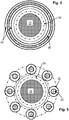
- the annular lifting element is formed from a plurality of lifting cylinders and in each case one lifting piston arranged in these.
- the lifting cylinders are arranged concentrically with respect to the cylindrical pin annular.
- FIG. 1 schematically a section of a sheet-fed rotary printing machine is shown.
- Two printing units 1A and 1B are by printing cylinders 2, 3 and sheet transport drums 4, 5 interconnected.
- the drive of the printing units is carried by gears which are coaxial with the printing cylinders 2, 3 and sheet transport drums 4, 5 are arranged.
- the sheet transport drum 5 is formed as a so-called turning drum. For the turning operation, the relative position of the two printing units 1A, 1B to each other in the circumferential direction by the amount of the length of the sheet to be printed to change, so that the sheet end can be transferred instead of the beginning of the sheet.
- the double gear 6 consists of a main gear 8 and a gear ring 9.
- the main gear 8 is connected to a cylinder pin 10.
- a clamping connection via a clamping ring 11 is produced between the fixed to the main gear 8 clamping ring 11 and the gear ring 9 clamping elements 12 under the force of spring assemblies 13 from. If the spring assemblies 13 are unloaded from the outside, they clamp the clamping element 12 against the clamping ring 11 and connect the ring gear 9 frictionally connected to the main gear 8.
- the drive torque is transmitted from a gear 14 via the ring gear 9 to the main gear 8 and from there on in Gear train downstream drive elements passed.
- the sheet transport elements are adjusted relative to each other after releasing the clamping of the gear ring 9, wherein the clamping force of the clamping elements 12 between clamping ring 11 and Gear ring 9 is canceled.
- This is effected with the double-wheel clutch 7, which consists of an inner ring 15 and an outer ring 16.
- the rings 15, 16 form a hydraulic or pneumatic system with a pressure chamber 28, which is sealed with seals 25 and to which a fluid is supplied through a pressure medium connection 27.
- the unlocking system is loaded by springs 18 engaging in the ring 15 engaging retaining pin 17 axially displaceable against a fixed support 20 as a rest position.
- the outer ring 16 abuts with a stop surface 21 under load of compression springs 19 on the inner ring 15.
- the outer end face 22 of the inner ring 15 and a bent annular face 23 of the outer ring 16 are used as effective surfaces of the system.
- an unlocking element 24 which is connected to the gear ring 9.
- the Doppelradkupplung 7 is positioned on the carrier 20 which is rigidly connected to a part of the machine frame 26.
- the release system In the unlocked state, the release system is free from fixed supports to small spring forces. Upon further supply of pressure medium, the clamping of the gear parts is canceled, without axial forces in the main gear 8 and its storage are introduced. The main gear 8 can be rotated relative to the gear ring 9, while the gear ring 9 and coupled to him gear parts are held.
- the unlocking system is depressurized and is by means of the springs 18, 19 back to its original position.
- FIG. 3 an embodiment of an unlocking device is shown on a double gear 6, which is not covered by the claims.
- the impression cylinder 2 is received with its cylindrical pin 10 via a radial bearing 32 guided in a bearing sleeve 33 and via a thrust bearing 34 guided in the machine side wall 26 on a guide ring 35.
- the guide ring 35 of the thrust bearing 34 is in this case attached from the outside to the machine side wall 26 and defines the entire bearing unit of the cylinder pin 10 immovably in this position.
- a gear main body 39 is fixed by means of a mounting plate 36.
- a first spur gear 8 is mounted rotationally.
- a second spur gear 9 is mounted as a gear ring on the gear main body 39 in parallel and coaxial with the first spur gear 8.
- a clamping ring 37 is arranged on the side facing away from the machine side wall 26 side. The clamping ring 37 is pressed by a tie rod 29 or more distributed over the circumference of the double gear 6 tie rods 29 against the first spur gear 8.
- each of the tie rods 29 passes through the first spur gear 8, the gear main body 39 and the clamping ring 37 and is supported, each with its own head-mounted pressure piece 31 against a respective spring assembly 13 (such as disc springs).
- a respective spring assembly 13 such as disc springs.
- Each of the spring assemblies 13 is received in corresponding devices on the first spur gear 8.
- Each tie rod 29 is further supported against the force of the spring pact 13 by a clamping nut 30, which is supported on the clamping ring 39, adjustable.
- annular spring plate 38 is arranged, which is shaped plate-shaped in the manner of a washer and is therefore biased during clamping between the clamping ring 37 and the gear main body 39. Therefore, the spring plate 38 when reducing or canceling the bias of the tie rods 29, the clamping ring 37 lift by a bulge of the gear ring of the second spur gear 9, so that it is movable relative to the first spur gear 8.
- This device consists of an annular cylinder (ring cylinder 40) which is arranged coaxially with the cylinder pin 10 in the immediate vicinity of the thrust bearing 34 on the machine side wall 26.
- ring cylinder 40 In the ring cylinder 40 is a Ring piston 41 under fluid supply or removal axially parallel to the cylinder pin 10 arranged displaceably.
- the annular piston 41 With fluid supply to the annular cylinder 40, the annular piston 41 is moved parallel to the axis of the cylinder pin 10 away from the machine side wall 26 and displaced against the plungers 31 of the tie rods 29. With appropriate pressure build-up, the annular piston 41 then presses together the spring assemblies 13 via the pressure pieces 31, so that the preload load that has been applied to the clamping ring 37 via the clamping nuts 30 is reduced or eliminated. Thereby, and by the return action of the spring plate 38, the second annular spur gear 9 is free and can be adjusted relative to the first spur gear 8.
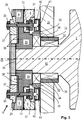
- FIG. 4 A corresponding representation of the annular cylinder 40 in association with the cylinder pin 10 and its axial bearing 34 (dash-dot line) is in FIG. 4 shown, wherein the annular piston 41 is shown hatched for better visibility.
- each of these lifting cylinders 42 with their reciprocating piston 43 is such that they are each a respective tie rod 29 and its pressure piece 31 are positioned opposite to the machine side wall 26.
- a device for exact positioning of the double gear 6 must be provided in its rotational position.
- a precisely aligned action of each of the reciprocating piston 43 to the respective associated tie rod 29 and its respective pressure piece 31 is required.
- annular piston 43 arranged around the cylinder pin 10 and its storage also by an all reciprocating 43 overlapping and the tie rods 29 and the pressure pieces 31 opposite arranged intermediate ring are synchronized in their effect to unlock the Zahnradklemmung.
- FIG. 6 is a structurally simple embodiment of the device according to the invention FIG. 3 in conjunction with a bearing arrangement with separate axial and radial guidance for the drivable by means of the double gear 6 pressure cylinder 2, in which the unlocking device 7 is assigned directly to a thrust bearing 34 on the cylinder pin 10.
- the cylindrical pin 10 is received in the machine side wall 26 via the radial bearing 32 guided in the bearing sleeve 33 and the axial bearing 34 guided on the guide ring 35, whereby the guide ring 35 secures the axial bearing 34 on the outside of the machine side wall 26 and the cylinder pin 10 in this position in the axial direction fixed immovably.
- a gear base body 39 is fixed with a mounting plate 36.
- gear main body 39 On gear main body 39, a first spur gear 8 is mounted rotationally. Parallel and coaxial with the first spur gear 8, the second spur gear 9 is mounted as a gear ring on the gear main body 39.
- the annular spur gear 9 is fixed to the first spur gear 8 by a clamping ring 37 is disposed on the gear base body 39 on the side remote from the machine side wall 26, which is distributed by tie rods 29 on the circumference of the double gear 6 against the first spur gear 8 pressed.
- Each tie rod 29 passes through the first spur gear 8, the gear main body 39 and the clamping ring 37 and is supported with a stepped head 29A in each one of the support load distributing pressure piece 31 against a spring assembly 13, which is received in the first spur gear 8.
- Each tie rod 29 is biased on the head 29A opposite side of a clamping nut 30, which is supported on the clamping ring 39, adjustable against the force of the spring pact 13 to the clamping ring 39 with the annular spur gear 9 and the annular spur gear 9 with the fixed To connect spur 8 frictionally.
- an annular spring plate 38 is arranged.
- annular cylinder (ring cylinder 40) is arranged coaxially with the cylinder pin 10 in the immediate vicinity of the thrust bearing 34 on the machine side wall 26.
- the ring cylinder 40 is fixedly connected to the machine side wall 26 and surrounds the guide ring 35 of the thrust bearing 34 in the radial direction without spacing.
- annular piston 41 is arranged under fluid supply or - removal axially parallel to the cylinder pin 10 displaced. With fluid supply to the annular cylinder 40 of the annular piston 41 is moved parallel to the axis 44 of the cylinder pin 10 away from the machine side wall 26 and displaced against the plungers 31 of the tie rods 29.
- a support of the introduction of force on the double gear 6 is provided.
- a support ring 45 is attached to the ring cylinder 40, which preferably engages behind the ring cylinder 40 at its base and is bent on the side of the annular piston 41.
- the support ring 45 protrudes into a recess on the spur gear 8, which is covered by a retaining ring 46.
- the second annular spur gear 9 is released with high positional accuracy in its clamping position and can then adjusted in its recording on the gear base 39 and relative to the first spur gear 8 with equally high accuracy become.
- annular cylinder 40 is fixedly connected to the frame side wall 26.
- the annular cylinder 40 is fixedly connected to the frame side wall 26.
- a safe and well-supported force is given by the integrative proximity between the thrust bearing 34 of the cylinder bearing and the ring cylinder 40 of the unlocking mechanism.
- the ring cylinder 40 in conjunction with the annular piston 41 is very simple and easy to install and also designed as an extremely compact arrangement.
- the annular piston 41 is an insert element with an overlapping edge as a stop and a sealing system 41A in the axial direction to the cylinder pin 10 in an annular piston chamber 40A inside the annular cylinder 40 inserted pushed. This ensures a very simple operation and easy maintenance of the machine.
- the annular piston 41 can be loaded at the abovementioned overlapping edge with a few return springs 46 in the direction of the machine frame 26, so that it safely returns to the basic position in the ring cylinder 40 when pressure is released.
- FIG. 6A the basic position of the annular piston 41 is shown with minimum distance to the pressure piece 31 on the tie rod 29 under load by the return springs 46.
- the return springs 46 may be arranged in any free access position to the annular piston 41 and must be secured to the machine frame 26 connected.
- the annular piston 41 can for securing against unintentional displacement in the circumferential direction with a loosely engaging in a recess 41 C in the piston crown locking pin 41 B (see FIG. 6A ).
- the annular piston 41 is not obstructed by the securing pin 41B with respect to the function to be performed for unlocking in the form of a lifting movement.
- tie rods 29 are charged themselves, but that the force for unlocking via a this at the remote head 29A associated pressure piece 31 is introduced to a respective associated spring assembly 13.
- the tie rods 29 are therefore not overstressed and can not be moved under a direct action of the annular piston 41, which could lead to unintentional displacements.
Landscapes
- Engineering & Computer Science (AREA)
- Mechanical Engineering (AREA)
- Rotary Presses (AREA)
- Gear Transmission (AREA)
- Supply, Installation And Extraction Of Printed Sheets Or Plates (AREA)
Claims (9)
- Dispositif de déverrouillage d'une connexion établie par correspondance géométrique d'un premier pignon droit (8) disposé sur un tourillon cylindrique (10) d'un cylindre de machine d'impression (2) et d'un double engrenage (6) composé d'un second pignon droit (9) associé à ce premier pignon droit (8) dans une machine rotative d'impression de feuilles pouvant être permutée d'une impression recto à une impression recto et verso, dans lequel le second pignon droit (9) est serré par une ancre de traction (29) chargée par force de ressort au niveau du premier pignon droit (8) et le dispositif de déverrouillage est disposé symétriquement à l'axe (44) du double engrenage (6), le dispositif présentant au moins un dispositif de levage (40, 41) de forme annulaire fonctionnant au fluide, qui présente une connexion avec un bâti de machine (26) et est fixé de manière à être déplaçable du moins partiellement en direction d'un axe (44) du double engrenage (6 ; 8, 9), le dispositif de levage (40, 41), dans une position de déverrouillage, connectant une partie du double engrenage (6 ; 8, 9) au bâti de machine (26) de manière fixe en rotation, le tourillon cylindrique (10) étant reçu dans un palier cylindrique dans lequel il est prévu un palier axial (34) disposé séparément d'un palier radial (32), le dispositif de levage (40, 41) de forme annulaire fonctionnant au fluide étant disposé de manière à être directement adjacent et concentrique au palier axial (34) au niveau du bâti de machine (26) de la machine rotative d'impression de feuilles,
un élément de pression du dispositif de levage (40, 41) étant chaque fois associé à une pièce de pression (31) disposée coaxialement par rapport à l'ancre de traction (29) et transférant la force de ressort sur une ancre de traction respective (29), de manière à ce que les forces de ressort agissant sur l'ancre/les ancres de traction (29) soient réduite ou suspendues sous charge par l'élément de pression,
le dispositif de levage de forme annulaire étant constitué d'un cylindre annulaire (40) et d'un piston annulaire (41) disposé dans un orifice annulaire du cylindre annulaire (40),
le cylindre annulaire (40) étant disposé coaxialement par rapport à l'axe (44) du double engrenage (6) et de manière à être directement parallèle et adjacent à la circonférence extérieure d'une bague de guidage (35) du palier axial (34) du palier cylindrique au niveau du bâti de machine (26) et
le piston annulaire (41) étant disposé de manière à être mobile parallèlement à l'axe (44) en direction du et vers le bâti de machine (26) par rapport au double engrenage (6),
une bague de soutien (45) étant prévue en connexion mécanique avec le cylindre annulaire (40) et la zone directement voisine du double engrenage (6) en tant qu'élément de conduction de force,
caractérisé en ce que la bague de soutien (45) est couplée au cylindre annulaire (40), de préférence en le saisissant par l'arrière, et que la bague de soutien (45) est en outre disposé au niveau d'une bague de retenue (46) disposée au niveau du double engrenage (6) en le saisissant par derrière. - Dispositif selon la revendication 1, caractérisé en ce que le piston annulaire (41) est réalisé sous forme d'un insert pouvant être introduit dans un espace de piston (40A) ouvert de forme annulaire détournée à l'avant du bâti de machine (26) du cylindre annulaire (40) et comportant des joints (41B) au niveau du flanc intérieur et extérieur.
- Dispositif selon une ou plusieurs des revendications 1 à 2, caractérisé en ce qu'est associé au piston annulaire (41) un dispositif de retenue (41A) disposé à l'intérieur de l'espace de piston (40A), connecté au cylindre annulaire (40) et n'influant pas sur le piston annulaire (41) dans son mouvement de levage mais le bloquant dans sa position circonférentielle par rapport au cylindre annulaire (40).
- Dispositif selon une ou plusieurs des revendications 1 à 3,
caractérisé
en ce que le cylindre annulaire (40) est disposé de manière à être connecté fixement au bâti de machine (26) . - Dispositif selon une ou plusieurs des revendications 1 à 4,
caractérisé
en ce qu'est associée à chaque ancre de traction (29) chaque fois une pièce de pression (31) à une extrémité sommitale qui est disposée à l'opposé d'une vis de serrage (30) à l'autre extrémité de l'ancre de traction (29) pour la conduction de force sur un pack de ressorts (13) respectivement associé à l'ancre de traction (29). - Dispositif selon une ou plusieurs des revendications 1 à 5,
caractérisé
en ce que les pièces de pression (31) de toutes les ancres de traction (29) sont associées au piston annulaire (41) dans sa position de levage dans la fonction de déverrouillage du serrage des pignons droits (8, 9) par l'élément de pression du dispositif de levage et que les pièces de pression (31) de toutes les ancres de traction (29) du piston annulaire (41) dans sa position de repos, dans la fonction de déblocage du serrage des pignons droits (8, 9) par l'élément de pression ne sont pas associées par contact au dispositif de levage. - Dispositif selon une ou plusieurs des revendications 1 à 6,
caractérisé
en ce qu'une plaque à ressort (38) est disposée entre une bague de serrage (37) et un élément fixe sur le cylindre du double engrenage (6) en tant que bague de serrage (37) en cas de suspension du serrage de la bague de serrage (37) contre un élément à ressort de forme circulaire relâchant une partie fixe sur le cylindre du double engrenage (6) . - Dispositif selon une ou plusieurs des revendications 1 à 7,
caractérisé
en ce qu'un ou plusieurs ressorts de rappel sont disposés en prise avec le piston annulaire (41), que le piston annulaire (41), en cas de relâchement de la pression du cylindre annulaire (40) sous la force des ressorts de rappel, est poussé dans l'espace de piston (40A) jusque contre une butée. - Dispositif selon une ou plusieurs des revendications 1 à 8,
caractérisé
en ce que le dispositif de levage de forme annulaire est composé de plusieurs cylindres de levage (42) et respectivement d'un piston de levage (43) disposée dans ceux-ci, que les cylindres de levage (42) sont disposés en forme annulaire concentriquement par rapport au tourillon cylindrique (10) et à l'axe (44) du double engrenage (6), chaque cylindre de levage (42) étant disposé fixement sur le bâti au niveau du châssis de la machine (26) et le piston annulaire respectif (43) étant disposé de manière à être mobile parallèlement à l'axe (44) en direction du châssis de machine (26) par rapport au double engrenage (6) .
Applications Claiming Priority (3)
| Application Number | Priority Date | Filing Date | Title |
|---|---|---|---|
| DE102016100532 | 2016-01-14 | ||
| DE102017100661.3A DE102017100661A1 (de) | 2016-01-14 | 2017-01-13 | Entriegelung einer Koppelung eines Doppelzahnrades |
| PCT/EP2017/050737 WO2017121889A2 (fr) | 2016-01-14 | 2017-01-14 | Déverrouillage de l'accouplement d'une roue dentée double |
Publications (2)
| Publication Number | Publication Date |
|---|---|
| EP3402678A2 EP3402678A2 (fr) | 2018-11-21 |
| EP3402678B1 true EP3402678B1 (fr) | 2019-10-30 |
Family
ID=59256348
Family Applications (1)
| Application Number | Title | Priority Date | Filing Date |
|---|---|---|---|
| EP17702301.7A Active EP3402678B1 (fr) | 2016-01-14 | 2017-01-14 | Déverrouillage de l'accouplement d'une roue dentée double |
Country Status (4)
| Country | Link |
|---|---|
| EP (1) | EP3402678B1 (fr) |
| CN (1) | CN108472945A (fr) |
| DE (1) | DE102017100661A1 (fr) |
| WO (1) | WO2017121889A2 (fr) |
Families Citing this family (1)
| Publication number | Priority date | Publication date | Assignee | Title |
|---|---|---|---|---|
| ES2987285T3 (es) * | 2019-05-23 | 2024-11-14 | Bobst Bielefeld Gmbh | Arbol de sujeción, unidad de cilindro de impresión y método para hacer funcionar un árbol de sujeción |
Family Cites Families (10)
| Publication number | Priority date | Publication date | Assignee | Title |
|---|---|---|---|---|
| JPS5871163A (ja) * | 1981-10-24 | 1983-04-27 | Komori Printing Mach Co Ltd | 反転機構付枚葉輪転印刷機の位相調整装置 |
| DE3534488A1 (de) | 1985-09-27 | 1987-04-16 | Koenig & Bauer Ag | Kupplung in einer bogenrotationsdruckmaschine |
| DE3611324A1 (de) | 1986-04-04 | 1987-10-08 | Heidelberger Druckmasch Ag | Vorrichtung zur verstellung der relativen drehlage zwischen einem zahnrad und einem mit diesem gleichachsig gelagerten zahnkranz |
| JPS63173644A (ja) * | 1987-01-13 | 1988-07-18 | Sumitomo Heavy Ind Ltd | 片面・両面刷兼用枚葉印刷機の反転胴の位相切換装置 |
| DE4141817C2 (de) * | 1991-12-18 | 1993-10-07 | Roland Man Druckmasch | Einrichtung zur Getriebezugtrennung |
| DE19718140C1 (de) | 1997-04-30 | 1998-10-01 | Roland Man Druckmasch | Vorrichtung zum lösbaren Verbinden eines Zahnradringes mit dem Hauptzahnrad |
| US7484610B2 (en) * | 2004-03-10 | 2009-02-03 | Heidelberger Druckmaschinen | Apparatus for the actuation of clamping elements that can be controlled remotely |
| DE102005039918A1 (de) | 2005-08-24 | 2007-03-08 | Man Roland Druckmaschinen Ag | Kupplungseinrichtung zur Bewerkstelligung einer zeitweisen Entkoppelung der Abschnitte eines Getriebezugs einer Druckmaschine |
| DE102005041696A1 (de) | 2005-09-02 | 2007-03-15 | Man Roland Druckmaschinen Ag | Kupplungseinrichtung zur Bewerkstelligung einer zeitweisen Entkoppelung der Abschnitte eines Getriebezugs einer Druckmaschine |
| DE102005045098B4 (de) | 2005-09-21 | 2008-02-28 | Pierburg Gmbh | Kühlvorrichtung für eine Verbrennungskraftmaschine |
-
2017
- 2017-01-13 DE DE102017100661.3A patent/DE102017100661A1/de not_active Withdrawn
- 2017-01-14 CN CN201780006751.6A patent/CN108472945A/zh active Pending
- 2017-01-14 WO PCT/EP2017/050737 patent/WO2017121889A2/fr not_active Ceased
- 2017-01-14 EP EP17702301.7A patent/EP3402678B1/fr active Active
Non-Patent Citations (1)
| Title |
|---|
| None * |
Also Published As
| Publication number | Publication date |
|---|---|
| WO2017121889A2 (fr) | 2017-07-20 |
| CN108472945A (zh) | 2018-08-31 |
| WO2017121889A3 (fr) | 2017-09-08 |
| EP3402678A2 (fr) | 2018-11-21 |
| DE102017100661A1 (de) | 2017-07-20 |
Similar Documents
| Publication | Publication Date | Title |
|---|---|---|
| DE2823038C2 (fr) | ||
| EP0549884B1 (fr) | Dispositif pour la séparation d'un train d'engrenage | |
| DE2462270A1 (de) | Pressenantrieb | |
| EP0248917A1 (fr) | Dispositif de réglage de la course du coulisseau dans une presse à arbre à excentrique | |
| EP0239830A2 (fr) | Dispositif de réglage de la position angulaire relative entre une roue dentée et une couronne dentée coaxiale | |
| DE3534486C2 (fr) | ||
| EP2939773A1 (fr) | Dispositif de serrage | |
| DE4012965C1 (de) | Vorrichtung zum An-, Ab- und Einstellen von Auftragwalzen | |
| EP0442265B1 (fr) | Accouplement de serrage pour un composant de réglage déplaçable axialement pour le changement de rotation de la griffe sur une rotative typographique | |
| EP3402678B1 (fr) | Déverrouillage de l'accouplement d'une roue dentée double | |
| DE2829026C2 (de) | Vorrichtung zum Antrieb oder zur Synchronisierung von Zylindern in Offsetdruckmaschinen | |
| EP1370417B1 (fr) | Dispositif de fixation | |
| DE4307535A1 (de) | Hubverstelleinrichtung für einen Exzenterantrieb, insbesondere für eine Exzenterpresse | |
| DE2802153C2 (de) | Schmitzringanordnung | |
| DE4401684C2 (de) | Verstelleinrichtung für eine Druckmaschine | |
| DE2713994A1 (de) | Bogenhaltevorrichtung einer bogen- rotations-druckmaschine, welche den druckbogen geringfuegig zu verformen vermag | |
| DE2901236A1 (de) | Vorrichtung zum verstellen des antriebes an bogenrotationsdruckmaschinen fuer wahlweisen schoen- oder schoen- und widerdruck | |
| DE19540573C1 (de) | Vorrichtung zum Spielausgleich in Rotationsdruckmaschinen | |
| DE2740382C2 (de) | Vorrichtung für die Einstellung des Hubes einer Exzenterpresse | |
| EP3008354B1 (fr) | Ensemble palier | |
| DE60005496T2 (de) | Differentialsperre | |
| DE3702884C1 (en) | Friction clutch with actuating device | |
| DE2323132C2 (de) | Steuerbare Stillstandsdichtung | |
| EP0875375B1 (fr) | Dispositif pour embrayer de façon détachable une roue dentée double | |
| DE4442300A1 (de) | Betätigungseinrichtung für eine Spannvorrichtung für Druckplatten in Rotationsdruckmaschinen |
Legal Events
| Date | Code | Title | Description |
|---|---|---|---|
| STAA | Information on the status of an ep patent application or granted ep patent |
Free format text: STATUS: UNKNOWN |
|
| STAA | Information on the status of an ep patent application or granted ep patent |
Free format text: STATUS: THE INTERNATIONAL PUBLICATION HAS BEEN MADE |
|
| PUAI | Public reference made under article 153(3) epc to a published international application that has entered the european phase |
Free format text: ORIGINAL CODE: 0009012 |
|
| STAA | Information on the status of an ep patent application or granted ep patent |
Free format text: STATUS: REQUEST FOR EXAMINATION WAS MADE |
|
| 17P | Request for examination filed |
Effective date: 20180814 |
|
| AK | Designated contracting states |
Kind code of ref document: A2 Designated state(s): AL AT BE BG CH CY CZ DE DK EE ES FI FR GB GR HR HU IE IS IT LI LT LU LV MC MK MT NL NO PL PT RO RS SE SI SK SM TR |
|
| AX | Request for extension of the european patent |
Extension state: BA ME |
|
| DAV | Request for validation of the european patent (deleted) | ||
| DAX | Request for extension of the european patent (deleted) | ||
| GRAP | Despatch of communication of intention to grant a patent |
Free format text: ORIGINAL CODE: EPIDOSNIGR1 |
|
| STAA | Information on the status of an ep patent application or granted ep patent |
Free format text: STATUS: GRANT OF PATENT IS INTENDED |
|
| INTG | Intention to grant announced |
Effective date: 20190612 |
|
| GRAS | Grant fee paid |
Free format text: ORIGINAL CODE: EPIDOSNIGR3 |
|
| GRAA | (expected) grant |
Free format text: ORIGINAL CODE: 0009210 |
|
| STAA | Information on the status of an ep patent application or granted ep patent |
Free format text: STATUS: THE PATENT HAS BEEN GRANTED |
|
| AK | Designated contracting states |
Kind code of ref document: B1 Designated state(s): AL AT BE BG CH CY CZ DE DK EE ES FI FR GB GR HR HU IE IS IT LI LT LU LV MC MK MT NL NO PL PT RO RS SE SI SK SM TR |
|
| REG | Reference to a national code |
Ref country code: GB Ref legal event code: FG4D Free format text: NOT ENGLISH |
|
| REG | Reference to a national code |
Ref country code: CH Ref legal event code: EP |
|
| REG | Reference to a national code |
Ref country code: AT Ref legal event code: REF Ref document number: 1195699 Country of ref document: AT Kind code of ref document: T Effective date: 20191115 |
|
| REG | Reference to a national code |
Ref country code: DE Ref legal event code: R096 Ref document number: 502017002740 Country of ref document: DE |
|
| REG | Reference to a national code |
Ref country code: IE Ref legal event code: FG4D Free format text: LANGUAGE OF EP DOCUMENT: GERMAN |
|
| REG | Reference to a national code |
Ref country code: LT Ref legal event code: MG4D |
|
| PG25 | Lapsed in a contracting state [announced via postgrant information from national office to epo] |
Ref country code: SE Free format text: LAPSE BECAUSE OF FAILURE TO SUBMIT A TRANSLATION OF THE DESCRIPTION OR TO PAY THE FEE WITHIN THE PRESCRIBED TIME-LIMIT Effective date: 20191030 Ref country code: NL Free format text: LAPSE BECAUSE OF FAILURE TO SUBMIT A TRANSLATION OF THE DESCRIPTION OR TO PAY THE FEE WITHIN THE PRESCRIBED TIME-LIMIT Effective date: 20191030 Ref country code: LV Free format text: LAPSE BECAUSE OF FAILURE TO SUBMIT A TRANSLATION OF THE DESCRIPTION OR TO PAY THE FEE WITHIN THE PRESCRIBED TIME-LIMIT Effective date: 20191030 Ref country code: PL Free format text: LAPSE BECAUSE OF FAILURE TO SUBMIT A TRANSLATION OF THE DESCRIPTION OR TO PAY THE FEE WITHIN THE PRESCRIBED TIME-LIMIT Effective date: 20191030 Ref country code: NO Free format text: LAPSE BECAUSE OF FAILURE TO SUBMIT A TRANSLATION OF THE DESCRIPTION OR TO PAY THE FEE WITHIN THE PRESCRIBED TIME-LIMIT Effective date: 20200130 Ref country code: GR Free format text: LAPSE BECAUSE OF FAILURE TO SUBMIT A TRANSLATION OF THE DESCRIPTION OR TO PAY THE FEE WITHIN THE PRESCRIBED TIME-LIMIT Effective date: 20200131 Ref country code: BG Free format text: LAPSE BECAUSE OF FAILURE TO SUBMIT A TRANSLATION OF THE DESCRIPTION OR TO PAY THE FEE WITHIN THE PRESCRIBED TIME-LIMIT Effective date: 20200130 Ref country code: LT Free format text: LAPSE BECAUSE OF FAILURE TO SUBMIT A TRANSLATION OF THE DESCRIPTION OR TO PAY THE FEE WITHIN THE PRESCRIBED TIME-LIMIT Effective date: 20191030 Ref country code: FI Free format text: LAPSE BECAUSE OF FAILURE TO SUBMIT A TRANSLATION OF THE DESCRIPTION OR TO PAY THE FEE WITHIN THE PRESCRIBED TIME-LIMIT Effective date: 20191030 Ref country code: PT Free format text: LAPSE BECAUSE OF FAILURE TO SUBMIT A TRANSLATION OF THE DESCRIPTION OR TO PAY THE FEE WITHIN THE PRESCRIBED TIME-LIMIT Effective date: 20200302 |
|
| REG | Reference to a national code |
Ref country code: NL Ref legal event code: MP Effective date: 20191030 |
|
| PG25 | Lapsed in a contracting state [announced via postgrant information from national office to epo] |
Ref country code: RS Free format text: LAPSE BECAUSE OF FAILURE TO SUBMIT A TRANSLATION OF THE DESCRIPTION OR TO PAY THE FEE WITHIN THE PRESCRIBED TIME-LIMIT Effective date: 20191030 Ref country code: IS Free format text: LAPSE BECAUSE OF FAILURE TO SUBMIT A TRANSLATION OF THE DESCRIPTION OR TO PAY THE FEE WITHIN THE PRESCRIBED TIME-LIMIT Effective date: 20200229 Ref country code: HR Free format text: LAPSE BECAUSE OF FAILURE TO SUBMIT A TRANSLATION OF THE DESCRIPTION OR TO PAY THE FEE WITHIN THE PRESCRIBED TIME-LIMIT Effective date: 20191030 |
|
| PG25 | Lapsed in a contracting state [announced via postgrant information from national office to epo] |
Ref country code: AL Free format text: LAPSE BECAUSE OF FAILURE TO SUBMIT A TRANSLATION OF THE DESCRIPTION OR TO PAY THE FEE WITHIN THE PRESCRIBED TIME-LIMIT Effective date: 20191030 |
|
| PG25 | Lapsed in a contracting state [announced via postgrant information from national office to epo] |
Ref country code: EE Free format text: LAPSE BECAUSE OF FAILURE TO SUBMIT A TRANSLATION OF THE DESCRIPTION OR TO PAY THE FEE WITHIN THE PRESCRIBED TIME-LIMIT Effective date: 20191030 Ref country code: DK Free format text: LAPSE BECAUSE OF FAILURE TO SUBMIT A TRANSLATION OF THE DESCRIPTION OR TO PAY THE FEE WITHIN THE PRESCRIBED TIME-LIMIT Effective date: 20191030 Ref country code: CZ Free format text: LAPSE BECAUSE OF FAILURE TO SUBMIT A TRANSLATION OF THE DESCRIPTION OR TO PAY THE FEE WITHIN THE PRESCRIBED TIME-LIMIT Effective date: 20191030 Ref country code: RO Free format text: LAPSE BECAUSE OF FAILURE TO SUBMIT A TRANSLATION OF THE DESCRIPTION OR TO PAY THE FEE WITHIN THE PRESCRIBED TIME-LIMIT Effective date: 20191030 Ref country code: ES Free format text: LAPSE BECAUSE OF FAILURE TO SUBMIT A TRANSLATION OF THE DESCRIPTION OR TO PAY THE FEE WITHIN THE PRESCRIBED TIME-LIMIT Effective date: 20191030 |
|
| REG | Reference to a national code |
Ref country code: DE Ref legal event code: R097 Ref document number: 502017002740 Country of ref document: DE |
|
| PG25 | Lapsed in a contracting state [announced via postgrant information from national office to epo] |
Ref country code: SM Free format text: LAPSE BECAUSE OF FAILURE TO SUBMIT A TRANSLATION OF THE DESCRIPTION OR TO PAY THE FEE WITHIN THE PRESCRIBED TIME-LIMIT Effective date: 20191030 Ref country code: SK Free format text: LAPSE BECAUSE OF FAILURE TO SUBMIT A TRANSLATION OF THE DESCRIPTION OR TO PAY THE FEE WITHIN THE PRESCRIBED TIME-LIMIT Effective date: 20191030 Ref country code: IT Free format text: LAPSE BECAUSE OF FAILURE TO SUBMIT A TRANSLATION OF THE DESCRIPTION OR TO PAY THE FEE WITHIN THE PRESCRIBED TIME-LIMIT Effective date: 20191030 Ref country code: MC Free format text: LAPSE BECAUSE OF FAILURE TO SUBMIT A TRANSLATION OF THE DESCRIPTION OR TO PAY THE FEE WITHIN THE PRESCRIBED TIME-LIMIT Effective date: 20191030 |
|
| PLBE | No opposition filed within time limit |
Free format text: ORIGINAL CODE: 0009261 |
|
| STAA | Information on the status of an ep patent application or granted ep patent |
Free format text: STATUS: NO OPPOSITION FILED WITHIN TIME LIMIT |
|
| 26N | No opposition filed |
Effective date: 20200731 |
|
| REG | Reference to a national code |
Ref country code: BE Ref legal event code: MM Effective date: 20200131 |
|
| PG25 | Lapsed in a contracting state [announced via postgrant information from national office to epo] |
Ref country code: LU Free format text: LAPSE BECAUSE OF NON-PAYMENT OF DUE FEES Effective date: 20200114 |
|
| PG25 | Lapsed in a contracting state [announced via postgrant information from national office to epo] |
Ref country code: SI Free format text: LAPSE BECAUSE OF FAILURE TO SUBMIT A TRANSLATION OF THE DESCRIPTION OR TO PAY THE FEE WITHIN THE PRESCRIBED TIME-LIMIT Effective date: 20191030 Ref country code: BE Free format text: LAPSE BECAUSE OF NON-PAYMENT OF DUE FEES Effective date: 20200131 |
|
| PG25 | Lapsed in a contracting state [announced via postgrant information from national office to epo] |
Ref country code: IE Free format text: LAPSE BECAUSE OF NON-PAYMENT OF DUE FEES Effective date: 20200114 |
|
| PGFP | Annual fee paid to national office [announced via postgrant information from national office to epo] |
Ref country code: GB Payment date: 20220119 Year of fee payment: 6 Ref country code: CH Payment date: 20220119 Year of fee payment: 6 Ref country code: AT Payment date: 20220120 Year of fee payment: 6 |
|
| PG25 | Lapsed in a contracting state [announced via postgrant information from national office to epo] |
Ref country code: TR Free format text: LAPSE BECAUSE OF FAILURE TO SUBMIT A TRANSLATION OF THE DESCRIPTION OR TO PAY THE FEE WITHIN THE PRESCRIBED TIME-LIMIT Effective date: 20191030 Ref country code: MT Free format text: LAPSE BECAUSE OF FAILURE TO SUBMIT A TRANSLATION OF THE DESCRIPTION OR TO PAY THE FEE WITHIN THE PRESCRIBED TIME-LIMIT Effective date: 20191030 Ref country code: CY Free format text: LAPSE BECAUSE OF FAILURE TO SUBMIT A TRANSLATION OF THE DESCRIPTION OR TO PAY THE FEE WITHIN THE PRESCRIBED TIME-LIMIT Effective date: 20191030 |
|
| PGFP | Annual fee paid to national office [announced via postgrant information from national office to epo] |
Ref country code: FR Payment date: 20220119 Year of fee payment: 6 |
|
| PG25 | Lapsed in a contracting state [announced via postgrant information from national office to epo] |
Ref country code: MK Free format text: LAPSE BECAUSE OF FAILURE TO SUBMIT A TRANSLATION OF THE DESCRIPTION OR TO PAY THE FEE WITHIN THE PRESCRIBED TIME-LIMIT Effective date: 20191030 |
|
| P01 | Opt-out of the competence of the unified patent court (upc) registered |
Effective date: 20230601 |
|
| REG | Reference to a national code |
Ref country code: CH Ref legal event code: PL |
|
| REG | Reference to a national code |
Ref country code: AT Ref legal event code: MM01 Ref document number: 1195699 Country of ref document: AT Kind code of ref document: T Effective date: 20230114 |
|
| GBPC | Gb: european patent ceased through non-payment of renewal fee |
Effective date: 20230114 |
|
| PG25 | Lapsed in a contracting state [announced via postgrant information from national office to epo] |
Ref country code: LI Free format text: LAPSE BECAUSE OF NON-PAYMENT OF DUE FEES Effective date: 20230131 Ref country code: GB Free format text: LAPSE BECAUSE OF NON-PAYMENT OF DUE FEES Effective date: 20230114 Ref country code: CH Free format text: LAPSE BECAUSE OF NON-PAYMENT OF DUE FEES Effective date: 20230131 Ref country code: AT Free format text: LAPSE BECAUSE OF NON-PAYMENT OF DUE FEES Effective date: 20230114 |
|
| PG25 | Lapsed in a contracting state [announced via postgrant information from national office to epo] |
Ref country code: FR Free format text: LAPSE BECAUSE OF NON-PAYMENT OF DUE FEES Effective date: 20230131 |
|
| PGFP | Annual fee paid to national office [announced via postgrant information from national office to epo] |
Ref country code: DE Payment date: 20260121 Year of fee payment: 10 |